EP1900586B1 - Device for distance control with target object display - Google Patents
Device for distance control with target object display Download PDFInfo
- Publication number
- EP1900586B1 EP1900586B1 EP07113708.7A EP07113708A EP1900586B1 EP 1900586 B1 EP1900586 B1 EP 1900586B1 EP 07113708 A EP07113708 A EP 07113708A EP 1900586 B1 EP1900586 B1 EP 1900586B1
- Authority
- EP
- European Patent Office
- Prior art keywords
- distance
- target object
- display
- control
- vehicle
- Prior art date
- Legal status (The legal status is an assumption and is not a legal conclusion. Google has not performed a legal analysis and makes no representation as to the accuracy of the status listed.)
- Active
Links
- 230000001133 acceleration Effects 0.000 claims description 24
- 238000001514 detection method Methods 0.000 claims description 21
- 230000001419 dependent effect Effects 0.000 claims description 8
- 230000007423 decrease Effects 0.000 description 5
- 238000000034 method Methods 0.000 description 4
- 238000012545 processing Methods 0.000 description 4
- 238000013459 approach Methods 0.000 description 3
- 230000003247 decreasing effect Effects 0.000 description 2
- 230000000694 effects Effects 0.000 description 2
- 238000011156 evaluation Methods 0.000 description 2
- 206010067482 No adverse event Diseases 0.000 description 1
- 230000006978 adaptation Effects 0.000 description 1
- 230000003044 adaptive effect Effects 0.000 description 1
- 230000001276 controlling effect Effects 0.000 description 1
- 230000003111 delayed effect Effects 0.000 description 1
- 238000011161 development Methods 0.000 description 1
- 230000018109 developmental process Effects 0.000 description 1
- 238000010586 diagram Methods 0.000 description 1
- 230000001105 regulatory effect Effects 0.000 description 1
- 230000001953 sensory effect Effects 0.000 description 1
- 230000000153 supplemental effect Effects 0.000 description 1
- 238000012360 testing method Methods 0.000 description 1
- 238000004804 winding Methods 0.000 description 1
Images

Classifications
-
- B—PERFORMING OPERATIONS; TRANSPORTING
- B60—VEHICLES IN GENERAL
- B60W—CONJOINT CONTROL OF VEHICLE SUB-UNITS OF DIFFERENT TYPE OR DIFFERENT FUNCTION; CONTROL SYSTEMS SPECIALLY ADAPTED FOR HYBRID VEHICLES; ROAD VEHICLE DRIVE CONTROL SYSTEMS FOR PURPOSES NOT RELATED TO THE CONTROL OF A PARTICULAR SUB-UNIT
- B60W30/00—Purposes of road vehicle drive control systems not related to the control of a particular sub-unit, e.g. of systems using conjoint control of vehicle sub-units, or advanced driver assistance systems for ensuring comfort, stability and safety or drive control systems for propelling or retarding the vehicle
- B60W30/14—Adaptive cruise control
- B60W30/16—Control of distance between vehicles, e.g. keeping a distance to preceding vehicle
-
- B—PERFORMING OPERATIONS; TRANSPORTING
- B60—VEHICLES IN GENERAL
- B60W—CONJOINT CONTROL OF VEHICLE SUB-UNITS OF DIFFERENT TYPE OR DIFFERENT FUNCTION; CONTROL SYSTEMS SPECIALLY ADAPTED FOR HYBRID VEHICLES; ROAD VEHICLE DRIVE CONTROL SYSTEMS FOR PURPOSES NOT RELATED TO THE CONTROL OF A PARTICULAR SUB-UNIT
- B60W2554/00—Input parameters relating to objects
- B60W2554/40—Dynamic objects, e.g. animals, windblown objects
- B60W2554/404—Characteristics
- B60W2554/4041—Position
-
- B—PERFORMING OPERATIONS; TRANSPORTING
- B60—VEHICLES IN GENERAL
- B60W—CONJOINT CONTROL OF VEHICLE SUB-UNITS OF DIFFERENT TYPE OR DIFFERENT FUNCTION; CONTROL SYSTEMS SPECIALLY ADAPTED FOR HYBRID VEHICLES; ROAD VEHICLE DRIVE CONTROL SYSTEMS FOR PURPOSES NOT RELATED TO THE CONTROL OF A PARTICULAR SUB-UNIT
- B60W2554/00—Input parameters relating to objects
- B60W2554/40—Dynamic objects, e.g. animals, windblown objects
- B60W2554/404—Characteristics
- B60W2554/4042—Longitudinal speed
-
- B—PERFORMING OPERATIONS; TRANSPORTING
- B60—VEHICLES IN GENERAL
- B60W—CONJOINT CONTROL OF VEHICLE SUB-UNITS OF DIFFERENT TYPE OR DIFFERENT FUNCTION; CONTROL SYSTEMS SPECIALLY ADAPTED FOR HYBRID VEHICLES; ROAD VEHICLE DRIVE CONTROL SYSTEMS FOR PURPOSES NOT RELATED TO THE CONTROL OF A PARTICULAR SUB-UNIT
- B60W2554/00—Input parameters relating to objects
- B60W2554/80—Spatial relation or speed relative to objects
- B60W2554/801—Lateral distance
-
- B—PERFORMING OPERATIONS; TRANSPORTING
- B60—VEHICLES IN GENERAL
- B60W—CONJOINT CONTROL OF VEHICLE SUB-UNITS OF DIFFERENT TYPE OR DIFFERENT FUNCTION; CONTROL SYSTEMS SPECIALLY ADAPTED FOR HYBRID VEHICLES; ROAD VEHICLE DRIVE CONTROL SYSTEMS FOR PURPOSES NOT RELATED TO THE CONTROL OF A PARTICULAR SUB-UNIT
- B60W2554/00—Input parameters relating to objects
- B60W2554/80—Spatial relation or speed relative to objects
- B60W2554/804—Relative longitudinal speed
-
- B—PERFORMING OPERATIONS; TRANSPORTING
- B60—VEHICLES IN GENERAL
- B60W—CONJOINT CONTROL OF VEHICLE SUB-UNITS OF DIFFERENT TYPE OR DIFFERENT FUNCTION; CONTROL SYSTEMS SPECIALLY ADAPTED FOR HYBRID VEHICLES; ROAD VEHICLE DRIVE CONTROL SYSTEMS FOR PURPOSES NOT RELATED TO THE CONTROL OF A PARTICULAR SUB-UNIT
- B60W2720/00—Output or target parameters relating to overall vehicle dynamics
- B60W2720/10—Longitudinal speed
- B60W2720/106—Longitudinal acceleration
Definitions
- the invention relates to a distance control device for motor vehicles, comprising a detection system for locating preceding vehicles, a detection module for detecting a located vehicle as a target for the distance control, a controller for controlling the distance to the target object, and a display device with associated control device for displaying a detected target object, wherein the control device is designed to evaluate the distance of the target object and at least one further dynamic parameter of the target object measured by the positioning system.
- Such distance control devices which are also referred to as ACC systems (Adaptive Cruise Control), are already in use in numerous motor vehicles.
- the location system is usually formed by a radar sensor with a relatively large detection depth, which is able to locate vehicles ahead already at a relatively large distance and to measure their distance, relative speed and azimuth angle. Based on the azimuth angle is checked for each located vehicle, whether it is attributable to the used by the own vehicle lane of the lane or a secondary lane.
- crooked Lane is the road curvature taken into account, which can be estimated, for example, based on the yaw rate of your own vehicle.
- the detection module identifies the vehicle immediately ahead in its own lane, and if its distance is less than a predetermined maximum distance, which depends on the driving speed of the own vehicle and possibly the curvature of the road, this vehicle is the target for detects the distance control, and its dynamic data is passed as the basis for the distance control to the controller.
- the speed of the own vehicle is then adjusted by the controller so that the target object is tracked at an appropriate safety distance.
- This safety margin is speed dependent and is identified over the time gap between the two vehicles. In most cases, the driver can choose this time gap within certain limits.
- free travel ie when there is no target object, the speed is controlled by the controller to a set by the driver setting speed.
- the display device serves to make the driver aware of the two operating states free travel and following travel (tracking of a target object). This is done so far in such a way that on the dashboard of the vehicle or possibly also in a head-up display that projects a display image in the windshield of the vehicle, a symbol lights up as soon as the detection module has detected a target and reported to the controller.
- WO 2005/037592 A describes a system for detecting lane changes of preceding vehicles.
- the object of the invention is to make the display of the target object for the driver more transparent and plausible.
- the further dynamic parameter or one of the further dynamic parameters is the relative speed or the relative acceleration of the target object and in that the control device is designed to display the target object only if these parameters fulfill a predetermined display criterion indicates that, within the scope of the distance control, a control intervention is currently at rest or imminent.
- the target object is displayed to the driver only if it is really relevant for the distance control.
- the maximum distance that a vehicle traveling ahead in one's own lane may at most have, so that it is detected as the target object is so large that, in many cases, an adaptation of the speed is not necessary when the target object is detected. Rather, initially only the dynamics of the target object are tracked, and only when the distance decreases below a dependent on the relative speed of the target object value, the own vehicle is delayed to adjust its speed to that of the target object.
- Another typical situation in which the invention proves advantageous is a trip on a relatively winding country road. Due to the general speed limit applicable on rural roads (in Germany 100 km / h), approaching processes between vehicles are usually very slow here. This has on curved routes to the result that an already detected at a great distance as a target object vehicle disappears again in the next corner of the detection range of the radar sensor and then detected again on a subsequent straight section of track. This can be repeated several times so that it comes in a conventional ACC system here too an irritating flickering of the target display. The invention mitigates this effect, since the target object will generally only be displayed at a smaller distance.
- the dynamic parameters will generally be such that the display of the target object already occurs shortly after or immediately at the Zielommeer applied, so that the invention has no adverse effects and the Driver informed in time about entering the next drive mode. Since at high relative speed, the distance to the target object is rapidly becoming smaller, in this situation a "flickering" of the target display is unlikely.
- the evaluation in the display control can be wholly or partly based on the processing processes that are running anyway in the controller.
- the target acceleration calculated by the controller based on the dynamic data of the target object can be used for this purpose and are compared with the target acceleration, which would apply under otherwise identical conditions for a free-running situation and is usually also calculated continuously by a free travel module of the controller.
- the target object it is expedient to evaluate the measured distance of the target object directly and to define the display criterion such that the target object is displayed in any case if its distance is smaller than a minimum distance, which is the maximum distance for the Zielumbleer applied (and possibly other parameters ) is dependent.
- a minimum distance which is the maximum distance for the Zielumbleer applied (and possibly other parameters ) is dependent.
- the minimum distance may be different from, or proportional to, the maximum distance by a fixed amount, or may be the sum of a constant portion and a proportional portion.
- the minimum distance could be varied as a function of the dynamic parameters, in particular the relative speed and, if appropriate, the relative acceleration of the target object, and the display criterion could then consist solely in that the distance of the target object falls below the minimum distance.
- the switching on and off is preferably carried out with a certain hysteresis.
- the time profile of the target object distance is tracked, and local minima of this distance are stored and compared with the current distance.
- z. B. also ensures that the display remains on when the driver reduces the time gap or the set speed during the approach to the target object.
- control device for the target object display can be combined with the detection module and vary the maximum distance for the detection of a vehicle as target object as a function of other dynamic parameters, for example as a function of the speed of the own vehicle and the relative speed (and optionally acceleration). of the target object.
- the display of the target object can take place at the same time as the acquisition. h., the display criterion is identical to the criterion for target object detection. Alternatively, however, it is also possible in this embodiment to define a special criterion for the target object display.
- distance control device for a motor vehicle comprises a positioning system 10, for example in the form of a radar sensor, which is installed in the vehicle and vehicles and other objects in the field locates an electronic data processing system 12 and actuators 14, 16 for engaging in the drive system or the Braking system of the vehicle.
- Other sensory components 18 provide supplemental data needed for the control, in particular the speed V of the "own" vehicle, ie, the vehicle equipped with the proximity control device.
- the device includes a display unit 20, which serves to inform the driver about the current operating state of the distance control device.
- the data processing system 12 includes a plurality of functional modules, which may be configured as software modules or even specialized hardware.
- An input module 22 is used to evaluate the data supplied by the location system 10.
- the detected objects are identified by evaluation of the received radar signals, and the distances, relative velocities and Azimuth angles of these objects are tracked over time and forwarded to the downstream modules.
- a detection module 24 uses this data to check whether at least one preceding vehicle is present in the lane traveled by the driver's own vehicle and detects the immediately preceding vehicle, ie the one with the smallest distance, as the target object for the distance control, provided that the distance of this vehicle is smaller is as a predetermined maximum distance D max , which is dependent on the speed V of the own vehicle and possibly on the curvature of the road.
- the data of the detected target object are then transferred to a controller 26, which makes the actual distance and speed control based on these data and the speed V of the own vehicle. For example, this controller calculates a (positive or negative) target acceleration a, which is required so that the vehicle detected as the target object is tracked at a predetermined time interval (time gap). In addition, the controller 26 calculates a target acceleration a f in the event that no target object is detected and the speed of the vehicle is to be regulated to a set speed by the driver. Based on a minimum selection between these two desired accelerations, the controller then determines the output signals for the actuation of the actuators 14, 16.
- a controller 26 calculates a (positive or negative) target acceleration a, which is required so that the vehicle detected as the target object is tracked at a predetermined time interval (time gap).
- the controller 26 calculates a target acceleration a f in the event that no target object is detected and the speed of the vehicle is to be regulated to a set speed by the driver. Based on a minimum selection between
- the data processing system 12 includes a controller 28 and for driving the display unit 20.
- the display unit 20 comprises a display device 30 in the form of a light display, which represents a stylized vehicle rear and serves as a target object display, and a light indicator 32 in the form a stylized lane section with horizontal spacing bars, the number of which gives information about the time gap currently selected by the driver.
- the display device 30 serving as a target display lights up only under the condition that the detection module 24 has detected a target object.
- the target display should inform the driver, however, specifically that the target object was not only detected, but that the controller 26 is about to respond to this target object.
- the control device 28 evaluates, on the one hand, the distance D of the target object reported by the detection module 24 and, on the other hand, the desired accelerations a and a f calculated by the controller 26. These desired accelerations implicitly contain information about the dynamic parameters of the target object, in particular its relative speed and optionally relative acceleration.
- FIG. 2 (A) are the with the device after FIG. 1 equipped (own) vehicle 34 and a preceding vehicle shown, which was detected as a target object 36.
- the distance D of the target object 36 is smaller than the maximum distance D max . This is the prerequisite for the fact that the preceding vehicle was ever detected by the detection module 24 as a target object.
- the distance D is here in an interval between D max and a minimum distance D min , which depends on D max and, for example, by a fixed amount is smaller than D max .
- the display device 30 target object display
- the controller 28 is only activated by the controller 28 when, in addition, the target accelerations a and a f meet a specific criterion that indicates that a reaction of the controller 26 to the target object 36 is imminent or has already occurred is.
- the controller 26 does not need to react to the target object, and the actuation of the actuators 14, 16 is based on the nominal acceleration a f calculated for a free-running situation.
- the speed V of the own vehicle is only slightly greater than the travel speed of the target object 36 and at the same time the distance D is still relatively large.
- the distance D between the own vehicle 34 and the target object 36 is smaller than the minimum distance D min.
- the display device 30 is turned on in any case regardless of the relationship between the target accelerations a and a f .
- the minimum distance D min is chosen so small that as a rule in the foreseeable future, a reaction of the controller 26 will take place on the target object and also that the target object 36 will normally remain stable in the detection range of the radar sensor. Thus, in most cases, the driver irritating phenomenon is avoided causing the display 30 to flash briefly and then go out again without any response from the proximity control system being felt.
- D max the maximum distance defined in the detection module 24 is dependent on the curvature of the roadway and the minimum distance D min is again a monotonically increasing function of D max , then D min also depends on the curvature of the roadway and becomes smaller the larger the Probability is that the target object 36 is lost from the detection range of the radar sensor.
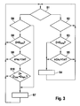
- FIG. 3 is a flowchart of a program routine cyclically executed in the controller 28 to control the turning on and off of the display device 30.
- FIG. 11 is a flowchart of a program routine cyclically executed in the controller 28 to control the turning on and off of the display device 30.
- step S1 it is checked if the display device is turned on. If this is not the case, it is checked in step S2 whether the detection module 24 has detected a target object. If this is not the case, a direct return to step S1 takes place and the display remains switched off.
- step S3 it is checked in step S3 whether the distance D of the target object is smaller than the minimum distance D min . If this is the case (as in FIG. 2 (B) ), the target display is turned on in step S4. Otherwise, in step S5, the check of the display criterion that the target acceleration a, which is determined by the dynamic parameters of the target object, is less than or equal to the sum of the target acceleration a f for free travel and a surcharge Da. If a is less than a f , this means that due to the minimum selection in the controller 26, the distance control is already effective.
- the distance control is not yet effective, but it will take effect as soon as the desired acceleration a, which decreases further when approaching the target object, drops below a f .
- step S1 If this display criterion is not met, there is a direct return to step S1. Otherwise, the display is turned on in step S4, after which a new cycle begins with step S1.
- step S6 If it is determined in step S1 that the display is on, it is checked in step S6 whether a target object is still detected. If the target object has been lost, for example in a very tight curve, the process branches to step S7 and the display is turned off. Otherwise, the display remains on, and in step S8 it is checked whether D is greater than the minimum distance D min . If this is not the case, a return to step S1 occurs and the display remains switched on. Otherwise, it is checked in step S9 whether the negative of the display criterion checked in step S5 holds. If not, the process returns to step S1 and the display remains on.
- step S5 If the display criterion defined in step S5 is no longer satisfied (result "yes” in step S9), it is additionally checked in step S10 whether the current distance D of the target object is greater than a "historical" depression D hist increased by a certain hysteresis distance D hys .
- D hist In order to determine D hist , starting with the switching on of the display in step S 4, it is checked in each measuring cycle of the locating system 10 whether the distance D measured for the target object has increased or decreased. in the In the case of a decrease, the new distance value is recorded as a current value for D hist in a register. The register is cleared as soon as the display is switched off in step S7.
- step S10 The result of the test in step S10 is that, once the display has been switched on, the display remains switched on until the distance of the target object (or of another target object which has meanwhile replaced the previous target object) is kept to a minimum decreased and then increased again at least by D hys .
- step S10 prevents the display from being first turned off and then turned on again as it approaches the target object. Only if the criterion tested in step S10 is also satisfied is the display turned off in step S7 before a new cycle begins. Otherwise, a direct return to step S1 is made from step S10.
Description
Die Erfindung betrifft eine Abstandsregelvorrichtung für Kraftfahrzeuge, mit einem Ortungssystem zur Ortung vorausfahrender Fahrzeuge, einem Erfassungsmodul zur Erfassung eines georteten Fahrzeugs als Zielobjekt für die Abstandsregelung, einem Regler zur Regelung des Abstands zum Zielobjekt, und einer Anzeigeeinrichtung mit zugehöriger Steuereinrichtung zur Anzeige eines erfaßten Zielobjekts, wobei die Steuereinrichtung dazu ausgebildet ist, den Abstand des Zielobjekts und mindestens einen weiteren vom Ortungssystem gemessenen dynamischen Parameter des Zielobjekts auszuwerten.The invention relates to a distance control device for motor vehicles, comprising a detection system for locating preceding vehicles, a detection module for detecting a located vehicle as a target for the distance control, a controller for controlling the distance to the target object, and a display device with associated control device for displaying a detected target object, wherein the control device is designed to evaluate the distance of the target object and at least one further dynamic parameter of the target object measured by the positioning system.
Solche Abstandsregelvorrichtungen, die auch als ACC-Systeme (Adaptive Cruise Control) bezeichnet werden, sind bereits in zahlreichen Kraftfahrzeugen im Einsatz. Das Ortungssystem wird üblicherweise durch einen Radarsensor mit relativ großer Ortungstiefe gebildet, der in der Lage ist, vorausfahrende Fahrzeuge bereits in einem relativ großen Abstand zu orten und deren Abstand, Relativgeschwindigkeit und Azimutwinkel zu messen. Anhand des Azimutwinkels wird für jedes geortete Fahrzeug geprüft, ob es der von dem eigenen Fahrzeug befahrenen Spur der Fahrbahn oder einer Nebenspur zuzuordnen ist. Bei gekrümmter Fahrbahn wird die Fahrbahnkrümmung berücksichtigt, die sich beispielsweise anhand der Gierrate des eigenen Fahrzeugs abschätzen läßt.Such distance control devices, which are also referred to as ACC systems (Adaptive Cruise Control), are already in use in numerous motor vehicles. The location system is usually formed by a radar sensor with a relatively large detection depth, which is able to locate vehicles ahead already at a relatively large distance and to measure their distance, relative speed and azimuth angle. Based on the azimuth angle is checked for each located vehicle, whether it is attributable to the used by the own vehicle lane of the lane or a secondary lane. When crooked Lane is the road curvature taken into account, which can be estimated, for example, based on the yaw rate of your own vehicle.
Unter den georteten Fahrzeugen identifiziert das Erfassungsmodul das auf der eigenen Fahrspur unmittelbar vorausfahrende Fahrzeug, und wenn dessen Abstand kleiner ist als ein vorgegebener Maximalabstand, der von der Fahrgeschwindigkeit des eigenen Fahrzeugs und gegebenenfalls von der Kurvigkeit der Fahrbahn abhängig ist, wird dieses Fahrzeug als Zielobjekt für die Abstandsregelung erfaßt, und seine dynamischen Daten werden als Grundlage für die Abstandsregelung an den Regler übergeben. Durch Eingriff in das Antriebssystem und gegebenenfalls das Bremssystem des Fahrzeugs wird die Geschwindigkeit des eigenen Fahrzeugs dann vom Regler so angepaßt, daß das Zielobjekt in einem angemessenen Sicherheitsabstand verfolgt wird. Dieser Sicherheitsabstand ist geschwindigkeitsabhängig und ist über die Zeitlücke zwischen den beiden Fahrzeugen identifiziert. Zumeist kann der Fahrer diese Zeitlücke innerhalb gewisser Grenzen wählen. In Freifahrt, d. h., wenn kein Zielobjekt vorhanden ist, wird die Geschwindigkeit durch den Regler auf eine vom Fahrer vorgegebene Setzgeschwindigkeit geregelt.Among the located vehicles, the detection module identifies the vehicle immediately ahead in its own lane, and if its distance is less than a predetermined maximum distance, which depends on the driving speed of the own vehicle and possibly the curvature of the road, this vehicle is the target for detects the distance control, and its dynamic data is passed as the basis for the distance control to the controller. By intervening in the drive system and, where appropriate, the braking system of the vehicle, the speed of the own vehicle is then adjusted by the controller so that the target object is tracked at an appropriate safety distance. This safety margin is speed dependent and is identified over the time gap between the two vehicles. In most cases, the driver can choose this time gap within certain limits. In free travel, ie when there is no target object, the speed is controlled by the controller to a set by the driver setting speed.
Die Anzeigeeinrichtung dient dazu, dem Fahrer die beiden Betriebszustände Freifahrt und Folgefahrt (Verfolgung eines Zielobjekts) transparent zu machen. Dies geschieht bisher in der Weise, daß auf dem Armaturenbrett des Fahrzeugs oder gegebenenfalls auch in einem Head-Up Display, das ein Anzeigebild in die Windschutzscheibe des Fahrzeugs projiziert, ein Symbol aufleuchtet, sobald das Erfassungsmodul ein Zielobjekt erfaßt und an den Regler gemeldet hat.The display device serves to make the driver aware of the two operating states free travel and following travel (tracking of a target object). This is done so far in such a way that on the dashboard of the vehicle or possibly also in a head-up display that projects a display image in the windshield of the vehicle, a symbol lights up as soon as the detection module has detected a target and reported to the controller.
Aus dem gattungsbildenden Dokument
Aufgabe der Erfindung ist es, die Anzeige des Zielobjekts für den Fahrer transparenter und plausibler zu machen.The object of the invention is to make the display of the target object for the driver more transparent and plausible.
Diese Aufgabe wird dadurch gelöst, daß der weitere dynamische Parameter oder einer der weiteren dynamischen Parameter die Relativgeschwindigkeit oder die Relativbeschleunigung des Zielobjekts ist und daß die Steuereinrichtung dazu ausgebildet ist, das Zielobjekt, nur dann anzuzeigen, wenn diese Parameter ein vorgegebenes Anzeigekriterium erfüllen, das darauf hindeutet, dass im Rahmen der Abstandregelung winkelich ein Regeleingriff stafffindet oder kurz bevorsteht.This object is achieved in that the further dynamic parameter or one of the further dynamic parameters is the relative speed or the relative acceleration of the target object and in that the control device is designed to display the target object only if these parameters fulfill a predetermined display criterion indicates that, within the scope of the distance control, a control intervention is currently at rest or imminent.
Auf diese Weise läßt sich erreichen, daß das Zielobjekt dem Fahrer nur dann angezeigt wird, wenn es auch wirklich für die Abstandsregelung relevant ist. Der Maximalabstand, den ein in der eigenen Spur vorausfahrendes Fahrzeug höchstens haben darf, damit es als Zielobjekt erfaßt wird, ist nämlich aus Sicherheitsgründen so groß gewählt, daß bei Erfassung des Zielobjekts in vielen Fällen noch nicht sofort eine Anpassung der Geschwindigkeit erforderlich ist. Vielmehr wird zunächst nur die Dynamik des Zielobjekts verfolgt, und erst wenn der Abstand unter einen von der Relativgeschwindigkeit des Zielobjekts abhängigen Wert abnimmt, wird das eigene Fahrzeug verzögert, um seine Geschwindigkeit an die des Zielobjekts anzupassen.In this way it can be achieved that the target object is displayed to the driver only if it is really relevant for the distance control. For safety reasons, the maximum distance that a vehicle traveling ahead in one's own lane may at most have, so that it is detected as the target object, is so large that, in many cases, an adaptation of the speed is not necessary when the target object is detected. Rather, initially only the dynamics of the target object are tracked, and only when the distance decreases below a dependent on the relative speed of the target object value, the own vehicle is delayed to adjust its speed to that of the target object.
Bei herkömmlichen ACC-Systemen hat dies beispielsweise in einer Situation, in der die vom Fahrer gewählte Setzgeschwindigkeit annähernd mit der Absolutgeschwindigkeit des Zielobjekts übereinstimmt, zur Folge, daß dem Fahrer das Zielobjekt bereits angezeigt wird, lange bevor durch den Regler eine Reaktion auf das Zielobjekt erfolgt. Dies wird vom Fahrer vielfach als störend oder irritierend empfunden. Besonders störend ist es, wenn das Zielobjekt mit ungleichförmger Geschwindigkeit fährt, so daß sein Abstand um den Maximalabstand für die Erfassung als Zielobjekt pendelt, mit der Folge, daß die Zielobjektanzeige abwechselnd aufleuchtet und wieder erlischt. Mit der erfindungsgemäßen Abstandsregelvorichtung läßt sich dieser Nachteil vermeiden, da die Steuereinrichtung die Zielobjektanzeige erst dann aktiviert, wenn die dynamischen Parameter des Zielobjekts so beschaffen sind, daß tatsächlich eine Abstandsregelung erfolgt oder zumindest kurz bevorsteht.In conventional ACC systems, for example, in a situation where the driver-selected set speed approximately matches the absolute speed of the target, the result is that the target is already displayed to the driver long before the controller reacts to the target , This is often perceived by the driver as annoying or irritating. It is particularly disturbing when the target object is traveling at a non-uniform speed, so that its distance fluctuates around the maximum distance for the detection as the target object, with the result that the target object display alternately lights up and goes out again. With the distance control device according to the invention, this disadvantage can be avoided since the control device activates the target object display only when the dynamic parameters of the target object are such that a distance control actually takes place or at least is imminent.
Eine andere typische Situation, in der sich die Erfindung als vorteilhaft erweist, ist eine Fahrt auf einer relativ kurvenreichen Landstraße. Aufgrund der auf Landstraßen geltenden allgemeinen Geschwindigkeitsbegrenzung (in Deutschland 100 km/h) laufen Annährungsprozesse zwischen Fahrzeugen hier zumeist sehr langsam. Das hat auf kurvigen Strecken zur Folge, daß ein bereits in großem Abstand als Zielobjekt erfaßtes Fahrzeug in der nächsten Kurve wieder aus dem Ortungsbereich des Radarsensors verschwindet und dann auf einem nachfolgenden geraden Streckenabschnitt erneut erfaßt wird. Dies kann sich mehrmals wiederholen, so daß es bei einem herkömmlichen ACC-System auch hier zu einem irritierenden Flackern der Zielobjektanzeige kommt. Durch die Erfindung wird dieser Effekt gemildert, da das Zielobjekt im allgemeinen erst in einer geringeren Entfernung angezeigt werden wird.Another typical situation in which the invention proves advantageous is a trip on a relatively winding country road. Due to the general speed limit applicable on rural roads (in Germany 100 km / h), approaching processes between vehicles are usually very slow here. This has on curved routes to the result that an already detected at a great distance as a target object vehicle disappears again in the next corner of the detection range of the radar sensor and then detected again on a subsequent straight section of track. This can be repeated several times so that it comes in a conventional ACC system here too an irritating flickering of the target display. The invention mitigates this effect, since the target object will generally only be displayed at a smaller distance.
In anderen Situationen, beispielsweise bei relativ rascher Annäherung an ein Zielobjekt, werden dagegen die dynamischen Parameter im allgemeinen so beschaffen sein, daß die Anzeige des Zielobjekts bereits kurz nach oder unmittelbar bei der Zielobjekterfassung erfolgt, so daß die Erfindung insoweit keine nachteiligen Auswirkungen hat und den Fahrer rechtzeitig über den Eintritt in den Folgefahrtmodus informiert. Da bei hoher Relativgeschwindigkeit der Abstand zum Zielobjekt rasch kleiner wird, ist in dieser Situation ein "Flackern" der Zielobjektanzeige unwahrscheinlich.In other situations, such as relatively fast approach to a target object, on the other hand, the dynamic parameters will generally be such that the display of the target object already occurs shortly after or immediately at the Zielobjekterfassung, so that the invention has no adverse effects and the Driver informed in time about entering the next drive mode. Since at high relative speed, the distance to the target object is rapidly becoming smaller, in this situation a "flickering" of the target display is unlikely.
Nur so läßt sich durch die Erfindung erreichen, daß störende oder irritierende Anzeigen vermieden werden und der Fahrer in angemessenerer Form über den wahren Zustand der Abstandsregelvorrichtung informiert wird.Only so can be achieved by the invention that annoying or irritating displays are avoided and the driver is informed in a more appropriate form about the true state of the distance control device.
Vorteilhafte Ausgestaltungen und Weiterbildungen sind in den Unteransprüchen angegeben.Advantageous embodiments and further developments are specified in the subclaims.
Die Auswertung in der Anzeigesteuerung kann sich ganz oder teilweise auf die Verarbeitungsprozesse stützen, die ohnehin im Regler ablaufen. Beispielsweise kann zu diesem Zweck die vom Regler aufgrund der dynamischen Daten des Zielobjekts berechnete Sollbeschleunigung herangezogen und mit der Sollbeschleunigung verglichen werden, die unter sonst gleichen Bedingungen für eine Freifahrtsituation gelten würde und zumeist ebenfalls fortlaufend von einem Freifahrtmodul des Reglers berechnet wird.The evaluation in the display control can be wholly or partly based on the processing processes that are running anyway in the controller. For example, the target acceleration calculated by the controller based on the dynamic data of the target object can be used for this purpose and are compared with the target acceleration, which would apply under otherwise identical conditions for a free-running situation and is usually also calculated continuously by a free travel module of the controller.
Darüber hinaus ist es zweckmäßig, den gemessenen Abstand des Zielobjekts direkt auszuwerten und das Anzeigekriterium so zu definieren, daß das Zielobjekt auf jeden Fall angezeigt wird, wenn sein Abstand kleiner ist als ein Minimalabstand, der vom Maximalabstand für die Zielobjekterfassung (und ggf. weiteren Parametern) abhängig ist. Beispielsweise kann der Mindestabstand sich von dem Maximalabstand um einen festen Betrag unterscheiden oder proportional zu diesem sein oder auch die Summe aus einem konstanten Anteil und einem proportionalen Anteil sein.In addition, it is expedient to evaluate the measured distance of the target object directly and to define the display criterion such that the target object is displayed in any case if its distance is smaller than a minimum distance, which is the maximum distance for the Zielobjekterfassung (and possibly other parameters ) is dependent. For example, the minimum distance may be different from, or proportional to, the maximum distance by a fixed amount, or may be the sum of a constant portion and a proportional portion.
In einer anderen Ausführungsform könnte der Mininimalabstand als Funktion der dynamischen Parameter, insbesondere der Relativgeschwindigkeit und gegebenenfalls der Relativbeschleunigung des Zielobjekts variiert werden, und das Anzeigekriterium könnte dann allein darin bestehen, daß der Abstand des Zielobjekts den Mininimalabstand unterschreitet.In another embodiment, the minimum distance could be varied as a function of the dynamic parameters, in particular the relative speed and, if appropriate, the relative acceleration of the target object, and the display criterion could then consist solely in that the distance of the target object falls below the minimum distance.
Um ein Flackern der Anzeige zu vermeiden, erfolgt das Ein- und Ausschalten vorzugsweise mit einer gewissen Hysterese. In einer besonders vorteilhaften Ausführungsform wird der zeitliche Verlauf des Zielobjektabstands verfolgt, und lokale Minima dieses Abstands werden gespeichert und mit dem aktuellen Abstand verglichen.In order to avoid a flickering of the display, the switching on and off is preferably carried out with a certain hysteresis. In a particularly advantageous embodiment, the time profile of the target object distance is tracked, and local minima of this distance are stored and compared with the current distance.
Wenn bei niedrigem Zielobjektabstand die Zielobjektanzeige einmal eingeschaltet wurde, wird sie erst dann wieder ausgeschaltet, wenn der Zielobjektabstand das Minimum durchlaufen hat und wieder um einen bestimmten Hysteresebetrag über dem zuletzt gespeicherten Minimum liegt. Auf diese Weise ist z. B. auch sichergestellt, daß die Anzeige eingeschaltet bleibt, wenn der Fahrer während der Annäherung an das Zielobjekt die Zeitlücke oder die Setzgeschwindigkeit verringert.If the target object display has been switched on once with a low target distance, it is not switched off again until the target distance has passed the minimum and again lies above the last stored minimum by a certain hysteresis amount. In this way, z. B. also ensures that the display remains on when the driver reduces the time gap or the set speed during the approach to the target object.
In einer modifizierten Ausführungsform kann die Steuereinrichtung für die Zielobjektanzeige mit dem Erfassungsmodul kombiniert sein und den Maximalabstand für die Erfassung eines Fahrzeugs als Zielobjekt in Abhängigkeit von anderen dynamischen Parametern variieren, beispielsweise in Abhängigkeit von der Geschwindigkeit des eigenen Fahrzeugs und der Relativgeschwindigkeit (und gegebenenfalls Beschleunigung) des Zielobjekts. Da in diesem Fall bereits die Erfassung eines Fahrzeugs als Zielobjekt von mehreren dynamischen Parametern abhängig ist, kann die Anzeige des Zielobjekts zeitgleich mit der Erfassung erfolgen, d. h., das Anzeigekriterium ist identisch mit dem Kriterium für die Zielobjekterfassung. Alternativ ist es jedoch auch in dieser Ausführungsform möglich, für die Zielobjektanzeige ein besonderes Kriterium zu definieren.In a modified embodiment, the control device for the target object display can be combined with the detection module and vary the maximum distance for the detection of a vehicle as target object as a function of other dynamic parameters, for example as a function of the speed of the own vehicle and the relative speed (and optionally acceleration). of the target object. In this case, since the detection of a vehicle as the target object is already dependent on a plurality of dynamic parameters, the display of the target object can take place at the same time as the acquisition. h., the display criterion is identical to the criterion for target object detection. Alternatively, however, it is also possible in this embodiment to define a special criterion for the target object display.
Ein Ausführungsbeispiel der Erfindung ist in den Zeichnungen dargestellt und in der nachfolgenden Beschreibung näher erläutert.An embodiment of the invention is illustrated in the drawings and explained in more detail in the following description.
- Figur 1FIG. 1
- ein Blockdiagramm einer Abstandsregelvorrichtung gemäß der Erfindung;a block diagram of a distance control device according to the invention;
- Figur 2FIG. 2
- eine Skizze zur Illustration der Funktionsweise der Vorrichtung in unterschiedlichen Verkehrssituationen; unda sketch illustrating the operation of the device in different traffic situations; and
- Figur 3FIG. 3
- ein Flußdiagramm zur Erläuterung der Arbeitsweise der Vorrichtung.a flowchart for explaining the operation of the device.
Die in
Weiterhin gehört zu der Vorrichtung eine Anzeigeeinheit 20, die dazu dient, den Fahrer über den aktuellen Betriebszustand der Abstandsregelvorrichtung zu informieren.Furthermore, the device includes a
Das Datenverarbeitungssystem 12 umfaßt mehrere Funktionsmodule, die als Softwaremodule oder auch auch spezialisierte Hardware ausgestaltet sein können.The
Ein Eingangsmodul 22 dient zur Auswertung der vom Ortungssystem 10 gelieferten Daten. Insbesondere werden hier durch Auswertung der empfangenen Radarsignale die georteten Objekte identifiziert, und die Abstände, Relativgeschwindigkeiten und Azimutwinkel dieser Objekte werden in ihrer zeitlichen Entwicklung verfolgt und an die nachgeschalteten Module weitergeleitet.An
Ein Erfassungsmodul 24 überprüft anhand dieser Daten, ob in der von dem eigenen Fahrzeug befahrenen Fahrspur mindestens ein vorausfahrendes Fahrzeug vorhanden ist, und erfaßt das unmittelbar vorausfahrende Fahrzeug, also das mit dem kleinsten Abstand, als Zielobjekt für die Abstandsregelung, sofern der Abstand dieses Fahrzeugs kleiner ist als ein vorgegebener Maximalabstand Dmax, der von der Geschwindigkeit V des eigenen Fahrzeugs und gegebenenfalls von der Kurvigkeit der Fahrbahn abhängig ist.A
Die Daten des erfaßten Zielobjekts werden dann an einen Regler 26 übergeben, der anhand dieser Daten und der Geschwindigkeit V des eigenen Fahrzeugs die eigentliche Abstands- und Geschwindigkeitsregelung vornimmt. Beispielsweise berechnet dieser Regler eine (positive oder negative) Sollbeschleunigung a, die erforderlich ist, damit das als Zielobjekt erfaßte Fahrzeug in einem vorgegebenen zeitlichen Abstand (Zeitlücke) verfolgt wird. Außerdem berechnet der Regler 26 eine Sollbeschleunigung af für den Fall, daß kein Zielobjekt erfaßt ist und die Geschwindigkeit des Fahrzeugs auf eine vom Fahrer gewählte Setzgeschwindigkeit zu regeln ist. Anhand einer Minimumauswahl zwischen diesen beiden Sollbeschleunigungen bestimmt der Regler dann die Ausgangssignale für die Ansteuerung der Aktoren 14, 16.The data of the detected target object are then transferred to a
Als weiteres Funktionsmodul enthält das Datenverarbeitungssystem 12 eine Steuereinrichtung 28 und zur Ansteuerung der Anzeigeeinheit 20. Im gezeigten Beispiel umfaßt die Anzeigeeinheit 20 eine Anzeigeeinrichtung 30 in der Form einer Leuchtanzeige, die ein stilisiertes Fahrzeugheck darstellt und als Zielobjektanzeige dient, sowie eine Leuchtanzeige 32 in der Form eines stilisierten Fahrbahnabschnitts mit horizontalen Abstandsbalken, deren Anzahl über die derzeit vom Fahrer gewählte Zeitlücke Auskunft gibt.As another function module, the
Die als Zielobjektanzeige dienende Anzeigeeinrichtung 30 leuchtet nur unter der Bedingung auf, daß das Erfassungsmodul 24 ein Zielobjekt erfaßt hat. Bei der hier vorgeschlagenen Vorrichtung soll die Zielobjektanzeige den Fahrer jedoch speziell darüber informieren, daß das Zielobjekt nicht nur erfaßt wurde, sondern daß auch der Regler 26 im Begriff ist, auf dieses Zielobjekt zu reagieren. Zu diesem Zweck wertet die Steuereinrichtung 28 zum einen den vom Erfassungsmodul 24 gemeldeten Abstand D des Zielobjekts und zum anderen die vom Regler 26 berechneten Sollbeschleunigungen a und af aus. Diese Sollbeschleunigungen enthalten implizit Information über die dynamischen Parameter des Zielobjekts, insbesondere seine Relativgeschwindigkeit und gegebenenfalls Relativbeschleunigung.The
In
Der Abstand D liegt hier in einem Intervall zwischen Dmax und einem Minimalabstand Dmin, der von Dmax abhängig ist und beispielsweise um einen festen Betrag kleiner ist als Dmax. Unter diesen Umständen wird die Anzeigeeinrichtung 30 (Zielobjektanzeige) durch die Steuereinrichtung 28 nur dann aktiviert, wenn zusätzlich die Sollbeschleunigungen a und af ein bestimmtes Kriterium erfüllen, das darauf hindeutet, daß eine Reaktion des Reglers 26 auf das Zielobjekt 36 unmittelbar bevorsteht oder bereits eingetreten ist.The distance D is here in an interval between D max and a minimum distance D min , which depends on D max and, for example, by a fixed amount is smaller than D max . Under these circumstances, the display device 30 (target object display) is only activated by the
Wenn dagegen die vom Fahrer gewählte Setzgeschwindigkeit kleiner ist als die Fahrgeschwindigkeit des Zielobjekts 36, braucht der Regler 26 nicht auf das Zielobjekt zu reagieren, und die Ansteuerung der Aktoren 14, 16 beruht auf der für eine Freifahrtsituation berechneten Sollbeschleunigung af. Das gleiche gilt, wenn die Geschwindigkeit V des eigenen Fahrzeugs nur wenig größer ist als die Fahrgeschwindigkeit des Zielobjekts 36 und gleichzeitig der Abstand D noch relativ groß ist.If, on the other hand, the setting speed selected by the driver is smaller than the traveling speed of the
In diesem Fällen bleibt die Zielobjektanzeige ausgeschaltet, weshalb die Anzeigeeinrichtung 30 in
In
Der Minimalabstand Dmin ist so klein gewählt, daß im Regelfall in absehbarer Zeit eine Reaktion des Reglers 26 auf das Zielobjekt erfolgen wird und daß außerdem das Zielobjekt 36 normalerweise stabil im Ortungsbereich des Radarsensors bleiben wird. So wird in den meisten Fällen das für den Fahrer irritierende Phänomen vermieden, daß die Anzeigeeinrichtung 30 kurz aufleuchtet und dann wieder erlischt, ohne daß irgendeine Reaktion des Abstandsregelsystems spürbar geworden ist.The minimum distance D min is chosen so small that as a rule in the foreseeable future, a reaction of the
Wenn der im Erfassungsmodul 24 definierte Maximalabstand Dmax von der Kurvigkeit der Fahrbahn abhängig ist und der Minimalabstand Dmin wiederum eine monoton steigende Funktion von Dmax ist, so ist auch Dmin von der Kurvigkeit der Fahrbahn abhängig und wird umso kleiner, je größer die Wahrscheinlichkeit ist, daß das Zielobjekt 36 aus dem Ortungsbereich des Radarsensors verloren geht.If the maximum distance D max defined in the
In Schritt S1 wird geprüft, ob die Anzeigeeinrichtung eingeschaltet ist. Wenn dies nicht der Fall ist, wird in Schritt S2 geprüft, ob das Erfassungsmodul 24 ein Zielobjekt erfaßt hat. Ist dies nicht der Fall, erfolgt ein direkter Rücksprung zu Schritt S1, und die Anzeige bleibt ausgeschaltet.In step S1, it is checked if the display device is turned on. If this is not the case, it is checked in step S2 whether the
Wenn dagegen ein Zielobjekt erfaßt ist, wird in Schritt S3 geprüft, ob der Abstand D des Zielobjekts kleiner ist als der Minimalabstand Dmin. Wenn dies der Fall ist (wie in
Ist dieses Anzeigekriterium nicht erfüllt, erfolgt ein direkter Rücksprung zu Schritt S1. Andernfalls wird in Schritt S4 die Anzeige eingeschaltet, wonach mit Schritt S1 ein neuer Zyklus beginnt.If this display criterion is not met, there is a direct return to step S1. Otherwise, the display is turned on in step S4, after which a new cycle begins with step S1.
Wenn in Schritt S1 festgestellt wird, daß die Anzeige eingeschaltet ist, wird in Schritt S6 geprüft, ob nach wie vor ein Zielobjekt erfaßt ist. Wenn das Zielobjekt verloren wurde, beispielsweise in einer sehr engen Kurve, wird zu Schritt S7 verzweigt, und die Anzeige wird ausgeschaltet. Andernfalls bleibt die Anzeige eingeschaltet, und in Schritt S8 wird geprüft, ob D größer ist als der Minimalabstand Dmin. Ist dies nicht der Fall, erfolgt ein Rücksprung zu Schritt S1 und die Anzeige bleibt eingeschaltet. Andernfalls wird in Schritt S9 geprüft, ob die Verneinung des in Schritt S5 geprüften Anzeigekriteriums gilt. Wenn nein, wird wieder zu Schritt S1 verzweigt, und die Anzeige bleibt eingeschaltet.If it is determined in step S1 that the display is on, it is checked in step S6 whether a target object is still detected. If the target object has been lost, for example in a very tight curve, the process branches to step S7 and the display is turned off. Otherwise, the display remains on, and in step S8 it is checked whether D is greater than the minimum distance D min . If this is not the case, a return to step S1 occurs and the display remains switched on. Otherwise, it is checked in step S9 whether the negative of the display criterion checked in step S5 holds. If not, the process returns to step S1 and the display remains on.
Ist das in Schritt S5 definierte Anzeigekriterium nicht mehr erfüllt (Ergebnis "Ja" in Schritt S9), so wird in Schritt S10 zusätzlich geprüft, ob der aktuelle Abstand D des Zielobjekts größer ist als ein "historischer" Tiefstand Dhist vermehrt um einen gewissen Hystereseabstand Dhys. Zur Bestimmung von Dhist wird, beginnend mit dem Einschalten der Anzeige in Schritt S4, in jedem Meßzyklus des Ortungssystems 10 geprüft, ob der für das Zielobjekt gemessene Abstand D zu- oder abgenommen hat. Im Fall einer Abnahme wird der neue Abstandswert als aktueller Wert für Dhist in einem Register festgehalten. Das Register wird gelöscht, sobald in Schritt S7 die Anzeige ausgeschaltet wird. Die Prüfung im Schritt S10 hat zur Folge, daß die Anzeige, wenn sie einmal eingeschaltet wurde, so lange eigeschaltet bleibt, bis der Abstand des Zielobjekts (oder auch eines anderen Zielobjekts, das inzwischen an die Stelle des bisherigen Zielobjekts getreten ist) auf ein Minimum abgenommen und dann wieder mindestens um Dhys zugenommen hat.If the display criterion defined in step S5 is no longer satisfied (result "yes" in step S9), it is additionally checked in step S10 whether the current distance D of the target object is greater than a "historical" depression D hist increased by a certain hysteresis distance D hys . In order to determine D hist , starting with the switching on of the display in
Wenn der Fahrer nach dem Einschalten der Zielobjektanzeige z. B. die Zeitlücke verkleinert oder die Setzgeschwindigkeit verringert, so hat dies eine Zunahme der Sollbeschleunigung a bzw. eine Abnahme der Sollbeschleunigung af zur Folge, so daß die Abfrage in Schritt S9 positiv ausfiele. In diesen Fällen verhindert Schritt S10, daß die Anzeige zunächst ausgeschaltet und dann bei weiterer Annäherung an das Zielobjekt wieder eingeschaltet wird. Nur wenn auch das in Schritt S10 geprüfte Kriterium erfüllt ist, wird in Schritt S7 die Anzeige ausgeschaltet, bevor ein neuer Zyklus beginnt. Andernfalls erfolgt von Schritt S10 ein direkter Rücksprung zu Schritt S1.If the driver after switching on the target object display z. B. decreases the time gap or reduces the set speed, this has an increase of the target acceleration a or a decrease in the desired acceleration a f result, so that the query in step S9 positive failed. In these cases, step S10 prevents the display from being first turned off and then turned on again as it approaches the target object. Only if the criterion tested in step S10 is also satisfied is the display turned off in step S7 before a new cycle begins. Otherwise, a direct return to step S1 is made from step S10.
Claims (7)
- Device for distance control for motor vehicles,- having a location-determining system (10) for determining the location of vehicles travelling ahead,- a detection module (24) for detecting a located vehicle as a target object (36) for the distance control,- a controller (26) for controlling the distance from the target object, and- a display device (30) with an associated control device (28) for displaying a detected target object,- wherein the control device (28) is designed to evaluate the distance (D) of the target object (36) and at least one further dynamic parameter of the target object measured by the location-determining system (10),characterized in that- the further dynamic parameter or one of the further dynamic parameters is the relative speed or the relative acceleration of the target object (36), and- in that the control device (28) is designed to display the target object only when these parameters meet a predefined display criterion which indicates that in fact a control intervention is taking place or is directly immanent within the scope of the distance control.
- Device for distance control according to one of the preceding claims, characterized in that the control device (28) is designed to evaluate at least one set point acceleration (a, af) which is calculated by the controller (26) and is itself dependent on the dynamic parameters of the target object (36).
- Device for distance control according to one of the preceding claims, characterized in that the control device (28) is designed to switch on the display device (30) in all cases if the distance (D) of the target object (36) is shorter than a minimum distance (Dmin).
- Device for distance control according to Claim 3, characterized in that the minimum distance (Dmin) is a function of a maximum distance (Dmax) at which a vehicle can be situated at maximum for it to be detected as a target object by the detection module (24).
- Device for distance control according to one of the preceding claims, characterized in that the display criterion consists in the fact that a set point acceleration (a) which is necessary within the scope of the distance control is smaller than an acceleration (af + Da) which is dependent on a set point acceleration (af) which is calculated for an unrestricted travel situation without a detected target object.
- Device for distance control according to one of the preceding claims, characterized in that the control device (28) has a hysteresis function for switching the display device (30) on and off.
- Device for distance control according to Claim 6, characterized in that the control device (28) is designed, at least when the display device (30) is switched on, to track the distance (D) of the target object (36) and to store the respective shortest distance (Dhist) and to keep the display device (30) switched on if the current distance (D) of the target object is not longer than the stored shortest distance (Dhist) by at least one specific hysteresis distance (Dhys).
Applications Claiming Priority (1)
| Application Number | Priority Date | Filing Date | Title |
|---|---|---|---|
| DE102006043091A DE102006043091A1 (en) | 2006-09-14 | 2006-09-14 | Distance control device with target object display |
Publications (3)
| Publication Number | Publication Date |
|---|---|
| EP1900586A2 EP1900586A2 (en) | 2008-03-19 |
| EP1900586A3 EP1900586A3 (en) | 2009-10-14 |
| EP1900586B1 true EP1900586B1 (en) | 2013-06-26 |
Family
ID=38826415
Family Applications (1)
| Application Number | Title | Priority Date | Filing Date |
|---|---|---|---|
| EP07113708.7A Active EP1900586B1 (en) | 2006-09-14 | 2007-08-02 | Device for distance control with target object display |
Country Status (2)
| Country | Link |
|---|---|
| EP (1) | EP1900586B1 (en) |
| DE (1) | DE102006043091A1 (en) |
Families Citing this family (7)
| Publication number | Priority date | Publication date | Assignee | Title |
|---|---|---|---|---|
| DE102010021591B4 (en) * | 2010-05-26 | 2024-02-01 | Audi Ag | Method for controlling the operation of a fully automatic driver assistance system of a motor vehicle and motor vehicle designed for independent vehicle control |
| DE102012214873A1 (en) | 2012-08-22 | 2014-03-20 | Robert Bosch Gmbh | Method and device for signaling a driving instruction for a driver of a vehicle |
| CN105346389A (en) * | 2014-08-18 | 2016-02-24 | 比亚迪股份有限公司 | Control system and method for vehicle, and vehicle |
| CN108284833B (en) * | 2017-09-12 | 2019-10-25 | 腾讯科技(深圳)有限公司 | The method and apparatus that Driving control is carried out to vehicle |
| JP6898658B2 (en) * | 2018-06-13 | 2021-07-07 | 株式会社Subaru | Vehicle driving support device |
| DE102018219283A1 (en) * | 2018-11-12 | 2020-05-14 | Zf Friedrichshafen Ag | Speed determination for a motor vehicle |
| JP2022127994A (en) * | 2021-02-22 | 2022-09-01 | スズキ株式会社 | vehicle control system |
Family Cites Families (5)
| Publication number | Priority date | Publication date | Assignee | Title |
|---|---|---|---|---|
| JP2987778B2 (en) * | 1990-11-30 | 1999-12-06 | アイシン精機株式会社 | Vehicle speed control device |
| DE19958520A1 (en) * | 1999-12-04 | 2001-06-07 | Bosch Gmbh Robert | Speed controller for a motor vehicle |
| JP4066609B2 (en) * | 2001-03-19 | 2008-03-26 | 日産自動車株式会社 | Status display device for vehicle travel control device |
| DE10323465A1 (en) * | 2003-05-23 | 2004-12-30 | Robert Bosch Gmbh | Vehicle speed control device |
| WO2005037592A1 (en) * | 2003-09-23 | 2005-04-28 | Daimlerchrysler Ag | Method and device for recognising lane changing operations for a motor vehicle |
-
2006
- 2006-09-14 DE DE102006043091A patent/DE102006043091A1/en not_active Withdrawn
-
2007
- 2007-08-02 EP EP07113708.7A patent/EP1900586B1/en active Active
Also Published As
| Publication number | Publication date |
|---|---|
| EP1900586A3 (en) | 2009-10-14 |
| EP1900586A2 (en) | 2008-03-19 |
| DE102006043091A1 (en) | 2008-03-27 |
Similar Documents
| Publication | Publication Date | Title |
|---|---|---|
| DE19637245C2 (en) | Method and device for regulating the speed of a vehicle | |
| EP1940665B1 (en) | Adaptive cruise control featuring recognition of a traffic jam | |
| EP1890903B1 (en) | Adaptive speed controller with situation-dependent dynamic matching | |
| EP2130194B1 (en) | Collision warning device for motor vehicles | |
| EP1381530B1 (en) | Method and device for assisting an overtaking maneuver in motor vehicles | |
| EP1777143B1 (en) | Lane-change assistant | |
| EP3281831A1 (en) | Control system and control method for determining a likelihood of a lane change by a preceding vehicle | |
| EP1900586B1 (en) | Device for distance control with target object display | |
| WO2006122867A1 (en) | Lane change assistant for motor vehicles | |
| EP2060466B1 (en) | Driver assistance system for motor vehicles | |
| DE102005045018A1 (en) | Device for longitudinal guidance of a motor vehicle | |
| EP1577682A1 (en) | Object locating system for vehicles to recognize lane change | |
| DE102010020047A1 (en) | Method for adaptation of reference distance preset for distance control system of vehicle to momentary traffic situation, involves controlling potential movement of third party vehicles during non-existence of preset emergency situation | |
| DE102007029483A1 (en) | Distance control system for motor vehicles, has positioning system for positioning of vehicles driving ahead and reaction module, which is provided to release stepped reaction of controller depending on merging | |
| DE102013214308A1 (en) | Distance controller for motor vehicles | |
| WO2009109419A1 (en) | Longitudinal guide assistant with lateral assistance function for motor vehicles | |
| DE102017209533A1 (en) | Lane change assistance system and lane change assistance method with increased safety for the driver and other road users | |
| DE102017011140A1 (en) | Control system and control method for driving a motor vehicle and avoiding a collision with another motor vehicle | |
| DE102016224061A1 (en) | Lane change assistance system with relatively speed-dependent reaction area | |
| WO2014206655A1 (en) | Prediction of a future driving path of a vehicle | |
| DE102014210174A1 (en) | Determining a critical vehicle condition and a minimum vehicle distance | |
| DE102008001105A1 (en) | Steering torque automatically influencing method for motor vehicle steering system, involves providing counter steering torque with minimum value in target track's region and progressively stepping up torque with increased distance to track | |
| EP1538018B1 (en) | Method and device for setting the return force of a accelerator pedal | |
| WO2021104804A1 (en) | Method and system for recognising an object which is turning off | |
| EP2527221B1 (en) | Method for operating a longitudinally guiding driver assistance system of a motor vehicle and motor vehicle |
Legal Events
| Date | Code | Title | Description |
|---|---|---|---|
| PUAI | Public reference made under article 153(3) epc to a published international application that has entered the european phase |
Free format text: ORIGINAL CODE: 0009012 |
|
| AK | Designated contracting states |
Kind code of ref document: A2 Designated state(s): AT BE BG CH CY CZ DE DK EE ES FI FR GB GR HU IE IS IT LI LT LU LV MC MT NL PL PT RO SE SI SK TR |
|
| AX | Request for extension of the european patent |
Extension state: AL BA HR MK YU |
|
| PUAL | Search report despatched |
Free format text: ORIGINAL CODE: 0009013 |
|
| AK | Designated contracting states |
Kind code of ref document: A3 Designated state(s): AT BE BG CH CY CZ DE DK EE ES FI FR GB GR HU IE IS IT LI LT LU LV MC MT NL PL PT RO SE SI SK TR |
|
| AX | Request for extension of the european patent |
Extension state: AL BA HR MK RS |
|
| RIC1 | Information provided on ipc code assigned before grant |
Ipc: B60K 37/00 20060101ALI20090907BHEP Ipc: B60K 35/00 20060101ALI20090907BHEP Ipc: B60W 30/16 20060101ALI20090907BHEP Ipc: B60W 30/14 20060101ALI20090907BHEP Ipc: B60W 10/18 20060101ALI20090907BHEP Ipc: B60W 10/06 20060101AFI20080102BHEP |
|
| 17P | Request for examination filed |
Effective date: 20100414 |
|
| 17Q | First examination report despatched |
Effective date: 20100520 |
|
| AKX | Designation fees paid |
Designated state(s): DE FR GB IT SE |
|
| GRAP | Despatch of communication of intention to grant a patent |
Free format text: ORIGINAL CODE: EPIDOSNIGR1 |
|
| INTG | Intention to grant announced |
Effective date: 20130405 |
|
| GRAS | Grant fee paid |
Free format text: ORIGINAL CODE: EPIDOSNIGR3 |
|
| GRAA | (expected) grant |
Free format text: ORIGINAL CODE: 0009210 |
|
| AK | Designated contracting states |
Kind code of ref document: B1 Designated state(s): DE FR GB IT SE |
|
| REG | Reference to a national code |
Ref country code: GB Ref legal event code: FG4D Free format text: NOT ENGLISH |
|
| REG | Reference to a national code |
Ref country code: DE Ref legal event code: R096 Ref document number: 502007011946 Country of ref document: DE Effective date: 20130822 |
|
| PG25 | Lapsed in a contracting state [announced via postgrant information from national office to epo] |
Ref country code: SE Free format text: LAPSE BECAUSE OF FAILURE TO SUBMIT A TRANSLATION OF THE DESCRIPTION OR TO PAY THE FEE WITHIN THE PRESCRIBED TIME-LIMIT Effective date: 20130626 |
|
| PLBE | No opposition filed within time limit |
Free format text: ORIGINAL CODE: 0009261 |
|
| STAA | Information on the status of an ep patent application or granted ep patent |
Free format text: STATUS: NO OPPOSITION FILED WITHIN TIME LIMIT |
|
| GBPC | Gb: european patent ceased through non-payment of renewal fee |
Effective date: 20130926 |
|
| PG25 | Lapsed in a contracting state [announced via postgrant information from national office to epo] |
Ref country code: IT Free format text: LAPSE BECAUSE OF FAILURE TO SUBMIT A TRANSLATION OF THE DESCRIPTION OR TO PAY THE FEE WITHIN THE PRESCRIBED TIME-LIMIT Effective date: 20130626 |
|
| 26N | No opposition filed |
Effective date: 20140327 |
|
| REG | Reference to a national code |
Ref country code: DE Ref legal event code: R097 Ref document number: 502007011946 Country of ref document: DE Effective date: 20140327 |
|
| PG25 | Lapsed in a contracting state [announced via postgrant information from national office to epo] |
Ref country code: GB Free format text: LAPSE BECAUSE OF NON-PAYMENT OF DUE FEES Effective date: 20130926 |
|
| REG | Reference to a national code |
Ref country code: FR Ref legal event code: PLFP Year of fee payment: 10 |
|
| REG | Reference to a national code |
Ref country code: FR Ref legal event code: PLFP Year of fee payment: 11 |
|
| REG | Reference to a national code |
Ref country code: FR Ref legal event code: PLFP Year of fee payment: 12 |
|
| PGFP | Annual fee paid to national office [announced via postgrant information from national office to epo] |
Ref country code: FR Payment date: 20200820 Year of fee payment: 14 |
|
| PG25 | Lapsed in a contracting state [announced via postgrant information from national office to epo] |
Ref country code: FR Free format text: LAPSE BECAUSE OF NON-PAYMENT OF DUE FEES Effective date: 20210831 |
|
| PGFP | Annual fee paid to national office [announced via postgrant information from national office to epo] |
Ref country code: DE Payment date: 20231025 Year of fee payment: 17 |