EP1900557A2 - Operating method for refrigerant safety system - Google Patents
Operating method for refrigerant safety system Download PDFInfo
- Publication number
- EP1900557A2 EP1900557A2 EP07075749A EP07075749A EP1900557A2 EP 1900557 A2 EP1900557 A2 EP 1900557A2 EP 07075749 A EP07075749 A EP 07075749A EP 07075749 A EP07075749 A EP 07075749A EP 1900557 A2 EP1900557 A2 EP 1900557A2
- Authority
- EP
- European Patent Office
- Prior art keywords
- air conditioning
- conditioning system
- response
- ventilating
- sensing
- Prior art date
- Legal status (The legal status is an assumption and is not a legal conclusion. Google has not performed a legal analysis and makes no representation as to the accuracy of the status listed.)
- Withdrawn
Links
Images

Classifications
-
- B—PERFORMING OPERATIONS; TRANSPORTING
- B60—VEHICLES IN GENERAL
- B60H—ARRANGEMENTS OF HEATING, COOLING, VENTILATING OR OTHER AIR-TREATING DEVICES SPECIALLY ADAPTED FOR PASSENGER OR GOODS SPACES OF VEHICLES
- B60H1/00—Heating, cooling or ventilating devices
- B60H1/00642—Control systems or circuits; Control members or indication devices for heating, cooling or ventilating devices
- B60H1/00978—Control systems or circuits characterised by failure of detection or safety means; Diagnostic methods
-
- B—PERFORMING OPERATIONS; TRANSPORTING
- B60—VEHICLES IN GENERAL
- B60H—ARRANGEMENTS OF HEATING, COOLING, VENTILATING OR OTHER AIR-TREATING DEVICES SPECIALLY ADAPTED FOR PASSENGER OR GOODS SPACES OF VEHICLES
- B60H1/00—Heating, cooling or ventilating devices
- B60H1/00421—Driving arrangements for parts of a vehicle air-conditioning
- B60H1/00428—Driving arrangements for parts of a vehicle air-conditioning electric
-
- F—MECHANICAL ENGINEERING; LIGHTING; HEATING; WEAPONS; BLASTING
- F25—REFRIGERATION OR COOLING; COMBINED HEATING AND REFRIGERATION SYSTEMS; HEAT PUMP SYSTEMS; MANUFACTURE OR STORAGE OF ICE; LIQUEFACTION SOLIDIFICATION OF GASES
- F25B—REFRIGERATION MACHINES, PLANTS OR SYSTEMS; COMBINED HEATING AND REFRIGERATION SYSTEMS; HEAT PUMP SYSTEMS
- F25B49/00—Arrangement or mounting of control or safety devices
- F25B49/005—Arrangement or mounting of control or safety devices of safety devices
-
- F—MECHANICAL ENGINEERING; LIGHTING; HEATING; WEAPONS; BLASTING
- F25—REFRIGERATION OR COOLING; COMBINED HEATING AND REFRIGERATION SYSTEMS; HEAT PUMP SYSTEMS; MANUFACTURE OR STORAGE OF ICE; LIQUEFACTION SOLIDIFICATION OF GASES
- F25B—REFRIGERATION MACHINES, PLANTS OR SYSTEMS; COMBINED HEATING AND REFRIGERATION SYSTEMS; HEAT PUMP SYSTEMS
- F25B2345/00—Details for charging or discharging refrigerants; Service stations therefor
- F25B2345/002—Collecting refrigerant from a cycle
-
- F—MECHANICAL ENGINEERING; LIGHTING; HEATING; WEAPONS; BLASTING
- F25—REFRIGERATION OR COOLING; COMBINED HEATING AND REFRIGERATION SYSTEMS; HEAT PUMP SYSTEMS; MANUFACTURE OR STORAGE OF ICE; LIQUEFACTION SOLIDIFICATION OF GASES
- F25B—REFRIGERATION MACHINES, PLANTS OR SYSTEMS; COMBINED HEATING AND REFRIGERATION SYSTEMS; HEAT PUMP SYSTEMS
- F25B2500/00—Problems to be solved
- F25B2500/22—Preventing, detecting or repairing leaks of refrigeration fluids
- F25B2500/222—Detecting refrigerant leaks
-
- F—MECHANICAL ENGINEERING; LIGHTING; HEATING; WEAPONS; BLASTING
- F25—REFRIGERATION OR COOLING; COMBINED HEATING AND REFRIGERATION SYSTEMS; HEAT PUMP SYSTEMS; MANUFACTURE OR STORAGE OF ICE; LIQUEFACTION SOLIDIFICATION OF GASES
- F25B—REFRIGERATION MACHINES, PLANTS OR SYSTEMS; COMBINED HEATING AND REFRIGERATION SYSTEMS; HEAT PUMP SYSTEMS
- F25B45/00—Arrangements for charging or discharging refrigerant
-
- Y—GENERAL TAGGING OF NEW TECHNOLOGICAL DEVELOPMENTS; GENERAL TAGGING OF CROSS-SECTIONAL TECHNOLOGIES SPANNING OVER SEVERAL SECTIONS OF THE IPC; TECHNICAL SUBJECTS COVERED BY FORMER USPC CROSS-REFERENCE ART COLLECTIONS [XRACs] AND DIGESTS
- Y02—TECHNOLOGIES OR APPLICATIONS FOR MITIGATION OR ADAPTATION AGAINST CLIMATE CHANGE
- Y02T—CLIMATE CHANGE MITIGATION TECHNOLOGIES RELATED TO TRANSPORTATION
- Y02T10/00—Road transport of goods or passengers
- Y02T10/80—Technologies aiming to reduce greenhouse gasses emissions common to all road transportation technologies
- Y02T10/88—Optimized components or subsystems, e.g. lighting, actively controlled glasses
Definitions
- the subject invention relates to an air conditioning system, and more specifically, to a method of operating a directed relief valve to ventilate a refrigerant from the air conditioning system.
- Air conditioning systems with directed relief valves for ventilating refrigerant are well known in the art.
- An example of such a system is disclosed in the U.S. Pat. No. 6,085,531 (the '531 patent) to Numoto et al.
- the '531 patent discloses an air conditioning system utilizing a flammable refrigerant, such as propane.
- the system includes the standard components of a compressor, a condenser, an expansion device, and an evaporator.
- the system also includes a sensor to continuously monitor leakage of the refrigerant, particularly in an air space. When a leak is detected, the sensor generates a signal.
- a directed relief valve receives the signal and opens the valve in response to the signal to ventilate the refrigerant to the surrounding atmosphere.
- the U.S. Pat. No. 6,912,860 (the '860 patent) to Zima et al. discloses another air conditioning system utilizing a potentially toxic or flammable refrigerant and includes the same standard components and a sensor to continuously monitor leakage of the refrigerant.
- the '860 patent additionally discloses a method for checking proper sensor operation. When a single sensor is utilized and a malfunction is determined, a controller generates a malfunction signal to be sent to the operator, and the system ventilates the refrigerant to the surrounding atmosphere. In the event that less than all of the plurality of sensors show a malfunction when a plurality of sensors are utilized, a controller generates a malfunction signal to be sent to the operator without ventilating the refrigerant. However, in the event that all of the plurality of sensors indicate a malfunction, the controller generates a malfunction signal and actually ventilates the refrigerant to the surrounding atmosphere.
- the invention provides a method of ventilating an air conditioning system having a controller and a sensor for sensing the presence of the refrigerant outside of the air conditioning system in a vehicle.
- the method comprises the steps of sensing a first concentration of the refrigerant outside of the air conditioning system with the sensor and periodically performing the sensing step with the controller at the expiration of every predetermined period of time without performing the sensing step during the predetermined period.
- the method will monitor for unacceptable concentration of refrigerant from any potential leaks into the passenger compartment and if detected, discharge the refrigerant from the refrigerant loop via directed relief valves.
- the method will protect the vehicle occupants with the vehicle power whether the engine is operative or inoperative by periodically sensing for an unacceptable refrigerant concentration. With today's sensor and battery technology, sensing for an unacceptable refrigerant concentration can be cycled when the engine is inoperative to avoid draining either the vehicle battery or the directed relief system back-up battery.
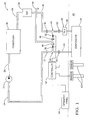
- Figure 1 is a schematic view of a first embodiment of an air conditioning system showing a thermostatic expansion valve implemented as an expansion device;
- Figure 2 is a schematic view of a second embodiment of the air conditioning system showing an orifice tube implemented as the expansion device;
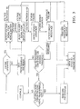
- Figure 3 is a flowchart showing an algorithm for operating a directed relief system for use with the air conditioning system.
- FIG 3 a method of ventilating an air conditioning system 20 is shown in Figure 3.
- An example of such an air conditioning system is shown at 20 in Figure 1.
- the method may be used to ventilate alternative air conditioning systems 20.
- the air conditioning system 20 is located in a vehicle having an engine and a vehicle battery.
- the air conditioning system 20 is implemented into a building, an industrial cooling system, a refrigerator, etc.
- the air conditioning system 20 utilizes a refrigerant.
- the refrigerant is of type R-152a or carbon dioxide (CO 2 ).
- CO 2 carbon dioxide
- refrigerants include, but are not limited to R-12/CFC-12, R-134a/HFC-134a, isobutane, and propane.
- a compressor 22 is operatively connected to a suction line 24.
- the suction line 24 contains the refrigerant in a low pressure, gaseous state.
- the compressor 22 receives the refrigerant from the suction line 24 and compresses the refrigerant into a high-pressure gaseous state.
- a gas line 26 is operatively connected to the compressor 22 for receiving the refrigerant and transporting it along in the system.
- a condenser 28 or gas cooler is operatively connected to the gas line 26.
- the condenser 28 cools the refrigerant received from the gas line 26.
- the condenser 28 dissipates heat removed from the refrigerant to the environment.
- a liquid line 30 is operatively connected to the condenser 28 for receiving the refrigerant from the condenser 28.
- An expansion device 32 is operatively connected to the liquid line 30.
- An evaporator 34 is also operatively connected to the expansion device 32.
- the expansion device 32 restricts the flow of the refrigerant using the Joules-Thompson effect to significantly cool and lower the pressure of the refrigerant before entering the evaporator 34.
- a thermostatic expansion valve (TXV) 36 performs the function of the expansion device 32.
- the TXV 36 dynamically regulates the flow of refrigerant into the evaporator 34.
- a receiver/dryer 38 is typically connected in-line with the liquid line 30.
- an orifice tube 40 is used as a static, fixed implementation of the expansion device 32.
- An accumulator/dehydrator 42 is implemented in-line with the suction line 24 in the second embodiment.
- the evaporator 34 is preferably located within an air space 44 and includes a series of coils. As air flows through the air space 44 and the evaporator 34, it is cooled by heat exchange with the coils of the evaporator 34.
- the evaporator 34 is also operatively connected to the suction line 24 for sending the now low-pressure, mostly gaseous refrigerant back to the compressor 22.
- a first directed relief valve 46 is integrated with the air conditioning system 20 in order to ventilate the refrigerant to the atmosphere.
- the first directed relief valve 46 includes an ambient port 48 open to the atmosphere.
- the first directed relief valve 46 also includes an inlet 50 for receiving the refrigerant and an outlet 52 for sending the refrigerant.
- the inlet 50 and outlet 52 are operatively connected inline to one of the lines 24, 26, 30, such as the suction line 24, the gas line 26, or the liquid line 30.
- Additional directed relief valves, such as a second directed relief valve 54 may also be implemented in the system.
- the embodiments shown in Figures 1 and 2 illustrate the first directed relief valve 46 in-line with the liquid line 30 and the second directed relief valve 54 in-line with the suction line 24.
- Those skilled in the art realize that alternate locations and quantities of the directed relief valves 46 are possible. However, for ease of illustration, only the first directed relief valve 46 will be described hereforth.
- a squib 56 is positioned within the first directed relief valve 46 to block the inlet 50 and the outlet 52 from the ambient port 48.
- refrigerant enters the inlet 50 and flows out the outlet 52; no refrigerant flows to the ambient port 48.
- the squib 56 detonates and deflagrates, thus unblocking the inlet 50 and the outlet 52 from the ambient port 48. Refrigerant then flows in through the inlet 50 and the outlet 52 to the ambient port 48.
- the ambient port 48 is preferably connected to a port tube 58.
- the port tube 58 leads to a location away from the air space 44 for ventilating the refrigerant to the atmosphere.
- ventilating the refrigerant from the system takes about six to ten seconds. Ventilation of the refrigerant may be required for a number of reasons, including, but not limited to, potential toxicity or flammability related to the refrigerant.
- the air conditioning system 20 uses a sensor 60 for detecting refrigerant should a leak occur.
- the sensor 60 is preferably located in the air space 44, close to the evaporator 34.
- the sensor 60 senses the refrigerant and produces a sensor 60 signal in response to sensing the refrigerant.
- additional sensors 60 may be required.
- Various types of acceptable sensors 60 are well known to those skilled in the art. These types include, but are not limited to, sensors 60 utilizing infrared light, LED's, or a heating element.
- a controller 62 is electrically connected to the sensor 60 and the squib 56.
- the controller 62 contains all the necessary electrical and electronic components to perform its function as described herein. These components include, but are not limited to, a power supply, a microprocessor, an analog-to-digital converter, an amplifier, and a relay.
- the controller 62 receives a sensor 60 signal from the sensor 60.
- the controller 62 analyzes the sensor 60 signal by comparing a current value of the signal to a lookup table, equations, or other set of predetermined values stored within the controller 62. From analyzing the sensor 60 signal, the controller 62 determines whether no refrigerant leak is detected, a refrigerant leak is detected, or the sensor 60 has malfunctioned.
- the controller 62 In response to the sensor 60 signal indicating that a refrigerant leak is detected, the controller 62 sends a ventilation signal to the squib 56. The squib 56 then initiates an opening by deflagrating, causing the refrigerant to be discharged from the system to the atmosphere.
- An operator panel 64 is also electrically connected to the controller 62.
- the operator panel 64 can be an instrument panel, an electronic display, a speaker, or other similar mechanism to convey messages to an operator of the vehicle.
- the controller 62 sends a directed relief system (DRS) ventilation message to the operator panel 64 in response to the squib 56 being deflagrated.
- DRS ventilation message notifies the operator that the air conditioning system 20 is malfunctioning and must be serviced.
- the method of ventilating the air conditioning system 20 is shown in Figure 3 and consists of the step of detecting a first voltage signal in a first operating range from the vehicle battery and the step of detecting a second voltage signal in a second operating range from a back-up battery.
- the vehicle battery is the primary choice to power the DRS, and the DRS back-up battery provides reserve power.
- the method also includes the step of setting the first and second operating ranges between 9 and 16 Volts.
- the method includes the step of detecting the operation of the sensor 60.
- the air conditioning system 20 may alternatively include a plurality of sensors 60 in which case the method would alternatively include the step of detecting the operation of a plurality of sensors 60.
- a method such as the one disclosed in U.S. Patent No. 6,912,860 (the '860 patent) to Zima et al., can be used to ventilate the air conditioning system 20 when the DRS is unable to detect operation of the sensor 60.
- the air conditioning system disclosed in the '860 patent determines a sensor malfunction by a controller's analysis of a sensor signal. When a single sensor is utilized, the controller sends a ventilation signal to a squib upon detection of a malfunction to activate a directed pressure relief valve.
- the controller sends the ventilation signal to the squib only in response to all of the plurality of sensors indicating a malfunction. In the event that less than all of the plurality of sensors indicate a malfunction, the ventilation signal will not be sent. However, a partial malfunction signal will be sent to an operator panel to notify the operator to have the air conditioning system serviced.
- the present method also includes the step of detecting a predetermined resistance level from the electrical circuit.
- the method includes the step of sending a DRS malfunction message to the operator of the air conditioning system 20 in response to failure of any of the detecting steps and the step of initiating an opening in the air conditioning system 20 in response to the step of sending the DRS malfunction message to allow the refrigerant to flow from the air conditioning system 20 to the atmosphere.
- the method includes the step of sending a DRS malfunction message to the operator of the air conditioning system 20 in response to failure of any of the detecting steps but does not initiate an opening in the air conditioning system 20 in response to the step of sending the DRS malfunction message.
- the method does not send a DRS malfunction message to the operator in response to failure of any of the detecting steps and alternatively includes the step of initiating an opening in the air conditioning system 20 in response to failure of any of the detecting steps.
- the method includes the step of sensing a first concentration of the refrigerant outside of the air conditioning system 20 with the sensor 60. If the sensor 60 detects refrigerant to be at an unacceptable level, noting that this threshold is specific to each refrigerant, one or more additional readings will be used to confirm the first reading through the step of sensing a second concentration of the refrigerant outside of the air conditioning system 20 with the sensors 60 in response to the first concentration exceeding a threshold concentration.
- the method includes the step of comparing the first and second concentrations in response to the step of sensing a second concentration and the step of sending a DRS leak message to the operator of the air conditioning system 20 in response to the first and second concentrations being above a predetermined concentration.
- the method further includes the step of initiating an opening in the air conditioning system 20 in response to the step of sending the DRS leak message to allow the refrigerant to flow from the air conditioning system 20 to the atmosphere.
- the method includes the step of sending a DRS leak message to the operator of the air conditioning system 20 in response to the first and second concentrations being above a predetermined concentration but the method does not initiate an opening in the air conditioning system 20 in response to the step of sending the DRS leak message.
- the method does not send a DRS leak message to the operator of the air conditioning system 20 in response to the first and second concentrations being above a predetermined concentration and alternatively includes the step of initiating an opening in the air conditioning system 20 in response to the first and second concentrations being above a predetermined concentration.
- the method includes the step of continuously performing the detecting and sensing steps with the controller 62 in response to the engine being operative.
- the DRS system is preferably powered by the vehicle battery, and the vehicle battery's power is continually replenished from the engine power.
- the vehicle battery is generally considered the battery which provides the starting power for the vehicle, however, those skilled in the art realize there may be alternative batteries within the vehicle that are capable of powering the DRS system.
- the method also includes the step of periodically performing the detecting and sensing steps with the controller 62 at the expiration of every predetermined period of seconds in response to the engine being inoperative without performing the detecting and sensing steps during the predetermined period.
- the predetermined period of time must adequately protect the occupants of the vehicle from potential exposure to refrigerant leakage, yet the predetermined period of time should be great enough to avoid draining the vehicle battery or the DRS back-up battery which is limited by size, cost, and weight.
- the method includes the step of setting the predetermined period of time at 120 seconds or less to sufficiently protect the vehicle occupants.
Landscapes
- Engineering & Computer Science (AREA)
- Physics & Mathematics (AREA)
- Thermal Sciences (AREA)
- Mechanical Engineering (AREA)
- General Engineering & Computer Science (AREA)
- Air-Conditioning For Vehicles (AREA)
- Air Conditioning Control Device (AREA)
Abstract
Description
- The subject invention relates to an air conditioning system, and more specifically, to a method of operating a directed relief valve to ventilate a refrigerant from the air conditioning system.
- Air conditioning systems with directed relief valves for ventilating refrigerant are well known in the art. An example of such a system is disclosed in the
U.S. Pat. No. 6,085,531 (the '531 patent) to Numoto et al. - The '531 patent discloses an air conditioning system utilizing a flammable refrigerant, such as propane. The system includes the standard components of a compressor, a condenser, an expansion device, and an evaporator. The system also includes a sensor to continuously monitor leakage of the refrigerant, particularly in an air space. When a leak is detected, the sensor generates a signal. A directed relief valve receives the signal and opens the valve in response to the signal to ventilate the refrigerant to the surrounding atmosphere.
- The
U.S. Pat. No. 6,912,860 (the '860 patent) to Zima et al. discloses another air conditioning system utilizing a potentially toxic or flammable refrigerant and includes the same standard components and a sensor to continuously monitor leakage of the refrigerant. The '860 patent additionally discloses a method for checking proper sensor operation. When a single sensor is utilized and a malfunction is determined, a controller generates a malfunction signal to be sent to the operator, and the system ventilates the refrigerant to the surrounding atmosphere. In the event that less than all of the plurality of sensors show a malfunction when a plurality of sensors are utilized, a controller generates a malfunction signal to be sent to the operator without ventilating the refrigerant. However, in the event that all of the plurality of sensors indicate a malfunction, the controller generates a malfunction signal and actually ventilates the refrigerant to the surrounding atmosphere. - Although the prior art air conditioning systems continuously monitor refrigerant leakage and proper sensor operation to allow for ventilation of a refrigerant to the atmosphere in case of a refrigerant leak or sensor malfunction, there remains the need for an air conditioning system that is more fail-safe and/or operative over a wide range of vehicle operating conditions.
- The invention provides a method of ventilating an air conditioning system having a controller and a sensor for sensing the presence of the refrigerant outside of the air conditioning system in a vehicle. The method comprises the steps of sensing a first concentration of the refrigerant outside of the air conditioning system with the sensor and periodically performing the sensing step with the controller at the expiration of every predetermined period of time without performing the sensing step during the predetermined period.
- European legislation will require the phase-out of R-134a in mobile air conditioning systems beginning in 2011. There are several alternatives under consideration, however, some of these alternatives have potential safety risks. To help mitigate the potential risk from a possible leak into the passenger compartment, the method will monitor for unacceptable concentration of refrigerant from any potential leaks into the passenger compartment and if detected, discharge the refrigerant from the refrigerant loop via directed relief valves. The method will protect the vehicle occupants with the vehicle power whether the engine is operative or inoperative by periodically sensing for an unacceptable refrigerant concentration. With today's sensor and battery technology, sensing for an unacceptable refrigerant concentration can be cycled when the engine is inoperative to avoid draining either the vehicle battery or the directed relief system back-up battery.
- Other advantages of the present invention will be readily appreciated, as the same becomes better understood by reference to the following detailed description when considered in connection with the accompanying drawings wherein:
- Figure 1 is a schematic view of a first embodiment of an air conditioning system showing a thermostatic expansion valve implemented as an expansion device;
- Figure 2 is a schematic view of a second embodiment of the air conditioning system showing an orifice tube implemented as the expansion device; and
- Figure 3 is a flowchart showing an algorithm for operating a directed relief system for use with the air conditioning system.
- Referring to the Figures, wherein like numerals indicate corresponding parts throughout the several views, a method of ventilating an
air conditioning system 20 is shown in Figure 3. An example of such an air conditioning system is shown at 20 in Figure 1. Those skilled in the art appreciate that the method may be used to ventilate alternativeair conditioning systems 20. Preferably, theair conditioning system 20 is located in a vehicle having an engine and a vehicle battery. However, those skilled in the art realize alternatives in which theair conditioning system 20 is implemented into a building, an industrial cooling system, a refrigerator, etc. - The
air conditioning system 20 utilizes a refrigerant. The refrigerant is of type R-152a or carbon dioxide (CO2). Those skilled in the art appreciate that other refrigerants could also be employed. These refrigerants include, but are not limited to R-12/CFC-12, R-134a/HFC-134a, isobutane, and propane. - A
compressor 22 is operatively connected to asuction line 24. Thesuction line 24 contains the refrigerant in a low pressure, gaseous state. Thecompressor 22 receives the refrigerant from thesuction line 24 and compresses the refrigerant into a high-pressure gaseous state. Agas line 26 is operatively connected to thecompressor 22 for receiving the refrigerant and transporting it along in the system. Acondenser 28 or gas cooler is operatively connected to thegas line 26. Thecondenser 28 cools the refrigerant received from thegas line 26. Thecondenser 28 dissipates heat removed from the refrigerant to the environment. Aliquid line 30 is operatively connected to thecondenser 28 for receiving the refrigerant from thecondenser 28. Anexpansion device 32 is operatively connected to theliquid line 30. Anevaporator 34 is also operatively connected to theexpansion device 32. Theexpansion device 32 restricts the flow of the refrigerant using the Joules-Thompson effect to significantly cool and lower the pressure of the refrigerant before entering theevaporator 34. In a first embodiment of Figure 1, a thermostatic expansion valve (TXV) 36 performs the function of theexpansion device 32. TheTXV 36 dynamically regulates the flow of refrigerant into theevaporator 34. In this first embodiment, a receiver/dryer 38 is typically connected in-line with theliquid line 30. In a second embodiment, as shown in Figure 2, anorifice tube 40 is used as a static, fixed implementation of theexpansion device 32. An accumulator/dehydrator 42 is implemented in-line with thesuction line 24 in the second embodiment. Theevaporator 34 is preferably located within anair space 44 and includes a series of coils. As air flows through theair space 44 and theevaporator 34, it is cooled by heat exchange with the coils of theevaporator 34. Theevaporator 34 is also operatively connected to thesuction line 24 for sending the now low-pressure, mostly gaseous refrigerant back to thecompressor 22. - A first directed
relief valve 46 is integrated with theair conditioning system 20 in order to ventilate the refrigerant to the atmosphere. The first directedrelief valve 46 includes anambient port 48 open to the atmosphere. The first directedrelief valve 46 also includes aninlet 50 for receiving the refrigerant and anoutlet 52 for sending the refrigerant. Theinlet 50 andoutlet 52 are operatively connected inline to one of thelines suction line 24, thegas line 26, or theliquid line 30. Additional directed relief valves, such as a second directedrelief valve 54, may also be implemented in the system. The embodiments shown in Figures 1 and 2 illustrate the first directedrelief valve 46 in-line with theliquid line 30 and the second directedrelief valve 54 in-line with thesuction line 24. Those skilled in the art realize that alternate locations and quantities of the directedrelief valves 46 are possible. However, for ease of illustration, only the first directedrelief valve 46 will be described hereforth. - A
squib 56 is positioned within the first directedrelief valve 46 to block theinlet 50 and theoutlet 52 from theambient port 48. During normal operation, when no refrigerant is detected outside the system, refrigerant enters theinlet 50 and flows out theoutlet 52; no refrigerant flows to theambient port 48. However, in response to the refrigerant being detected outside theair conditioning system 20 in theair space 44, thesquib 56 detonates and deflagrates, thus unblocking theinlet 50 and theoutlet 52 from theambient port 48. Refrigerant then flows in through theinlet 50 and theoutlet 52 to theambient port 48. Theambient port 48 is preferably connected to aport tube 58. Theport tube 58 leads to a location away from theair space 44 for ventilating the refrigerant to the atmosphere. Experimentation with theair conditioning system 20 has shown that ventilating the refrigerant from the system takes about six to ten seconds. Ventilation of the refrigerant may be required for a number of reasons, including, but not limited to, potential toxicity or flammability related to the refrigerant. - The
air conditioning system 20 uses asensor 60 for detecting refrigerant should a leak occur. Thesensor 60 is preferably located in theair space 44, close to theevaporator 34. Thesensor 60 senses the refrigerant and produces asensor 60 signal in response to sensing the refrigerant. Depending on the reliability and sensing needs of thesensor 60,additional sensors 60 may be required. Various types ofacceptable sensors 60 are well known to those skilled in the art. These types include, but are not limited to,sensors 60 utilizing infrared light, LED's, or a heating element. - A
controller 62 is electrically connected to thesensor 60 and thesquib 56. Thecontroller 62 contains all the necessary electrical and electronic components to perform its function as described herein. These components include, but are not limited to, a power supply, a microprocessor, an analog-to-digital converter, an amplifier, and a relay. Thecontroller 62 receives asensor 60 signal from thesensor 60. Thecontroller 62 analyzes thesensor 60 signal by comparing a current value of the signal to a lookup table, equations, or other set of predetermined values stored within thecontroller 62. From analyzing thesensor 60 signal, thecontroller 62 determines whether no refrigerant leak is detected, a refrigerant leak is detected, or thesensor 60 has malfunctioned. In response to thesensor 60 signal indicating that a refrigerant leak is detected, thecontroller 62 sends a ventilation signal to thesquib 56. Thesquib 56 then initiates an opening by deflagrating, causing the refrigerant to be discharged from the system to the atmosphere. - An
operator panel 64 is also electrically connected to thecontroller 62. Theoperator panel 64 can be an instrument panel, an electronic display, a speaker, or other similar mechanism to convey messages to an operator of the vehicle. Thecontroller 62 sends a directed relief system (DRS) ventilation message to theoperator panel 64 in response to thesquib 56 being deflagrated. The DRS ventilation message notifies the operator that theair conditioning system 20 is malfunctioning and must be serviced. - The method of ventilating the
air conditioning system 20 is shown in Figure 3 and consists of the step of detecting a first voltage signal in a first operating range from the vehicle battery and the step of detecting a second voltage signal in a second operating range from a back-up battery. The vehicle battery is the primary choice to power the DRS, and the DRS back-up battery provides reserve power. The method also includes the step of setting the first and second operating ranges between 9 and 16 Volts. - The method includes the step of detecting the operation of the
sensor 60. Theair conditioning system 20 may alternatively include a plurality ofsensors 60 in which case the method would alternatively include the step of detecting the operation of a plurality ofsensors 60. A method, such as the one disclosed inU.S. Patent No. 6,912,860 (the '860 patent) to Zima et al., can be used to ventilate theair conditioning system 20 when the DRS is unable to detect operation of thesensor 60. The air conditioning system disclosed in the '860 patent determines a sensor malfunction by a controller's analysis of a sensor signal. When a single sensor is utilized, the controller sends a ventilation signal to a squib upon detection of a malfunction to activate a directed pressure relief valve. When a plurality of sensors are utilized, the controller sends the ventilation signal to the squib only in response to all of the plurality of sensors indicating a malfunction. In the event that less than all of the plurality of sensors indicate a malfunction, the ventilation signal will not be sent. However, a partial malfunction signal will be sent to an operator panel to notify the operator to have the air conditioning system serviced. - The present method also includes the step of detecting a predetermined resistance level from the electrical circuit.
- The method includes the step of sending a DRS malfunction message to the operator of the
air conditioning system 20 in response to failure of any of the detecting steps and the step of initiating an opening in theair conditioning system 20 in response to the step of sending the DRS malfunction message to allow the refrigerant to flow from theair conditioning system 20 to the atmosphere. In an alternative embodiment, the method includes the step of sending a DRS malfunction message to the operator of theair conditioning system 20 in response to failure of any of the detecting steps but does not initiate an opening in theair conditioning system 20 in response to the step of sending the DRS malfunction message. In another embodiment of the present invention, as shown in Figure 3, the method does not send a DRS malfunction message to the operator in response to failure of any of the detecting steps and alternatively includes the step of initiating an opening in theair conditioning system 20 in response to failure of any of the detecting steps. - The method includes the step of sensing a first concentration of the refrigerant outside of the
air conditioning system 20 with thesensor 60. If thesensor 60 detects refrigerant to be at an unacceptable level, noting that this threshold is specific to each refrigerant, one or more additional readings will be used to confirm the first reading through the step of sensing a second concentration of the refrigerant outside of theair conditioning system 20 with thesensors 60 in response to the first concentration exceeding a threshold concentration. The method includes the step of comparing the first and second concentrations in response to the step of sensing a second concentration and the step of sending a DRS leak message to the operator of theair conditioning system 20 in response to the first and second concentrations being above a predetermined concentration. The method further includes the step of initiating an opening in theair conditioning system 20 in response to the step of sending the DRS leak message to allow the refrigerant to flow from theair conditioning system 20 to the atmosphere. In an alternative embodiment of the present invention, the method includes the step of sending a DRS leak message to the operator of theair conditioning system 20 in response to the first and second concentrations being above a predetermined concentration but the method does not initiate an opening in theair conditioning system 20 in response to the step of sending the DRS leak message. In another embodiment of the present invention, as shown in Figure 3, the method does not send a DRS leak message to the operator of theair conditioning system 20 in response to the first and second concentrations being above a predetermined concentration and alternatively includes the step of initiating an opening in theair conditioning system 20 in response to the first and second concentrations being above a predetermined concentration. - The method includes the step of continuously performing the detecting and sensing steps with the
controller 62 in response to the engine being operative. When the engine is operative, the DRS system is preferably powered by the vehicle battery, and the vehicle battery's power is continually replenished from the engine power. The vehicle battery is generally considered the battery which provides the starting power for the vehicle, however, those skilled in the art realize there may be alternative batteries within the vehicle that are capable of powering the DRS system. - The method also includes the step of periodically performing the detecting and sensing steps with the
controller 62 at the expiration of every predetermined period of seconds in response to the engine being inoperative without performing the detecting and sensing steps during the predetermined period. The predetermined period of time must adequately protect the occupants of the vehicle from potential exposure to refrigerant leakage, yet the predetermined period of time should be great enough to avoid draining the vehicle battery or the DRS back-up battery which is limited by size, cost, and weight. With all these considerations, the method includes the step of setting the predetermined period of time at 120 seconds or less to sufficiently protect the vehicle occupants. - While the invention has been described with reference to an exemplary embodiment, it will be understood by those skilled in the art that various changes may be made and equivalents may be substituted for elements thereof without departing from the scope of the invention. In addition, many modifications may be made to adapt a particular situation or material to the teachings of the invention without departing from the essential scope thereof. Therefore, it is intended that the invention not be limited to the particular embodiment disclosed as the best mode contemplated for carrying out this invention, but that the invention will include all embodiments falling within the scope of the appended claims.
Claims (23)
- A method of ventilating an air conditioning system (20) having a controller (62) and a sensor (60) for sensing the presence of the refrigerant outside of the air conditioning system (20) in a vehicle having an engine and a vehicle battery, said method comprising the steps of;
sensing a first concentration of the refrigerant outside of the air conditioning system (20) with the sensor (60), and
periodically performing said sensing step with the controller (62) at the expiration of every predetermined period of time without performing said sensing step during said predetermined period. - A method of ventilating an air conditioning system (20) as set forth in claim 1 including setting the predetermined period of time at 120 seconds or less.
- A method of ventilating an air conditioning system (20) as set forth in claim 1 wherein said periodically performing said sensing step is further defined as being in response to the engine being inoperative and including the step of continuously performing said sensing step with the controller (62) in response to the engine being operative.
- A method of ventilating an air conditioning system (20) as set forth in claim 1 including the step of sensing a second concentration of the refrigerant outside of the air conditioning system (20) with the sensor (60) in response to the first concentration exceeding a threshold concentration.
- A method of ventilating an air conditioning system (20) as set forth in claim 4 including the step of comparing the first and second concentrations in response to the step of sensing a second concentration.
- A method of ventilating an air conditioning system (20) as set forth in claim 5 including the step of sending a directed relief leak message to the operator of the air conditioning system (20) in response to the first and second concentrations being above a predetermined concentration.
- A method of ventilating an air conditioning system (20) as set forth in claim 6 including the step of initiating an opening in the air conditioning system (20) in response to the directed relief system leak message to allow the refrigerant to flow from the air conditioning system (20) to the atmosphere.
- A method of ventilating an air conditioning system (20) as set forth in claim 5 including the step of initiating an opening in the air conditioning system (20) in response to the first and second concentrations being above a predetermined concentration.
- A method of ventilating an air conditioning system (20) as set forth in claim 1 including the steps of detecting a first voltage signal in a first operating range from the vehicle battery and detecting a second voltage signal in a second operating range from a back-up battery.
- A method of ventilating an air conditioning system (20) as set forth in claim 10 including setting the first and second operating ranges between 9 and 16 Volts.
- A method of ventilating an air conditioning system (20) as set forth in claim 10 including the step of detecting operation of the sensor (60).
- A method of ventilating an air conditioning system (20) as set forth in claim 12 including the step of detecting a predetermined resistance level from a directed relief system electrical circuit.
- A method of ventilating an air conditioning system (20) as set forth in claim 13 including the step of periodically performing said detecting steps with the controller (62) at the expiration of every predetermined period of time without performing said detecting steps during said predetermined period.
- A method of ventilating an air conditioning system (20) as set forth in claim 14 wherein said periodically performing said sensing step and said periodically performing said detecting steps are further defined as being in response to the engine being inoperative, and including the step of continuously performing said detecting and sensing steps with the controller (62) in response to the engine being operative.
- A method of ventilating an air conditioning system (20) as set forth in claim 13 including the step of sending a directed relief system malfunction message to the operator of the air conditioning system (20) in response to failure of any of said detecting steps.
- A method of ventilating an air conditioning system (20) as set forth in claim 16 including the step of initiating an opening in the air conditioning system (20) in response to the directed relief system malfunction message to allow the refrigerant to flow from the air conditioning system (20) to the atmosphere.
- A method of ventilating an air conditioning system (20) as set forth in claim 13 including the step of initiating an opening in the air conditioning system (20) in response to failure of any of said detecting steps.
- A method of ventilating an air conditioning system (20) having a sensor (60) for sensing the presence of the refrigerant outside of the air conditioning system (20), said method comprising the steps of;
sensing a first concentration of the refrigerant outside of the air conditioning system (20) with the sensor (60), and
sensing a second concentration of the refrigerant outside of the air conditioning system (20) with the sensor (60) in response to the first concentration exceeding a threshold concentration. - A method of ventilating an air conditioning system (20) as set forth in claim 19 including the step of comparing the first and second concentrations in response to the step of sensing a second concentration.
- A method of ventilating an air conditioning system (20) as set forth in claim 20 including the step of sending a directed relief system leak message to the operator of the air conditioning system (20) in response to the first and second concentrations being above a predetermined concentration.
- A method of ventilating an air conditioning system (20) as set forth in claim 21 including the step of initiating an opening in the air conditioning system (20) in response to the directed relief system leak message to allow the refrigerant to flow from the air conditioning system (20) to the atmosphere.
- A method of ventilating an air conditioning system (20) as set forth in claim 20 including the step of initiating an opening in the air conditioning system (20) in response to the first and second concentrations being above a predetermined concentration.
- A method of ventilating an air conditioning system (20) having a controller (62), a back-up battery, a directed relief system (DRS) electrical circuit, and a plurality of sensors (60) for sensing the presence of the refrigerant outside of the air conditioning system (20) in a vehicle having an engine and a vehicle battery, said method comprising the steps of;
detecting a first voltage signal in the operating range of 9-16 Volts from the main vehicle in response to the engine being operative,
detecting a second voltage signal in the operating range of 9-16 Volts from the back-up battery in response to the engine being inoperative,
detecting the operation of the sensors (60),
detecting a predetermined resistance level from the electrical circuit,
sending a DRS malfunction message to the operator of the air conditioning system (20) in response to failure of any of said detecting steps,
initiating an opening in the air conditioning system (20) in response to the DRS malfunction message to allow the refrigerant to flow from the air conditioning system (20) to the atmosphere,
sensing a first concentration of the refrigerant outside of the air conditioning system (20) with the sensors (60),
sensing a second concentration of the refrigerant outside of the air conditioning system (20) with the sensors (60) in response to the first concentration exceeding a threshold concentration,
comparing the first and second concentrations in response to the step of sensing a second concentration,
sending a DRS leak message to the operator of the air conditioning system (20) in response to the first and second concentrations being above a predetermined concentration,
initiating an opening in the air conditioning system (20) in response to the DRS leak message to allow the refrigerant to flow from the air conditioning system (20) to the atmosphere,
continuously performing said detecting and sensing steps with the controller (62) in response to the engine being operative, and
periodically performing said detecting and sensing steps with the controller (62) at the expiration of every predetermined period of seconds in response to the engine being inoperative without performing said detecting and sensing steps during said predetermined period.
Applications Claiming Priority (1)
| Application Number | Priority Date | Filing Date | Title |
|---|---|---|---|
| US11/519,264 US7814757B2 (en) | 2006-09-12 | 2006-09-12 | Operating algorithm for refrigerant safety system |
Publications (2)
| Publication Number | Publication Date |
|---|---|
| EP1900557A2 true EP1900557A2 (en) | 2008-03-19 |
| EP1900557A3 EP1900557A3 (en) | 2009-06-03 |
Family
ID=38776225
Family Applications (1)
| Application Number | Title | Priority Date | Filing Date |
|---|---|---|---|
| EP07075749A Withdrawn EP1900557A3 (en) | 2006-09-12 | 2007-09-03 | Operating method for refrigerant safety system |
Country Status (2)
| Country | Link |
|---|---|
| US (1) | US7814757B2 (en) |
| EP (1) | EP1900557A3 (en) |
Cited By (2)
| Publication number | Priority date | Publication date | Assignee | Title |
|---|---|---|---|---|
| CN106671732A (en) * | 2017-01-04 | 2017-05-17 | 北京长安汽车工程技术研究有限责任公司 | Air conditioning method, system and device |
| US11802700B2 (en) * | 2017-04-06 | 2023-10-31 | Carrier Corporation | Moderate-to-low global warming potential value refrigerant leak detection |
Families Citing this family (27)
| Publication number | Priority date | Publication date | Assignee | Title |
|---|---|---|---|---|
| US7677049B2 (en) * | 2007-02-28 | 2010-03-16 | Delphi Technologies, Inc. | Algorithm for activation of directed relief system from vehicle accelerometers during crash |
| US20100269523A1 (en) * | 2008-01-17 | 2010-10-28 | Carrier Corporation | Mounting of pressure relief devices in a high pressure refrigeration system |
| JP2009298274A (en) * | 2008-06-12 | 2009-12-24 | Mitsubishi Electric Corp | Vehicular ventilating and air-conditioning device |
| WO2012073293A1 (en) * | 2010-12-03 | 2012-06-07 | 三菱電機株式会社 | Air-conditioning apparatus |
| WO2012101673A1 (en) * | 2011-01-26 | 2012-08-02 | 三菱電機株式会社 | Air conditioner device |
| CN103021089A (en) * | 2012-11-27 | 2013-04-03 | 常州安速诺自控设备有限公司 | Fluorine-discharging, fluorine-adding and fluorine-returning method and system |
| DE102014017390B4 (en) * | 2014-11-22 | 2019-03-21 | Audi Ag | Compression refrigerating machine and motor vehicle |
| DE102015214307A1 (en) * | 2015-07-29 | 2017-02-02 | Bayerische Motoren Werke Aktiengesellschaft | motor vehicle |
| US20190056133A1 (en) * | 2017-02-23 | 2019-02-21 | Elda D. Green | Distributed Climate-Control Systems and Methods with Distributed Protection against Refrigerant Loss |
| US11060775B2 (en) * | 2017-03-09 | 2021-07-13 | Lennox Industries Inc. | Method and apparatus for refrigerant leak detection |
| CN107328022A (en) * | 2017-07-05 | 2017-11-07 | Tcl德龙家用电器(中山)有限公司 | The control method and mobile air-conditioner of mobile air-conditioner |
| US10760838B2 (en) | 2017-12-20 | 2020-09-01 | Lennox Industries Inc. | Method and apparatus for refrigerant detector calibration confirmation |
| US11435124B2 (en) * | 2018-02-28 | 2022-09-06 | Carrier Corporation | Refrigeration system with leak detection |
| US11231198B2 (en) | 2019-09-05 | 2022-01-25 | Trane International Inc. | Systems and methods for refrigerant leak detection in a climate control system |
| US11287153B2 (en) | 2019-12-02 | 2022-03-29 | Lennox Industries Inc. | Method and apparatus for risk reduction during refrigerant leak |
| US11131471B1 (en) | 2020-06-08 | 2021-09-28 | Emerson Climate Technologies, Inc. | Refrigeration leak detection |
| US11359846B2 (en) | 2020-07-06 | 2022-06-14 | Emerson Climate Technologies, Inc. | Refrigeration system leak detection |
| US11885516B2 (en) | 2020-08-07 | 2024-01-30 | Copeland Lp | Refrigeration leak detection |
| US11754324B2 (en) | 2020-09-14 | 2023-09-12 | Copeland Lp | Refrigerant isolation using a reversing valve |
| US11609032B2 (en) | 2020-10-22 | 2023-03-21 | Emerson Climate Technologies, Inc. | Refrigerant leak sensor measurement adjustment systems and methods |
| US11940188B2 (en) | 2021-03-23 | 2024-03-26 | Copeland Lp | Hybrid heat-pump system |
| US12196462B2 (en) | 2021-03-23 | 2025-01-14 | Copeland Lp | Heat-pump system with multiway valve |
| US12104809B2 (en) | 2021-04-26 | 2024-10-01 | Therm-O-Disc, Incorporated | Robust gas sensor for harsh environments |
| US12276575B2 (en) | 2021-06-30 | 2025-04-15 | Therm-O-Disc, Incorporated | Sensor assembly and refrigerant sensing system |
| US12241810B2 (en) * | 2021-06-30 | 2025-03-04 | Therm-O-Disc, Incorporated | Sensor assembly |
| US12487008B2 (en) | 2022-01-14 | 2025-12-02 | Trane International Inc. | Method of commissioning an HVAC system |
| US12117191B2 (en) | 2022-06-24 | 2024-10-15 | Trane International Inc. | Climate control system with improved leak detector |
Citations (1)
| Publication number | Priority date | Publication date | Assignee | Title |
|---|---|---|---|---|
| DE10316352A1 (en) | 2003-04-10 | 2004-11-11 | Audi Ag | Climate control installation, especially for a motor car, has a sensor placed in the air-conducting housing near the evaporator in order to detect any leaks of coolant gas |
Family Cites Families (8)
| Publication number | Priority date | Publication date | Assignee | Title |
|---|---|---|---|---|
| DE4014499A1 (en) | 1990-05-07 | 1991-11-14 | Webasto Ag Fahrzeugtechnik | Engine-independent vehicular heater responsive to air compsn. - incorporates controller for maintenance of safe levels of concn. as well as regulation of temp. |
| US5775406A (en) * | 1996-07-01 | 1998-07-07 | Freightliner Corporation | Ventilation message display system and method for a vehicle |
| JP3775920B2 (en) * | 1998-04-23 | 2006-05-17 | 松下電器産業株式会社 | Air conditioner |
| JP3921167B2 (en) * | 2002-12-13 | 2007-05-30 | 矢崎総業株式会社 | Gas alarm |
| DE10318504B3 (en) * | 2003-04-24 | 2004-11-18 | Robert Bosch Gmbh | Monitoring leakage from vehicle air conditioners employing carbon dioxide working fluid, warns driver of rising concentration in passenger compartment and initiates safety precautions |
| US6912860B2 (en) * | 2003-08-08 | 2005-07-05 | Delphi Technologies, Inc. | Method of operating a directed relief valve in an air conditioning system |
| US7081811B2 (en) * | 2003-08-22 | 2006-07-25 | John Johnston | Multiple sensor heat alarm |
| US7224285B2 (en) * | 2004-01-15 | 2007-05-29 | Honeywell Analytics, Ltd. | Gas monitor using electrochemical cell and method of operating |
-
2006
- 2006-09-12 US US11/519,264 patent/US7814757B2/en not_active Expired - Fee Related
-
2007
- 2007-09-03 EP EP07075749A patent/EP1900557A3/en not_active Withdrawn
Patent Citations (1)
| Publication number | Priority date | Publication date | Assignee | Title |
|---|---|---|---|---|
| DE10316352A1 (en) | 2003-04-10 | 2004-11-11 | Audi Ag | Climate control installation, especially for a motor car, has a sensor placed in the air-conducting housing near the evaporator in order to detect any leaks of coolant gas |
Cited By (3)
| Publication number | Priority date | Publication date | Assignee | Title |
|---|---|---|---|---|
| CN106671732A (en) * | 2017-01-04 | 2017-05-17 | 北京长安汽车工程技术研究有限责任公司 | Air conditioning method, system and device |
| CN106671732B (en) * | 2017-01-04 | 2020-07-03 | 北京长安汽车工程技术研究有限责任公司 | An air conditioning method, system and device |
| US11802700B2 (en) * | 2017-04-06 | 2023-10-31 | Carrier Corporation | Moderate-to-low global warming potential value refrigerant leak detection |
Also Published As
| Publication number | Publication date |
|---|---|
| US20080060367A1 (en) | 2008-03-13 |
| US7814757B2 (en) | 2010-10-19 |
| EP1900557A3 (en) | 2009-06-03 |
Similar Documents
| Publication | Publication Date | Title |
|---|---|---|
| US7814757B2 (en) | Operating algorithm for refrigerant safety system | |
| EP1654505B1 (en) | Method of ventilating an air conditioning system | |
| DK3255360T3 (en) | Air-conditioning system and method of leak detection in an air-conditioning system | |
| EP2545331B1 (en) | Defrost operations and apparatus for a transport refrigeration system | |
| CN114654969A (en) | Refrigeration system with superheat, subcooling and refrigerant charge control | |
| US7028496B2 (en) | Air-conditioning system for vehicle | |
| JP6289403B2 (en) | Refrigerant shortage determination device, refrigeration cycle provided with the same, and refrigerant shortage determination method for refrigeration cycle | |
| US11940164B2 (en) | Vehicle air conditioning system and control method of vehicle air conditioning system | |
| US12123636B2 (en) | Systems and methods for transport climate control circuit management and isolation | |
| US20140223931A1 (en) | Control system for a refrigerated merchandiser | |
| US7677049B2 (en) | Algorithm for activation of directed relief system from vehicle accelerometers during crash | |
| US20090235673A1 (en) | Detection of refrigerant release in co2 refrigerant systems | |
| US20060048524A1 (en) | Refrigeration unit | |
| JPH10338023A (en) | Cooling device for vehicle | |
| JP2003106730A (en) | refrigerator | |
| JP2005178428A (en) | Air conditioner for vehicles | |
| KR102343304B1 (en) | Air conditioning system for automotive vehicles | |
| JP2004353895A (en) | Vehicular air-conditioner | |
| KR100814956B1 (en) | Multi-air conditioner and compressor control method | |
| CN121105700A (en) | Vehicle protection and control methods, electronic equipment and vehicles | |
| KR20080027692A (en) | Safety device of vehicle air conditioning system | |
| KR20150011053A (en) | Railway vehicle operation-control system |
Legal Events
| Date | Code | Title | Description |
|---|---|---|---|
| PUAI | Public reference made under article 153(3) epc to a published international application that has entered the european phase |
Free format text: ORIGINAL CODE: 0009012 |
|
| AK | Designated contracting states |
Kind code of ref document: A2 Designated state(s): AT BE BG CH CY CZ DE DK EE ES FI FR GB GR HU IE IS IT LI LT LU LV MC MT NL PL PT RO SE SI SK TR |
|
| AX | Request for extension of the european patent |
Extension state: AL BA HR MK YU |
|
| PUAL | Search report despatched |
Free format text: ORIGINAL CODE: 0009013 |
|
| AK | Designated contracting states |
Kind code of ref document: A3 Designated state(s): AT BE BG CH CY CZ DE DK EE ES FI FR GB GR HU IE IS IT LI LT LU LV MC MT NL PL PT RO SE SI SK TR |
|
| AX | Request for extension of the european patent |
Extension state: AL BA HR MK RS |
|
| 17P | Request for examination filed |
Effective date: 20091203 |
|
| 17Q | First examination report despatched |
Effective date: 20100105 |
|
| AKX | Designation fees paid |
Designated state(s): AT BE BG CH CY CZ DE DK EE ES FI FR GB GR HU IE IS IT LI LT LU LV MC MT NL PL PT RO SE SI SK TR |
|
| STAA | Information on the status of an ep patent application or granted ep patent |
Free format text: STATUS: THE APPLICATION IS DEEMED TO BE WITHDRAWN |
|
| 18D | Application deemed to be withdrawn |
Effective date: 20101110 |