EP1900413A1 - Filter- oder Adsorberelement mit eingeschlossenen Adsorptionspartikeln und ein Verfahren zu dessen Herstellung - Google Patents
Filter- oder Adsorberelement mit eingeschlossenen Adsorptionspartikeln und ein Verfahren zu dessen Herstellung Download PDFInfo
- Publication number
- EP1900413A1 EP1900413A1 EP07116181A EP07116181A EP1900413A1 EP 1900413 A1 EP1900413 A1 EP 1900413A1 EP 07116181 A EP07116181 A EP 07116181A EP 07116181 A EP07116181 A EP 07116181A EP 1900413 A1 EP1900413 A1 EP 1900413A1
- Authority
- EP
- European Patent Office
- Prior art keywords
- filter
- element according
- webs
- adsorber element
- particles
- Prior art date
- Legal status (The legal status is an assumption and is not a legal conclusion. Google has not performed a legal analysis and makes no representation as to the accuracy of the status listed.)
- Granted
Links
- 239000002245 particle Substances 0.000 title claims abstract description 23
- 238000004519 manufacturing process Methods 0.000 title claims abstract description 10
- 238000000034 method Methods 0.000 title claims description 9
- 238000010521 absorption reaction Methods 0.000 title 2
- 238000007789 sealing Methods 0.000 claims abstract description 22
- 230000000274 adsorptive effect Effects 0.000 claims abstract description 16
- OKTJSMMVPCPJKN-UHFFFAOYSA-N Carbon Chemical compound [C] OKTJSMMVPCPJKN-UHFFFAOYSA-N 0.000 claims description 12
- 238000002347 injection Methods 0.000 claims description 7
- 239000007924 injection Substances 0.000 claims description 7
- 239000000853 adhesive Substances 0.000 claims description 3
- 230000001070 adhesive effect Effects 0.000 claims description 3
- 238000001746 injection moulding Methods 0.000 claims description 3
- 238000001311 chemical methods and process Methods 0.000 claims description 2
- 238000001816 cooling Methods 0.000 claims description 2
- 238000003780 insertion Methods 0.000 claims 1
- 230000037431 insertion Effects 0.000 claims 1
- 229920005989 resin Polymers 0.000 claims 1
- 239000011347 resin Substances 0.000 claims 1
- 150000001875 compounds Chemical class 0.000 abstract description 2
- 239000000463 material Substances 0.000 description 5
- 230000000694 effects Effects 0.000 description 2
- 230000002745 absorbent Effects 0.000 description 1
- 239000002250 absorbent Substances 0.000 description 1
- 238000002485 combustion reaction Methods 0.000 description 1
- 238000007598 dipping method Methods 0.000 description 1
- 239000000428 dust Substances 0.000 description 1
- 238000005530 etching Methods 0.000 description 1
- 238000001125 extrusion Methods 0.000 description 1
- 239000003292 glue Substances 0.000 description 1
- 238000010438 heat treatment Methods 0.000 description 1
- 239000003456 ion exchange resin Substances 0.000 description 1
- 229920003303 ion-exchange polymer Polymers 0.000 description 1
- 238000002844 melting Methods 0.000 description 1
- 230000008018 melting Effects 0.000 description 1
- 230000035515 penetration Effects 0.000 description 1
- 238000009417 prefabrication Methods 0.000 description 1
- 238000000746 purification Methods 0.000 description 1
- 238000001179 sorption measurement Methods 0.000 description 1
- 239000000126 substance Substances 0.000 description 1
Images
Classifications
-
- B—PERFORMING OPERATIONS; TRANSPORTING
- B01—PHYSICAL OR CHEMICAL PROCESSES OR APPARATUS IN GENERAL
- B01D—SEPARATION
- B01D46/00—Filters or filtering processes specially modified for separating dispersed particles from gases or vapours
- B01D46/10—Particle separators, e.g. dust precipitators, using filter plates, sheets or pads having plane surfaces
-
- B—PERFORMING OPERATIONS; TRANSPORTING
- B01—PHYSICAL OR CHEMICAL PROCESSES OR APPARATUS IN GENERAL
- B01D—SEPARATION
- B01D46/00—Filters or filtering processes specially modified for separating dispersed particles from gases or vapours
- B01D46/0001—Making filtering elements
-
- B—PERFORMING OPERATIONS; TRANSPORTING
- B01—PHYSICAL OR CHEMICAL PROCESSES OR APPARATUS IN GENERAL
- B01D—SEPARATION
- B01D46/00—Filters or filtering processes specially modified for separating dispersed particles from gases or vapours
- B01D46/0027—Filters or filtering processes specially modified for separating dispersed particles from gases or vapours with additional separating or treating functions
- B01D46/0036—Filters or filtering processes specially modified for separating dispersed particles from gases or vapours with additional separating or treating functions by adsorption or absorption
-
- B—PERFORMING OPERATIONS; TRANSPORTING
- B01—PHYSICAL OR CHEMICAL PROCESSES OR APPARATUS IN GENERAL
- B01D—SEPARATION
- B01D46/00—Filters or filtering processes specially modified for separating dispersed particles from gases or vapours
- B01D46/52—Particle separators, e.g. dust precipitators, using filters embodying folded corrugated or wound sheet material
- B01D46/521—Particle separators, e.g. dust precipitators, using filters embodying folded corrugated or wound sheet material using folded, pleated material
Definitions
- the invention relates to a filter or adsorber, in particular for the purification of air in motor vehicles, according to the preamble of the main claim.
- a filter element in which the filter medium has a continuous zigzag folding and is made of a sheet material, which is provided with a lateral termination.
- a likewise endless sealing strip as a frame part are added laterally in the production of the endless belt with the folded filter webs. After cutting the required length of the filter webs U-profile strips are added to the side sealing strips such that from the U-profiles and the lateral sealing strip a rigid frame for the filter element and thus the filter element is formed.
- a filter insert with continuous zig-zag folding for a filter element as a so-called combination filter, in particular as a filter and adsorber element is constructed, enclosed in the particles with good adsorption properties, such as activated carbon, between two layers of filter webs are.
- the filter webs and the enclosed particles are sealed at the end faces of the filter medium, ie at the respective end folds by means of bonding these end folds to a profile element as a frame through the adhesive, so that is prevented by this seal that the particles from the layers trickle out of the filter webs.
- the invention relates to a filter or adsorber element of the type mentioned above with at least two layers of filter webs and a layer of adsorptive particles largely surrounded by the layers of the filter webs.
- the invention are advantageously the lateral sealed edges of the filter webs with the enclosed adsorptive particles at least for the manufacturing process of the filter element with a sealing mass.
- the layers of the filter webs are preferably folded in a zigzag-shaped manner.
- the adsorptive particles can be formed, for example, from activated carbon particles, but other absorbent materials can also be used here.
- absorbent materials can also be used here.
- ion exchangers in particular ion-exchange resins or comparable materials can also be used here.
- the sealing mass may advantageously be a heat-liquefiable and by cooling-curable wax or it may also be an adhesive or other comparable substances may be used.
- the sealing mass can also be formed by softening or melting the edge region of the layers of the filter webs by means of thermal (heating, laser, etc.) or chemical processes (etching).
- the zig-zag folded and cut to the required dimensions layers of filter webs are held with the enclosed layer of adsorptive particles in a device having a gun for applying or introducing the soft mass having.
- the frame part is sprayed on the side in an advantageous manner in a plastic injection molding device.
- heated wax can be metered onto the lateral edge regions of the layers via a nozzle or it is alternatively possible for the lateral edge regions of the filter webs to be provided with heated wax in that a scoop as the application head heats the lateral edge regions of the filter medium Wets wax.
- This prefabrication of the filter medium according to the invention for producing a filter element with, for example, activated carbon media is generally carried out following a so-called knife folding system for producing the zigzag folding and after a separating cut.
- the sealing The resulting cut edge can then be done by applying the initially soft sealing mass by means of the applicator head, for example a glue nozzle, wherein the application rate is controlled by the nozzle of the applicator head and the penetration depth of the wax is controlled by the order quantity.
- the wax is applied quasi with a dipping process.
- the end folds of the filter webs to be sealed are fixed in the device for sealing and then moves the ladle up and wets the edges of the filter webs.
- the sealings according to the invention are proposed, in which the cut edges are sealed before being introduced into the injection mold.
- the edge region of the pleated filter medium is largely closed and the injection mold can be closed without negative effects, the soft mass can dodge without the particles are destroyed. During the injection process then overspray is largely prevented.
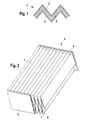
- FIG. 1 shows a section through a filter medium, consisting of two zig-zag folded filter webs and trapped adsorptive particles and
- Figure 2 is a schematic representation of a filter element with sealed lateral edges of the filter medium.
- FIG. 1 shows a section through a filter medium 1 which can be used for example in an air filter for the intake tract of an internal combustion engine or for a vehicle cabin interior air filter.
- a filter medium 1 which can be used for example in an air filter for the intake tract of an internal combustion engine or for a vehicle cabin interior air filter.
- FIG. 2 shows a filter element 5 in which a frame part 6 is present here in the lateral edge region, which mechanically holds the filter medium 1 at lateral edges 7 of the filter medium 1.
- a sealing mass 8 indicated here by dashed lines is provided, which here is, for example, a wax which can be liquefied by heat and hardened by cooling.
- a sealing mass 8 is, for example, a wax which can be liquefied by heat and hardened by cooling.
- the zig-zag folded and cut into the required dimensions filter medium 1 are held and then applied with a suitably designed gun as Leimdüse or ladle first soft sealing compound 8, which in a small Depth penetrates into the filter medium 1.
- a suitably designed gun as Leimdüse or ladle first soft sealing compound 8, which in a small Depth penetrates into the filter medium 1.
- the frame part 6 is then sprayed on laterally in a plastic injection molding device.
Landscapes
- Chemical & Material Sciences (AREA)
- Chemical Kinetics & Catalysis (AREA)
- Filtering Materials (AREA)
- Solid-Sorbent Or Filter-Aiding Compositions (AREA)
- Filtering Of Dispersed Particles In Gases (AREA)
Abstract
Description
- Die Erfindung betrifft ein Filter- oder Adsorberelement, insbesondere für die Reinigung von Luft in Kraftfahrzeugen, nach der Gattung des Hauptanspruchs.
- Es ist beispielsweise aus der
EP 0759319 A 26.02.1997 ein Filterelement bekannt, bei dem das Filtermedium eine durchgehende Zick-Zack-Faltung aufweist und aus einem Bahnenmaterial hergestellt ist, das mit einem seitlichen Abschluss versehen ist. Bei diesem bekannten Filterelement werden bereits bei der Herstellung des Endlosbandes mit den gefalteten Filterbahnen ein ebenfalls endloser Dichtungsstreifen als Rahmenteil seitlich angefügt. Nach dem Zuschnitt der erforderlichen Länge der Filterbahnen werden stirnseitig U-Profilleisten derart an die seitlichen Dichtungsstreifen angefügt, dass aus den U-Profilen und den seitlichen Dichtstreifen ein steifer Rahmen für den Filtereinsatz und damit das Filterelement gebildet ist. - Weiterhin ist aus der
DE 202005011726 U 27.10.2005 bekannt, dass ein Filtereinsatz mit durchgehender Zick-Zack-Faltung für ein Filterelement als sogenanntes Kombinationsfilter, insbesondere als Filter- und Adsorberelement, aufgebaut ist, bei dem Partikel mit guten Adsorptionseigenschaften, wie zum Beispiel Aktivkohle, zwischen zwei Lagen von Filterbahnen eingefasst sind. Hier werden an den Stirnseiten des Filtermediums, also bei den jeweiligen Endfaltungen mittels der Verklebung dieser Endfaltungen an einem Profilelement als Rahmen durch den Kleber die Filterbahnen und die eingefassten Partikeln mit versiegelt, so dass hier durch diese Versiegelung verhindert wird, dass die Partikel aus den Lagen der Filterbahnen herausrieseln. - Die Erfindung betrifft ein Filter- oder Adsorberelement der eingangs genannten Art mit mindestens zwei Lagen von Filterbahnen und einer von den Lagen der Filterbahnen weitgehend eingefassten Schicht aus adsorptiven Partikeln. Gemäß der Erfindung sind in vorteilhafter Weise die seitlichen offenen Ränder der Filterbahnen mit den eingefassten adsorptiven Partikeln zumindest für den Herstellungsprozess des Filterelements mit einer dichtenden Masse versiegelt. Bevorzugt sind hierbei die Lagen der Filterbahnen zick-zack-förmig gefaltet.
- Die adsorptiven Partikel können beispielsweise aus Aktivkohlepartikel gebildet sein, es sind hier aber auch andere saugfähige Materialien einsetzbar. Beispielsweise sind auch lonentauscher, insbesondere lonentauscherharze oder vergleichbare Materialien hier einsetzbar.
- Die dichtende Masse kann in vorteilhafter Weise ein durch Hitze verflüssigbares und durch Auskühlung härtbares Wachs sein oder es kann auch ein Kleber oder eine andere vergleichbare Substanzen verwendet werden. Andererseits kann die dichtende Masse auch dadurch gebildet werden, dass mittels thermischer (Heizung, Laser, etc) oder chemischer Verfahren (Ätzung) der Randbereich der Lagen der Filterbahnen aufgeweicht oder aufgeschmolzen wird.
- Bei einem erfindungsgemäßen Verfahren zur Herstellung des vorhergehend beschriebenen Filterelements werden die zick-zack-förmig gefalteten und in den erforderlichen Abmessungen geschnittenen Lagen von Filterbahnen mit der eingefassten Schicht aus adsorptiven Partikeln in einer Vorrichtung gehalten, die einen Auftragskopf zur Auf- oder Einbringung der weichen Masse aufweist. Nach dem Auf- oder Einbringung der weichen Masse wird in vorteilhafter Weise in einer Kunststoffspritzgussvorrichtung das Rahmenteil seitlich aufgespritzt.
- Mit dem Auftragskopf kann beispielsweise über eine Düse erhitztes Wachs auf die seitlichen Randbereiche der Lagen dosiert aufgespritzt werden oder es ist alternativ möglich, dass die seitlichen Randbereiche der Filterbahnen mit erhitztem Wachs dadurch versehen werden, dass eine Schöpfkelle als Auftragskopf die seitlichen Randbereiche des Filtermediums mit erhitztem Wachs benetzt.
- Diese erfindungsgemäße Vorkonfektionierung des Filtermediums zur Herstellung eines Filterelements mit beispielsweise Aktivkohlemedien erfolgt in der Regel im Anschluss an eine sogenannte Messerfaltanlage zur Herstellung der Zick-Zack-Faltung und nach einem Trennschnitt. Das Versiegeln der somit entstandenen Schnittkante kann dann durch Auftragen der zunächst weichen dichtenden Masse mittels des Auftragskopfes, zum Beispiel einer Leimdüse, erfolgen, wobei die Auftragsmenge über die Düse des Auftragskopfes geregelt wird und die Eindringtiefe des Wachses über die Auftragsmenge gesteuert wird.
- Bei der alternativen Möglichkeit mittels der Schöpfkelle wird das Wachs quasi mit einem Tauchverfahrens aufgebracht. Hierzu werden die Endfalten der zu versiegelnden Filterbahnen in der Vorrichtung zur Versiegelung fixiert und anschließend fährt die Schöpfkelle hoch und benetzt die Kanten der Filterbahnen.
- Mit der Erfindung können auf einfache Weise eine Reihe von Schwierigkeiten insbesondere bei der Kunststoffumspritzung zur Herstellung der Rahmenteile für das Filterelement in ihrer Auswirkung gemindert werden. Bei der Herstellung von Filterelementen der zuvor beschriebenen Art, die auch als Kombifilter in plissierter Form bezeichnet werden, entstehen Probleme dadurch, dass bei der Einspritzung in einen Kunststoffrahmen beim Schließen der Spritzgussform eventuell das Filtermedium (Filterbahnen und eingeschlossene Partikel) zerstört wird bzw. die Partikel (Aktivkohle oder vergleichbares Material) gebrochen werden. Hierbei entsteht Staub, der aus dem Filtermedium herausfällt. Gestaltet man andererseits den Dichtspalt in der Spritzgießform zu offen, dringt der eingespritzte Kunststoff zu weit in das Filtermedium ein und es erfolgt ein sogenanntes Überspritzen.
- Um dieses zu verhindern werden die erfindungsgemäßen Versiegelungen vorgeschlagen, bei der die Schnittkanten vor dem Einbringen in die Spritzgießform versiegelt werden. Hierdurch wird der Randbereich des plissierten Filtermediums weitgehend verschlossen und die Spritzgießform kann ohne negative Auswirkungen geschlossen werden, wobei die weiche Masse ausweichen kann, ohne dass die Partikel zerstört werden. Beim Einspritzvorgang wird dann ein Überspritzen weitgehend verhindert.
- Ein Ausführungsbeispiel der Erfindung wird anhand der Zeichnungen erläutert. Es zeigen:
- Figur 1 einen Schnitt durch ein Filtermedium, bestehend aus zwei zick-zack-förmig gefalteten Filterbahnen und eingeschlossenen adsorptiven Partikeln und
- Figur 2 eine schematische Darstellung eines Filterelements mit versiegelten seitlichen Rändern des Filtermediums.
- Weg(e) zur Ausführung der Erfindung
- In Figur 1 ist ein Schnitt durch ein Filtermedium 1gezeigt, das beispielsweise in einem Luftfilter für den Ansaugtrakt eines Verbrennungsmotors oder für einen Fahrzeugkabinen-Innenraumluftfilter angewendet werden kann. Es sind Lagen von zick-zack-förmig gefalteten Filterbahnen 2 und 3 vorhanden, zwischen den eine Schicht aus adsorptiven Partikeln 4, hier Aktivkohle, eingefasst ist.
- Aus Figur 2 ist ein Filterelement 5 zu entnehmen, bei dem hier im seitlichen Randbereich ein Rahmenteil 6 vorhanden ist, welches das Filtermedium 1 an seitlichen Rändern 7 des Filtermediums 1 mechanisch festhält.
- An den seitlichen Rändern 7 des Filtermediums 1 ist eine hier gestrichelt angedeutete dichtende Masse 8 angebracht, die hier beispielsweise ein durch Hitze verflüssigbares und durch Auskühlung härtbares Wachs ist. Es sind aber auch die in den vorangehenden Beschreibungsteilen erwähnten Materialien und Verfahren einsetzbar.
- In einer hier nicht dargestellten Vorrichtung zur Herstellung des Filterelements 5 werden das zick-zack-förmig gefaltete und in den erforderlichen Abmessungen geschnittene Filtermedium 1gehalten und dann mit einem entsprechend gestalteten Auftragskopf als Leimdüse oder Schöpfkelle die zunächst weiche dichtende Masse 8 aufgetragen, die in einer geringen Tiefe in das Filtermedium 1 eindringt. Nach dem Auf- oder Einbringung der Masse 8 wird dann in einer Kunststoffspritzgussvorrichtung das Rahmenteil 6 seitlich aufgespritzt.
Claims (13)
- Filter- oder Adsorberelement (5), bestehend aus einem Filtermedium (1) mit mindestens zwei Lagen von Filterbahnen (2,3) und einer von den Filterbahnen (2,3) weitgehend eingefassten Schicht aus adsorptiven Partikeln (4), dadurch gekennzeichnet, dass die seitlichen offenen Ränder (7) des Filtermediums (1) mit den eingefassten adsorptiven Partikeln (4) zumindest für Herstellungsprozess des Filterelements (5) mit einer dichtenden Masse (8) versiegelt sind.
- Filter- oder Adsorberelement nach Anspruch ,1 bestehend aus mindestens zwei zick-zack-förmig gefalteten Lagen von Filterbahnen (2,3).
- Filter- oder Adsorberelement nach Anspruch 2, dadurch gekennzeichnet, dass zumindest an den seitlichen Rändern ein festes Rahmenteil (6) angefügt ist.
- Filter- oder Adsorberelement nach Anspruch 3, dadurch gekennzeichnet, dass das feste Rahmenteil (6) ein Kunststoffspritzgussteil ist.
- Filter- oder Adsorberelement nach einem der vorhergehenden Ansprüche, dadurch gekennzeichnet, dass die adsorptiven Partikel (4) aus Aktivkohlepartikel gebildet sind.
- Filter- oder Adsorberelement nach einem der vorhergehenden Ansprüche, dadurch gekennzeichnet, dass die adsorptiven Partikel (4) aus lonentauschern, insbesondere aus lonentauscherharzen gebildet sind.
- Filter- oder Adsorberelement nach einem der vorhergehenden Ansprüche, dadurch gekennzeichnet, dass die dichtende Masse (8) ein durch Hitze verflüssigbares und durch Auskühlung härtbares Wachs ist.
- Filter- oder Adsorberelement nach einem der Ansprüche 1 bis 6, dadurch gekennzeichnet, dass die dichtende Masse (8) ein Kleber ist.
- Filter- oder Adsorberelement nach einem der Ansprüche 1 bis 6, dadurch gekennzeichnet, dass die dichtende Masse (8) durch einen mittels thermischer oder chemischer Verfahren aufweich- oder aufschmelzbaren Randbereich der Filterbahnen (2,3) erzeugbar ist.
- Verfahren zur Herstellung eines Filter- oder Adsorberelements nach einem der Ansprüche 2 bis 9, dadurch gekennzeichnet, dass die zick-zack-förmig gefalteten und in den erforderlichen Abmessungen geschnittenen Lagen von Filterbahnen (2,3) mit der eingefassten Schicht aus adsorptiven Partikeln (4) in einer Vorrichtung gehalten wird, die einen Auftragskopf zur Auf- oder Einbringung der dichtenden Masse (8) aufweist und dass nach dem Auf- oder Einbringung der dichtenden Masse (8) in einer Kunststoffspritzgussvorrichtung das Rahmenteil (6) seitlich aufgespritzt wird.
- Verfahren nach Anspruch 10, dadurch gekennzeichnet, dass mit dem Auftragskopf über eine Düse erhitztes Wachs auf die seitlichen Ränder (7) des Filtermediums (1) dosiert aufgespritzt wird.
- Verfahren nach Anspruch 10, dadurch gekennzeichnet, dass die seitlichen Ränder (7) des Filtermediums (1) mit erhitztem Wachs dadurch versehen werden, dass eine Schöpfkelle als Auftragskopf die seitlichen Ränder (7) des Filtermediums (1) mit erhitztem Wachs benetzt.
- Verfahren zur Herstellung eines Filter- oder Adsorberelement (5), umfassend ein Filtermedium (1) mit mindestens zwei Lagen von Filterbahnen (2,3) und einer von den Filterbahnen (2,3) weitgehend eingefassten Schicht aus adsorptiven Partikeln (4), dadurch gekennzeichnet, dass die seitlichen offenen Ränder (7) des Filtermediums (1) mit den eingefassten adsorptiven Partikeln (4) vor dem Anbringen eines Rahmenteils mit einer dichtenden Masse (8) versiegelt sind.
Applications Claiming Priority (1)
| Application Number | Priority Date | Filing Date | Title |
|---|---|---|---|
| DE102006043729A DE102006043729A1 (de) | 2006-09-13 | 2006-09-13 | Filter- oder Adsorberelement mit eingeschlossenen Adsorptionspartikeln und ein Verfahren zu dessen Herstellung |
Publications (2)
| Publication Number | Publication Date |
|---|---|
| EP1900413A1 true EP1900413A1 (de) | 2008-03-19 |
| EP1900413B1 EP1900413B1 (de) | 2010-11-10 |
Family
ID=38792730
Family Applications (1)
| Application Number | Title | Priority Date | Filing Date |
|---|---|---|---|
| EP07116181A Not-in-force EP1900413B1 (de) | 2006-09-13 | 2007-09-12 | Filter- oder Adsorberelement mit eingeschlossenen Adsorptionspartikeln und ein Verfahren zu dessen Herstellung |
Country Status (4)
| Country | Link |
|---|---|
| US (1) | US20080060524A1 (de) |
| EP (1) | EP1900413B1 (de) |
| AT (1) | ATE487527T1 (de) |
| DE (2) | DE102006043729A1 (de) |
Cited By (2)
| Publication number | Priority date | Publication date | Assignee | Title |
|---|---|---|---|---|
| WO2017220691A1 (de) * | 2016-06-21 | 2017-12-28 | Mann+Hummel Gmbh | Filterelement, filteranordnung und verfahren |
| EP2895251B1 (de) | 2012-09-12 | 2018-12-26 | Camfil AB | Filteranordnung und filteranordnungherstellungsverfahren |
Families Citing this family (13)
| Publication number | Priority date | Publication date | Assignee | Title |
|---|---|---|---|---|
| US7645329B2 (en) * | 2007-10-31 | 2010-01-12 | Advanced Flow Engineering, Inc. | Composite air/hydrocarbon trap filter assembly |
| DE102009049156A1 (de) * | 2009-10-12 | 2011-04-21 | Mahle International Gmbh | Luftfilter |
| US8677966B2 (en) | 2011-01-20 | 2014-03-25 | Advanced Flow Engineering, Inc. | Air intake flow device and system |
| EP3903906B1 (de) * | 2012-07-11 | 2023-06-21 | MANN+HUMMEL GmbH | Verfahren zur reinigung von luft |
| US9440175B2 (en) | 2012-11-01 | 2016-09-13 | Advanced Flow Engineering, Inc. | Interface air filter and assembly |
| US9605626B2 (en) * | 2015-03-06 | 2017-03-28 | Deere & Company | Siloxane filtration system and method |
| ITUB20159777A1 (it) * | 2015-12-30 | 2017-06-30 | Bmc Srl | Filtro aria provvisto di un dispositivo riscaldatore |
| JP6571566B2 (ja) * | 2016-03-17 | 2019-09-04 | 三菱製紙株式会社 | 脱臭フィルタ |
| CA3137990A1 (en) | 2019-06-21 | 2020-12-24 | Climeworks Ag | Adsorber structure for gas separation processes |
| US10926209B1 (en) * | 2020-06-05 | 2021-02-23 | Celios Corporation | Air filtration system, air filtration device, and air filtration module for use therewith |
| DE102022132792A1 (de) * | 2022-12-09 | 2024-06-20 | Vaillant Gmbh | Adsorberpartitionierung |
| DE102022132800A1 (de) * | 2022-12-09 | 2024-06-20 | Vaillant Gmbh | Adsorptionsvorrichtung |
| WO2025031905A1 (en) | 2023-08-07 | 2025-02-13 | Climeworks Ag | Modular adsorber structure for gas separation processes |
Citations (6)
| Publication number | Priority date | Publication date | Assignee | Title |
|---|---|---|---|---|
| EP0759319A1 (de) | 1995-08-18 | 1997-02-26 | Knecht Filterwerke Gmbh | Plattenförmiger Filtereinsatz und Verfahren zu seiner Herstellung |
| DE19844874A1 (de) | 1998-09-30 | 2000-04-06 | Knecht Filterwerke Gmbh | Plattenfilterelement für ein Luftfilter |
| DE10049537A1 (de) * | 2000-10-07 | 2002-04-11 | Mahle Filtersysteme Gmbh | Kraftstofftank-Entlüftungsanlage |
| DE10249577A1 (de) | 2002-10-24 | 2004-05-13 | Helsa-Werke Helmut Sandler Gmbh & Co. Kg | Filterelement |
| DE202005011726U1 (de) | 2005-03-11 | 2005-09-22 | Helsa-Automotive Gmbh & Co. Kg | Filterelement |
| US7070641B1 (en) | 2003-12-03 | 2006-07-04 | Fleetguard, Inc. | Carbon media filter element |
Family Cites Families (5)
| Publication number | Priority date | Publication date | Assignee | Title |
|---|---|---|---|---|
| US4617122A (en) * | 1984-08-01 | 1986-10-14 | Donaldson Company, Inc. | Crimp seal pleated filter assembly |
| DE10026902A1 (de) * | 2000-05-31 | 2002-04-18 | Sandler Helmut Helsa Werke | Filter insbesondere für ein Fahrzeug |
| DE10324341B3 (de) * | 2003-05-27 | 2005-02-24 | Carl Freudenberg Kg | Verfahren zum Reinigen eines durchströmenden Mediums |
| JP4593224B2 (ja) * | 2004-03-30 | 2010-12-08 | ニチアス株式会社 | ケミカルフィルター及びその製造方法 |
| DE202005011733U1 (de) * | 2005-03-21 | 2005-09-29 | Helsa-Automotive Gmbh & Co. Kg | Filterelement |
-
2006
- 2006-09-13 DE DE102006043729A patent/DE102006043729A1/de not_active Withdrawn
-
2007
- 2007-09-12 DE DE502007005598T patent/DE502007005598D1/de active Active
- 2007-09-12 EP EP07116181A patent/EP1900413B1/de not_active Not-in-force
- 2007-09-12 AT AT07116181T patent/ATE487527T1/de active
- 2007-09-12 US US11/854,084 patent/US20080060524A1/en not_active Abandoned
Patent Citations (6)
| Publication number | Priority date | Publication date | Assignee | Title |
|---|---|---|---|---|
| EP0759319A1 (de) | 1995-08-18 | 1997-02-26 | Knecht Filterwerke Gmbh | Plattenförmiger Filtereinsatz und Verfahren zu seiner Herstellung |
| DE19844874A1 (de) | 1998-09-30 | 2000-04-06 | Knecht Filterwerke Gmbh | Plattenfilterelement für ein Luftfilter |
| DE10049537A1 (de) * | 2000-10-07 | 2002-04-11 | Mahle Filtersysteme Gmbh | Kraftstofftank-Entlüftungsanlage |
| DE10249577A1 (de) | 2002-10-24 | 2004-05-13 | Helsa-Werke Helmut Sandler Gmbh & Co. Kg | Filterelement |
| US7070641B1 (en) | 2003-12-03 | 2006-07-04 | Fleetguard, Inc. | Carbon media filter element |
| DE202005011726U1 (de) | 2005-03-11 | 2005-09-22 | Helsa-Automotive Gmbh & Co. Kg | Filterelement |
Cited By (2)
| Publication number | Priority date | Publication date | Assignee | Title |
|---|---|---|---|---|
| EP2895251B1 (de) | 2012-09-12 | 2018-12-26 | Camfil AB | Filteranordnung und filteranordnungherstellungsverfahren |
| WO2017220691A1 (de) * | 2016-06-21 | 2017-12-28 | Mann+Hummel Gmbh | Filterelement, filteranordnung und verfahren |
Also Published As
| Publication number | Publication date |
|---|---|
| ATE487527T1 (de) | 2010-11-15 |
| DE102006043729A1 (de) | 2008-03-27 |
| US20080060524A1 (en) | 2008-03-13 |
| EP1900413B1 (de) | 2010-11-10 |
| DE502007005598D1 (de) | 2010-12-23 |
Similar Documents
| Publication | Publication Date | Title |
|---|---|---|
| EP1900413B1 (de) | Filter- oder Adsorberelement mit eingeschlossenen Adsorptionspartikeln und ein Verfahren zu dessen Herstellung | |
| EP0438639B1 (de) | Verfahren zur Herstellung eines als Faltenpack ausgebildeten Filtereinsatzes aus Vliesstoff | |
| EP3471855B1 (de) | Filterelement, filteranordnung und verfahren | |
| EP0645170B1 (de) | Filtereinsatz und Verfahren zur Herstellung eines Filtereinsatzes | |
| DE4345129A1 (de) | Verfahren zur Herstellung eines Fluidfilters | |
| EP1522472B1 (de) | Wischerblatt | |
| EP2919966B1 (de) | Verfahren zur herstellung eines formkörpers mit superhydrophober oberfläche | |
| EP2334399A1 (de) | Verfahren zum herstellen einer filterendscheibe und eines fluidfilters, filterendscheibe | |
| DE4323136A1 (de) | Filtereinsatz | |
| DE10233888A1 (de) | Verfahren zur Herstellung eines Polyurethanschaumformteils mit integriertem Insert und Aufschäumform dafür | |
| EP0623377B1 (de) | Filterelement | |
| DE102013014688A1 (de) | Filterelement und Verfahren zum Herstellen desselben | |
| EP2027904A2 (de) | Filterelement mit Dichtung und Verfahren zur Herstellung des Filterelements | |
| DE102014015905A1 (de) | Flachfilterelement für Fluide und Verfahren und Vorrichtung zur Herstellung eines solchen | |
| DE3506202A1 (de) | Verfahren zur reinigung und zur instandsetzung von vielfach-isolierverglasungen, hauptsaechlich bestimmt fuer die verglasungen von bauten, und die mittel zur anwendung des verfahrens | |
| EP0887118A2 (de) | Verfahren und Vorrichtung zur Reparatur kleiner Lackfehler in Lackschichten | |
| EP1779916B1 (de) | Extrudierte Dichtung | |
| DE102016217458A1 (de) | Plissierter Gasfiltereinsatz für ein Kraftfahrzeug mit diskontinuierlich verklebten Filtermaterialschenkeln sowie Verfahren und Vorrichtung zu dessen Herstellung | |
| DE102015014017A1 (de) | Partikelfilter sowie Verfahren zu dessen Herstellung | |
| DE102004064184B4 (de) | Filteranordnung und ein Verfahren zu deren Herstellung | |
| DE102015225668A1 (de) | Verfahren zur Herstellung eines Kapillarmembranbündels | |
| DE3229014C1 (de) | Verfahren zum Beschichten der Oberflaechen von Pappenzuschnitten | |
| DE10141524A1 (de) | Stoff- und Wärmeaustauscherfläche | |
| DE102014014008A1 (de) | Filterelement mit Filterbalg | |
| DE112013004737T5 (de) | Verfahren zur Bildung geklebter Strukturen und hierdurch gebildete geklebte Strukturen |
Legal Events
| Date | Code | Title | Description |
|---|---|---|---|
| PUAI | Public reference made under article 153(3) epc to a published international application that has entered the european phase |
Free format text: ORIGINAL CODE: 0009012 |
|
| AK | Designated contracting states |
Kind code of ref document: A1 Designated state(s): AT BE BG CH CY CZ DE DK EE ES FI FR GB GR HU IE IS IT LI LT LU LV MC MT NL PL PT RO SE SI SK TR |
|
| AX | Request for extension of the european patent |
Extension state: AL BA HR MK YU |
|
| 17P | Request for examination filed |
Effective date: 20080331 |
|
| 17Q | First examination report despatched |
Effective date: 20080506 |
|
| AKX | Designation fees paid |
Designated state(s): AT BE BG CH CY CZ DE DK EE ES FI FR GB GR HU IE IS IT LI LT LU LV MC MT NL PL PT RO SE SI SK TR |
|
| GRAP | Despatch of communication of intention to grant a patent |
Free format text: ORIGINAL CODE: EPIDOSNIGR1 |
|
| GRAS | Grant fee paid |
Free format text: ORIGINAL CODE: EPIDOSNIGR3 |
|
| GRAA | (expected) grant |
Free format text: ORIGINAL CODE: 0009210 |
|
| AK | Designated contracting states |
Kind code of ref document: B1 Designated state(s): AT BE BG CH CY CZ DE DK EE ES FI FR GB GR HU IE IS IT LI LT LU LV MC MT NL PL PT RO SE SI SK TR |
|
| REG | Reference to a national code |
Ref country code: GB Ref legal event code: FG4D Free format text: NOT ENGLISH |
|
| REG | Reference to a national code |
Ref country code: CH Ref legal event code: EP |
|
| REG | Reference to a national code |
Ref country code: IE Ref legal event code: FG4D Free format text: LANGUAGE OF EP DOCUMENT: GERMAN |
|
| REF | Corresponds to: |
Ref document number: 502007005598 Country of ref document: DE Date of ref document: 20101223 Kind code of ref document: P |
|
| REG | Reference to a national code |
Ref country code: NL Ref legal event code: VDEP Effective date: 20101110 |
|
| LTIE | Lt: invalidation of european patent or patent extension |
Effective date: 20101110 |
|
| PG25 | Lapsed in a contracting state [announced via postgrant information from national office to epo] |
Ref country code: LT Free format text: LAPSE BECAUSE OF FAILURE TO SUBMIT A TRANSLATION OF THE DESCRIPTION OR TO PAY THE FEE WITHIN THE PRESCRIBED TIME-LIMIT Effective date: 20101110 |
|
| PG25 | Lapsed in a contracting state [announced via postgrant information from national office to epo] |
Ref country code: SI Free format text: LAPSE BECAUSE OF FAILURE TO SUBMIT A TRANSLATION OF THE DESCRIPTION OR TO PAY THE FEE WITHIN THE PRESCRIBED TIME-LIMIT Effective date: 20101110 Ref country code: PT Free format text: LAPSE BECAUSE OF FAILURE TO SUBMIT A TRANSLATION OF THE DESCRIPTION OR TO PAY THE FEE WITHIN THE PRESCRIBED TIME-LIMIT Effective date: 20110310 Ref country code: SE Free format text: LAPSE BECAUSE OF FAILURE TO SUBMIT A TRANSLATION OF THE DESCRIPTION OR TO PAY THE FEE WITHIN THE PRESCRIBED TIME-LIMIT Effective date: 20101110 Ref country code: IS Free format text: LAPSE BECAUSE OF FAILURE TO SUBMIT A TRANSLATION OF THE DESCRIPTION OR TO PAY THE FEE WITHIN THE PRESCRIBED TIME-LIMIT Effective date: 20110310 Ref country code: NL Free format text: LAPSE BECAUSE OF FAILURE TO SUBMIT A TRANSLATION OF THE DESCRIPTION OR TO PAY THE FEE WITHIN THE PRESCRIBED TIME-LIMIT Effective date: 20101110 Ref country code: FI Free format text: LAPSE BECAUSE OF FAILURE TO SUBMIT A TRANSLATION OF THE DESCRIPTION OR TO PAY THE FEE WITHIN THE PRESCRIBED TIME-LIMIT Effective date: 20101110 Ref country code: LV Free format text: LAPSE BECAUSE OF FAILURE TO SUBMIT A TRANSLATION OF THE DESCRIPTION OR TO PAY THE FEE WITHIN THE PRESCRIBED TIME-LIMIT Effective date: 20101110 Ref country code: BG Free format text: LAPSE BECAUSE OF FAILURE TO SUBMIT A TRANSLATION OF THE DESCRIPTION OR TO PAY THE FEE WITHIN THE PRESCRIBED TIME-LIMIT Effective date: 20110210 Ref country code: CY Free format text: LAPSE BECAUSE OF FAILURE TO SUBMIT A TRANSLATION OF THE DESCRIPTION OR TO PAY THE FEE WITHIN THE PRESCRIBED TIME-LIMIT Effective date: 20101110 |
|
| REG | Reference to a national code |
Ref country code: IE Ref legal event code: FD4D |
|
| PG25 | Lapsed in a contracting state [announced via postgrant information from national office to epo] |
Ref country code: GR Free format text: LAPSE BECAUSE OF FAILURE TO SUBMIT A TRANSLATION OF THE DESCRIPTION OR TO PAY THE FEE WITHIN THE PRESCRIBED TIME-LIMIT Effective date: 20110211 |
|
| PG25 | Lapsed in a contracting state [announced via postgrant information from national office to epo] |
Ref country code: ES Free format text: LAPSE BECAUSE OF FAILURE TO SUBMIT A TRANSLATION OF THE DESCRIPTION OR TO PAY THE FEE WITHIN THE PRESCRIBED TIME-LIMIT Effective date: 20110221 Ref country code: IE Free format text: LAPSE BECAUSE OF FAILURE TO SUBMIT A TRANSLATION OF THE DESCRIPTION OR TO PAY THE FEE WITHIN THE PRESCRIBED TIME-LIMIT Effective date: 20101110 Ref country code: EE Free format text: LAPSE BECAUSE OF FAILURE TO SUBMIT A TRANSLATION OF THE DESCRIPTION OR TO PAY THE FEE WITHIN THE PRESCRIBED TIME-LIMIT Effective date: 20101110 Ref country code: CZ Free format text: LAPSE BECAUSE OF FAILURE TO SUBMIT A TRANSLATION OF THE DESCRIPTION OR TO PAY THE FEE WITHIN THE PRESCRIBED TIME-LIMIT Effective date: 20101110 |
|
| PG25 | Lapsed in a contracting state [announced via postgrant information from national office to epo] |
Ref country code: PL Free format text: LAPSE BECAUSE OF FAILURE TO SUBMIT A TRANSLATION OF THE DESCRIPTION OR TO PAY THE FEE WITHIN THE PRESCRIBED TIME-LIMIT Effective date: 20101110 Ref country code: RO Free format text: LAPSE BECAUSE OF FAILURE TO SUBMIT A TRANSLATION OF THE DESCRIPTION OR TO PAY THE FEE WITHIN THE PRESCRIBED TIME-LIMIT Effective date: 20101110 Ref country code: SK Free format text: LAPSE BECAUSE OF FAILURE TO SUBMIT A TRANSLATION OF THE DESCRIPTION OR TO PAY THE FEE WITHIN THE PRESCRIBED TIME-LIMIT Effective date: 20101110 Ref country code: DK Free format text: LAPSE BECAUSE OF FAILURE TO SUBMIT A TRANSLATION OF THE DESCRIPTION OR TO PAY THE FEE WITHIN THE PRESCRIBED TIME-LIMIT Effective date: 20101110 |
|
| PLBE | No opposition filed within time limit |
Free format text: ORIGINAL CODE: 0009261 |
|
| STAA | Information on the status of an ep patent application or granted ep patent |
Free format text: STATUS: NO OPPOSITION FILED WITHIN TIME LIMIT |
|
| 26N | No opposition filed |
Effective date: 20110811 |
|
| REG | Reference to a national code |
Ref country code: DE Ref legal event code: R097 Ref document number: 502007005598 Country of ref document: DE Effective date: 20110811 |
|
| PG25 | Lapsed in a contracting state [announced via postgrant information from national office to epo] |
Ref country code: IT Free format text: LAPSE BECAUSE OF FAILURE TO SUBMIT A TRANSLATION OF THE DESCRIPTION OR TO PAY THE FEE WITHIN THE PRESCRIBED TIME-LIMIT Effective date: 20101110 |
|
| BERE | Be: lapsed |
Owner name: MANN+HUMMEL G.M.B.H. Effective date: 20110930 |
|
| PG25 | Lapsed in a contracting state [announced via postgrant information from national office to epo] |
Ref country code: MC Free format text: LAPSE BECAUSE OF NON-PAYMENT OF DUE FEES Effective date: 20110930 |
|
| REG | Reference to a national code |
Ref country code: CH Ref legal event code: PL |
|
| GBPC | Gb: european patent ceased through non-payment of renewal fee |
Effective date: 20110912 |
|
| PG25 | Lapsed in a contracting state [announced via postgrant information from national office to epo] |
Ref country code: BE Free format text: LAPSE BECAUSE OF NON-PAYMENT OF DUE FEES Effective date: 20110930 |
|
| PG25 | Lapsed in a contracting state [announced via postgrant information from national office to epo] |
Ref country code: LI Free format text: LAPSE BECAUSE OF NON-PAYMENT OF DUE FEES Effective date: 20110930 Ref country code: CH Free format text: LAPSE BECAUSE OF NON-PAYMENT OF DUE FEES Effective date: 20110930 |
|
| PG25 | Lapsed in a contracting state [announced via postgrant information from national office to epo] |
Ref country code: GB Free format text: LAPSE BECAUSE OF NON-PAYMENT OF DUE FEES Effective date: 20110912 |
|
| PG25 | Lapsed in a contracting state [announced via postgrant information from national office to epo] |
Ref country code: MT Free format text: LAPSE BECAUSE OF FAILURE TO SUBMIT A TRANSLATION OF THE DESCRIPTION OR TO PAY THE FEE WITHIN THE PRESCRIBED TIME-LIMIT Effective date: 20101110 |
|
| PG25 | Lapsed in a contracting state [announced via postgrant information from national office to epo] |
Ref country code: LU Free format text: LAPSE BECAUSE OF NON-PAYMENT OF DUE FEES Effective date: 20110912 |
|
| PG25 | Lapsed in a contracting state [announced via postgrant information from national office to epo] |
Ref country code: TR Free format text: LAPSE BECAUSE OF FAILURE TO SUBMIT A TRANSLATION OF THE DESCRIPTION OR TO PAY THE FEE WITHIN THE PRESCRIBED TIME-LIMIT Effective date: 20101110 |
|
| PG25 | Lapsed in a contracting state [announced via postgrant information from national office to epo] |
Ref country code: HU Free format text: LAPSE BECAUSE OF FAILURE TO SUBMIT A TRANSLATION OF THE DESCRIPTION OR TO PAY THE FEE WITHIN THE PRESCRIBED TIME-LIMIT Effective date: 20101110 |
|
| REG | Reference to a national code |
Ref country code: AT Ref legal event code: MM01 Ref document number: 487527 Country of ref document: AT Kind code of ref document: T Effective date: 20120912 |
|
| PG25 | Lapsed in a contracting state [announced via postgrant information from national office to epo] |
Ref country code: AT Free format text: LAPSE BECAUSE OF NON-PAYMENT OF DUE FEES Effective date: 20120912 |
|
| REG | Reference to a national code |
Ref country code: FR Ref legal event code: PLFP Year of fee payment: 10 |
|
| REG | Reference to a national code |
Ref country code: FR Ref legal event code: PLFP Year of fee payment: 11 |
|
| REG | Reference to a national code |
Ref country code: DE Ref legal event code: R081 Ref document number: 502007005598 Country of ref document: DE Owner name: MANN+HUMMEL GMBH, DE Free format text: FORMER OWNER: MANN + HUMMEL GMBH, 71638 LUDWIGSBURG, DE |
|
| REG | Reference to a national code |
Ref country code: FR Ref legal event code: PLFP Year of fee payment: 12 |
|
| PGFP | Annual fee paid to national office [announced via postgrant information from national office to epo] |
Ref country code: FR Payment date: 20200914 Year of fee payment: 14 Ref country code: DE Payment date: 20200925 Year of fee payment: 14 |
|
| REG | Reference to a national code |
Ref country code: DE Ref legal event code: R119 Ref document number: 502007005598 Country of ref document: DE |
|
| PG25 | Lapsed in a contracting state [announced via postgrant information from national office to epo] |
Ref country code: FR Free format text: LAPSE BECAUSE OF NON-PAYMENT OF DUE FEES Effective date: 20210930 Ref country code: DE Free format text: LAPSE BECAUSE OF NON-PAYMENT OF DUE FEES Effective date: 20220401 |