EP1900410A2 - Filter and manufacturing method therefor - Google Patents
Filter and manufacturing method therefor Download PDFInfo
- Publication number
- EP1900410A2 EP1900410A2 EP07114449A EP07114449A EP1900410A2 EP 1900410 A2 EP1900410 A2 EP 1900410A2 EP 07114449 A EP07114449 A EP 07114449A EP 07114449 A EP07114449 A EP 07114449A EP 1900410 A2 EP1900410 A2 EP 1900410A2
- Authority
- EP
- European Patent Office
- Prior art keywords
- case member
- holding frame
- joining
- filter
- filter element
- Prior art date
- Legal status (The legal status is an assumption and is not a legal conclusion. Google has not performed a legal analysis and makes no representation as to the accuracy of the status listed.)
- Withdrawn
Links
- 238000004519 manufacturing process Methods 0.000 title claims description 9
- 238000005304 joining Methods 0.000 claims abstract description 168
- 229920003002 synthetic resin Polymers 0.000 claims abstract description 45
- 239000000057 synthetic resin Substances 0.000 claims abstract description 45
- 238000001914 filtration Methods 0.000 claims abstract description 26
- 230000002093 peripheral effect Effects 0.000 claims abstract description 16
- 239000000463 material Substances 0.000 claims description 39
- 230000035699 permeability Effects 0.000 claims description 19
- 238000003466 welding Methods 0.000 description 27
- 239000003921 oil Substances 0.000 description 8
- 230000000694 effects Effects 0.000 description 6
- -1 polypropylene Polymers 0.000 description 3
- 239000000047 product Substances 0.000 description 3
- 239000004952 Polyamide Substances 0.000 description 2
- 239000004743 Polypropylene Substances 0.000 description 2
- 230000005540 biological transmission Effects 0.000 description 2
- 230000015556 catabolic process Effects 0.000 description 2
- 238000006731 degradation reaction Methods 0.000 description 2
- 229920001684 low density polyethylene Polymers 0.000 description 2
- 239000004702 low-density polyethylene Substances 0.000 description 2
- 239000004745 nonwoven fabric Substances 0.000 description 2
- 229920002647 polyamide Polymers 0.000 description 2
- 229920001707 polybutylene terephthalate Polymers 0.000 description 2
- 229920000139 polyethylene terephthalate Polymers 0.000 description 2
- 239000005020 polyethylene terephthalate Substances 0.000 description 2
- 229920006324 polyoxymethylene Polymers 0.000 description 2
- 229920001155 polypropylene Polymers 0.000 description 2
- 229930182556 Polyacetal Natural products 0.000 description 1
- 239000004793 Polystyrene Substances 0.000 description 1
- 238000004026 adhesive bonding Methods 0.000 description 1
- 239000003570 air Substances 0.000 description 1
- 229920006127 amorphous resin Polymers 0.000 description 1
- 239000010718 automatic transmission oil Substances 0.000 description 1
- 229920006038 crystalline resin Polymers 0.000 description 1
- 239000000706 filtrate Substances 0.000 description 1
- 239000012530 fluid Substances 0.000 description 1
- 239000000446 fuel Substances 0.000 description 1
- 239000007789 gas Substances 0.000 description 1
- 239000012535 impurity Substances 0.000 description 1
- 239000007788 liquid Substances 0.000 description 1
- 238000000465 moulding Methods 0.000 description 1
- 239000000123 paper Substances 0.000 description 1
- 239000004417 polycarbonate Substances 0.000 description 1
- 229920000515 polycarbonate Polymers 0.000 description 1
- 230000003014 reinforcing effect Effects 0.000 description 1
- 239000004065 semiconductor Substances 0.000 description 1
- 239000007787 solid Substances 0.000 description 1
- 239000002759 woven fabric Substances 0.000 description 1
Images


Classifications
-
- B—PERFORMING OPERATIONS; TRANSPORTING
- B01—PHYSICAL OR CHEMICAL PROCESSES OR APPARATUS IN GENERAL
- B01D—SEPARATION
- B01D46/00—Filters or filtering processes specially modified for separating dispersed particles from gases or vapours
- B01D46/10—Particle separators, e.g. dust precipitators, using filter plates, sheets or pads having plane surfaces
-
- B—PERFORMING OPERATIONS; TRANSPORTING
- B01—PHYSICAL OR CHEMICAL PROCESSES OR APPARATUS IN GENERAL
- B01D—SEPARATION
- B01D29/00—Filters with filtering elements stationary during filtration, e.g. pressure or suction filters, not covered by groups B01D24/00 - B01D27/00; Filtering elements therefor
- B01D29/01—Filters with filtering elements stationary during filtration, e.g. pressure or suction filters, not covered by groups B01D24/00 - B01D27/00; Filtering elements therefor with flat filtering elements
- B01D29/012—Making filtering elements
-
- B—PERFORMING OPERATIONS; TRANSPORTING
- B01—PHYSICAL OR CHEMICAL PROCESSES OR APPARATUS IN GENERAL
- B01D—SEPARATION
- B01D29/00—Filters with filtering elements stationary during filtration, e.g. pressure or suction filters, not covered by groups B01D24/00 - B01D27/00; Filtering elements therefor
- B01D29/01—Filters with filtering elements stationary during filtration, e.g. pressure or suction filters, not covered by groups B01D24/00 - B01D27/00; Filtering elements therefor with flat filtering elements
- B01D29/05—Filters with filtering elements stationary during filtration, e.g. pressure or suction filters, not covered by groups B01D24/00 - B01D27/00; Filtering elements therefor with flat filtering elements supported
- B01D29/07—Filters with filtering elements stationary during filtration, e.g. pressure or suction filters, not covered by groups B01D24/00 - B01D27/00; Filtering elements therefor with flat filtering elements supported with corrugated, folded or wound filtering sheets
-
- B—PERFORMING OPERATIONS; TRANSPORTING
- B01—PHYSICAL OR CHEMICAL PROCESSES OR APPARATUS IN GENERAL
- B01D—SEPARATION
- B01D46/00—Filters or filtering processes specially modified for separating dispersed particles from gases or vapours
- B01D46/52—Particle separators, e.g. dust precipitators, using filters embodying folded corrugated or wound sheet material
- B01D46/521—Particle separators, e.g. dust precipitators, using filters embodying folded corrugated or wound sheet material using folded, pleated material
- B01D46/523—Particle separators, e.g. dust precipitators, using filters embodying folded corrugated or wound sheet material using folded, pleated material with means for maintaining spacing between the pleats or folds
-
- B—PERFORMING OPERATIONS; TRANSPORTING
- B29—WORKING OF PLASTICS; WORKING OF SUBSTANCES IN A PLASTIC STATE IN GENERAL
- B29C—SHAPING OR JOINING OF PLASTICS; SHAPING OF MATERIAL IN A PLASTIC STATE, NOT OTHERWISE PROVIDED FOR; AFTER-TREATMENT OF THE SHAPED PRODUCTS, e.g. REPAIRING
- B29C65/00—Joining or sealing of preformed parts, e.g. welding of plastics materials; Apparatus therefor
- B29C65/02—Joining or sealing of preformed parts, e.g. welding of plastics materials; Apparatus therefor by heating, with or without pressure
- B29C65/14—Joining or sealing of preformed parts, e.g. welding of plastics materials; Apparatus therefor by heating, with or without pressure using wave energy, i.e. electromagnetic radiation, or particle radiation
- B29C65/16—Laser beams
- B29C65/1629—Laser beams characterised by the way of heating the interface
- B29C65/1635—Laser beams characterised by the way of heating the interface at least passing through one of the parts to be joined, i.e. laser transmission welding
-
- B—PERFORMING OPERATIONS; TRANSPORTING
- B29—WORKING OF PLASTICS; WORKING OF SUBSTANCES IN A PLASTIC STATE IN GENERAL
- B29C—SHAPING OR JOINING OF PLASTICS; SHAPING OF MATERIAL IN A PLASTIC STATE, NOT OTHERWISE PROVIDED FOR; AFTER-TREATMENT OF THE SHAPED PRODUCTS, e.g. REPAIRING
- B29C66/00—General aspects of processes or apparatus for joining preformed parts
- B29C66/01—General aspects dealing with the joint area or with the area to be joined
- B29C66/05—Particular design of joint configurations
- B29C66/10—Particular design of joint configurations particular design of the joint cross-sections
- B29C66/12—Joint cross-sections combining only two joint-segments; Tongue and groove joints; Tenon and mortise joints; Stepped joint cross-sections
- B29C66/122—Joint cross-sections combining only two joint-segments, i.e. one of the parts to be joined comprising only two joint-segments in the joint cross-section
- B29C66/1222—Joint cross-sections combining only two joint-segments, i.e. one of the parts to be joined comprising only two joint-segments in the joint cross-section comprising at least a lapped joint-segment
-
- B—PERFORMING OPERATIONS; TRANSPORTING
- B29—WORKING OF PLASTICS; WORKING OF SUBSTANCES IN A PLASTIC STATE IN GENERAL
- B29C—SHAPING OR JOINING OF PLASTICS; SHAPING OF MATERIAL IN A PLASTIC STATE, NOT OTHERWISE PROVIDED FOR; AFTER-TREATMENT OF THE SHAPED PRODUCTS, e.g. REPAIRING
- B29C66/00—General aspects of processes or apparatus for joining preformed parts
- B29C66/01—General aspects dealing with the joint area or with the area to be joined
- B29C66/05—Particular design of joint configurations
- B29C66/10—Particular design of joint configurations particular design of the joint cross-sections
- B29C66/12—Joint cross-sections combining only two joint-segments; Tongue and groove joints; Tenon and mortise joints; Stepped joint cross-sections
- B29C66/122—Joint cross-sections combining only two joint-segments, i.e. one of the parts to be joined comprising only two joint-segments in the joint cross-section
- B29C66/1224—Joint cross-sections combining only two joint-segments, i.e. one of the parts to be joined comprising only two joint-segments in the joint cross-section comprising at least a butt joint-segment
-
- B—PERFORMING OPERATIONS; TRANSPORTING
- B29—WORKING OF PLASTICS; WORKING OF SUBSTANCES IN A PLASTIC STATE IN GENERAL
- B29C—SHAPING OR JOINING OF PLASTICS; SHAPING OF MATERIAL IN A PLASTIC STATE, NOT OTHERWISE PROVIDED FOR; AFTER-TREATMENT OF THE SHAPED PRODUCTS, e.g. REPAIRING
- B29C66/00—General aspects of processes or apparatus for joining preformed parts
- B29C66/01—General aspects dealing with the joint area or with the area to be joined
- B29C66/05—Particular design of joint configurations
- B29C66/10—Particular design of joint configurations particular design of the joint cross-sections
- B29C66/12—Joint cross-sections combining only two joint-segments; Tongue and groove joints; Tenon and mortise joints; Stepped joint cross-sections
- B29C66/124—Tongue and groove joints
- B29C66/1244—Tongue and groove joints characterised by the male part, i.e. the part comprising the tongue
- B29C66/12449—Tongue and groove joints characterised by the male part, i.e. the part comprising the tongue being asymmetric
-
- B—PERFORMING OPERATIONS; TRANSPORTING
- B29—WORKING OF PLASTICS; WORKING OF SUBSTANCES IN A PLASTIC STATE IN GENERAL
- B29C—SHAPING OR JOINING OF PLASTICS; SHAPING OF MATERIAL IN A PLASTIC STATE, NOT OTHERWISE PROVIDED FOR; AFTER-TREATMENT OF THE SHAPED PRODUCTS, e.g. REPAIRING
- B29C66/00—General aspects of processes or apparatus for joining preformed parts
- B29C66/01—General aspects dealing with the joint area or with the area to be joined
- B29C66/05—Particular design of joint configurations
- B29C66/10—Particular design of joint configurations particular design of the joint cross-sections
- B29C66/12—Joint cross-sections combining only two joint-segments; Tongue and groove joints; Tenon and mortise joints; Stepped joint cross-sections
- B29C66/124—Tongue and groove joints
- B29C66/1246—Tongue and groove joints characterised by the female part, i.e. the part comprising the groove
- B29C66/12463—Tongue and groove joints characterised by the female part, i.e. the part comprising the groove being tapered
- B29C66/12464—Tongue and groove joints characterised by the female part, i.e. the part comprising the groove being tapered being V-shaped
-
- B—PERFORMING OPERATIONS; TRANSPORTING
- B29—WORKING OF PLASTICS; WORKING OF SUBSTANCES IN A PLASTIC STATE IN GENERAL
- B29C—SHAPING OR JOINING OF PLASTICS; SHAPING OF MATERIAL IN A PLASTIC STATE, NOT OTHERWISE PROVIDED FOR; AFTER-TREATMENT OF THE SHAPED PRODUCTS, e.g. REPAIRING
- B29C66/00—General aspects of processes or apparatus for joining preformed parts
- B29C66/01—General aspects dealing with the joint area or with the area to be joined
- B29C66/05—Particular design of joint configurations
- B29C66/10—Particular design of joint configurations particular design of the joint cross-sections
- B29C66/12—Joint cross-sections combining only two joint-segments; Tongue and groove joints; Tenon and mortise joints; Stepped joint cross-sections
- B29C66/124—Tongue and groove joints
- B29C66/1246—Tongue and groove joints characterised by the female part, i.e. the part comprising the groove
- B29C66/12469—Tongue and groove joints characterised by the female part, i.e. the part comprising the groove being asymmetric
-
- B—PERFORMING OPERATIONS; TRANSPORTING
- B29—WORKING OF PLASTICS; WORKING OF SUBSTANCES IN A PLASTIC STATE IN GENERAL
- B29C—SHAPING OR JOINING OF PLASTICS; SHAPING OF MATERIAL IN A PLASTIC STATE, NOT OTHERWISE PROVIDED FOR; AFTER-TREATMENT OF THE SHAPED PRODUCTS, e.g. REPAIRING
- B29C66/00—General aspects of processes or apparatus for joining preformed parts
- B29C66/01—General aspects dealing with the joint area or with the area to be joined
- B29C66/05—Particular design of joint configurations
- B29C66/10—Particular design of joint configurations particular design of the joint cross-sections
- B29C66/12—Joint cross-sections combining only two joint-segments; Tongue and groove joints; Tenon and mortise joints; Stepped joint cross-sections
- B29C66/124—Tongue and groove joints
- B29C66/1248—Interpenetrating groove joints
-
- B—PERFORMING OPERATIONS; TRANSPORTING
- B29—WORKING OF PLASTICS; WORKING OF SUBSTANCES IN A PLASTIC STATE IN GENERAL
- B29C—SHAPING OR JOINING OF PLASTICS; SHAPING OF MATERIAL IN A PLASTIC STATE, NOT OTHERWISE PROVIDED FOR; AFTER-TREATMENT OF THE SHAPED PRODUCTS, e.g. REPAIRING
- B29C66/00—General aspects of processes or apparatus for joining preformed parts
- B29C66/01—General aspects dealing with the joint area or with the area to be joined
- B29C66/05—Particular design of joint configurations
- B29C66/10—Particular design of joint configurations particular design of the joint cross-sections
- B29C66/13—Single flanged joints; Fin-type joints; Single hem joints; Edge joints; Interpenetrating fingered joints; Other specific particular designs of joint cross-sections not provided for in groups B29C66/11 - B29C66/12
- B29C66/131—Single flanged joints, i.e. one of the parts to be joined being rigid and flanged in the joint area
- B29C66/1312—Single flange to flange joints, the parts to be joined being rigid
-
- B—PERFORMING OPERATIONS; TRANSPORTING
- B29—WORKING OF PLASTICS; WORKING OF SUBSTANCES IN A PLASTIC STATE IN GENERAL
- B29C—SHAPING OR JOINING OF PLASTICS; SHAPING OF MATERIAL IN A PLASTIC STATE, NOT OTHERWISE PROVIDED FOR; AFTER-TREATMENT OF THE SHAPED PRODUCTS, e.g. REPAIRING
- B29C66/00—General aspects of processes or apparatus for joining preformed parts
- B29C66/01—General aspects dealing with the joint area or with the area to be joined
- B29C66/05—Particular design of joint configurations
- B29C66/20—Particular design of joint configurations particular design of the joint lines, e.g. of the weld lines
- B29C66/23—Particular design of joint configurations particular design of the joint lines, e.g. of the weld lines said joint lines being multiple and parallel or being in the form of tessellations
- B29C66/232—Particular design of joint configurations particular design of the joint lines, e.g. of the weld lines said joint lines being multiple and parallel or being in the form of tessellations said joint lines being multiple and parallel, i.e. the joint being formed by several parallel joint lines
-
- B—PERFORMING OPERATIONS; TRANSPORTING
- B29—WORKING OF PLASTICS; WORKING OF SUBSTANCES IN A PLASTIC STATE IN GENERAL
- B29C—SHAPING OR JOINING OF PLASTICS; SHAPING OF MATERIAL IN A PLASTIC STATE, NOT OTHERWISE PROVIDED FOR; AFTER-TREATMENT OF THE SHAPED PRODUCTS, e.g. REPAIRING
- B29C66/00—General aspects of processes or apparatus for joining preformed parts
- B29C66/01—General aspects dealing with the joint area or with the area to be joined
- B29C66/32—Measures for keeping the burr form under control; Avoiding burr formation; Shaping the burr
- B29C66/322—Providing cavities in the joined article to collect the burr
-
- B—PERFORMING OPERATIONS; TRANSPORTING
- B29—WORKING OF PLASTICS; WORKING OF SUBSTANCES IN A PLASTIC STATE IN GENERAL
- B29C—SHAPING OR JOINING OF PLASTICS; SHAPING OF MATERIAL IN A PLASTIC STATE, NOT OTHERWISE PROVIDED FOR; AFTER-TREATMENT OF THE SHAPED PRODUCTS, e.g. REPAIRING
- B29C66/00—General aspects of processes or apparatus for joining preformed parts
- B29C66/01—General aspects dealing with the joint area or with the area to be joined
- B29C66/32—Measures for keeping the burr form under control; Avoiding burr formation; Shaping the burr
- B29C66/324—Avoiding burr formation
-
- B—PERFORMING OPERATIONS; TRANSPORTING
- B29—WORKING OF PLASTICS; WORKING OF SUBSTANCES IN A PLASTIC STATE IN GENERAL
- B29C—SHAPING OR JOINING OF PLASTICS; SHAPING OF MATERIAL IN A PLASTIC STATE, NOT OTHERWISE PROVIDED FOR; AFTER-TREATMENT OF THE SHAPED PRODUCTS, e.g. REPAIRING
- B29C66/00—General aspects of processes or apparatus for joining preformed parts
- B29C66/50—General aspects of joining tubular articles; General aspects of joining long products, i.e. bars or profiled elements; General aspects of joining single elements to tubular articles, hollow articles or bars; General aspects of joining several hollow-preforms to form hollow or tubular articles
- B29C66/51—Joining tubular articles, profiled elements or bars; Joining single elements to tubular articles, hollow articles or bars; Joining several hollow-preforms to form hollow or tubular articles
- B29C66/54—Joining several hollow-preforms, e.g. half-shells, to form hollow articles, e.g. for making balls, containers; Joining several hollow-preforms, e.g. half-cylinders, to form tubular articles
- B29C66/541—Joining several hollow-preforms, e.g. half-shells, to form hollow articles, e.g. for making balls, containers; Joining several hollow-preforms, e.g. half-cylinders, to form tubular articles a substantially flat extra element being placed between and clamped by the joined hollow-preforms
- B29C66/5416—Joining several hollow-preforms, e.g. half-shells, to form hollow articles, e.g. for making balls, containers; Joining several hollow-preforms, e.g. half-cylinders, to form tubular articles a substantially flat extra element being placed between and clamped by the joined hollow-preforms said substantially flat extra element being perforated, e.g. a screen
-
- B—PERFORMING OPERATIONS; TRANSPORTING
- B29—WORKING OF PLASTICS; WORKING OF SUBSTANCES IN A PLASTIC STATE IN GENERAL
- B29C—SHAPING OR JOINING OF PLASTICS; SHAPING OF MATERIAL IN A PLASTIC STATE, NOT OTHERWISE PROVIDED FOR; AFTER-TREATMENT OF THE SHAPED PRODUCTS, e.g. REPAIRING
- B29C66/00—General aspects of processes or apparatus for joining preformed parts
- B29C66/50—General aspects of joining tubular articles; General aspects of joining long products, i.e. bars or profiled elements; General aspects of joining single elements to tubular articles, hollow articles or bars; General aspects of joining several hollow-preforms to form hollow or tubular articles
- B29C66/51—Joining tubular articles, profiled elements or bars; Joining single elements to tubular articles, hollow articles or bars; Joining several hollow-preforms to form hollow or tubular articles
- B29C66/54—Joining several hollow-preforms, e.g. half-shells, to form hollow articles, e.g. for making balls, containers; Joining several hollow-preforms, e.g. half-cylinders, to form tubular articles
- B29C66/543—Joining several hollow-preforms, e.g. half-shells, to form hollow articles, e.g. for making balls, containers; Joining several hollow-preforms, e.g. half-cylinders, to form tubular articles joining more than two hollow-preforms to form said hollow articles
-
- B—PERFORMING OPERATIONS; TRANSPORTING
- B01—PHYSICAL OR CHEMICAL PROCESSES OR APPARATUS IN GENERAL
- B01D—SEPARATION
- B01D2271/00—Sealings for filters specially adapted for separating dispersed particles from gases or vapours
- B01D2271/02—Gaskets, sealings
- B01D2271/022—Axial sealings
-
- B—PERFORMING OPERATIONS; TRANSPORTING
- B29—WORKING OF PLASTICS; WORKING OF SUBSTANCES IN A PLASTIC STATE IN GENERAL
- B29C—SHAPING OR JOINING OF PLASTICS; SHAPING OF MATERIAL IN A PLASTIC STATE, NOT OTHERWISE PROVIDED FOR; AFTER-TREATMENT OF THE SHAPED PRODUCTS, e.g. REPAIRING
- B29C65/00—Joining or sealing of preformed parts, e.g. welding of plastics materials; Apparatus therefor
- B29C65/02—Joining or sealing of preformed parts, e.g. welding of plastics materials; Apparatus therefor by heating, with or without pressure
- B29C65/06—Joining or sealing of preformed parts, e.g. welding of plastics materials; Apparatus therefor by heating, with or without pressure using friction, e.g. spin welding
-
- B—PERFORMING OPERATIONS; TRANSPORTING
- B29—WORKING OF PLASTICS; WORKING OF SUBSTANCES IN A PLASTIC STATE IN GENERAL
- B29C—SHAPING OR JOINING OF PLASTICS; SHAPING OF MATERIAL IN A PLASTIC STATE, NOT OTHERWISE PROVIDED FOR; AFTER-TREATMENT OF THE SHAPED PRODUCTS, e.g. REPAIRING
- B29C66/00—General aspects of processes or apparatus for joining preformed parts
- B29C66/70—General aspects of processes or apparatus for joining preformed parts characterised by the composition, physical properties or the structure of the material of the parts to be joined; Joining with non-plastics material
- B29C66/71—General aspects of processes or apparatus for joining preformed parts characterised by the composition, physical properties or the structure of the material of the parts to be joined; Joining with non-plastics material characterised by the composition of the plastics material of the parts to be joined
-
- B—PERFORMING OPERATIONS; TRANSPORTING
- B29—WORKING OF PLASTICS; WORKING OF SUBSTANCES IN A PLASTIC STATE IN GENERAL
- B29C—SHAPING OR JOINING OF PLASTICS; SHAPING OF MATERIAL IN A PLASTIC STATE, NOT OTHERWISE PROVIDED FOR; AFTER-TREATMENT OF THE SHAPED PRODUCTS, e.g. REPAIRING
- B29C66/00—General aspects of processes or apparatus for joining preformed parts
- B29C66/70—General aspects of processes or apparatus for joining preformed parts characterised by the composition, physical properties or the structure of the material of the parts to be joined; Joining with non-plastics material
- B29C66/73—General aspects of processes or apparatus for joining preformed parts characterised by the composition, physical properties or the structure of the material of the parts to be joined; Joining with non-plastics material characterised by the intensive physical properties of the material of the parts to be joined, by the optical properties of the material of the parts to be joined, by the extensive physical properties of the parts to be joined, by the state of the material of the parts to be joined or by the material of the parts to be joined being a thermoplastic or a thermoset
- B29C66/737—General aspects of processes or apparatus for joining preformed parts characterised by the composition, physical properties or the structure of the material of the parts to be joined; Joining with non-plastics material characterised by the intensive physical properties of the material of the parts to be joined, by the optical properties of the material of the parts to be joined, by the extensive physical properties of the parts to be joined, by the state of the material of the parts to be joined or by the material of the parts to be joined being a thermoplastic or a thermoset characterised by the state of the material of the parts to be joined
- B29C66/7377—General aspects of processes or apparatus for joining preformed parts characterised by the composition, physical properties or the structure of the material of the parts to be joined; Joining with non-plastics material characterised by the intensive physical properties of the material of the parts to be joined, by the optical properties of the material of the parts to be joined, by the extensive physical properties of the parts to be joined, by the state of the material of the parts to be joined or by the material of the parts to be joined being a thermoplastic or a thermoset characterised by the state of the material of the parts to be joined amorphous, semi-crystalline or crystalline
- B29C66/73771—General aspects of processes or apparatus for joining preformed parts characterised by the composition, physical properties or the structure of the material of the parts to be joined; Joining with non-plastics material characterised by the intensive physical properties of the material of the parts to be joined, by the optical properties of the material of the parts to be joined, by the extensive physical properties of the parts to be joined, by the state of the material of the parts to be joined or by the material of the parts to be joined being a thermoplastic or a thermoset characterised by the state of the material of the parts to be joined amorphous, semi-crystalline or crystalline the to-be-joined area of at least one of the parts to be joined being amorphous
- B29C66/73772—General aspects of processes or apparatus for joining preformed parts characterised by the composition, physical properties or the structure of the material of the parts to be joined; Joining with non-plastics material characterised by the intensive physical properties of the material of the parts to be joined, by the optical properties of the material of the parts to be joined, by the extensive physical properties of the parts to be joined, by the state of the material of the parts to be joined or by the material of the parts to be joined being a thermoplastic or a thermoset characterised by the state of the material of the parts to be joined amorphous, semi-crystalline or crystalline the to-be-joined area of at least one of the parts to be joined being amorphous the to-be-joined areas of both parts to be joined being amorphous
-
- B—PERFORMING OPERATIONS; TRANSPORTING
- B29—WORKING OF PLASTICS; WORKING OF SUBSTANCES IN A PLASTIC STATE IN GENERAL
- B29C—SHAPING OR JOINING OF PLASTICS; SHAPING OF MATERIAL IN A PLASTIC STATE, NOT OTHERWISE PROVIDED FOR; AFTER-TREATMENT OF THE SHAPED PRODUCTS, e.g. REPAIRING
- B29C66/00—General aspects of processes or apparatus for joining preformed parts
- B29C66/70—General aspects of processes or apparatus for joining preformed parts characterised by the composition, physical properties or the structure of the material of the parts to be joined; Joining with non-plastics material
- B29C66/73—General aspects of processes or apparatus for joining preformed parts characterised by the composition, physical properties or the structure of the material of the parts to be joined; Joining with non-plastics material characterised by the intensive physical properties of the material of the parts to be joined, by the optical properties of the material of the parts to be joined, by the extensive physical properties of the parts to be joined, by the state of the material of the parts to be joined or by the material of the parts to be joined being a thermoplastic or a thermoset
- B29C66/737—General aspects of processes or apparatus for joining preformed parts characterised by the composition, physical properties or the structure of the material of the parts to be joined; Joining with non-plastics material characterised by the intensive physical properties of the material of the parts to be joined, by the optical properties of the material of the parts to be joined, by the extensive physical properties of the parts to be joined, by the state of the material of the parts to be joined or by the material of the parts to be joined being a thermoplastic or a thermoset characterised by the state of the material of the parts to be joined
- B29C66/7377—General aspects of processes or apparatus for joining preformed parts characterised by the composition, physical properties or the structure of the material of the parts to be joined; Joining with non-plastics material characterised by the intensive physical properties of the material of the parts to be joined, by the optical properties of the material of the parts to be joined, by the extensive physical properties of the parts to be joined, by the state of the material of the parts to be joined or by the material of the parts to be joined being a thermoplastic or a thermoset characterised by the state of the material of the parts to be joined amorphous, semi-crystalline or crystalline
- B29C66/73775—General aspects of processes or apparatus for joining preformed parts characterised by the composition, physical properties or the structure of the material of the parts to be joined; Joining with non-plastics material characterised by the intensive physical properties of the material of the parts to be joined, by the optical properties of the material of the parts to be joined, by the extensive physical properties of the parts to be joined, by the state of the material of the parts to be joined or by the material of the parts to be joined being a thermoplastic or a thermoset characterised by the state of the material of the parts to be joined amorphous, semi-crystalline or crystalline the to-be-joined area of at least one of the parts to be joined being crystalline
- B29C66/73776—General aspects of processes or apparatus for joining preformed parts characterised by the composition, physical properties or the structure of the material of the parts to be joined; Joining with non-plastics material characterised by the intensive physical properties of the material of the parts to be joined, by the optical properties of the material of the parts to be joined, by the extensive physical properties of the parts to be joined, by the state of the material of the parts to be joined or by the material of the parts to be joined being a thermoplastic or a thermoset characterised by the state of the material of the parts to be joined amorphous, semi-crystalline or crystalline the to-be-joined area of at least one of the parts to be joined being crystalline the to-be-joined areas of both parts to be joined being crystalline
-
- B—PERFORMING OPERATIONS; TRANSPORTING
- B29—WORKING OF PLASTICS; WORKING OF SUBSTANCES IN A PLASTIC STATE IN GENERAL
- B29C—SHAPING OR JOINING OF PLASTICS; SHAPING OF MATERIAL IN A PLASTIC STATE, NOT OTHERWISE PROVIDED FOR; AFTER-TREATMENT OF THE SHAPED PRODUCTS, e.g. REPAIRING
- B29C66/00—General aspects of processes or apparatus for joining preformed parts
- B29C66/70—General aspects of processes or apparatus for joining preformed parts characterised by the composition, physical properties or the structure of the material of the parts to be joined; Joining with non-plastics material
- B29C66/73—General aspects of processes or apparatus for joining preformed parts characterised by the composition, physical properties or the structure of the material of the parts to be joined; Joining with non-plastics material characterised by the intensive physical properties of the material of the parts to be joined, by the optical properties of the material of the parts to be joined, by the extensive physical properties of the parts to be joined, by the state of the material of the parts to be joined or by the material of the parts to be joined being a thermoplastic or a thermoset
- B29C66/739—General aspects of processes or apparatus for joining preformed parts characterised by the composition, physical properties or the structure of the material of the parts to be joined; Joining with non-plastics material characterised by the intensive physical properties of the material of the parts to be joined, by the optical properties of the material of the parts to be joined, by the extensive physical properties of the parts to be joined, by the state of the material of the parts to be joined or by the material of the parts to be joined being a thermoplastic or a thermoset characterised by the material of the parts to be joined being a thermoplastic or a thermoset
- B29C66/7392—General aspects of processes or apparatus for joining preformed parts characterised by the composition, physical properties or the structure of the material of the parts to be joined; Joining with non-plastics material characterised by the intensive physical properties of the material of the parts to be joined, by the optical properties of the material of the parts to be joined, by the extensive physical properties of the parts to be joined, by the state of the material of the parts to be joined or by the material of the parts to be joined being a thermoplastic or a thermoset characterised by the material of the parts to be joined being a thermoplastic or a thermoset characterised by the material of at least one of the parts being a thermoplastic
- B29C66/73921—General aspects of processes or apparatus for joining preformed parts characterised by the composition, physical properties or the structure of the material of the parts to be joined; Joining with non-plastics material characterised by the intensive physical properties of the material of the parts to be joined, by the optical properties of the material of the parts to be joined, by the extensive physical properties of the parts to be joined, by the state of the material of the parts to be joined or by the material of the parts to be joined being a thermoplastic or a thermoset characterised by the material of the parts to be joined being a thermoplastic or a thermoset characterised by the material of at least one of the parts being a thermoplastic characterised by the materials of both parts being thermoplastics
-
- B—PERFORMING OPERATIONS; TRANSPORTING
- B29—WORKING OF PLASTICS; WORKING OF SUBSTANCES IN A PLASTIC STATE IN GENERAL
- B29K—INDEXING SCHEME ASSOCIATED WITH SUBCLASSES B29B, B29C OR B29D, RELATING TO MOULDING MATERIALS OR TO MATERIALS FOR MOULDS, REINFORCEMENTS, FILLERS OR PREFORMED PARTS, e.g. INSERTS
- B29K2025/00—Use of polymers of vinyl-aromatic compounds or derivatives thereof as moulding material
-
- B—PERFORMING OPERATIONS; TRANSPORTING
- B29—WORKING OF PLASTICS; WORKING OF SUBSTANCES IN A PLASTIC STATE IN GENERAL
- B29K—INDEXING SCHEME ASSOCIATED WITH SUBCLASSES B29B, B29C OR B29D, RELATING TO MOULDING MATERIALS OR TO MATERIALS FOR MOULDS, REINFORCEMENTS, FILLERS OR PREFORMED PARTS, e.g. INSERTS
- B29K2067/00—Use of polyesters or derivatives thereof, as moulding material
-
- B—PERFORMING OPERATIONS; TRANSPORTING
- B29—WORKING OF PLASTICS; WORKING OF SUBSTANCES IN A PLASTIC STATE IN GENERAL
- B29K—INDEXING SCHEME ASSOCIATED WITH SUBCLASSES B29B, B29C OR B29D, RELATING TO MOULDING MATERIALS OR TO MATERIALS FOR MOULDS, REINFORCEMENTS, FILLERS OR PREFORMED PARTS, e.g. INSERTS
- B29K2105/00—Condition, form or state of moulded material or of the material to be shaped
- B29K2105/06—Condition, form or state of moulded material or of the material to be shaped containing reinforcements, fillers or inserts
- B29K2105/08—Condition, form or state of moulded material or of the material to be shaped containing reinforcements, fillers or inserts of continuous length, e.g. cords, rovings, mats, fabrics, strands or yarns
- B29K2105/0809—Fabrics
- B29K2105/0845—Woven fabrics
-
- B—PERFORMING OPERATIONS; TRANSPORTING
- B29—WORKING OF PLASTICS; WORKING OF SUBSTANCES IN A PLASTIC STATE IN GENERAL
- B29K—INDEXING SCHEME ASSOCIATED WITH SUBCLASSES B29B, B29C OR B29D, RELATING TO MOULDING MATERIALS OR TO MATERIALS FOR MOULDS, REINFORCEMENTS, FILLERS OR PREFORMED PARTS, e.g. INSERTS
- B29K2105/00—Condition, form or state of moulded material or of the material to be shaped
- B29K2105/06—Condition, form or state of moulded material or of the material to be shaped containing reinforcements, fillers or inserts
- B29K2105/08—Condition, form or state of moulded material or of the material to be shaped containing reinforcements, fillers or inserts of continuous length, e.g. cords, rovings, mats, fabrics, strands or yarns
- B29K2105/0854—Condition, form or state of moulded material or of the material to be shaped containing reinforcements, fillers or inserts of continuous length, e.g. cords, rovings, mats, fabrics, strands or yarns in the form of a non-woven mat
-
- B—PERFORMING OPERATIONS; TRANSPORTING
- B29—WORKING OF PLASTICS; WORKING OF SUBSTANCES IN A PLASTIC STATE IN GENERAL
- B29K—INDEXING SCHEME ASSOCIATED WITH SUBCLASSES B29B, B29C OR B29D, RELATING TO MOULDING MATERIALS OR TO MATERIALS FOR MOULDS, REINFORCEMENTS, FILLERS OR PREFORMED PARTS, e.g. INSERTS
- B29K2311/00—Use of natural products or their composites, not provided for in groups B29K2201/00 - B29K2309/00, as reinforcement
- B29K2311/12—Paper, e.g. cardboard
-
- B—PERFORMING OPERATIONS; TRANSPORTING
- B29—WORKING OF PLASTICS; WORKING OF SUBSTANCES IN A PLASTIC STATE IN GENERAL
- B29K—INDEXING SCHEME ASSOCIATED WITH SUBCLASSES B29B, B29C OR B29D, RELATING TO MOULDING MATERIALS OR TO MATERIALS FOR MOULDS, REINFORCEMENTS, FILLERS OR PREFORMED PARTS, e.g. INSERTS
- B29K2995/00—Properties of moulding materials, reinforcements, fillers, preformed parts or moulds
- B29K2995/0037—Other properties
- B29K2995/0039—Amorphous
-
- B—PERFORMING OPERATIONS; TRANSPORTING
- B29—WORKING OF PLASTICS; WORKING OF SUBSTANCES IN A PLASTIC STATE IN GENERAL
- B29K—INDEXING SCHEME ASSOCIATED WITH SUBCLASSES B29B, B29C OR B29D, RELATING TO MOULDING MATERIALS OR TO MATERIALS FOR MOULDS, REINFORCEMENTS, FILLERS OR PREFORMED PARTS, e.g. INSERTS
- B29K2995/00—Properties of moulding materials, reinforcements, fillers, preformed parts or moulds
- B29K2995/0037—Other properties
- B29K2995/0041—Crystalline
-
- B—PERFORMING OPERATIONS; TRANSPORTING
- B29—WORKING OF PLASTICS; WORKING OF SUBSTANCES IN A PLASTIC STATE IN GENERAL
- B29L—INDEXING SCHEME ASSOCIATED WITH SUBCLASS B29C, RELATING TO PARTICULAR ARTICLES
- B29L2016/00—Articles with corrugations or pleats
-
- B—PERFORMING OPERATIONS; TRANSPORTING
- B29—WORKING OF PLASTICS; WORKING OF SUBSTANCES IN A PLASTIC STATE IN GENERAL
- B29L—INDEXING SCHEME ASSOCIATED WITH SUBCLASS B29C, RELATING TO PARTICULAR ARTICLES
- B29L2022/00—Hollow articles
-
- B—PERFORMING OPERATIONS; TRANSPORTING
- B29—WORKING OF PLASTICS; WORKING OF SUBSTANCES IN A PLASTIC STATE IN GENERAL
- B29L—INDEXING SCHEME ASSOCIATED WITH SUBCLASS B29C, RELATING TO PARTICULAR ARTICLES
- B29L2031/00—Other particular articles
- B29L2031/14—Filters
Definitions
- the present invention relates to a filter and a manufacturing method therefor. More specifically, the present invention relates to a filter for which a compact structure can be achieved by suppressing occurrence of welding burrs and keeping a weld portion and a burr gutter to the minimum required, and a manufacturing method therefor.
- JP-UM-A-H05-29735 discloses that, as shown in FIG.12, for example, a joining portion 102a is formed at a lower end rim of an upper case 102, and joining portions 103a and 104a facing the joining portion 102a of the upper case 102 are formed respectively at an upper end rim of a lower case 103 and an outer rim of a screen frame 104.
- the joining portion 102a of the upper case 102 is vibration-welded to both the joining portion 103a of the lower case 103 and the joining portion 104a of the screen frame 104 at the same time. Accordingly, this requires a sufficient flat area to be secured on a contact area of the joining portion 102a of the upper case 102, and a space (burr gutter) r for welding burrs that occur in a relatively large amount during vibration welding to be provided at both sides of the joining portion 102a of the upper case 102. Furthermore, the space r and a weld portion w are normally disposed along the entire periphery of the filter, thus enlarging the size of the filter.
- the present invention is described as follows.
- a weld portion formed by laser light is provided at a contact area extending in a joining direction between a joining end of one of the case members and a holding frame of a filter element. Therefore, the case member and the filter element are solidly integrated by the weld portion. Furthermore, a size of the weld portion can be minimized in a direction orthogonal to the joining direction, and the use of the laser welding suppresses occurrence of welding burrs, thereby minimizing (or even omitting) a burr gutter. As a result, a compact structure can be achieved for the filter overall.
- the engagement of the convex and concave portions suppresses warpage of the joining portion from occurring during laser welding, thus achieving a sufficient bond strength required.
- the weld portion can be sufficiently disposed away from a filter chamber, and even if the welding burrs occur near the weld portion, intrusion of such burrs into the filter chamber can be suppressed. Consequently, degradation of the product performance of the filter can be prevented.
- a tapered face is provided on an inner side surface of the engagement portion between the convex portion and the concave portion, warpage of the joining portion during laser welding can be prevented more reliably by a mechanical joining force produced by the tapered face.
- the tapered face absorbs variances in a dimensional accuracy of the one case member and the holding frame of the filter element, thereby enabling more precise positioning of both members.
- the tapered face allows a longer engagement dimension of the engagement portion between the convex and concave portions on the inner side surface thereof, thus more reliably suppressing the welding burrs that occur near the weld portions from entering the filter chamber.
- a weld portion formed by laser light is provided at a contact area extending in the joining direction between the joining end of the one case member and the holding frame of the filter element. Therefore, the one case member and the filter element are solidly integrated by the weld portion. Furthermore, the size of the weld portion in a direction orthogonal to the joining direction can be minimized, and occurrence of welding burrs can be suppressed by the use of laser welding, thus enabling minimization (or even omission) of a burr gutter. Consequently, the size of the overall filter can be minimized.
- filter 1A ⁇ 1F; filter, 2; upper case member, 2b; joining end, 3; lower case member, 3b; joining end, 4; filter element, 5; filtering medium, 6; holding frame, 8,9; convex portions, 8a,9a; tapered faces, 11,12; concave portions, 11a,12a; tapered faces, 14; engaged portion, 15; engaging portion, P; joining direction, S; filter chamber, w1; first weld portion, w2; second weld portion.
- a filter according to the present invention is provided with a first case member, a second case member, and a filter element.
- first case member and the “second case member” are mutually joined together to form a filter chamber, and are not particularly limited in terms of shape, size, material or the like, provided that they are made of synthetic resin. It should be noted that the state of "mutually joined together” includes a state that the case members are mutually joined together with an after-mentioned holding frame. Conceivable shapes of the aforementioned case members include an open-ended box shape, dish shape, bowl shape, flat shape and the like.
- the case members are made from materials such as a synthetic resin material having laser permeability or laser absorbency.
- the "filter element” is not particularly limited in terms of shape, size, material or the like, provided that it includes a filtering medium and a synthetic resin-made holding frame that holds the peripheral portion of the filtering medium and is held between respective joining ends of the aforementioned case members.
- Conceivable shapes of the filtering medium include a corrugated shape, sheet shape, wave shape and the like.
- materials such as non-woven fabric, woven fabric, paper and the like can conceivably be used for the filtering medium.
- Examples of materials of the holding frame include a synthetic resin material having laser permeability or laser absorbency.
- Examples of the synthetic resin materials composing the holding frame and the respective case members include amorphous resin such as polystyrene (PS), low-density polyethylene (LDPE), and polycarbonate (PC), and crystalline resin such as polypropylene (PP), polybutylene terephthalate (PBT), polyethylene terephthalate (PET), polyamide (PA), and polyacetal (POM).
- amorphous resin such as polystyrene (PS), low-density polyethylene (LDPE), and polycarbonate (PC)
- crystalline resin such as polypropylene (PP), polybutylene terephthalate (PBT), polyethylene terephthalate (PET), polyamide (PA), and polyacetal (POM).
- the filter according to the present invention includes a weld portion formed by laser light at a contact area extending in a joining direction between at least one of joining ends of the first and the second case members and the holding frame of the filter element.
- extending in the joining direction can also entail a state of extending at an angle to the joining direction as well as a state of extending in parallel with the joining direction.
- the weld portion can be, for instance, formed by radiating laser light from the side of the filter toward the contact area.
- a form of joining one of the case members and the holding frame can be, for example, that one of the joining end of the one case member and the holding frame of the filter element is provided with a convex portion protruding in the joining direction, while the other is provided with a concave portion that engages with the convex portion.
- the weld portion can be provided at the outer side surface of the engagement portion between the convex and concave portions.
- an inner side surface of the engagement portion between the convex and concave portions can be provided with a tapered face for example.
- the convex portion can be engaged with the concave portion with a space secured between a tip face of the convex portion and a bottom face of the concave portion.
- This configuration enables to more securely absorb variances in a dimensional accuracy of the first case member and the filter element.
- an engaging portion protruding in the joining direction can be provided on one of the joining end of the one case member and the holding frame of the filter element, while an engaged portion that engages with the engaging portion can be provided on the other.
- the engaging portion and the engaged portion may be formed continuously on the entire periphery of each case member, or formed at predetermined intervals along the entire periphery of each case member.
- the aforementioned joining form is applicable, for example, between the first case member and the holding frame as well as between the second case member and the holding frame. Furthermore, in the configuration (2), the aforementioned joining form is applicable, for example, between the first case member and the holding frame. Furthermore, the first and second weld portions according to the configurations (1) and (2) above can be formed (a) at the same time by single laser light; (b) at the same time by two laser lights; (c) in sequence by single laser light, or the like. The conformation (a) is preferable from the standpoint of forming the weld portions more easily at a lower cost.
- the phase of the direction orthogonal to joining direction can be aligned for the first and second weld portions, and a distance from each of the first and second weld portions to the outer side surface of the filter can be set at approximately the same. Consequently, the first and second weld portions can be formed at the same time in substantially the same shape and size by single laser light without changing a focal point of the laser light or the like.
- a manufacturing method for the filter according to the present invention includes the steps of holding the holding frame of the filter element between the joining end of the first case member and the joining end of the second case member, and forming the weld portion by radiating laser light toward a contact area extending in a joining direction between at least one joining end of the joining ends of the first and second case members and the holding frame of the filter element.
- the convex portion provided on one of the joining end of the one case member and the holding frame of the filter element can be engaged with the concave portion provided on the other.
- laser light can be radiated toward the outer side surface of the engagement portion between the convex and concave portions.
- the engaging portion provided on one of the joining end of the one case member and the holding frame of the filter element can be engaged with the engaged portion provided on the other.
- the first weld portion can be formed by radiating laser light toward the contact area extending in the joining direction between the joining end of the first case member and the holding frame of the filter element.
- the second weld portion can be formed by radiating laser light toward the contact area extending in the joining direction between the joining end of the second case member and the holding frame of the filter element
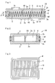
- a filter 1A according to a first embodiment includes, as shown in FIGS. 1 and 2, an upper case member 2 (which is an example of a "first case member” according to the present invention) and a lower case member 3 (which is an example of a “second case member” according to the present invention) which are rectangular dish-shaped and joined together to form a filter chamber S.
- the filter 1 also includes a filter element 4 held between the case members 2 and 3.
- An inflow port 7a for contaminated oil is formed in the lower case member 3, and an outflow port 7b is formed in the upper case member 2 for filtered oil.
- the upper case member 2 is made of a synthetic resin material having laser absorbency.
- the lower case member 3 is made of a synthetic resin material having laser absorbency.
- the case members 2 and 3 are provided with frame-shaped joining ends 2b and 3b that rise from the periphery of the bottom walls 2a and 3a, respectively. As shown in FIG. 4, the tips of the joining ends 2b and 3b are provided with convex portions 8 and 9, respectively, protruding in a joining direction P. Inner peripheral surfaces of the convex portions 8 and 9 are formed with tapered faces 8a and 9a angled in the joining direction P.
- the filter element 4 is formed by insert-molding for integrating the synthetic resin holding frame 6 having laser permeability with the periphery of a corrugated filtering medium 5 made from a non-woven fabric, as shown in FIGS. 1 to 3.
- a reinforcing rib 10 that extends in a direction orthogonal to a ridgeline of the corrugation of the filtering medium 5 (i.e. a corrugation direction) and is integrated with a center portion of the ridgeline of the corrugation of the filtering medium 5 is provided between the opposing sides of the holding frame 6.
- an upper surface and a lower surface of the holding frame 6 are provided with, as shown in FIG. 4, upper and lower concave portions 11 and 12 that engage with the convex portions 8 and 9, respectively.
- Inner peripheral surfaces of the concave portions 11 and 12 are formed with tapered faces 11a and 12a angled in the joining direction P. Furthermore, the convex portions 8 and 9 and the concave portions 11 and 12 are mutually engaged with each other with a space secured between the tip faces of the convex portions 8 and 9 and the bottom faces of the concave portions 11 and 12.
- the outer side surface (which is an example of a "contact area” according to the present invention) of the engagement portion between the convex portion 8 and the concave portion 11 is provided with a first weld portion w1 that joins the upper case member 2 and the holding frame 6 of the filter element 4. Further, the outer side surface (which is an example of the "contact area” according to the present invention) of the engagement portion between the convex portion 9 and the concave portion 12 is provided with a second weld portion w2 that joins the lower case member 3 and the holding frame 6 of the filter element 4.
- the first and second weld portions w1 and w2 are formed at the same time by laser light radiated from the side of the filter 1A (a direction orthogonal to the joining direction).
- laser light radiated toward a laser light irradiation range a1 penetrates through the holding frame 6 and reaches the outer side surfaces of the convex portions 8 and 9 of the case members 2 and 3 which are then melted. Heat generated at the melted portions is transmitted to the holding frame 6 which is then melted, forming the first and second weld portions w1 and w2 as a result. Furthermore, the aforementioned laser light irradiation is performed in a continuous and uniform manner along the outer periphery of the filter 1A while pressure is applied to the case members 2 and 3 in the joining direction P. Accordingly, the first and second weld portions w1 and w2 are formed continuously along the outer periphery of the filter 1A.
- the first and second weld portions w1 and w2 formed by laser light is provided at the contact area between the respective case members 2 and 3 and the holding frame 6 of the filter element 4. Accordingly, the first and second weld portions w1 and w2 solidly integrates three portions, that is, the case members 2 and 3 and the filter element 4. Also, compared to a weld portion formed by conventional vibration welding, the first and second weld portions w1 and w2 forming by aforementioned laser light welding can be minimized size in the direction orthogonal to the joining direction P. Moreover, use of laser welding makes it possible to suppress occurrence of welding burrs, thereby eliminating a need for a burr gutter. In consequence, a compact structure can be achieved for the filter overall.
- the convex portions 8 and 9 are provided on the case members 2 and 3, respectively, and the concave portions 11 and 12 are provided on the holding frame 6 of the filter element 4. Accordingly, engagement of the convex portion 8 and 9 with the concave portions 11 and 12 suppresses warpage of the joining portion caused by thermal expansion or the like during laser welding, thus achieving a sufficient bond strength required.
- the first and second weld portions w1 and w2 are provided at the outer side surface (opposing the filter chamber) of the respective engagement portions between the convex portions 8 and 9 and the concave portions 11 and 12, the first and second weld portions w1 and w2 can be sufficiently disposed away from the filter chamber S. Therefore, even if the welding burrs occur near the first and second weld portions w1 and w2, the burrs can be prevented from entering the filter chamber S, which in consequence prevents degradation of the product performance of the filter.
- tapered faces 8a, 9a, 11a, and 12a are provided on the inner side surfaces of the respective engagement portions between the convex portions 8 and 9 and the concave portions 11 and 12. Accordingly, a mechanical joining force produced by the tapered faces 8a, 9a, 11a, and 12a can more securely suppress warpage of the joining portions caused by thermal expansion or the like during laser welding. Further, the tapered faces 8a, 9a, 11a, and 12a absorb variances in the dimensional accuracy of the case members 2 and 3 and the holding frame 6 of the filter element 4, thereby enabling each member to be positioned more precisely.
- the configuration in which the tapered faces 8a, 9a, 11a, and 12a are provided on the inner side surfaces of the respective engagement portions between the convex portions 8 and 9 and the concave portions 11 and 12 can make a longer engagement dimension than a configuration in which a faces extending in parallel with the joining direction P are provided on the inner side surfaces of the respective engagement portions between the convex portions 8 and 9 and the concave portions 11 and 12. Consequently, the welding burrs that occur near the weld portions w1 and w2 can be more reliably suppressed from entering the filter chamber S.
- the first and second weld portions w1 and w2 are formed at the same time by single laser light radiated from the side of the filter 1A.
- the first and second weld portions w1 and w2 can be formed more easily without changing a focal point of the laser light.
- the filter element 4 including the corrugated filtering medium 5 and the holding frame 6 is held between the case members 2 and 3. Consequently, ease of assembling the filtering medium to each case member can be improved compared to a configuration in which the corrugated filtering medium is directly held between the respective case members.
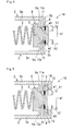
- a filter 1B according to a second embodiment includes, as shown in FIG. 5, the upper case member 2, the lower case member 3, and the filter element 4 held between the upper and lower case members 2 and 3. Note that, in the second embodiment, the same reference numerals/symbols are assigned for structural parts substantially identical to those in the first embodiment, and accompanying descriptions therefor are omitted while major differences from the first embodiment will be described.
- an engaged portion 14 that is recessed in the joining direction P is provided. Furthermore, at the outer side of the concave portions 11 and 12 of the holding frame 6 of the filter element 4, an engaging portion 15 that protrudes in the joining direction P and engages with the engaged portion 14 is provided.
- the equivalent operation and effects as in the first embodiment can be achieved, and warpage of the joining portion during laser welding can be suppressed more reliably by the engagement between the engaging portion 15 and the engaged portion 14 as well as the engagement between the convex portions 8 and 9 and the concave portions 11 and 12.
- a filter 1C according to a third embodiment includes, as shown in FIG. 6, the upper case member 2, the lower case member 3, and the filter element 4 held between the upper and lower case members 2 and 3. Note that, in the third embodiment, the same reference numerals/symbols are assigned for structural parts substantially identical to those in the first embodiment, and accompanying descriptions therefor are omitted while major differences from the first embodiment will be described.
- the upper case member 2 is made of a synthetic resin material having laser permeability.
- the lower case member 3 is made of a synthetic resin material having laser permeability.
- Respective tips of the joining ends 2b and 3b of the case members 2 and 3 are provided with the concave portions 17 and 18 that are recessed in the joining direction P.
- the inner peripheral surfaces of the concave portions 17 and 18 are provided with tapered faces 17a and 18a angled in the joining direction P.
- the holding frame 6 of the filter element 4 is made of a synthetic resin material having laser absorbency.
- the upper face and the lower face of the holding frame 6 are provided with the convex portions 19 and 20 that engage with the concave portions 17 and 18, respectively.
- the inner peripheral surfaces of the respective convex portions 19 and 20 are provided with tapered faces 19a and 20a angled in the joining direction P. Furthermore, the convex portions 19 and 20 and the concave portions 17 and 18 are engaged with each other, with a space secured between the tip faces of the convex portions 19 and 20 and the bottom faces of the concave portions 17 and 18.
- the first weld portion w1 that joins the upper case member 2 and the holding frame 6 of the filter element 4 is formed at the outer side surface (which is an example of the "contact area” according to the present invention) of the engagement portion between the convex portion 19 and the concave portion 17. Furthermore, the second weld portion w2 that joins the lower case member 3 and the holding frame 6 of the filter element 4 is formed at the outer side surface (which is an example of the "contact area” according to the present invention) of the engagement portion between the convex portion 20 and the concave portion 18.
- the first and second weld portions w1 and w2 are formed at the same time (or sequentially) by laser light radiated from the side of the filter 1C (a direction orthogonal to the joining direction).
- laser light radiated toward respective laser light irradiation ranges c1 and c2 penetrates through the case members 2 and 3 and reaches the outer side surfaces of the convex portions 19 and 20 of the holding frame 6 which are then melted. Heat generated at the melted portions is transmitted to the case members 2 and 3 which are then melted, forming the first and second weld portions w1 and w2 as a result.
- a filter 1D according to a fourth embodiment includes, as shown in FIG. 7, the upper case member 2, the lower case member 3, and the filter element 4 held between the upper and lower case members 2 and 3. Note that, in the fourth embodiment, the same reference numerals/symbols are assigned for structural parts substantially identical to those in the first embodiment, and accompanying descriptions therefor are omitted while major differences from the first embodiment will be described.
- the phase of the direction orthogonal to the joining direction P is slightly offset for the respective joining ends 2b and 3b of the case members 2 and 3.
- the respective tips of the joining ends 2b and 3b are provided with the convex portions 22 and 23 protruding in the joining direction P.
- the inner peripheral surface of the convex portion 22 is provided with a tapered face 22a angled in the joining direction P.
- the outer peripheral surface of the convex portion 23 is provided with a tapered face 23a angled in the joining direction P.
- the upper face and the lower face of the holding frame 6 of the filter element 4 are provided with the concave portions 24 and 25 that engage with the convex portions 22 and 23, respectively.
- the inner peripheral surface of the upper-side concave portion 24 is provided with a tapered face 24a angled in the joining direction P.
- the outer peripheral surface of the lower-side concave portion 25 is provided with a tapered face 25a angled in the joining direction P.
- the first weld portion w1 that joins the upper case member 2 and the holding frame 6 of the filter element 4 is formed at the outer side surface (which is an example of the "contact area” according to the present invention) of the engagement portion between the convex portion 22 and the concave portion 24.
- the second weld portion w2 that joins the lower case member 3 and the holding frame 6 of the filter element 4 is formed at the outer side surface (which is an example of the "contact area” according to the present invention) of the engagement portion between the convex portion 23 and the concave portion 25.
- the first and second weld portions w1 and w2 are formed at the same time by laser light radiated from the side of the filter 1D (a direction orthogonal to the joining direction).
- the filter 1D in the fourth embodiment the equivalent operation and effects as in the first embodiment can be obtained. Furthermore, since respective phases of the joining ends 2b and 3b of the case members 2 and 3 are offset in the direction orthogonal to the joining direction P, the first and second weld portions w1 and w2 can be disposed close to the joining direction P. Due to this configuration, laser light with a relatively narrow laser light irradiation range a1, that is, laser light of a small output can be employed.
- a filter 1E according to a fifth embodiment includes, as shown in FIG. 8, the upper case member 2, the lower case member 3, and the filter element 4 held between the upper and lower case members 2 and 3. Note that, in the fifth embodiment, the same reference numerals/symbols are assigned for structural parts substantially identical to those in the first embodiment, and accompanying descriptions therefor are omitted while major differences from the first embodiment will be described.
- the upper case member 2 is made of a synthetic resin material having laser permeability. Furthermore, the lower case member 3 is made of a synthetic resin material having laser absorbency.
- the tip of the joining end 2b of the upper case member 2 is provided with a concave portion 27 recessed in the joining direction P.
- the tip of the joining end 3b of the lower case member 3 is provided with a convex portion 28 protruded in the joining direction P.
- the inner peripheral surfaces of the concave portion 27 and the convex portion 28 are formed with tapered faces 27a and 28a angled in the joining direction P.
- the aforementioned filter element 4 is formed by holding a peripheral portion of the filtering medium 5 by the upper and lower holding frames 6a and 6b.
- the holding frame 6a is made of a synthetic resin material having laser absorbency
- the holding frame 6b is made of a synthetic resin material having laser permeability.
- the holding frames 6a and 6b are mutually fixed by adhesive bonding, welding, screwing, or the like.
- An upper face of the holding frame 6a is provided with a convex portion 29 that engages with the concave portion 27.
- a lower face of the holding frame 6b is provided with a concave portion 30 that engages with the convex portion 28. Tapered faces 29a and 30a angled in the joining direction P are formed on the inner peripheral surfaces of the convex portion 29 and the concave portion 30.
- the first weld portion w1 that joins the upper case member 2 and the holding frame 6a of the filter element 4 is formed at the outer side surface (which is an example of the "contact area” according to the present invention) of the engagement portion between the concave portion 27 and the convex portion 29.
- the second weld portion w2 that joins the lower case member 3 and the holding frame 6b of the filter element 4 is formed at the outer side surface (which is an example of the "contact area” according to the present invention) of the engagement portion between the convex portion 28 and the concave portion 30.
- the first and second weld portions w1 and w2 are formed at the same time by laser light radiated from the side of the filter 1E (a direction orthogonal to the joining direction).
- a laser light absorbing range b1 laser light radiated toward a laser light irradiation range a1 penetrates through the upper case member 2 and reaches the outer side surface of the convex portion 29 of the holding frame 6a which is then melted. Heat generated at the melted portion is transmitted to the upper case member 2 which is then melted, forming the first weld portion w1 as a result. Furthermore, in a laser light absorbing range b2, laser light radiated toward the laser light irradiation range a1 penetrates through the holding frame 6b and reaches the outer side surface of the convex portion 28 of the lower case member 3 which is then melted. Heat generated at the melted portion is transmitted to the holding frame 6b which is then melted, forming the second weld portion w2 as a result.
- the filter 1E in the fifth embodiment an operation and effects substantially identical to those in the first embodiment can be achieved. Furthermore, the engagement between the concave portion 27 of the upper case member 2 and the convex portion 29 of the holding frame 6a as well as the engagement between the convex portion 28 of the lower case member 3 and the concave portion 30 of the holding frame 6b suppress warpage of the joining portion during laser welding, thus achieving a sufficient bond strength required.
- a filter 1F according to a sixth embodiment includes, as shown in FIG. 9, the upper case member 2, the lower case member 3, and the filter element 4 held between the upper and lower case members 2 and 3. Note that, in the sixth embodiment, the same reference numerals/symbols are assigned for structural parts substantially identical to those in the first embodiment, and accompanying descriptions therefor are omitted while major differences from the first embodiment will be described.
- the upper case member 2 is made of a synthetic resin material having laser permeability. Furthermore, the lower case member 3 is made of a synthetic resin material having laser absorbency. At the outer side of the convex portion 8 of the upper case member 2, an outer wall 33 that extends in the joining direction P and a tip of which contacts the outer side surface of the base of the joining end 3b of the lower case member 3 is provided.
- the first weld portion w1 which joins the upper case member 2 and the lower case member 3 is formed at a contact area extending in the joining direction P between the tip of the outer wall 33 of the upper case member 2 and the base of the joining end 3b of the lower case member 3.
- the second weld portion w2 which joins the lower case member 3 and the holding frame 6 of the filter element 4 is provided at the outer side surface (which is an example of the "contact area" according to the present invention) of the engagement portion between the convex portion 9 of the lower case member 3 and the concave portion 12 of the holding frame 6.
- the first and second weld portions w1 and w2 are formed at the same time by laser light radiated from the side of the filter 1F (a direction orthogonal to the joining direction).
- laser light radiated toward the laser light irradiation range a1 penetrates through the outer wall 33 and reaches the outer side surface of the base of the joining end 3b of the lower case member 3 which is then melted. Heat generated at the melted portion is transmitted to the outer wall 33 which is then melted, forming the first weld portion w1 as a result.
- laser light radiated toward the laser light irradiation range a1 penetrates through the outer wall 33 and the holding frame 6 and reaches the outer side surface of the convex portion 9 of the lower case member 3 which is then melted. Heat generated at the melted portion is transmitted to the holding frame 6 which is then melted, forming the second weld portion w2 as a result.
- the filter 1F in the sixth embodiment the equivalent operation and effects as in the first embodiment can be obtained. Since the first weld portion w1 is provided between the upper case member 2 and the lower case member 3, and the second weld portion w2 is provided between the lower case member 3 and the holding frame 6, the first weld portion w1 and the second weld portion w2 can be disposed close to the joining direction P. Accordingly, due to this configuration, laser light with a relatively narrow laser light irradiation range, that is, laser light of a small output can be employed. Moreover, the outer side surface of the holding frame 6 can be covered by the outer wall 33, thereby improving the appearance of the product.
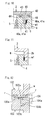
- the present invention is not limited to the first to sixth embodiments described above, and various modified embodiments are possible that fall within the scope of the present invention depending on the purpose and application. More specifically, according to the filters 1A to 1F in the aforementioned first to sixth embodiments, the tapered face is provided only on the inner side surface of the engagement portion between the convex portion, provided on one of the holding frame 6 of the filter element and the case member 2 or 3, and the concave portion provided on the other.
- the present invention is not limited by this, and, as shown in FIG. 10, tapered faces 40a and 41a can be provided on the inner side surface and the outer side surface of an engagement portion between a convex portion 40 and a concave portion 41.
- the tapered faces may be provided only on the outer side surface of the engagement portion.
- the engaging portion 15 and the engaged portion 14 are provided only at the outer side (a side opposite the filter chamber side) of the weld portions w1 and w2.
- the present invention is not limited by this, and as shown in FIG. 10, for instance, an engaging portion 43 and an engaged portion 44 can be provided on the outer side (a side opposite the filter chamber side) and the inner side (filter chamber side) of the weld portions w1 and w2.
- the engaging portion and the engaged portion may be provided only at the inner side (filter chamber side) of the weld portions.
- the convex portion provided on one of the holding frame 6 of the filter element 4 and the one case member 2 or 3 is engaged with the concave portion provided on the other.
- the present invention is not limited by this, and as shown in FIG. 11, for example, the weld portions w1 and w2 can be formed at a contact area extending in the joining direction P between the respective case members 2 and 3 and the holding frame 6 of the filter element 4 without engaging them.
- the respective case members 2 and 3 in the first to sixth embodiments can be provided with a supporting piece 46 (shown by an imaginary line in FIG. 1) for preventing collapse of the corrugated portion of the corrugated filtering medium 5.
- the filtering medium 5 is disposed in the filter chamber S of the filters 1A to 1F.
- the laser permeability can be reduced if a sufficient distance is kept between the holding frame 6 and the filtering medium 5.
- the laser light according to the first to sixth embodiments can be a semiconductor, gas, solid, liquid laser light, and the like.
- the present invention is used as a filter that filtrates contaminated fluid such as oil, fuel, and air, and more specifically, the filter is more suitably used as an oil filter for an automatic transmission of a vehicle.
- the present filter 1A comprises a first case member(an upper case member) 2 and a second case member (a lower case member) 3 that are made of synthetic resin and are mutually joined to form a filter chamber S, and a filter element 4 including a filtering medium 5 and a holding frame 6 that is made of synthetic resin, holds a peripheral portion of the filtering medium 5 and is held between joining ends 2b and 3b of the case members 2 and 3, and weld portions w1 and w2 formed by laser light are provided at a contact area extending in a joining direction P between the holding frame 6 of the filter element 4 and at least one joining end of the joining ends 2b and 3b of the case members 2 and 3.
Landscapes
- Engineering & Computer Science (AREA)
- Mechanical Engineering (AREA)
- Chemical & Material Sciences (AREA)
- Chemical Kinetics & Catalysis (AREA)
- Physics & Mathematics (AREA)
- Optics & Photonics (AREA)
- Health & Medical Sciences (AREA)
- Electromagnetism (AREA)
- Toxicology (AREA)
- Lining Or Joining Of Plastics Or The Like (AREA)
- Filtering Materials (AREA)
- Filtering Of Dispersed Particles In Gases (AREA)
Abstract
Description
- The present invention relates to a filter and a manufacturing method therefor. More specifically, the present invention relates to a filter for which a compact structure can be achieved by suppressing occurrence of welding burrs and keeping a weld portion and a burr gutter to the minimum required, and a manufacturing method therefor.
- A filter is known in which a pair of case members made of synthetic resin are welded together by vibration welding, and a filter element is held between the pair of case members (see
JP-UM-A-H05-29735
JP-UM-A-H05-29735 portion 102a is formed at a lower end rim of anupper case 102, and joiningportions portion 102a of theupper case 102 are formed respectively at an upper end rim of alower case 103 and an outer rim of ascreen frame 104. - According to
JP-UM-A-H05-29735 portion 102a of theupper case 102 is vibration-welded to both the joiningportion 103a of thelower case 103 and the joiningportion 104a of thescreen frame 104 at the same time. Accordingly, this requires a sufficient flat area to be secured on a contact area of the joiningportion 102a of theupper case 102, and a space (burr gutter) r for welding burrs that occur in a relatively large amount during vibration welding to be provided at both sides of the joiningportion 102a of theupper case 102. Furthermore, the space r and a weld portion w are normally disposed along the entire periphery of the filter, thus enlarging the size of the filter. - In light of the circumstances described above, it is an object of the present invention to provide a filter for which a compact structure can be achieved by suppressing occurrence of welding burrs and keeping a weld portion and a burr gutter to the minimum required, and a manufacturing method therefor.
- The present invention is described as follows.
- 1. A filter comprising:
- a first case member and a second case member that are made of a synthetic resin and are mutually joined to form a filter chamber; and
- a filter element including a filtering medium and a holding frame that is made of a synthetic resin, holds a peripheral portion of said filtering medium and is held between a joining end of said first case member and a joining end of said second case member,
- 2. The filter according to claim 1,
wherein one of said joining end of said one case member and said holding frame of said filter element is provided with a convex portion that protrudes in the joining direction, while the other is provided with a concave portion that engages with said convex portion, and
said weld portion is provided at an outer side surface of an engagement portion between said convex portion and said concave portion. - 3. The filter according to
claim 2,
wherein a tapered face is provided on an inner side surface of said engagement portion between said convex portion and said concave portion. - 4. The filter according to
claim
wherein, on at least one of an inner periphery side and an outer periphery side of said convex portion and said concave portion, one of said joining end of said one case member and said holding frame of said filter element is provided with an engaging portion that protrudes in the joining direction, while the other is provided with an engaged portion that engages with said engaging portion. - 5. The filter according to claim 1,
wherein a first weld portion formed by laser light is provided at a contact area extending in the joining direction between said joining end of said first case member and said holding frame of said filter element, and
wherein a second weld portion formed by laser light is provided at a contact area extending in the joining direction between said joining end of said second case member and said holding frame of said filter element. - 6. The filter according to
claim 5,
wherein said first case member and said second case member are made of a synthetic resin material having laser permeability, and said holding frame of said filter element is made of a synthetic resin material having laser absorbency, and
said first weld portion and said second weld portion are formed by laser light radiated in a direction from exposed outer side surfaces of said first case member and said second case member toward said contact area. - 7. The filter according to
claim 5,
wherein said first case member and said second case member are made of a synthetic resin material having laser absorbency, and said holding frame of said filter element is made of a synthetic resin material having laser permeability, and
said first weld portion and said second weld portion are formed by laser light radiated in a direction from exposed outer side surfaces of said holding frame of said filter element toward said contact area. - 8. The filter according to
claim 5,
wherein said holding frame of said filter element comprises an upper holding frame made of a synthetic resin material having laser absorbency and a lower holding frame made of a synthetic resin material having laser permeability, and said first case member is made of a synthetic resin material having laser permeability, and said second case member is made of a synthetic resin material having laser absorbency, and
said first weld portion and said second weld portion are formed by laser light radiated in a direction from exposed outer side surfaces of said first case member said lower holding frame of said filter element toward said contact area. - 9. The filter according to claim 1,
wherein said first case member is made of a synthetic resin material having laser permeability, and said second case member and said holding frame of said filter element are made of a synthetic resin material having laser absorbency, and an outer wall that extends in the joining direction and a tip of which contacts said outer side surface of a base of a joining end of said second case member is provided at said outer side of said convex portion of said first case member, and
wherein a first weld portion formed by laser light is provided at a contact area extending in the joining direction between said tip of said outer wall of said first case member and said base of said joining end of said second case member , and
wherein a second weld portion formed by laser light is provided at a contact area extending in the joining direction between said joining end of said second case member and said holding frame of said filter element. - 10. A manufacturing method for said filter according to any one of claims 1 to 9 , characterized in comprising said steps of:
- holding said holding frame of said filter element between said joining end of said first case member and said joining end of said second case member; and
- forming said weld portion by radiating laser light toward a contact area extending in the joining direction between said holding frame of said filter element and at least one joining end of said joining end of said first case member and said joining end of said second case member.
- The present invention is described as follows.
According to the filter of the present invention, a weld portion formed by laser light is provided at a contact area extending in a joining direction between a joining end of one of the case members and a holding frame of a filter element. Therefore, the case member and the filter element are solidly integrated by the weld portion. Furthermore, a size of the weld portion can be minimized in a direction orthogonal to the joining direction, and the use of the laser welding suppresses occurrence of welding burrs, thereby minimizing (or even omitting) a burr gutter. As a result, a compact structure can be achieved for the filter overall.
In a case in which one of the one case member and the filter element has a convex portion while the other has a concave portion and when the weld portion is provided at an outer side surface of an engagement portion between the convex and concave portions, the engagement of the convex and concave portions suppresses warpage of the joining portion from occurring during laser welding, thus achieving a sufficient bond strength required. Additionally, the weld portion can be sufficiently disposed away from a filter chamber, and even if the welding burrs occur near the weld portion, intrusion of such burrs into the filter chamber can be suppressed. Consequently, degradation of the product performance of the filter can be prevented.
Further, if a tapered face is provided on an inner side surface of the engagement portion between the convex portion and the concave portion, warpage of the joining portion during laser welding can be prevented more reliably by a mechanical joining force produced by the tapered face. In addition, the tapered face absorbs variances in a dimensional accuracy of the one case member and the holding frame of the filter element, thereby enabling more precise positioning of both members. Moreover, the tapered face allows a longer engagement dimension of the engagement portion between the convex and concave portions on the inner side surface thereof, thus more reliably suppressing the welding burrs that occur near the weld portions from entering the filter chamber.
Furthermore, in a case in which an engaging portion is provided on one of the one case member or the filter element and an engaged portion is provided on the other, warpage of the joining portion during laser welding can be suppressed more reliably by, in addition to the engagement of the convex and concave portions, the engagement of the engaging portion and the engaged portion.
Moreover, in a case in which a first weld portion formed by laser light is provided at a contact area between the first case member and the filter element and a second weld portion formed by laser light is provided at a contact area between the second case member and the filter element, the first case member, the second case member, and the filter element are solidly integrated by the weld portions. - According to a manufacturing method for the filter of the present invention, a weld portion formed by laser light is provided at a contact area extending in the joining direction between the joining end of the one case member and the holding frame of the filter element. Therefore, the one case member and the filter element are solidly integrated by the weld portion. Furthermore, the size of the weld portion in a direction orthogonal to the joining direction can be minimized, and occurrence of welding burrs can be suppressed by the use of laser welding, thus enabling minimization (or even omission) of a burr gutter. Consequently, the size of the overall filter can be minimized.
-
- FIG. 1 is a longitudinal sectional view of a filter according to a first embodiment;
- FIG. 2 is a sectional view taken along the line II-II in FIG.1;
- FIG. 3 is a plan view of a filter element;
- FIG. 4 is an enlarged view of a main portion in FIG. 1;
- FIG. 5 is a longitudinal sectional view of the filter according to a second embodiment;
- FIG. 6 is a longitudinal sectional view of the filter according to a third embodiment;
- FIG. 7 is a longitudinal sectional view of the filter according to a fourth embodiment;
- FIG. 8 is a longitudinal sectional view of the filter according to a fifth embodiment;
- FIG. 9 is a longitudinal sectional view of the filter according to a sixth embodiment;
- FIG. 10 is a sectional view of a main portion illustrating another form of joining a case member and a holding frame;
- FIG. 11 is a sectional view of a main portion illustrating yet another form of joining the case member and the holding frame; and
- FIG. 12 is a sectional view of a main portion illustrating a form of joining the cases by vibration welding according to a related art.
- 1A~1F; filter, 2; upper case member, 2b; joining end, 3; lower case member, 3b; joining end, 4; filter element, 5; filtering medium, 6; holding frame, 8,9; convex portions, 8a,9a; tapered faces, 11,12; concave portions, 11a,12a; tapered faces, 14; engaged portion, 15; engaging portion, P; joining direction, S; filter chamber, w1; first weld portion, w2; second weld portion.
- A filter according to the present invention is provided with a first case member, a second case member, and a filter element.
- The "first case member" and the "second case member" are mutually joined together to form a filter chamber, and are not particularly limited in terms of shape, size, material or the like, provided that they are made of synthetic resin. It should be noted that the state of "mutually joined together" includes a state that the case members are mutually joined together with an after-mentioned holding frame.
Conceivable shapes of the aforementioned case members include an open-ended box shape, dish shape, bowl shape, flat shape and the like.
The case members are made from materials such as a synthetic resin material having laser permeability or laser absorbency. - The "filter element" is not particularly limited in terms of shape, size, material or the like, provided that it includes a filtering medium and a synthetic resin-made holding frame that holds the peripheral portion of the filtering medium and is held between respective joining ends of the aforementioned case members.
Conceivable shapes of the filtering medium include a corrugated shape, sheet shape, wave shape and the like. In addition, materials such as non-woven fabric, woven fabric, paper and the like can conceivably be used for the filtering medium.
Examples of materials of the holding frame include a synthetic resin material having laser permeability or laser absorbency. - Examples of the synthetic resin materials composing the holding frame and the respective case members include amorphous resin such as polystyrene (PS), low-density polyethylene (LDPE), and polycarbonate (PC), and crystalline resin such as polypropylene (PP), polybutylene terephthalate (PBT), polyethylene terephthalate (PET), polyamide (PA), and polyacetal (POM).
- The filter according to the present invention includes a weld portion formed by laser light at a contact area extending in a joining direction between at least one of joining ends of the first and the second case members and the holding frame of the filter element. It should be noted that "extending in the joining direction" can also entail a state of extending at an angle to the joining direction as well as a state of extending in parallel with the joining direction.
The weld portion can be, for instance, formed by radiating laser light from the side of the filter toward the contact area. - Note that a form of joining one of the case members and the holding frame can be, for example, that one of the joining end of the one case member and the holding frame of the filter element is provided with a convex portion protruding in the joining direction, while the other is provided with a concave portion that engages with the convex portion. In this case, the weld portion can be provided at the outer side surface of the engagement portion between the convex and concave portions.
- According to the aforementioned joining form, an inner side surface of the engagement portion between the convex and concave portions can be provided with a tapered face for example.
Furthermore, the convex portion can be engaged with the concave portion with a space secured between a tip face of the convex portion and a bottom face of the concave portion. This configuration enables to more securely absorb variances in a dimensional accuracy of the first case member and the filter element.
In addition to the convex and concave portions as described above, an engaging portion protruding in the joining direction can be provided on one of the joining end of the one case member and the holding frame of the filter element, while an engaged portion that engages with the engaging portion can be provided on the other. The engaging portion and the engaged portion may be formed continuously on the entire periphery of each case member, or formed at predetermined intervals along the entire periphery of each case member. - Conceivable configurations of the filter according to the present invention are described below.
- (1) A first weld portion formed by laser light is provided at a contact area extending in the joining direction between the joining end of the first case member and the holding frame of the filter element. A second weld portion formed by laser light is provided at a contact area extending in the joining direction between the joining end of the second case member and the holding frame of the filter element.
- (2) A first weld portion formed by laser light is provided at a contact area extending in the joining direction between the joining end of the first case member and the holding frame of the filter element. A second weld portion formed by laser light is provided at a contact area extending in a joining direction between the joining end of the second case member and the joining end of the first case member.
- In the configuration (1), the aforementioned joining form is applicable, for example, between the first case member and the holding frame as well as between the second case member and the holding frame. Furthermore, in the configuration (2), the aforementioned joining form is applicable, for example, between the first case member and the holding frame.
Furthermore, the first and second weld portions according to the configurations (1) and (2) above can be formed (a) at the same time by single laser light; (b) at the same time by two laser lights; (c) in sequence by single laser light, or the like. The conformation (a) is preferable from the standpoint of forming the weld portions more easily at a lower cost.
In addition, in the configurations (1) and (2) above, the phase of the direction orthogonal to joining direction can be aligned for the first and second weld portions, and a distance from each of the first and second weld portions to the outer side surface of the filter can be set at approximately the same. Consequently, the first and second weld portions can be formed at the same time in substantially the same shape and size by single laser light without changing a focal point of the laser light or the like. - A manufacturing method for the filter according to the present invention includes the steps of holding the holding frame of the filter element between the joining end of the first case member and the joining end of the second case member, and forming the weld portion by radiating laser light toward a contact area extending in a joining direction between at least one joining end of the joining ends of the first and second case members and the holding frame of the filter element.
- In the step of holding the holding frame, the convex portion provided on one of the joining end of the one case member and the holding frame of the filter element can be engaged with the concave portion provided on the other. In the step of forming the weld portion, laser light can be radiated toward the outer side surface of the engagement portion between the convex and concave portions.
Further, in the step of holding the holding frame, in addition to the convex and concave portions, for example, the engaging portion provided on one of the joining end of the one case member and the holding frame of the filter element can be engaged with the engaged portion provided on the other.
Moreover, in the step of forming the weld portion, the first weld portion can be formed by radiating laser light toward the contact area extending in the joining direction between the joining end of the first case member and the holding frame of the filter element. In addition, the second weld portion can be formed by radiating laser light toward the contact area extending in the joining direction between the joining end of the second case member and the holding frame of the filter element - Hereinafter, a specific description of the present invention will be given based on embodiments with reference to the accompanying drawings. Note that an oil filter for an automatic transmission of a vehicle is used as an example of a filter in the embodiments.
- A
filter 1A according to a first embodiment includes, as shown in FIGS. 1 and 2, an upper case member 2 (which is an example of a "first case member" according to the present invention) and a lower case member 3 (which is an example of a "second case member" according to the present invention) which are rectangular dish-shaped and joined together to form a filter chamber S. The filter 1 also includes afilter element 4 held between thecase members inflow port 7a for contaminated oil is formed in thelower case member 3, and anoutflow port 7b is formed in theupper case member 2 for filtered oil. - The
upper case member 2 is made of a synthetic resin material having laser absorbency. Thelower case member 3 is made of a synthetic resin material having laser absorbency. Thecase members bottom walls convex portions convex portions tapered faces - The
filter element 4 is formed by insert-molding for integrating the syntheticresin holding frame 6 having laser permeability with the periphery of acorrugated filtering medium 5 made from a non-woven fabric, as shown in FIGS. 1 to 3. A reinforcingrib 10 that extends in a direction orthogonal to a ridgeline of the corrugation of the filtering medium 5 (i.e. a corrugation direction) and is integrated with a center portion of the ridgeline of the corrugation of thefiltering medium 5 is provided between the opposing sides of the holdingframe 6.
Additionally, an upper surface and a lower surface of the holdingframe 6 are provided with, as shown in FIG. 4, upper and lowerconcave portions convex portions concave portions tapered faces convex portions concave portions convex portions concave portions - The outer side surface (which is an example of a "contact area" according to the present invention) of the engagement portion between the
convex portion 8 and theconcave portion 11 is provided with a first weld portion w1 that joins theupper case member 2 and the holdingframe 6 of thefilter element 4. Further, the outer side surface (which is an example of the "contact area" according to the present invention) of the engagement portion between theconvex portion 9 and theconcave portion 12 is provided with a second weld portion w2 that joins thelower case member 3 and the holdingframe 6 of thefilter element 4. The first and second weld portions w1 and w2 are formed at the same time by laser light radiated from the side of thefilter 1A (a direction orthogonal to the joining direction). That is, in laser light absorbing ranges b1 and b2, laser light radiated toward a laser light irradiation range a1 penetrates through the holdingframe 6 and reaches the outer side surfaces of theconvex portions case members frame 6 which is then melted, forming the first and second weld portions w1 and w2 as a result.
Furthermore, the aforementioned laser light irradiation is performed in a continuous and uniform manner along the outer periphery of thefilter 1A while pressure is applied to thecase members filter 1A. - Next, operation of the
filter 1A mentioned above will be described.
Automatic transmission oil is introduced into a dusty side of the filter chamber S of thefilter 1A from theinflow port 7a, and then passes through thefiltering medium 5, reaching a clean side of the filter chamber S. As the oil passes through thefiltering medium 5, any foreign matters included in the oil can be removed by thefiltering medium 5. The oil from which the foreign matters and impurities are removed flows out of thefilter 1A from the clean side of the filter chamber S via theoutflow port 7b. - As described above, according to the
filter 1A in the first embodiment, the first and second weld portions w1 and w2 formed by laser light is provided at the contact area between therespective case members frame 6 of thefilter element 4. Accordingly, the first and second weld portions w1 and w2 solidly integrates three portions, that is, thecase members filter element 4. Also, compared to a weld portion formed by conventional vibration welding, the first and second weld portions w1 and w2 forming by aforementioned laser light welding can be minimized size in the direction orthogonal to the joining direction P. Moreover, use of laser welding makes it possible to suppress occurrence of welding burrs, thereby eliminating a need for a burr gutter. In consequence, a compact structure can be achieved for the filter overall. - Furthermore, according to the
filter 1A in the first embodiment, theconvex portions case members concave portions frame 6 of thefilter element 4. Accordingly, engagement of theconvex portion concave portions convex portions concave portions - Moreover, according to the
filter 1A in the first embodiment, tapered faces 8a, 9a, 11a, and 12a are provided on the inner side surfaces of the respective engagement portions between theconvex portions concave portions case members frame 6 of thefilter element 4, thereby enabling each member to be positioned more precisely. Moreover, in terms of an engagement dimension of the engagement portions, the configuration in which the tapered faces 8a, 9a, 11a, and 12a are provided on the inner side surfaces of the respective engagement portions between theconvex portions concave portions convex portions concave portions - Further, according to the
filter 1A in the first embodiment, the first and second weld portions w1 and w2 are formed at the same time by single laser light radiated from the side of thefilter 1A. As a result, the first and second weld portions w1 and w2 can be formed more easily without changing a focal point of the laser light.
Moreover, according to thefilter 1A in the first embodiment, thefilter element 4 including thecorrugated filtering medium 5 and the holdingframe 6 is held between thecase members - A
filter 1B according to a second embodiment includes, as shown in FIG. 5, theupper case member 2, thelower case member 3, and thefilter element 4 held between the upper andlower case members - At the outer side of the
convex portions case members portion 14 that is recessed in the joining direction P is provided. Furthermore, at the outer side of theconcave portions frame 6 of thefilter element 4, an engagingportion 15 that protrudes in the joining direction P and engages with the engagedportion 14 is provided. - Consequently, according to the
filter 1B in the second embodiment, the equivalent operation and effects as in the first embodiment can be achieved, and warpage of the joining portion during laser welding can be suppressed more reliably by the engagement between the engagingportion 15 and the engagedportion 14 as well as the engagement between theconvex portions concave portions - A
filter 1C according to a third embodiment includes, as shown in FIG. 6, theupper case member 2, thelower case member 3, and thefilter element 4 held between the upper andlower case members - The
upper case member 2 is made of a synthetic resin material having laser permeability. Thelower case member 3 is made of a synthetic resin material having laser permeability. Respective tips of the joining ends 2b and 3b of thecase members concave portions concave portions tapered faces - The holding
frame 6 of thefilter element 4 is made of a synthetic resin material having laser absorbency. The upper face and the lower face of the holdingframe 6 are provided with theconvex portions concave portions convex portions tapered faces convex portions concave portions convex portions concave portions - The first weld portion w1 that joins the
upper case member 2 and the holdingframe 6 of thefilter element 4 is formed at the outer side surface (which is an example of the "contact area" according to the present invention) of the engagement portion between theconvex portion 19 and theconcave portion 17. Furthermore, the second weld portion w2 that joins thelower case member 3 and the holdingframe 6 of thefilter element 4 is formed at the outer side surface (which is an example of the "contact area" according to the present invention) of the engagement portion between theconvex portion 20 and theconcave portion 18. The first and second weld portions w1 and w2 are formed at the same time (or sequentially) by laser light radiated from the side of thefilter 1C (a direction orthogonal to the joining direction). That is, laser light radiated toward respective laser light irradiation ranges c1 and c2 penetrates through thecase members convex portions frame 6 which are then melted. Heat generated at the melted portions is transmitted to thecase members - Consequently, according to the
filter 1C in the third embodiment, an operation and effects substantially identical to those in the first embodiment can be achieved, and warpage of the joining portion during laser welding can be suppressed by the engagement of theconcave portions case members convex portions frame 6 of thefilter element 4, thereby achieving a sufficient bond strength required. - A
filter 1D according to a fourth embodiment includes, as shown in FIG. 7, theupper case member 2, thelower case member 3, and thefilter element 4 held between the upper andlower case members - The phase of the direction orthogonal to the joining direction P is slightly offset for the respective joining ends 2b and 3b of the
case members convex portions convex portion 22 is provided with atapered face 22a angled in the joining direction P. Further, the outer peripheral surface of theconvex portion 23 is provided with atapered face 23a angled in the joining direction P. - The upper face and the lower face of the holding
frame 6 of thefilter element 4 are provided with theconcave portions convex portions concave portion 24 is provided with atapered face 24a angled in the joining direction P. Further, the outer peripheral surface of the lower-sideconcave portion 25 is provided with atapered face 25a angled in the joining direction P. - The first weld portion w1 that joins the
upper case member 2 and the holdingframe 6 of thefilter element 4 is formed at the outer side surface (which is an example of the "contact area" according to the present invention) of the engagement portion between theconvex portion 22 and theconcave portion 24. Additionally, the second weld portion w2 that joins thelower case member 3 and the holdingframe 6 of thefilter element 4 is formed at the outer side surface (which is an example of the "contact area" according to the present invention) of the engagement portion between theconvex portion 23 and theconcave portion 25. The first and second weld portions w1 and w2 are formed at the same time by laser light radiated from the side of thefilter 1D (a direction orthogonal to the joining direction). - Consequently, according to the
filter 1D in the fourth embodiment, the equivalent operation and effects as in the first embodiment can be obtained. Furthermore, since respective phases of the joining ends 2b and 3b of thecase members - A
filter 1E according to a fifth embodiment includes, as shown in FIG. 8, theupper case member 2, thelower case member 3, and thefilter element 4 held between the upper andlower case members - The
upper case member 2 is made of a synthetic resin material having laser permeability. Furthermore, thelower case member 3 is made of a synthetic resin material having laser absorbency. In addition, the tip of the joiningend 2b of theupper case member 2 is provided with aconcave portion 27 recessed in the joining direction P. The tip of the joiningend 3b of thelower case member 3 is provided with aconvex portion 28 protruded in the joining direction P. The inner peripheral surfaces of theconcave portion 27 and theconvex portion 28 are formed withtapered faces - The
aforementioned filter element 4 is formed by holding a peripheral portion of thefiltering medium 5 by the upper and lower holdingframes frame 6a is made of a synthetic resin material having laser absorbency, while the holdingframe 6b is made of a synthetic resin material having laser permeability. Furthermore, the holdingframes frame 6a is provided with aconvex portion 29 that engages with theconcave portion 27. Additionally, a lower face of the holdingframe 6b is provided with aconcave portion 30 that engages with theconvex portion 28. Tapered faces 29a and 30a angled in the joining direction P are formed on the inner peripheral surfaces of theconvex portion 29 and theconcave portion 30. - the first weld portion w1 that joins the
upper case member 2 and the holdingframe 6a of thefilter element 4 is formed at the outer side surface (which is an example of the "contact area" according to the present invention) of the engagement portion between theconcave portion 27 and theconvex portion 29. Further, the second weld portion w2 that joins thelower case member 3 and the holdingframe 6b of thefilter element 4 is formed at the outer side surface (which is an example of the "contact area" according to the present invention) of the engagement portion between theconvex portion 28 and theconcave portion 30. The first and second weld portions w1 and w2 are formed at the same time by laser light radiated from the side of thefilter 1E (a direction orthogonal to the joining direction). That is, in a laser light absorbing range b1, laser light radiated toward a laser light irradiation range a1 penetrates through theupper case member 2 and reaches the outer side surface of theconvex portion 29 of the holdingframe 6a which is then melted. Heat generated at the melted portion is transmitted to theupper case member 2 which is then melted, forming the first weld portion w1 as a result. Furthermore, in a laser light absorbing range b2, laser light radiated toward the laser light irradiation range a1 penetrates through the holdingframe 6b and reaches the outer side surface of theconvex portion 28 of thelower case member 3 which is then melted. Heat generated at the melted portion is transmitted to the holdingframe 6b which is then melted, forming the second weld portion w2 as a result. - Consequently, according to the
filter 1E in the fifth embodiment, an operation and effects substantially identical to those in the first embodiment can be achieved. Furthermore, the engagement between theconcave portion 27 of theupper case member 2 and theconvex portion 29 of the holdingframe 6a as well as the engagement between theconvex portion 28 of thelower case member 3 and theconcave portion 30 of the holdingframe 6b suppress warpage of the joining portion during laser welding, thus achieving a sufficient bond strength required. - A
filter 1F according to a sixth embodiment includes, as shown in FIG. 9, theupper case member 2, thelower case member 3, and thefilter element 4 held between the upper andlower case members - The
upper case member 2 is made of a synthetic resin material having laser permeability. Furthermore, thelower case member 3 is made of a synthetic resin material having laser absorbency. At the outer side of theconvex portion 8 of theupper case member 2, anouter wall 33 that extends in the joining direction P and a tip of which contacts the outer side surface of the base of the joiningend 3b of thelower case member 3 is provided. - The first weld portion w1 which joins the
upper case member 2 and thelower case member 3 is formed at a contact area extending in the joining direction P between the tip of theouter wall 33 of theupper case member 2 and the base of the joiningend 3b of thelower case member 3. The second weld portion w2 which joins thelower case member 3 and the holdingframe 6 of thefilter element 4 is provided at the outer side surface (which is an example of the "contact area" according to the present invention) of the engagement portion between theconvex portion 9 of thelower case member 3 and theconcave portion 12 of the holdingframe 6. The first and second weld portions w1 and w2 are formed at the same time by laser light radiated from the side of thefilter 1F (a direction orthogonal to the joining direction). That is, in the laser light absorbing range b1, laser light radiated toward the laser light irradiation range a1 penetrates through theouter wall 33 and reaches the outer side surface of the base of the joiningend 3b of thelower case member 3 which is then melted. Heat generated at the melted portion is transmitted to theouter wall 33 which is then melted, forming the first weld portion w1 as a result. Furthermore, in the laser light absorbing range b2, laser light radiated toward the laser light irradiation range a1 penetrates through theouter wall 33 and the holdingframe 6 and reaches the outer side surface of theconvex portion 9 of thelower case member 3 which is then melted. Heat generated at the melted portion is transmitted to the holdingframe 6 which is then melted, forming the second weld portion w2 as a result. - Consequently, according to the
filter 1F in the sixth embodiment, the equivalent operation and effects as in the first embodiment can be obtained. Since the first weld portion w1 is provided between theupper case member 2 and thelower case member 3, and the second weld portion w2 is provided between thelower case member 3 and the holdingframe 6, the first weld portion w1 and the second weld portion w2 can be disposed close to the joining direction P. Accordingly, due to this configuration, laser light with a relatively narrow laser light irradiation range, that is, laser light of a small output can be employed. Moreover, the outer side surface of the holdingframe 6 can be covered by theouter wall 33, thereby improving the appearance of the product. - It should be noted that the present invention is not limited to the first to sixth embodiments described above, and various modified embodiments are possible that fall within the scope of the present invention depending on the purpose and application.
More specifically, according to thefilters 1A to 1F in the aforementioned first to sixth embodiments, the tapered face is provided only on the inner side surface of the engagement portion between the convex portion, provided on one of the holdingframe 6 of the filter element and thecase member convex portion 40 and aconcave portion 41. Moreover, the tapered faces may be provided only on the outer side surface of the engagement portion.
Furthermore, in the second embodiment, the engagingportion 15 and the engagedportion 14 are provided only at the outer side (a side opposite the filter chamber side) of the weld portions w1 and w2. However, the present invention is not limited by this, and as shown in FIG. 10, for instance, an engagingportion 43 and an engagedportion 44 can be provided on the outer side (a side opposite the filter chamber side) and the inner side (filter chamber side) of the weld portions w1 and w2. Furthermore, the engaging portion and the engaged portion may be provided only at the inner side (filter chamber side) of the weld portions. - Furthermore, according to the first to sixth embodiments, the convex portion provided on one of the holding
frame 6 of thefilter element 4 and the onecase member respective case members frame 6 of thefilter element 4 without engaging them. - Additionally, the
respective case members corrugated filtering medium 5.
Moreover, according to the first to sixth embodiments, thefiltering medium 5 is disposed in the filter chamber S of thefilters 1A to 1F. However, even if the filter chamber S includes therein any other internal parts affected by laser light, the laser permeability can be reduced if a sufficient distance is kept between the holdingframe 6 and thefiltering medium 5.
Furthermore, the laser light according to the first to sixth embodiments can be a semiconductor, gas, solid, liquid laser light, and the like. - The present invention is used as a filter that filtrates contaminated fluid such as oil, fuel, and air, and more specifically, the filter is more suitably used as an oil filter for an automatic transmission of a vehicle.
Thepresent filter 1A comprises a first case member(an upper case member) 2 and a second case member (a lower case member) 3 that are made of synthetic resin and are mutually joined to form a filter chamber S, and afilter element 4 including afiltering medium 5 and a holdingframe 6 that is made of synthetic resin, holds a peripheral portion of thefiltering medium 5 and is held between joiningends case members frame 6 of thefilter element 4 and at least one joining end of the joining ends 2b and 3b of thecase members
Claims (10)
- A filter comprising:a first case member and a second case member that are made of a synthetic resin and are mutually joined to form a filter chamber; anda filter element including a filtering medium and a holding frame that is made of a synthetic resin, holds a peripheral portion of said filtering medium and is held between a joining end of said first case member and a joining end of said second case member,characterized in that a weld portion formed by laser light is provided at a contact area extending in a joining direction between said holding frame of said filter element and at least one joining end of said joining end of first case member and said joining end of second case member.
- The filter according to claim 1,
wherein one of said joining end of said one case member and said holding frame of said filter element is provided with a convex portion that protrudes in the joining direction, while the other is provided with a concave portion that engages with said convex portion, and
said weld portion is provided at an outer side surface of an engagement portion between said convex portion and said concave portion. - The filter according to claim 2,
wherein a tapered face is provided on an inner side surface of said engagement portion between said convex portion and said concave portion. - The filter according to claim 2 or 3,
wherein, on at least one of an inner periphery side and an outer periphery side of said convex portion and said concave portion, one of said joining end of said one case member and said holding frame of said filter element is provided with an engaging portion that protrudes in the joining direction, while the other is provided with an engaged portion that engages with said engaging portion. - The filter according to claim 1,
wherein a first weld portion formed by laser light is provided at a contact area extending in the joining direction between said joining end of said first case member and said holding frame of said filter element, and
wherein a second weld portion formed by laser light is provided at a contact area extending in the joining direction between said joining end of said second case member and said holding frame of said filter element. - The filter according to claim 5,
wherein said first case member and said second case member are made of a synthetic resin material having laser permeability, and said holding frame of said filter element is made of a synthetic resin material having laser absorbency, and
said first weld portion and said second weld portion are formed by laser light radiated in a direction from exposed outer side surfaces of said first case member and said second case member toward said contact area. - The filter according to claim 5,
wherein said first case member and said second case member are made of a synthetic resin material having laser absorbency, and said holding frame of said filter element is made of a synthetic resin material having laser permeability, and
said first weld portion and said second weld portion are formed by laser light radiated in a direction from exposed outer side surfaces of said holding frame of said filter element toward said contact area. - The filter according to claim 5,
wherein said holding frame of said filter element comprises an upper holding frame made of a synthetic resin material having laser absorbency and a lower holding frame made of a synthetic resin material having laser permeability, and said first case member is made of a synthetic resin material having laser permeability, and said second case member is made of a synthetic resin material having laser absorbency, and
said first weld portion and said second weld portion are formed by laser light radiated in a direction from exposed outer side surfaces of said first case member said lower holding frame of said filter element toward said contact area. - The filter according to claim 1,
wherein said first case member is made of a synthetic resin material having laser permeability, and said second case member and said holding frame of said filter element are made of a synthetic resin material having laser absorbency, and an outer wall that extends in the joining direction and a tip of which contacts said outer side surface of a base of a joining end of said second case member is provided at said outer side of said convex portion of said first case member, and
wherein a first weld portion formed by laser light is provided at a contact area extending in the joining direction between said tip of said outer wall of said first case member and said base of said joining end of said second case member , and
wherein a second weld portion formed by laser light is provided at a contact area extending in the joining direction between said joining end of said second case member and said holding frame of said filter element. - A manufacturing method for said filter according to any one of claims 1 to 9 , characterized in comprising said steps of:holding said holding frame of said filter element between said joining end of said first case member and said joining end of said second case member; andforming said weld portion by radiating laser light toward a contact area extending in the joining direction between said holding frame of said filter element and at least one joining end of said joining end of said first case member and said joining end of said second case member.
Applications Claiming Priority (1)
| Application Number | Priority Date | Filing Date | Title |
|---|---|---|---|
| JP2006247302A JP4371134B2 (en) | 2006-09-12 | 2006-09-12 | Filter and manufacturing method thereof |
Publications (2)
| Publication Number | Publication Date |
|---|---|
| EP1900410A2 true EP1900410A2 (en) | 2008-03-19 |
| EP1900410A3 EP1900410A3 (en) | 2010-03-10 |
Family
ID=38814423
Family Applications (1)
| Application Number | Title | Priority Date | Filing Date |
|---|---|---|---|
| EP07114449A Withdrawn EP1900410A3 (en) | 2006-09-12 | 2007-08-16 | Filter and manufacturing method therefor |
Country Status (4)
| Country | Link |
|---|---|
| US (1) | US8006848B2 (en) |
| EP (1) | EP1900410A3 (en) |
| JP (1) | JP4371134B2 (en) |
| CN (1) | CN101164653B (en) |
Cited By (1)
| Publication number | Priority date | Publication date | Assignee | Title |
|---|---|---|---|---|
| EP2402145A3 (en) * | 2010-06-29 | 2017-03-08 | Robert Bosch GmbH | Connection of three components by means of laser beam welding |
Families Citing this family (22)
| Publication number | Priority date | Publication date | Assignee | Title |
|---|---|---|---|---|
| JP5233695B2 (en) * | 2009-01-20 | 2013-07-10 | トヨタ紡織株式会社 | Fluid filter for automatic transmission and method for manufacturing the same |
| JP5104807B2 (en) * | 2009-04-10 | 2012-12-19 | トヨタ紡織株式会社 | Method for manufacturing fluid filter for automatic transmission |
| JP5311138B2 (en) * | 2009-09-28 | 2013-10-09 | トヨタ紡織株式会社 | Filter and manufacturing method thereof |
| JP5609237B2 (en) * | 2010-04-26 | 2014-10-22 | トヨタ紡織株式会社 | Fluid filter for automatic transmission |
| JP5691893B2 (en) * | 2011-07-04 | 2015-04-01 | トヨタ紡織株式会社 | Fluid filter |
| JP5664486B2 (en) * | 2011-07-25 | 2015-02-04 | トヨタ紡織株式会社 | Fluid filter |
| JP5862315B2 (en) * | 2012-01-12 | 2016-02-16 | トヨタ紡織株式会社 | Manufacturing method of resin molded products |
| JP5976803B2 (en) * | 2012-07-05 | 2016-08-24 | 旭化成株式会社 | Welding method and welded body |
| JP6263331B2 (en) * | 2013-02-21 | 2018-01-17 | 株式会社Roki | Filter element |
| JP6167776B2 (en) * | 2013-09-06 | 2017-07-26 | 浜名湖電装株式会社 | Three-member laser welding structure |
| DE102014004740A1 (en) * | 2014-04-01 | 2015-10-01 | Daimler Ag | Air filter for a ventilation device of a motor vehicle |
| US10388920B2 (en) * | 2014-08-26 | 2019-08-20 | Cps Technology Holdings Llc | Collar for sealing a battery module |
| CN105757934A (en) * | 2016-03-31 | 2016-07-13 | 亿丰洁净科技江苏股份有限公司 | Efficient air supply port |
| CN105757938A (en) * | 2016-03-31 | 2016-07-13 | 亿丰洁净科技江苏股份有限公司 | Efficient air supply opening with good cleaning effect |
| CN108224658B (en) * | 2017-12-20 | 2019-10-01 | 上海依瓦达环境技术有限公司 | New-air purifying system equipped with constant humidity mechanism |
| JP6611379B2 (en) * | 2018-02-07 | 2019-11-27 | 三菱重工業株式会社 | Filter device |
| CN109529483B (en) * | 2018-12-28 | 2021-04-13 | 佛山市顺德区阿波罗环保器材有限公司 | Filter element, air filtering assembly and automobile air conditioning system |
| CN212253099U (en) * | 2020-01-09 | 2020-12-29 | 盾安环境技术有限公司 | Filtering silencer and air conditioning equipment |
| JP7549291B2 (en) * | 2020-12-24 | 2024-09-11 | セイコーエプソン株式会社 | Flow path member, liquid ejection head, liquid ejection device, and method for manufacturing liquid ejection device |
| JP2025179287A (en) * | 2022-11-11 | 2025-12-10 | アルプスアルパイン株式会社 | Electronic devices and vibration generating devices |
| US11872416B1 (en) * | 2023-03-14 | 2024-01-16 | Moldex-Metric, Inc. | Filter and method |
| WO2025083778A1 (en) * | 2023-10-17 | 2025-04-24 | 株式会社ジェイテクト | Welding method, resin joint, and polygonal case |
Family Cites Families (17)
| Publication number | Priority date | Publication date | Assignee | Title |
|---|---|---|---|---|
| BE788211A (en) * | 1971-09-16 | 1973-02-28 | Pall Corp | DEVICE AVAILABLE FOR FILTERING GAS |
| FR2677883B1 (en) * | 1991-06-24 | 1997-07-18 | Maco Pharma Sa | FILTER POCKET FOR ALLOWING STERILE BLOOD FILTRATION AND BLOOD COLLECTION POCKET SET. |
| JPH0529735A (en) | 1991-07-19 | 1993-02-05 | Tatsuta Electric Wire & Cable Co Ltd | Flexible printed circuit board |
| US6131573A (en) * | 1997-03-24 | 2000-10-17 | Vickie Natale-Brown | Apparatus and method of manufacturing pulmonary function filter |
| DE19733021C2 (en) * | 1997-07-31 | 2002-05-29 | Vivascience Ag | Filtration unit made of plastic and process for its production |
| US6193833B1 (en) * | 1998-09-04 | 2001-02-27 | Spx Corporation | Method of laser welding transmission filter housing components |
| JP2001105500A (en) * | 1999-08-05 | 2001-04-17 | Toyota Motor Corp | Resin molded product and method for producing the same |
| US6568540B1 (en) * | 2000-12-13 | 2003-05-27 | Nelson Industries, Inc. | Low force closure filter with integral seal |
| DE60220733T2 (en) * | 2001-03-02 | 2007-10-18 | Filtertek, Inc., Hebron | Oil pan filter with filter cartridge |
| DE10301353A1 (en) | 2003-01-16 | 2004-07-29 | Mann + Hummel Gmbh | Filter device for filtering a fluid |
| US6890366B2 (en) * | 2003-04-17 | 2005-05-10 | Visteon Global Technologies, Inc. | Sealed engine air filter system |
| JP2005007623A (en) * | 2003-06-17 | 2005-01-13 | Aisan Ind Co Ltd | Welded structure of three members |
| JP4643187B2 (en) * | 2004-07-07 | 2011-03-02 | 日本ケンブリッジフィルター株式会社 | Bag type air filter |
| DE102004045421A1 (en) | 2004-09-18 | 2006-03-30 | Mann+Hummel Gmbh | Fluid filter for filtering liquids comprises a ball-shaped housing containing a filter element which separates a crude side from a pure side |
| JP4592446B2 (en) * | 2005-02-28 | 2010-12-01 | ダイキョーニシカワ株式会社 | Vehicle fluid filter device and method of manufacturing the same |
| US20060219624A1 (en) * | 2005-03-29 | 2006-10-05 | Toyota Boshoku Kabushiki Kaisya | Filter and manufacturing method therefor |
| JP4458025B2 (en) | 2005-11-17 | 2010-04-28 | トヨタ紡織株式会社 | Filter and manufacturing method thereof |
-
2006
- 2006-09-12 JP JP2006247302A patent/JP4371134B2/en not_active Expired - Fee Related
-
2007
- 2007-08-03 US US11/833,508 patent/US8006848B2/en not_active Expired - Fee Related
- 2007-08-16 EP EP07114449A patent/EP1900410A3/en not_active Withdrawn
- 2007-08-31 CN CN2007101483358A patent/CN101164653B/en not_active Expired - Fee Related
Non-Patent Citations (1)
| Title |
|---|
| None |
Cited By (1)
| Publication number | Priority date | Publication date | Assignee | Title |
|---|---|---|---|---|
| EP2402145A3 (en) * | 2010-06-29 | 2017-03-08 | Robert Bosch GmbH | Connection of three components by means of laser beam welding |
Also Published As
| Publication number | Publication date |
|---|---|
| US8006848B2 (en) | 2011-08-30 |
| CN101164653A (en) | 2008-04-23 |
| CN101164653B (en) | 2012-07-04 |
| EP1900410A3 (en) | 2010-03-10 |
| JP2008068169A (en) | 2008-03-27 |
| JP4371134B2 (en) | 2009-11-25 |
| US20080060987A1 (en) | 2008-03-13 |
Similar Documents
| Publication | Publication Date | Title |
|---|---|---|
| US8006848B2 (en) | Filter and manufacturing method therefor | |
| EP1710007B1 (en) | Filter and manufacturing method therefor | |
| JP4636027B2 (en) | Filter and manufacturing method thereof | |
| US7811350B2 (en) | Filter device, manufacturing method for the same, and filter element securing tool | |
| JP2015503446A (en) | Air filter element having a retaining shape | |
| JP2015509044A (en) | Air filter element having a retaining shape | |
| JP2011230039A (en) | Fluid filter for automatic transmission | |
| WO2014045545A1 (en) | Oil strainer | |
| JP2009062912A (en) | Fuel filter device and manufacturing method thereof | |
| CN1846834B (en) | Filter and its manufacturing method | |
| JP4458025B2 (en) | Filter and manufacturing method thereof | |
| JP5311138B2 (en) | Filter and manufacturing method thereof | |
| JP5212290B2 (en) | Filter manufacturing method | |
| JP4432887B2 (en) | Filter and manufacturing method thereof | |
| JP5233695B2 (en) | Fluid filter for automatic transmission and method for manufacturing the same | |
| JP2012052453A (en) | Oil strainer | |
| JP4747947B2 (en) | filter | |
| JP4839978B2 (en) | Oil filter | |
| JP6695782B2 (en) | Fuel filter | |
| JP2011112090A (en) | Fluid filter for automatic transmissions, and method of manufacturing the same | |
| CN219938443U (en) | Welding fixing structure and camera module | |
| KR19980701370A (en) | SYNTHETIC RESIN PANEL WELDING METHOD AND HOLLOW PANEL STRUCTURES FABRICATED BY THE METHOD | |
| WO2012120605A1 (en) | Filter device | |
| TW202334728A (en) | Camera and procedure for producing a camera | |
| JP5431974B2 (en) | Filter device |
Legal Events
| Date | Code | Title | Description |
|---|---|---|---|
| PUAI | Public reference made under article 153(3) epc to a published international application that has entered the european phase |
Free format text: ORIGINAL CODE: 0009012 |
|
| 17P | Request for examination filed |
Effective date: 20070816 |
|
| AK | Designated contracting states |
Kind code of ref document: A2 Designated state(s): AT BE BG CH CY CZ DE DK EE ES FI FR GB GR HU IE IS IT LI LT LU LV MC MT NL PL PT RO SE SI SK TR |
|
| AX | Request for extension of the european patent |
Extension state: AL BA HR MK YU |
|
| PUAL | Search report despatched |
Free format text: ORIGINAL CODE: 0009013 |
|
| AK | Designated contracting states |
Kind code of ref document: A3 Designated state(s): AT BE BG CH CY CZ DE DK EE ES FI FR GB GR HU IE IS IT LI LT LU LV MC MT NL PL PT RO SE SI SK TR |
|
| AX | Request for extension of the european patent |
Extension state: AL BA HR MK RS |
|
| AKX | Designation fees paid |
Designated state(s): DE FR GB |
|
| 17Q | First examination report despatched |
Effective date: 20160614 |
|
| STAA | Information on the status of an ep patent application or granted ep patent |
Free format text: STATUS: THE APPLICATION IS DEEMED TO BE WITHDRAWN |
|
| 18D | Application deemed to be withdrawn |
Effective date: 20161025 |