EP1900334B1 - Bone anchoring device - Google Patents
Bone anchoring device Download PDFInfo
- Publication number
- EP1900334B1 EP1900334B1 EP06019341A EP06019341A EP1900334B1 EP 1900334 B1 EP1900334 B1 EP 1900334B1 EP 06019341 A EP06019341 A EP 06019341A EP 06019341 A EP06019341 A EP 06019341A EP 1900334 B1 EP1900334 B1 EP 1900334B1
- Authority
- EP
- European Patent Office
- Prior art keywords
- bone anchoring
- anchoring device
- connection
- seat
- connection element
- Prior art date
- Legal status (The legal status is an assumption and is not a legal conclusion. Google has not performed a legal analysis and makes no representation as to the accuracy of the status listed.)
- Not-in-force
Links
Images


Classifications
-
- A—HUMAN NECESSITIES
- A61—MEDICAL OR VETERINARY SCIENCE; HYGIENE
- A61B—DIAGNOSIS; SURGERY; IDENTIFICATION
- A61B17/00—Surgical instruments, devices or methods, e.g. tourniquets
- A61B17/56—Surgical instruments or methods for treatment of bones or joints; Devices specially adapted therefor
- A61B17/58—Surgical instruments or methods for treatment of bones or joints; Devices specially adapted therefor for osteosynthesis, e.g. bone plates, screws, setting implements or the like
- A61B17/68—Internal fixation devices, including fasteners and spinal fixators, even if a part thereof projects from the skin
- A61B17/70—Spinal positioners or stabilisers ; Bone stabilisers comprising fluid filler in an implant
- A61B17/7001—Screws or hooks combined with longitudinal elements which do not contact vertebrae
- A61B17/7032—Screws or hooks with U-shaped head or back through which longitudinal rods pass
-
- A—HUMAN NECESSITIES
- A61—MEDICAL OR VETERINARY SCIENCE; HYGIENE
- A61B—DIAGNOSIS; SURGERY; IDENTIFICATION
- A61B17/00—Surgical instruments, devices or methods, e.g. tourniquets
- A61B17/56—Surgical instruments or methods for treatment of bones or joints; Devices specially adapted therefor
- A61B17/58—Surgical instruments or methods for treatment of bones or joints; Devices specially adapted therefor for osteosynthesis, e.g. bone plates, screws, setting implements or the like
- A61B17/68—Internal fixation devices, including fasteners and spinal fixators, even if a part thereof projects from the skin
- A61B17/70—Spinal positioners or stabilisers ; Bone stabilisers comprising fluid filler in an implant
- A61B17/7001—Screws or hooks combined with longitudinal elements which do not contact vertebrae
- A61B17/7035—Screws or hooks, wherein a rod-clamping part and a bone-anchoring part can pivot relative to each other
- A61B17/7037—Screws or hooks, wherein a rod-clamping part and a bone-anchoring part can pivot relative to each other wherein pivoting is blocked when the rod is clamped
-
- A—HUMAN NECESSITIES
- A61—MEDICAL OR VETERINARY SCIENCE; HYGIENE
- A61B—DIAGNOSIS; SURGERY; IDENTIFICATION
- A61B17/00—Surgical instruments, devices or methods, e.g. tourniquets
- A61B17/56—Surgical instruments or methods for treatment of bones or joints; Devices specially adapted therefor
- A61B17/58—Surgical instruments or methods for treatment of bones or joints; Devices specially adapted therefor for osteosynthesis, e.g. bone plates, screws, setting implements or the like
- A61B17/68—Internal fixation devices, including fasteners and spinal fixators, even if a part thereof projects from the skin
- A61B17/70—Spinal positioners or stabilisers ; Bone stabilisers comprising fluid filler in an implant
- A61B17/7001—Screws or hooks combined with longitudinal elements which do not contact vertebrae
- A61B17/7002—Longitudinal elements, e.g. rods
- A61B17/7004—Longitudinal elements, e.g. rods with a cross-section which varies along its length
- A61B17/7005—Parts of the longitudinal elements, e.g. their ends, being specially adapted to fit in the screw or hook heads
-
- A—HUMAN NECESSITIES
- A61—MEDICAL OR VETERINARY SCIENCE; HYGIENE
- A61B—DIAGNOSIS; SURGERY; IDENTIFICATION
- A61B17/00—Surgical instruments, devices or methods, e.g. tourniquets
- A61B17/56—Surgical instruments or methods for treatment of bones or joints; Devices specially adapted therefor
- A61B17/58—Surgical instruments or methods for treatment of bones or joints; Devices specially adapted therefor for osteosynthesis, e.g. bone plates, screws, setting implements or the like
- A61B17/68—Internal fixation devices, including fasteners and spinal fixators, even if a part thereof projects from the skin
- A61B17/70—Spinal positioners or stabilisers ; Bone stabilisers comprising fluid filler in an implant
- A61B17/7001—Screws or hooks combined with longitudinal elements which do not contact vertebrae
- A61B17/7002—Longitudinal elements, e.g. rods
- A61B17/7019—Longitudinal elements having flexible parts, or parts connected together, such that after implantation the elements can move relative to each other
- A61B17/7031—Longitudinal elements having flexible parts, or parts connected together, such that after implantation the elements can move relative to each other made wholly or partly of flexible material
Definitions
- the invention relates to a bone anchoring device according to the preamble of claim 1.
- Bone anchoring devices comprising a bone screw and a flexible rod which is made of an elastic material are known from EP 1 364 622 A2 and EP 1 527 742 A1 .
- the rod has a corrugated surface which cooperates with a rib structure provided on the bottom of the receiving part of the bone screw to form a form-fit connection.
- the bone anchoring device according to EP 1 527 742 A1 additionally comprises a closure element which has a rib structure engaging the corrugated surface of the rod.
- the positioning of the corrugated surfaces of the rod relative to the rib structure requires a precise insertion of the rod into the receiving part to avoid tilting. Furthermore, a continuous positioning is not possible. This makes the adjustment of the position of the rod relative to the receiving part difficult and time consuming.
- US 2004/0138660 A1 discloses a locking cap assembly for locking a rigid rod to a receiving body of a bone screw.
- the locking cap assembly includes an inner and an outer locking element.
- the outer locking element is a nut-like member and the inner locking element is rotatably connected to the outer locking element.
- the inner locking element has on its side facing the rod a ring-shaped deformable contacting element which comes into contact with the rod.
- the deformable element is deformed which provides feed-back to the surgeon to allow him to determine whether the locking cap assembly is tightened to the required extent.
- the deformable element is a deformable metallic ring which becomes cold welded to the rod.
- US-6,224,598 B1 discloses a generic bone anchoring device comprising an anchoring element comprising a shank to be anchored in a bone or a vertebra; a connection element for connecting at least two anchoring elements; a receiving part being connected to the shank for receiving the connection element and connecting the connection element to the shank; a seat for the connection element the seat being provided in the receiving part; a one piece locking element being rotatably engageable with the receiving part for fixation of the connection element in the seat; wherein at least the portion of the connection element which is received in the recess has a substantially smooth surface and wherein the locking element has an engagement structure which contacts the surface of the connection element.
- a sharp edged annular ring provides a three-point-support of the rigid and curved connection element.
- connection elements having rigid connection elements are known from EP-0 348 272 A1 ; US-6,652,526 B1 ; US2005/203518 A1 and EP-1 527 742 A1 , where the connection elements are either plastically deformed by an engagement with the locking element/receiving part (thereby, destroying the integral structure of the material of the connection element) or establish a form-fit connection by corresponding grooves and ribs.
- the bone anchoring device has the advantage that during tightening of the locking element the deformation of the elastic material of the rod leads to an indirect or dynamic force-fit connection between the elastic rod, the receiving part and the locking element without harming the integral structure of the rod.
- the rod Since the rod has a smooth surface, continuous positioning of the rod is possible.
- the bone anchoring device has furthermore the advantage that a flow of the material of the rod in a direction along the longitudinal axis of the rod is minimized.
- the fixation of the rod is achieved with a small number of parts. Therefore, the handling of the bone anchoring device during surgery is facilitated without loss of reliability of the fixation.
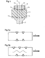
- the bone anchoring device comprises a bone anchoring element 1 in the form of a monoaxial bone screw having a shank 2 with a bone thread and a tip at one end and a receiving part 3 at the opposite end.
- the receiving part 3 is substantially cylindrically-shaped and comprises a substantially U-shaped recess 4 forming two free legs 5, 6.
- An internal thread 7 is provided on the legs.
- the bottom of the U-shaped recess forms a seat 8 for receiving a rod 9.
- the rod 9 is used to connect several bone anchoring elements.
- locking element in the form of an inner screw 10 is provided which can be screwed-in between the legs 5, 6.
- a plurality of rib-like projections 11 are provided on the surface of the seat 8.
- the rib-like projections 11 extend in a direction perpendicular to the longitudinal axis L of the recess 4 and hence extend perpendicular to the longitudinal axis L R of the rod 9.
- the projections 11 have a substantially triangular cross-section with a rounded tip.
- the projections 11 have such a length that they form a U-shape corresponding to the seat 8. They end at a distance from the internal thread 7.
- Each or several of the rib-like projections 11 may run out on one or on either side in groove-like recesses which provide depressions in the surface of the seat. Alternatively, one or several depressions in the surface of the seat which adjoins one or several of the projections can be provided.
- the rod 9 is made of an elastic flexible biocompatible material, preferably of plastics.
- the rod 9 is made of an elastomer material on the basis of polycarbonate-polyurethane or polycarbonateurethane (PCU).
- PCU polycarbonateurethane
- the inner screw 10 which is to be screwed between the legs 5, 6 comprises at its side 10a facing the rod 9 a ring shaped projection 12 in form of an annular rib with a central cavity.
- the ring-shaped projection 12 has a cross-section which is similar to the cross-section of the rib-like projections 11 of the seat.
- the diameter of the ring-shaped projection 12 is such that the contact areas 12a, 12b and the contact areas 11a and 11b of the two outer rib-like projections are located on opposite sides of the surface of the rod 9 on a vertical line Va, Vb which is parallel to the central axis C of the receiving part 3, respectively.
- the bone anchoring element 1 and the inner screw 10 are made of a biocompatible rigid material, preferably of a metal, such as titanium or a titanium alloy.
- first at least two bone anchoring elements 1 are screwed into adjacent vertebrae, for example into the pedicles of the vertebrae.
- rod 9 is inserted into the receiving parts 3 until it is seated in the seat 8.
- the rod is locked in its position by screwing-in the inner screw 10. If the inner screw 10 is not yet tightened, the position of the rod can still be adjusted in a stepless manner, since the rod has a smooth surface.
- the inner screw 10 is tightened until the ring-shaped projection 12 comes into contact with the surface of the rod. As can be seen in Fig. 4 the opposite portions 12a and 12b of the ring-shaped projection are pressed down on the surface of the rod.
- the diameter of the ring-shaped projection 12 can be equal or larger than the distance between the outmost rib-like projections 11.
- one arrangement of the engagement structure formed by the projections of the seat and the engagement structure formed by the projection on the locking element at corresponding locations on opposite surface portions of the rod provides a form-fit connection which is resistant to a force F acting in the longitudinal direction of the rod 9.
- the ring-shaped projection of the inner screw makes it possible that the engagement structure is provided at the locking element itself instead of using a filling piece or pressure piece.
- Fig. 6 to 14 show a second embodiment of the bone anchoring device.
- the bone anchoring device comprises a bone anchoring element 20 in the form of a polyaxial bone screw having a screw element with a shank 21 with a bone thread, a tip at one end and a spherical head 22 at the opposite end.
- a recess 23 for engagement with the screwing-in tool is provided at the side of the head 22 which is opposite to the shank.
- the bone anchoring element 20 further comprises a receiving part 25 which has a first end 26 and a second end 27 opposite to the first end and a central axis C intersecting the plane of the first end and the second end. Coaxially with the central axis C a bore 29 is provided which extends from the first end to predetermined distance from the second end. At the second end 27 an opening 30 is provided the diameter of which is smaller than the diameter of the bore 29.
- the head 22 is pivotably held in the receiving part 25 with the shank extending through the opening 30.
- the receiving part 25 further has a substantially U-shaped recess 31 which starts at the first end 26 and extends in the direction of the second end 27.
- a substantially U-shaped recess 31 which starts at the first end 26 and extends in the direction of the second end 27.
- two free legs 32, 33 are formed which have an internal thread 34.
- a pressure element 35 is provided which a substantially cylindrical construction with an outer diameter which is only slightly smaller than the inner diameter of the bore 29 to allow the pressure element 35 to be introduced into the bore 29 of the receiving part and to be moved in the axial direction.
- the pressure element 35 On its lower side facing towards the second end 27 the pressure element 35 comprises a spherical recess 36 the radius of which corresponds to the radius of the spherical thread 22 of the screw element.
- On the opposite side pressure element 35 comprises a U-shaped recess 37 extending transversely to the central axis C. The lateral diameter of this recess is selected such that the rod 9 which is to be received in the receiving part 3 can be inserted into the recess 37 and guided laterally therein.
- the depth of the U-shaped recess 37 is selected such that in an assembled state when the rod is placed into the U-shaped recess 37, legs 37a, 37b of the recess extend up to the upper surface of the rod.
- the depth of the recess 37 is equal to the diameter of the rod 9.
- the lateral diameter of the recess in the area of the ribs and/or the depth of the recess 37 can be slightly larger than the diameter of the rod to allow local plastic flow of the material of the rod.
- the bottom 38 of the U-shaped recess of the pressure element 35 forms a seat for the rod 9. Similar to the first embodiment a plurality of rib-like projections 39 are provided on the surface of the seat 38. In the embodiment shown, there are two rib-like projections 39, extending in a direction transversely to the longitudinal axis I of the U-shaped recess 37 and, therefore, transversely to the longitudinal axis L R of the rod 9. Furthermore, the pressure element comprises a coaxial bore 40 to allow access to the recess 23 of the head 22 with a screwing-in tool.
- the locking element is the inner screw 10 as in the first embodiment, which has the ring-shaped projection 12 on its side 10a facing the rod 9.
- the dimensions of the ring-shaped projeciton 12 is such that, as shown in Fig. 8 , the contact areas 12a and 12b of the ring-shaped projection 12 with the rod are located at positions corresponding to the contact areas 39a, 39b of the rib-like projections of the pressure element on opposite sides of the rod.
- the dimensions of the pressure element 35 and the inner screw 10 are such that in the assembled state the lower side 10a of the inner screw rests on the upper end surface 41 a, 41 b of the legs of the pressure element.
- the dimensions of the projections 39 of the pressure element and the ring-shaped projection 12 of the inner screw are such that safe fixation by means of a press-fit with indirect form-fit is achieved without harming the integrity of the surface of the rod.
- the bone anchoring element 20 is preassembled, i.e. the bone screw is pivotably held in the receiving part and the pressure element is inserted and slightly held in a position in which its U-shaped recess is aligned with the U-shaped recess of the receiving part.
- the bone anchoring element is screwed into the bone and the angular position of the receiving part relative to the bone screw is adjusted.
- the rod 9 is inserted and the inner screw 10 tightened down until it clamps the rod.
- the function of the clamping is the same as in the first embodiment.
- the number of the rib-like projections may vary. Instead of having only rib-like projections provided at the surface of the locking element and the seat a combination of projections and depressions can be provided. Hence, this allows the material which is displaced when the projections press onto the surface of the rod to flow in the depressions to generate a form-fit connection.
- the volumes of projections and depressions are similar or have the same size such that after the flow of material is completed, the volume of the rod in a region of the connection with the receiving part has approximately the same size as before.
- the projections and/or depressions need not to have a rib- or groove-like structure but can have any shape.
- the projection which comes into contact with the surface of the rod can have another shape than a ring shape.
- at least one tooth should be provided which shaped so as to sink into the surface of the rod to create an indirect form-fit between the locking element and the rod or between the seat and the rod, respectively.
- a ring-shaped structure of the projection on the locking element is preferable, since it facilitates tightening of the locking element by means of a turning motion.
- the rod needs not to have a circular cross section. It can have an oval rectangular or square cross section.
- a cap can be provided for closing the bore after the bone anchoring element is screwed into the bone.
- the locking element can also be modified.
- the locking element can be a nut with a coaxial pin which is formed in one piece with the nut.
- the pin has the projection which comes into contact with the surface of the rod.
- the free legs of the receiving part have an external thread which cooperates with the thread of the nut.
- the bone anchoring element is introduced from the top into the receiving part.
- the bone anchoring element can also be introduces from the bottom of the receiving part if the receiving part is constructed to allow this.
- the head of the bone anchoring element and the shaft can be constructed as separate parts which can be assembled.
- the invention is not limited to screws as bone anchoring elements but can be realised with bone hooks or any other bone anchoring element.
Description
- The invention relates to a bone anchoring device according to the preamble of claim 1.
- Bone anchoring devices comprising a bone screw and a flexible rod which is made of an elastic material are known from
EP 1 364 622 A2 andEP 1 527 742 A1 . The rod has a corrugated surface which cooperates with a rib structure provided on the bottom of the receiving part of the bone screw to form a form-fit connection. The bone anchoring device according toEP 1 527 742 A1 additionally comprises a closure element which has a rib structure engaging the corrugated surface of the rod. The positioning of the corrugated surfaces of the rod relative to the rib structure requires a precise insertion of the rod into the receiving part to avoid tilting. Furthermore, a continuous positioning is not possible. This makes the adjustment of the position of the rod relative to the receiving part difficult and time consuming. -
US 2004/0138660 A1 discloses a locking cap assembly for locking a rigid rod to a receiving body of a bone screw. The locking cap assembly includes an inner and an outer locking element. The outer locking element is a nut-like member and the inner locking element is rotatably connected to the outer locking element. The inner locking element has on its side facing the rod a ring-shaped deformable contacting element which comes into contact with the rod. Upon tightening of the outer locking element, the deformable element is deformed which provides feed-back to the surgeon to allow him to determine whether the locking cap assembly is tightened to the required extent. In one example, the deformable element is a deformable metallic ring which becomes cold welded to the rod. -
US-6,224,598 B1 discloses a generic bone anchoring device comprising an anchoring element comprising a shank to be anchored in a bone or a vertebra; a connection element for connecting at least two anchoring elements; a receiving part being connected to the shank for receiving the connection element and connecting the connection element to the shank; a seat for the connection element the seat being provided in the receiving part; a one piece locking element being rotatably engageable with the receiving part for fixation of the connection element in the seat; wherein at least the portion of the connection element which is received in the recess has a substantially smooth surface and wherein the locking element has an engagement structure which contacts the surface of the connection element. A sharp edged annular ring provides a three-point-support of the rigid and curved connection element. - Further bone anchoring devices having rigid connection elements are known from
EP-0 348 272 A1 ;US-6,652,526 B1 ;US2005/203518 A1 andEP-1 527 742 A1 , where the connection elements are either plastically deformed by an engagement with the locking element/receiving part (thereby, destroying the integral structure of the material of the connection element) or establish a form-fit connection by corresponding grooves and ribs. - It is the object of the present invention to provide a bone anchoring device having improved handling while simultaneously providing a safe locking when fixing the locking element.
- The object is solved by a bone anchoring device according to claim 1. Further developments are given in the dependent claims.
- The bone anchoring device has the advantage that during tightening of the locking element the deformation of the elastic material of the rod leads to an indirect or dynamic force-fit connection between the elastic rod, the receiving part and the locking element without harming the integral structure of the rod.
- Since the rod has a smooth surface, continuous positioning of the rod is possible.
- The bone anchoring device has furthermore the advantage that a flow of the material of the rod in a direction along the longitudinal axis of the rod is minimized.
- The fixation of the rod is achieved with a small number of parts. Therefore, the handling of the bone anchoring device during surgery is facilitated without loss of reliability of the fixation.
- Further features and advantages of the invention will become apparent and will be best understood by reference to the following detailed description of embodiments taken in conjunction with the accompanying drawings.
-
Fig. 1 shows a perspective exploded view of a first embodiment of the bone anchoring device. -
Fig. 2 shows the bone anchoring device ofFig. 1 in an assembled state. -
Fig. 3 shows a perspective view of the locking element of the bone anchoring device ofFig. 1 . -
Fig. 4 shows a sectional view of a portion of the bone anchoring device ofFig. 1 and 2 . -
Fig. 5a shows a schematic view of the fixation mechanism of the bone anchoring device according to the invention. -
Fig. 5b shows a schematic view of another fixation mechanism. -
Fig. 6 shows an perspective exploded view of a bone anchoring device according a second embodiment. -
Fig. 7 shows a perspective view of the bone anchoring device shown inFig. 6 in an assembled state. -
Fig. 8 shows a portion of the bone fixation device according toFig. 7 in an assembled state in a sectional view the section being taken along the rod axis. -
Fig. 9 shows a sectional view of the bone anchoring device ofFig. 8 along the line M-M. -
Fig. 10 shows a sectional view of the locking element of the second embodiment. -
Fig. 11 shows a perspective view of the pressure element of the bone anchoring device according to the second embodiment. -
Fig. 12 shows a top view of the pressure element shown inFig. 11 . -
Fig. 13 shows a side view of the pressure element shown inFig. 11.Fig. 14 shows a sectional view of the pressure element shown inFig. 11 along the line S-S inFig. 13 - As shown in
Figs. 1 to 4 the bone anchoring device according to a first embodiment comprises a bone anchoring element 1 in the form of a monoaxial bone screw having ashank 2 with a bone thread and a tip at one end and a receivingpart 3 at the opposite end. Thereceiving part 3 is substantially cylindrically-shaped and comprises a substantially U-shaped recess 4 forming twofree legs 5, 6. Aninternal thread 7 is provided on the legs. The bottom of the U-shaped recess forms aseat 8 for receiving arod 9. Therod 9 is used to connect several bone anchoring elements. To secure therod 9 in the recess 4 locking element in the form of aninner screw 10 is provided which can be screwed-in between thelegs 5, 6. - As can be seen in particular in
Figs. 1 and4 a plurality of rib-like projections 11 are provided on the surface of theseat 8. The rib-like projections 11 extend in a direction perpendicular to the longitudinal axis L of the recess 4 and hence extend perpendicular to the longitudinal axis LR of therod 9. In the embodiment shown theprojections 11 have a substantially triangular cross-section with a rounded tip. Theprojections 11 have such a length that they form a U-shape corresponding to theseat 8. They end at a distance from theinternal thread 7. Each or several of the rib-like projections 11 may run out on one or on either side in groove-like recesses which provide depressions in the surface of the seat. Alternatively, one or several depressions in the surface of the seat which adjoins one or several of the projections can be provided. - The
rod 9 is made of an elastic flexible biocompatible material, preferably of plastics. For example, therod 9 is made of an elastomer material on the basis of polycarbonate-polyurethane or polycarbonateurethane (PCU). Hence, the rod shows elastic deformation under applied external loads. - The
inner screw 10 which is to be screwed between thelegs 5, 6 comprises at itsside 10a facing the rod 9 a ringshaped projection 12 in form of an annular rib with a central cavity. As can be seen in particular inFig. 4 , the ring-shaped projection 12 has a cross-section which is similar to the cross-section of the rib-like projections 11 of the seat. When the ring-shaped projection 12 comes into contact with therod 9, twocontact areas shaped projection 12 is such that thecontact areas contact areas rod 9 on a vertical line Va, Vb which is parallel to the central axis C of thereceiving part 3, respectively. - The bone anchoring element 1 and the
inner screw 10 are made of a biocompatible rigid material, preferably of a metal, such as titanium or a titanium alloy. - In use, first at least two bone anchoring elements 1 are screwed into adjacent vertebrae, for example into the pedicles of the vertebrae. Thereafter
rod 9 is inserted into thereceiving parts 3 until it is seated in theseat 8. Thereafter the rod is locked in its position by screwing-in theinner screw 10. If theinner screw 10 is not yet tightened, the position of the rod can still be adjusted in a stepless manner, since the rod has a smooth surface. After adjusting the position of the rod theinner screw 10 is tightened until the ring-shapedprojection 12 comes into contact with the surface of the rod. As can be seen inFig. 4 theopposite portions like projections 11 are pressing on the surface of the rod from below. The projections do not harm the integrity of the surface of the rod. The rod begins to flow under applied pressure This material flow results in an indirect form-fit connection. The combination of direct frictional forces and indirect form-fit forces holds the rod in place. - The diameter of the ring-shaped
projection 12 can be equal or larger than the distance between the outmost rib-like projections 11.
As can be seen inFig. 5a , one arrangement of the engagement structure formed by the projections of the seat and the engagement structure formed by the projection on the locking element at corresponding locations on opposite surface portions of the rod provides a form-fit connection which is resistant to a force F acting in the longitudinal direction of therod 9. - An alternating arrangement of the projections of the seat and that of the locking element with respect to the rod as shown in
Fig. 5b , also leads to an indirect form-fit connection as described above, which, however, is less resistant to a force F acting in the axial direction of the rod. In case of a large force F, the connection shown inFig. 5b cannot prohibit a wavy-like movement of the rod and hence provides less fixation of the rod. - The ring-shaped projection of the inner screw makes it possible that the engagement structure is provided at the locking element itself instead of using a filling piece or pressure piece.
-
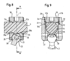
Fig. 6 to 14 show a second embodiment of the bone anchoring device. The bone anchoring device comprises abone anchoring element 20 in the form of a polyaxial bone screw having a screw element with ashank 21 with a bone thread, a tip at one end and aspherical head 22 at the opposite end. Arecess 23 for engagement with the screwing-in tool is provided at the side of thehead 22 which is opposite to the shank. - The
bone anchoring element 20 further comprises a receivingpart 25 which has afirst end 26 and asecond end 27 opposite to the first end and a central axis C intersecting the plane of the first end and the second end. Coaxially with the central axis C abore 29 is provided which extends from the first end to predetermined distance from the second end. At thesecond end 27 anopening 30 is provided the diameter of which is smaller than the diameter of thebore 29. Thehead 22 is pivotably held in the receivingpart 25 with the shank extending through theopening 30. - The receiving
part 25 further has a substantiallyU-shaped recess 31 which starts at thefirst end 26 and extends in the direction of thesecond end 27. By means of the U-shaped recess twofree legs internal thread 34. - A
pressure element 35 is provided which a substantially cylindrical construction with an outer diameter which is only slightly smaller than the inner diameter of thebore 29 to allow thepressure element 35 to be introduced into thebore 29 of the receiving part and to be moved in the axial direction. On its lower side facing towards thesecond end 27 thepressure element 35 comprises aspherical recess 36 the radius of which corresponds to the radius of thespherical thread 22 of the screw element. On the oppositeside pressure element 35 comprises aU-shaped recess 37 extending transversely to the central axis C. The lateral diameter of this recess is selected such that therod 9 which is to be received in the receivingpart 3 can be inserted into therecess 37 and guided laterally therein. The depth of theU-shaped recess 37 is selected such that in an assembled state when the rod is placed into theU-shaped recess 37,legs recess 37 is equal to the diameter of therod 9. The lateral diameter of the recess in the area of the ribs and/or the depth of therecess 37 can be slightly larger than the diameter of the rod to allow local plastic flow of the material of the rod. - The bottom 38 of the U-shaped recess of the
pressure element 35 forms a seat for therod 9. Similar to the first embodiment a plurality of rib-like projections 39 are provided on the surface of theseat 38. In the embodiment shown, there are two rib-like projections 39, extending in a direction transversely to the longitudinal axis I of theU-shaped recess 37 and, therefore, transversely to the longitudinal axis LR of therod 9. Furthermore, the pressure element comprises acoaxial bore 40 to allow access to therecess 23 of thehead 22 with a screwing-in tool. - The locking element is the
inner screw 10 as in the first embodiment, which has the ring-shapedprojection 12 on itsside 10a facing therod 9. The dimensions of the ring-shapedprojeciton 12 is such that, as shown inFig. 8 , thecontact areas projection 12 with the rod are located at positions corresponding to thecontact areas - The dimensions of the
pressure element 35 and theinner screw 10 are such that in the assembled state thelower side 10a of the inner screw rests on the upper end surface 41 a, 41 b of the legs of the pressure element. The dimensions of theprojections 39 of the pressure element and the ring-shapedprojection 12 of the inner screw are such that safe fixation by means of a press-fit with indirect form-fit is achieved without harming the integrity of the surface of the rod. - In use, the
bone anchoring element 20 is preassembled, i.e. the bone screw is pivotably held in the receiving part and the pressure element is inserted and slightly held in a position in which its U-shaped recess is aligned with the U-shaped recess of the receiving part. The bone anchoring element is screwed into the bone and the angular position of the receiving part relative to the bone screw is adjusted. Therod 9 is inserted and theinner screw 10 tightened down until it clamps the rod. The function of the clamping is the same as in the first embodiment. When tightening the inner screw presses onto the upper end surface 41 a, 41 b of the pressure element and thus presses down the pressure element onto thehead 22 to lock the angular position of the head in the receiving part. - Since the
lower side 10a of the inner screw rests on theupper end surface elastic rod 9 when theprojections head 22 in the receivingpart 25. - As the locking of the rod is achieved by pressing the
projections - Modifications of the above described embodiments are possible.
- The number of the rib-like projections may vary. Instead of having only rib-like projections provided at the surface of the locking element and the seat a combination of projections and depressions can be provided. Hence, this allows the material which is displaced when the projections press onto the surface of the rod to flow in the depressions to generate a form-fit connection. Advantageously, the volumes of projections and depressions are similar or have the same size such that after the flow of material is completed, the volume of the rod in a region of the connection with the receiving part has approximately the same size as before.
- The projections and/or depressions need not to have a rib- or groove-like structure but can have any shape. The projection which comes into contact with the surface of the rod can have another shape than a ring shape. Dependent on the external load, at least one tooth should be provided which shaped so as to sink into the surface of the rod to create an indirect form-fit between the locking element and the rod or between the seat and the rod, respectively. A ring-shaped structure of the projection on the locking element is preferable, since it facilitates tightening of the locking element by means of a turning motion.
- The rod needs not to have a circular cross section. It can have an oval rectangular or square cross section.
- The second embodiment, to avoid a flowing out of material through the
bore 40 provided in the pressure element, a cap can be provided for closing the bore after the bone anchoring element is screwed into the bone. - The locking element can also be modified. For example, the locking element can be a nut with a coaxial pin which is formed in one piece with the nut. The pin has the projection which comes into contact with the surface of the rod. In this case, the free legs of the receiving part have an external thread which cooperates with the thread of the nut. In the second embodiment described above the bone anchoring element is introduced from the top into the receiving part. However, the bone anchoring element can also be introduces from the bottom of the receiving part if the receiving part is constructed to allow this.
- The head of the bone anchoring element and the shaft can be constructed as separate parts which can be assembled.
- The invention is not limited to screws as bone anchoring elements but can be realised with bone hooks or any other bone anchoring element.
Claims (18)
- Bone anchoring device comprising
an anchoring element (1; 20) comprising a shank (2; 21) to be anchored in a bone or a vertebra;
a connection element (9) for connecting at least two anchoring elements;
a receiving part (3; 25) being connected to the shank for receiving the connection element and connecting the connection element to the shank;
a seat (8; 38) for the connection element the seat being provided in the receiving part;
a one piece locking element (10) being rotatably engageable with the receiving part for fixation of the connection element in the seat;
wherein
at least the portion of the connection element (9) which is received in the recess has a substantially smooth surface and wherein the locking element (10) has an engagement structure (12) which contacts the surface of the connection element,
characterized in that
the connection element (9) is made of an elastic material which is elastically deformed by pressing the engagement structure (12) against the connection element (9). - The bone anchoring device of claim 1, wherein the seat (8; 38) comprises an engagement structure (11; 39) which contacts the surface of the connection element (9).
- The bone anchoring device of claim 2, wherein the engagement structure (12) of the locking element (10) and the engagement structure (11; 39) of the seat (8; 38) are arranged on corresponding positions on opposite sides of the connection element.
- The bone anchoring device according to one of claims 1 to 3, wherein the engagement structure (11; 39) of the seat (8; 38) is an elongate projection which extends in a direction transversely to a longitudinal direction of the connection element.
- The bone anchoring device according to one of claims 1 to 4, wherein the receiving part (3; 25) has a substantially U-shaped recess (4; 31) forming two open legs with an inner thread provided on the legs and wherein the locking element (10) is an inner screw to be screwed-in between the legs.
- The bone anchoring device according to claim 5, wherein the engagement structure of the locking element (10) is a ring-shaped projection (12).
- The bone anchoring device according to one of claims 1 to 6, wherein the engagement structures comprise projections.
- The bone anchoring device according to one of claims 1 to 7, wherein the engagement structures comprise depressions.
- The bone anchoring device of one of claims 1 to 8, wherein the receiving part (3) has a substantially U-shaped recess (4) forming two open legs (6, 7) and wherein the seat (8) is provided at the bottom of the recess.
- The bone anchoring device of one of claims 1 to 8, wherein the bone anchoring element (20) is pivotably connected to the receiving part (25) and wherein the seat (38) is provided in a pressure element (35) which is movable in the receiving part and locks the angular position of the bone anchoring element if pressure is exerted on the pressure element.
- The bone anchoring device according to one of claims 1 to 10, wherein the connection element is made of an elastomer material.
- The bone anchoring device according to one of claims 1 to 11, wherein the connection element is a rod.
- The bone anchoring device according to one of claims 1 to 12, wherein the surface of the connection element (9) is without projections and/or depressions.
- The bone anchoring device according to one of claims 1 to 13, wherein the engagement structure of the locking element engages the surface of the connection element to create an indirect form-fit connection.
- The bone anchoring device according to one of claims 2 to 13, wherein the engagement structure of the seat engages the surface of the connection element to create an indirect form-fit connection.
- The bone anchoring device according to one of claims 1 to 15 wherein the locking of the connection element in the receiving part is achieved by a frictional connection with a portion of an indirect form-fit connection of the locking element with the connection element.
- The bone anchoring device of one of claims 1 to 16, wherein the connection between the locking element and the receiving part is a threaded connection.
- The bone anchoring device of one of claims 1 to 17, wherein the rod is clamped between the seat and the locking element and wherein a contour of the seat and a contour of the locking element deviate from the contour of the rod.
Priority Applications (9)
| Application Number | Priority Date | Filing Date | Title |
|---|---|---|---|
| EP06019341A EP1900334B2 (en) | 2006-09-15 | 2006-09-15 | Bone anchoring device |
| DE602006010556T DE602006010556D1 (en) | 2006-09-15 | 2006-09-15 | Bone anchoring device |
| ES06019341T ES2336815T5 (en) | 2006-09-15 | 2006-09-15 | Bone anchoring device |
| TW096133972A TWI413505B (en) | 2006-09-15 | 2007-09-12 | Bone anchoring device |
| CN2007101489373A CN101143108B (en) | 2006-09-15 | 2007-09-12 | Bone anchoring device |
| US11/854,508 US8568458B2 (en) | 2006-09-15 | 2007-09-12 | Bone anchoring device |
| JP2007236712A JP5361161B2 (en) | 2006-09-15 | 2007-09-12 | Bone fixation device |
| KR20070092646A KR101486978B1 (en) | 2006-09-15 | 2007-09-12 | Bone anchoring device |
| US13/613,739 US20130066381A1 (en) | 2006-09-15 | 2012-09-13 | Bone anchoring device |
Applications Claiming Priority (1)
| Application Number | Priority Date | Filing Date | Title |
|---|---|---|---|
| EP06019341A EP1900334B2 (en) | 2006-09-15 | 2006-09-15 | Bone anchoring device |
Publications (3)
| Publication Number | Publication Date |
|---|---|
| EP1900334A1 EP1900334A1 (en) | 2008-03-19 |
| EP1900334B1 true EP1900334B1 (en) | 2009-11-18 |
| EP1900334B2 EP1900334B2 (en) | 2013-01-16 |
Family
ID=37695933
Family Applications (1)
| Application Number | Title | Priority Date | Filing Date |
|---|---|---|---|
| EP06019341A Not-in-force EP1900334B2 (en) | 2006-09-15 | 2006-09-15 | Bone anchoring device |
Country Status (7)
| Country | Link |
|---|---|
| US (2) | US8568458B2 (en) |
| EP (1) | EP1900334B2 (en) |
| JP (1) | JP5361161B2 (en) |
| CN (1) | CN101143108B (en) |
| DE (1) | DE602006010556D1 (en) |
| ES (1) | ES2336815T5 (en) |
| TW (1) | TWI413505B (en) |
Families Citing this family (34)
| Publication number | Priority date | Publication date | Assignee | Title |
|---|---|---|---|---|
| US7967850B2 (en) | 2003-06-18 | 2011-06-28 | Jackson Roger P | Polyaxial bone anchor with helical capture connection, insert and dual locking assembly |
| US7776067B2 (en) | 2005-05-27 | 2010-08-17 | Jackson Roger P | Polyaxial bone screw with shank articulation pressure insert and method |
| US8936623B2 (en) | 2003-06-18 | 2015-01-20 | Roger P. Jackson | Polyaxial bone screw assembly |
| US8366753B2 (en) | 2003-06-18 | 2013-02-05 | Jackson Roger P | Polyaxial bone screw assembly with fixed retaining structure |
| US9393047B2 (en) | 2009-06-15 | 2016-07-19 | Roger P. Jackson | Polyaxial bone anchor with pop-on shank and friction fit retainer with low profile edge lock |
| US8444681B2 (en) | 2009-06-15 | 2013-05-21 | Roger P. Jackson | Polyaxial bone anchor with pop-on shank, friction fit retainer and winged insert |
| CH705709B1 (en) * | 2005-08-29 | 2013-05-15 | Bird Biedermann Ag | Spinal implant. |
| DE502006002049D1 (en) * | 2005-09-13 | 2008-12-24 | Bird Biedermann Ag | Dynamic clamping device for spinal implant |
| GB0521582D0 (en) * | 2005-10-22 | 2005-11-30 | Depuy Int Ltd | An implant for supporting a spinal column |
| GB0521585D0 (en) * | 2005-10-22 | 2005-11-30 | Depuy Int Ltd | A spinal support rod |
| DE602005008752D1 (en) * | 2005-11-17 | 2008-09-18 | Biedermann Motech Gmbh | Polyaxial screw for flexible rod |
| GB0600662D0 (en) * | 2006-01-13 | 2006-02-22 | Depuy Int Ltd | Spinal support rod kit |
| US8348952B2 (en) | 2006-01-26 | 2013-01-08 | Depuy International Ltd. | System and method for cooling a spinal correction device comprising a shape memory material for corrective spinal surgery |
| EP1815812B1 (en) * | 2006-02-03 | 2009-07-29 | Spinelab AG | Spinal implant |
| ES2392351T3 (en) * | 2007-02-23 | 2012-12-07 | Biedermann Technologies Gmbh & Co. Kg | Device to stabilize vertebrae |
| ES2375539T3 (en) * | 2007-07-20 | 2012-03-01 | Biedermann Motech Gmbh | BONE ANCHORAGE DEVICE. |
| GB0720762D0 (en) | 2007-10-24 | 2007-12-05 | Depuy Spine Sorl | Assembly for orthopaedic surgery |
| DE602008002815D1 (en) * | 2008-03-28 | 2010-11-11 | Biedermann Motech Gmbh | Bone anchoring device |
| WO2009124196A2 (en) * | 2008-04-03 | 2009-10-08 | Life Spine, Inc. | Top loading polyaxial spine screw assembly with one step lockup |
| US20090264931A1 (en) * | 2008-04-18 | 2009-10-22 | Warsaw Orthopedic, Inc. | Implantable Article for Use with an Anchor and a Non-Metal Rod |
| EP2135574B1 (en) * | 2008-06-19 | 2011-10-12 | BIEDERMANN MOTECH GmbH | Bone anchoring assembly |
| CA2739997C (en) | 2008-08-01 | 2013-08-13 | Roger P. Jackson | Longitudinal connecting member with sleeved tensioned cords |
| EP2160988B1 (en) | 2008-09-04 | 2012-12-26 | Biedermann Technologies GmbH & Co. KG | Rod-shaped implant in particular for stabilizing the spinal column and stabilization device including such a rod-shaped implant |
| IT1394182B1 (en) * | 2009-05-07 | 2012-06-01 | Nardi | COUPLING GROUP, PARTICULARLY FOR DENTAL IMPLANTS |
| US8998959B2 (en) | 2009-06-15 | 2015-04-07 | Roger P Jackson | Polyaxial bone anchors with pop-on shank, fully constrained friction fit retainer and lock and release insert |
| CN103826560A (en) | 2009-06-15 | 2014-05-28 | 罗杰.P.杰克逊 | Polyaxial bone anchor with pop-on shank and winged insert with friction fit compressive collet |
| US20110029018A1 (en) * | 2009-07-30 | 2011-02-03 | Warsaw Othropedic, Inc | Variable resistance spinal stablization systems and methods |
| KR101056120B1 (en) | 2011-01-14 | 2011-08-11 | (주)비엠코리아 | Screw for fixing rod and apparatus for spinal fixation using the same |
| ES2418604T3 (en) * | 2011-08-18 | 2013-08-14 | Biedermann Technologies Gmbh & Co. Kg | Polyaxial bone anchoring device |
| ES2569854T3 (en) | 2011-09-28 | 2016-05-12 | Biedermann Technologies Gmbh & Co. Kg | Bone anchor set |
| US9295488B2 (en) | 2012-08-09 | 2016-03-29 | Wilson T. Asfora | Joint fusion |
| CN104958100A (en) * | 2015-05-25 | 2015-10-07 | 创生医疗器械(中国)有限公司 | Anti-screwing jackscrew for pedicle screw |
| EP3287089B1 (en) * | 2016-08-24 | 2019-07-24 | Biedermann Technologies GmbH & Co. KG | Polyaxial bone anchoring device and system of an instrument and a polyaxial bone anchoring device |
| US20200390472A1 (en) * | 2019-02-27 | 2020-12-17 | Orthopediatrics Corp. | Bone anchor with cord retention features |
Family Cites Families (32)
| Publication number | Priority date | Publication date | Assignee | Title |
|---|---|---|---|---|
| US4743260A (en) * | 1985-06-10 | 1988-05-10 | Burton Charles V | Method for a flexible stabilization system for a vertebral column |
| FR2633177B1 (en) * | 1988-06-24 | 1991-03-08 | Fabrication Materiel Orthopedi | IMPLANT FOR A SPINAL OSTEOSYNTHESIS DEVICE, ESPECIALLY IN TRAUMATOLOGY |
| WO1991016020A1 (en) * | 1990-04-26 | 1991-10-31 | Danninger Medical Technology, Inc. | Transpedicular screw system and method of use |
| CH681853A5 (en) * | 1990-08-21 | 1993-06-15 | Synthes Ag | |
| FR2676911B1 (en) * | 1991-05-30 | 1998-03-06 | Psi Ste Civile Particuliere | INTERVERTEBRAL STABILIZATION DEVICE WITH SHOCK ABSORBERS. |
| US5257993A (en) * | 1991-10-04 | 1993-11-02 | Acromed Corporation | Top-entry rod retainer |
| DE59301618D1 (en) * | 1992-06-04 | 1996-03-28 | Synthes Ag | Osteosynthetic fastener |
| US6077262A (en) * | 1993-06-04 | 2000-06-20 | Synthes (U.S.A.) | Posterior spinal implant |
| EP0689798B1 (en) * | 1994-06-30 | 2000-10-18 | Sulzer Orthopädie AG | Device for connecting vertebrae |
| US5591235A (en) | 1995-03-15 | 1997-01-07 | Kuslich; Stephen D. | Spinal fixation device |
| US6749361B2 (en) * | 1997-10-06 | 2004-06-15 | Werner Hermann | Shackle element for clamping a fixation rod, a method for making a shackle element, a hook with a shackle element and a rode connector with a shackle element |
| DE19818765A1 (en) * | 1998-04-07 | 1999-10-14 | Schaefer Micomed Gmbh | Synthetic bone device for fixing bone fractures |
| US6565565B1 (en) * | 1998-06-17 | 2003-05-20 | Howmedica Osteonics Corp. | Device for securing spinal rods |
| US6224598B1 (en) | 2000-02-16 | 2001-05-01 | Roger P. Jackson | Bone screw threaded plug closure with central set screw |
| KR200200582Y1 (en) * | 2000-03-15 | 2000-10-16 | 최길운 | Prosthesis for connecting bone |
| JP2002320622A (en) * | 2001-04-26 | 2002-11-05 | Kyocera Corp | Device for vertebral bone rectification |
| US6478797B1 (en) * | 2001-05-16 | 2002-11-12 | Kamaljit S. Paul | Spinal fixation device |
| US6793657B2 (en) * | 2001-09-10 | 2004-09-21 | Solco Biomedical Co., Ltd. | Spine fixing apparatus |
| US6652526B1 (en) | 2001-10-05 | 2003-11-25 | Ruben P. Arafiles | Spinal stabilization rod fastener |
| US6783527B2 (en) * | 2001-10-30 | 2004-08-31 | Sdgi Holdings, Inc. | Flexible spinal stabilization system and method |
| US6966910B2 (en) * | 2002-04-05 | 2005-11-22 | Stephen Ritland | Dynamic fixation device and method of use |
| DE50300788D1 (en) * | 2002-05-21 | 2005-08-25 | Spinelab Gmbh Wabern | Elastic stabilization system for spinal columns |
| US6730089B2 (en) * | 2002-08-26 | 2004-05-04 | Roger P. Jackson | Nested closure plug and set screw with break-off heads |
| US6843791B2 (en) * | 2003-01-10 | 2005-01-18 | Depuy Acromed, Inc. | Locking cap assembly for spinal fixation instrumentation |
| ES2269957T3 (en) | 2003-10-31 | 2007-04-01 | Spinelab Ag | MECHANISM OF CLOSURE OF PEDICULAR SCREWS DPARA THE FIXATION OF ELASTIC RODS. |
| TW200518711A (en) * | 2003-12-11 | 2005-06-16 | A Spine Holding Group Corp | Rotation buckling ball-head spine restoring equipment |
| WO2005084566A1 (en) | 2004-03-04 | 2005-09-15 | Synthes Gmbh | Connecting rod for bone connecting elements |
| DE102004010844A1 (en) | 2004-03-05 | 2005-10-06 | Biedermann Motech Gmbh | Stabilizing device for the dynamic stabilization of vertebrae or bones and rod-shaped element for such a stabilization device |
| US7857834B2 (en) | 2004-06-14 | 2010-12-28 | Zimmer Spine, Inc. | Spinal implant fixation assembly |
| CH705709B1 (en) * | 2005-08-29 | 2013-05-15 | Bird Biedermann Ag | Spinal implant. |
| DE502006002049D1 (en) * | 2005-09-13 | 2008-12-24 | Bird Biedermann Ag | Dynamic clamping device for spinal implant |
| DE602005008752D1 (en) * | 2005-11-17 | 2008-09-18 | Biedermann Motech Gmbh | Polyaxial screw for flexible rod |
-
2006
- 2006-09-15 ES ES06019341T patent/ES2336815T5/en active Active
- 2006-09-15 DE DE602006010556T patent/DE602006010556D1/en active Active
- 2006-09-15 EP EP06019341A patent/EP1900334B2/en not_active Not-in-force
-
2007
- 2007-09-12 CN CN2007101489373A patent/CN101143108B/en not_active Expired - Fee Related
- 2007-09-12 US US11/854,508 patent/US8568458B2/en not_active Expired - Fee Related
- 2007-09-12 JP JP2007236712A patent/JP5361161B2/en not_active Expired - Fee Related
- 2007-09-12 TW TW096133972A patent/TWI413505B/en not_active IP Right Cessation
-
2012
- 2012-09-13 US US13/613,739 patent/US20130066381A1/en not_active Abandoned
Also Published As
| Publication number | Publication date |
|---|---|
| EP1900334B2 (en) | 2013-01-16 |
| TWI413505B (en) | 2013-11-01 |
| JP2008068091A (en) | 2008-03-27 |
| CN101143108A (en) | 2008-03-19 |
| US20130066381A1 (en) | 2013-03-14 |
| DE602006010556D1 (en) | 2009-12-31 |
| CN101143108B (en) | 2012-07-04 |
| ES2336815T5 (en) | 2013-05-16 |
| US8568458B2 (en) | 2013-10-29 |
| JP5361161B2 (en) | 2013-12-04 |
| EP1900334A1 (en) | 2008-03-19 |
| US20080114404A1 (en) | 2008-05-15 |
| ES2336815T3 (en) | 2010-04-16 |
| TW200812542A (en) | 2008-03-16 |
Similar Documents
| Publication | Publication Date | Title |
|---|---|---|
| EP1900334B1 (en) | Bone anchoring device | |
| EP2135573B1 (en) | Bone anchoring device | |
| US7731749B2 (en) | Bone anchoring device | |
| EP1891904B1 (en) | Bone anchoring device | |
| EP1842503B1 (en) | Angled polyaxial bone anchoring device | |
| EP1839606B1 (en) | Locking assembly for securing a rod member in a receiver part for use in spinal or trauma surgery, bone anchoring device with such a locking assembly and tool therefor | |
| EP1743584B1 (en) | Bone anchoring device | |
| US20060271193A1 (en) | Device for connecting a longitudinal member to a bone | |
| EP1935358A1 (en) | Bone anchoring device | |
| KR101486978B1 (en) | Bone anchoring device | |
| KR101507574B1 (en) | Bone anchoring device |
Legal Events
| Date | Code | Title | Description |
|---|---|---|---|
| PUAI | Public reference made under article 153(3) epc to a published international application that has entered the european phase |
Free format text: ORIGINAL CODE: 0009012 |
|
| AK | Designated contracting states |
Kind code of ref document: A1 Designated state(s): CH DE ES FR GB IT LI |
|
| AX | Request for extension of the european patent |
Extension state: AL BA HR MK YU |
|
| 17P | Request for examination filed |
Effective date: 20080328 |
|
| 17Q | First examination report despatched |
Effective date: 20080430 |
|
| AKX | Designation fees paid |
Designated state(s): CH DE ES FR GB IT LI |
|
| GRAP | Despatch of communication of intention to grant a patent |
Free format text: ORIGINAL CODE: EPIDOSNIGR1 |
|
| GRAS | Grant fee paid |
Free format text: ORIGINAL CODE: EPIDOSNIGR3 |
|
| GRAA | (expected) grant |
Free format text: ORIGINAL CODE: 0009210 |
|
| AK | Designated contracting states |
Kind code of ref document: B1 Designated state(s): CH DE ES FR GB IT LI |
|
| REG | Reference to a national code |
Ref country code: GB Ref legal event code: FG4D |
|
| REG | Reference to a national code |
Ref country code: CH Ref legal event code: EP |
|
| REG | Reference to a national code |
Ref country code: CH Ref legal event code: NV Representative=s name: NOVAGRAAF INTERNATIONAL SA |
|
| REF | Corresponds to: |
Ref document number: 602006010556 Country of ref document: DE Date of ref document: 20091231 Kind code of ref document: P |
|
| REG | Reference to a national code |
Ref country code: ES Ref legal event code: FG2A Ref document number: 2336815 Country of ref document: ES Kind code of ref document: T3 |
|
| PLBI | Opposition filed |
Free format text: ORIGINAL CODE: 0009260 |
|
| PLAB | Opposition data, opponent's data or that of the opponent's representative modified |
Free format text: ORIGINAL CODE: 0009299OPPO |
|
| PLAX | Notice of opposition and request to file observation + time limit sent |
Free format text: ORIGINAL CODE: EPIDOSNOBS2 |
|
| 26 | Opposition filed |
Opponent name: SPINELAB AG Effective date: 20100816 |
|
| R26 | Opposition filed (corrected) |
Opponent name: SPINELAB AG Effective date: 20100816 |
|
| PLAF | Information modified related to communication of a notice of opposition and request to file observations + time limit |
Free format text: ORIGINAL CODE: EPIDOSCOBS2 |
|
| PLBB | Reply of patent proprietor to notice(s) of opposition received |
Free format text: ORIGINAL CODE: EPIDOSNOBS3 |
|
| REG | Reference to a national code |
Ref country code: CH Ref legal event code: PFA Owner name: BIEDERMANN MOTECH GMBH Free format text: BIEDERMANN MOTECH GMBH#BERTHA-VON-SUTTNER-STRASSE 23#78054 VS-SCHWENNINGEN (DE) -TRANSFER TO- BIEDERMANN MOTECH GMBH#BERTHA-VON-SUTTNER-STRASSE 23#78054 VS-SCHWENNINGEN (DE) |
|
| REG | Reference to a national code |
Ref country code: DE Ref legal event code: R082 Ref document number: 602006010556 Country of ref document: DE Representative=s name: PRUEFER & PARTNER GBR, DE |
|
| PUAH | Patent maintained in amended form |
Free format text: ORIGINAL CODE: 0009272 |
|
| STAA | Information on the status of an ep patent application or granted ep patent |
Free format text: STATUS: PATENT MAINTAINED AS AMENDED |
|
| 27A | Patent maintained in amended form |
Effective date: 20130116 |
|
| AK | Designated contracting states |
Kind code of ref document: B2 Designated state(s): CH DE ES FR GB IT LI |
|
| REG | Reference to a national code |
Ref country code: DE Ref legal event code: R102 Ref document number: 602006010556 Country of ref document: DE |
|
| REG | Reference to a national code |
Ref country code: DE Ref legal event code: R082 Ref document number: 602006010556 Country of ref document: DE Representative=s name: PRUEFER & PARTNER GBR, DE Effective date: 20121128 Ref country code: DE Ref legal event code: R081 Ref document number: 602006010556 Country of ref document: DE Owner name: BIEDERMANN TECHNOLOGIES GMBH & CO. KG, DE Free format text: FORMER OWNER: BIEDERMANN MOTECH GMBH, 78054 VILLINGEN-SCHWENNINGEN, DE Effective date: 20121128 Ref country code: DE Ref legal event code: R082 Ref document number: 602006010556 Country of ref document: DE Representative=s name: PRUEFER & PARTNER MBB PATENTANWAELTE RECHTSANW, DE Effective date: 20121128 |
|
| REG | Reference to a national code |
Ref country code: CH Ref legal event code: PUE Owner name: BIEDERMANN TECHNOLOGIES GMBH AND CO. KG, DE Free format text: FORMER OWNER: BIEDERMANN MOTECH GMBH AND CO. KG, DE Ref country code: CH Ref legal event code: PFA Owner name: BIEDERMANN MOTECH GMBH AND CO. KG, DE Free format text: FORMER OWNER: BIEDERMANN MOTECH GMBH, DE Ref country code: CH Ref legal event code: AELC |
|
| REG | Reference to a national code |
Ref country code: CH Ref legal event code: PFA Owner name: BIEDERMANN MOTECH GMBH AND CO. KG, DE Free format text: FORMER OWNER: BIEDERMANN MOTECH GMBH, DE Ref country code: ES Ref legal event code: PC2A Owner name: BIEDERMANN MOTECH GMBH & CO.KG. Effective date: 20130205 Ref country code: CH Ref legal event code: AELC Ref country code: CH Ref legal event code: PUE Owner name: BIEDERMANN TECHNOLOGIES GMBH AND CO. KG, DE Free format text: FORMER OWNER: BIEDERMANN MOTECH GMBH AND CO. KG, DE |
|
| REG | Reference to a national code |
Ref country code: DE Ref legal event code: R102 Ref document number: 602006010556 Country of ref document: DE Effective date: 20130116 |
|
| REG | Reference to a national code |
Ref country code: ES Ref legal event code: PC2A Owner name: BIEDERMANN TECHNOLOGIES GMBH & CO. KG Effective date: 20130311 |
|
| REG | Reference to a national code |
Ref country code: GB Ref legal event code: 732E Free format text: REGISTERED BETWEEN 20130307 AND 20130313 |
|
| REG | Reference to a national code |
Ref country code: FR Ref legal event code: CD Owner name: BIEDERMANN TECHNOLOGIES GMBH & CO.KG, DE Effective date: 20130329 Ref country code: FR Ref legal event code: TP Owner name: BIEDERMANN TECHNOLOGIES GMBH & CO.KG, DE Effective date: 20130329 |
|
| REG | Reference to a national code |
Ref country code: ES Ref legal event code: DC2A Ref document number: 2336815 Country of ref document: ES Kind code of ref document: T5 Effective date: 20130516 |
|
| REG | Reference to a national code |
Ref country code: FR Ref legal event code: PLFP Year of fee payment: 10 |
|
| PGFP | Annual fee paid to national office [announced via postgrant information from national office to epo] |
Ref country code: GB Payment date: 20150922 Year of fee payment: 10 Ref country code: CH Payment date: 20150922 Year of fee payment: 10 Ref country code: ES Payment date: 20150923 Year of fee payment: 10 |
|
| PGFP | Annual fee paid to national office [announced via postgrant information from national office to epo] |
Ref country code: FR Payment date: 20150923 Year of fee payment: 10 |
|
| PGFP | Annual fee paid to national office [announced via postgrant information from national office to epo] |
Ref country code: IT Payment date: 20150925 Year of fee payment: 10 Ref country code: DE Payment date: 20150929 Year of fee payment: 10 |
|
| REG | Reference to a national code |
Ref country code: DE Ref legal event code: R119 Ref document number: 602006010556 Country of ref document: DE |
|
| REG | Reference to a national code |
Ref country code: CH Ref legal event code: PL |
|
| GBPC | Gb: european patent ceased through non-payment of renewal fee |
Effective date: 20160915 |
|
| REG | Reference to a national code |
Ref country code: FR Ref legal event code: ST Effective date: 20170531 |
|
| PG25 | Lapsed in a contracting state [announced via postgrant information from national office to epo] |
Ref country code: CH Free format text: LAPSE BECAUSE OF NON-PAYMENT OF DUE FEES Effective date: 20160930 Ref country code: GB Free format text: LAPSE BECAUSE OF NON-PAYMENT OF DUE FEES Effective date: 20160915 Ref country code: LI Free format text: LAPSE BECAUSE OF NON-PAYMENT OF DUE FEES Effective date: 20160930 Ref country code: DE Free format text: LAPSE BECAUSE OF NON-PAYMENT OF DUE FEES Effective date: 20170401 Ref country code: FR Free format text: LAPSE BECAUSE OF NON-PAYMENT OF DUE FEES Effective date: 20160930 |
|
| PG25 | Lapsed in a contracting state [announced via postgrant information from national office to epo] |
Ref country code: IT Free format text: LAPSE BECAUSE OF NON-PAYMENT OF DUE FEES Effective date: 20160915 |
|
| PG25 | Lapsed in a contracting state [announced via postgrant information from national office to epo] |
Ref country code: ES Free format text: LAPSE BECAUSE OF NON-PAYMENT OF DUE FEES Effective date: 20160916 |
|
| REG | Reference to a national code |
Ref country code: ES Ref legal event code: FD2A Effective date: 20181129 |