EP1899224B1 - Breech loader - Google Patents
Breech loader Download PDFInfo
- Publication number
- EP1899224B1 EP1899224B1 EP06773301A EP06773301A EP1899224B1 EP 1899224 B1 EP1899224 B1 EP 1899224B1 EP 06773301 A EP06773301 A EP 06773301A EP 06773301 A EP06773301 A EP 06773301A EP 1899224 B1 EP1899224 B1 EP 1899224B1
- Authority
- EP
- European Patent Office
- Prior art keywords
- compartment
- meat
- pieces
- breech
- ram
- Prior art date
- Legal status (The legal status is an assumption and is not a legal conclusion. Google has not performed a legal analysis and makes no representation as to the accuracy of the status listed.)
- Not-in-force
Links
Images


Classifications
-
- B—PERFORMING OPERATIONS; TRANSPORTING
- B65—CONVEYING; PACKING; STORING; HANDLING THIN OR FILAMENTARY MATERIAL
- B65B—MACHINES, APPARATUS OR DEVICES FOR, OR METHODS OF, PACKAGING ARTICLES OR MATERIALS; UNPACKING
- B65B35/00—Supplying, feeding, arranging or orientating articles to be packaged
- B65B35/10—Feeding, e.g. conveying, single articles
- B65B35/20—Feeding, e.g. conveying, single articles by reciprocating or oscillatory pushers
-
- A—HUMAN NECESSITIES
- A22—BUTCHERING; MEAT TREATMENT; PROCESSING POULTRY OR FISH
- A22C—PROCESSING MEAT, POULTRY, OR FISH
- A22C11/00—Sausage making ; Apparatus for handling or conveying sausage products during manufacture
- A22C11/001—Machines for making skinless sausages, e.g. Frankfurters, Wieners
- A22C11/005—Apparatus for binding or tying sausages or meat, e.g. salami, rollades; Filling sausage products into sleeve netting
-
- A—HUMAN NECESSITIES
- A22—BUTCHERING; MEAT TREATMENT; PROCESSING POULTRY OR FISH
- A22C—PROCESSING MEAT, POULTRY, OR FISH
- A22C17/00—Other devices for processing meat or bones
- A22C17/0093—Handling, transporting or packaging pieces of meat
-
- B—PERFORMING OPERATIONS; TRANSPORTING
- B65—CONVEYING; PACKING; STORING; HANDLING THIN OR FILAMENTARY MATERIAL
- B65B—MACHINES, APPARATUS OR DEVICES FOR, OR METHODS OF, PACKAGING ARTICLES OR MATERIALS; UNPACKING
- B65B25/00—Packaging other articles presenting special problems
- B65B25/06—Packaging slices or specially-shaped pieces of meat, cheese, or other plastic or tacky products
- B65B25/065—Packaging slices or specially-shaped pieces of meat, cheese, or other plastic or tacky products of meat
-
- B—PERFORMING OPERATIONS; TRANSPORTING
- B65—CONVEYING; PACKING; STORING; HANDLING THIN OR FILAMENTARY MATERIAL
- B65B—MACHINES, APPARATUS OR DEVICES FOR, OR METHODS OF, PACKAGING ARTICLES OR MATERIALS; UNPACKING
- B65B9/00—Enclosing successive articles, or quantities of material, e.g. liquids or semiliquids, in flat, folded, or tubular webs of flexible sheet material; Subdividing filled flexible tubes to form packages
- B65B9/10—Enclosing successive articles, or quantities of material, in preformed tubular webs, or in webs formed into tubes around filling nozzles, e.g. extruded tubular webs
- B65B9/15—Enclosing successive articles, or quantities of material, in preformed tubular webs, or in webs formed into tubes around filling nozzles, e.g. extruded tubular webs the preformed tubular webs being stored on filling nozzles
Definitions
- This invention relates to the field of packaging material in nets. More particularly, the invention relates to the field of packaging edible food products, such as hams, in nets. More particularly, this invention relates to the field of packaging material such as hams in shirred, tubular casings and enclosing the products in netting.
- Some meat products are made of several pieces of whole-muscle meat. Boneless hams, for example, are made by combining several pieces of whole-muscle meat, which usually are irregularly-shaped pieces with one dimension much greater than the other two dimensions. Other types of meat products are made in a similar fashion.
- the several pieces were placed by hand in, for example, the feed tray (herein, the "breech"), of the netter shown in f the '477 patent.
- a ram pushes the meat through the guide tube of the netter, and ultimately the meat is wrapped in collagen film, encased in a net, and then processed.
- the process of placing the several meat pieces by hand is labor-intensive and time consuming.
- the process can be automated by bringing the pieces to the feed tray of the netter on a conveyor.
- the meat must be transferred, however, from the conveyor to the breech of the netter.
- the conveyor belt is higher than the breech of the netter. Accordingly, the conveyor drops the meat pieces into the breech of the netter. As the meat pieces reach the end of the conveyor, they roll off the end into the feed tray, which is of necessity slightly lower than the conveyor. This rolling disrupts the orientation of the meat.
- Placement and orientation of the several meat pieces is important. Most hams will be sliced for use by the consumer, either by a retailer or by the consumer at home. Accordingly, it is the cross-section of the ham that the ultimate consumer sees. Meat packers are trained to arrange the several pieces that will constitute the entire ham to minimize voids within the ham and to create a pleasing appearance once the ham is sliced. Moreover, some consumers want a layer of fat on the outside of the ham, which will retain moisture within the ham and provide flavor during cooking, but can be removed prior to consuming. Accordingly, it is important to place and orient the several meat pieces that will form the ham (or other meat product), and to place and orient the fat layer properly on the several muscles that make up the ham.
- GB 1,523,798 discloses an apparatus for packaging poultry specimens in which a poultry body is packaged in a bag by means of an apparatus comprising features that correspond with the preamble of claim 1.
- the present invention discloses a conveyor having compartments oriented on the belt.
- the conveyor is oriented to move transversely to the loading direction of a netter, and to be slightly below the height of the breech of the netter, so that the base of the compartments aligns with the breech.
- Pieces of meat (and fat, if necessary) are placed by hand within a compartment at a loading station.
- the conveyor then moves transversely to the breech of the netter, aligning the full compartment with the breech and bringing an empty compartment to the loading station.
- a ram pushes the meat out of the compartment and into the breech. From the time the pieces are placed and oriented in a compartment at a loading station, until they are wrapped and netted upon exit from the netter, they stay in the same position and in the same orientation relative to each other.
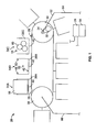
- the breech loader 20 of the preferred embodiment of the present invention is shown in elevation view in FIG. 1 , in plan view in FIG. 2 , and in side elevation in FIG. 3 .
- Loader 20 is designed for use with a netter 22, such as one described in United States Patent No. 6,883,297 .
- the moving parts of loader 20 and, preferably, netter 22 are controlled by a programmed logic controller, PLC 24.
- Loader 20 has a conveyor 26 with a belt 28 oriented on a plurality of rollers 30.
- An electric motor 32 attaches to one roller 30 through a chain 34 to drive the conveyor 26 which, in the orientation shown in FIG. 1 , moves in a counterclockwise direction.
- the direction of travel of conveyor 26 is transverse to the direction of feed to the breech 36 (feed tube or tray) of netter 22.
- a series of compartments 38A, 38B, 38C, etc., are attached to belt 28 by respective brackets 40.
- Each compartment 38 is spaced from the adjacent compartments, at least enough to prevent interference as the compartments 38 travel along the conveyor 26.
- Each compartment 38 has a generally rectangular base 42, with sides 44, 45, 46, and 47, as shown in FIG. 2 .
- Two side walls 48, 50 project from two opposing sides 44, 45 of base 42 and are transverse to the direction of travel of conveyor 26.
- Base 42 and side walls 48, 50 accordingly define a space 52 within each compartment 38 which is open on the two remaining sides 46, 47 of base 42, those sides 46, 47 being parallel to the direction of travel of conveyor 26.
- compartments 38A, 38B, and 38C are positioned at stations 54A, 54B, and 54C.
- compartment 54C for example, will move from station 54C to station 54B and then to station 54A.
- a compartment 38 moves around and under conveyor 26, empty, until it arrives again at station 54C.
- a ram 56 is positioned transverse to the direction of travel of belt 28 at station 54A and strokes co-axially with the direction of feed to breech 36.
- a compartment 38 (as illustrated, compartment 38A) arrives at station 54A, it is in alignment with the ram 56 and a breech 36, as will be explained.
- the ram 56 is then activated to push the contents of compartment 38 (in the preferred embodiment, composite meat 58 that has been packed into compartment 38, as will be explained) into breech 36.
- two workers are hand-loading pieces 60 of whole muscle and portions 60 of whole muscle and, if desired, fat, into compartments 38B and 38C at stations 54B and 54C. Those pieces and portions 60 will become composite meat 58.
- two compartments, 38B and 38C are being loaded at loading stations 54B and 54C, as ram 56 pushes the composite meat 58 of compartment 38A into netter 22.
- ram 56 pushes the composite meat 58 of compartment 38A into netter 22.
- the principle of the invention could be used with a single loading station 54B or with more than two loading stations 54B and 54C. For example, by lengthening conveyor 26, one or more extra loading stations 54D, 54E, etc., can be added.
- the conveyor 26 could feed to two parallel netters 22 and 22', by having, for example, two stations 54A and 54A', two stations 54B and 54B', etc., so that four workers pack pieces 60 into compartments 38, which then move two increments at a time to load the two netters 22 and 22'.
- a frame 62 having legs 64, 66, holds conveyor 26 off the floor of the facility.
- Frame 62 and legs 64, 66 are shown in FIG. 1 but are omitted, for clarity, in FIGS. 2 and 3 .
- Frame 62 is preferably adjustable or else custom made so that the base 42 of each compartment 38 aligns with the breech 36 of the netter 22 and ram 56, as shown in elevation view in FIG. 3 .
- Ram 56 is shown aligned with compartment 38A at station 38A.
- Ram 56 has a face plate 68 having a width just slightly less than the space between walls 48, 50.
- Face plate 68 has a height approximately the same as the height of walls 48, 50. Accordingly, face plate 68 is designed to sweep out space 52 when ram 56 is actuated.
- Face plate 68 is attached to cylinder 70. Any method of driving face plate 68 in a reciprocal manner will suffice, such as a rocker arm, a rail system, or a hydraulic piston.
- the pieces rest on base 42 and are constrained from lateral movement by walls 48, 50.
- a cover 74 preferably actuated by a second cylinder 76, is mounted above conveyor 26, as shown in FIG. 3 .
- Cover 74 can be mounted on frame 62, can be mounted on netter 22, or can be a separate structure. Cover 74 is designed so that, during the forward and reverse strokes of ram 56, cover 74 seals compartment 38A and breech 36, to keep workers' hands out of the way. Cover 74 can be a vertically-moving piece that descends onto compartment 38 at station 54A, as illustrated in FIG.
- cover 74 can be hinged, for example, to netter 22, to rotate from an open position to a closed position.
- cover 74 descends or rotates into its closed position, preventing any contact by workers with any moving parts.
- cover 74 rotates or ascends back to an open position, to allow the now-empty compartment 38 at station 54A to move with conveyor 26 and to allow a now-full compartment 38 to move into station 54A. Any other means to keep workers' hands safe will suffice.
- Cylinder 70 which, like second cylinder 76, is coupled to a compressed air source, such as plant air, a compressor, or bottled compressed air, actuates to drive face plate 68 through compartment 38A.
- a compressed air source such as plant air, a compressor, or bottled compressed air
- PLC 24 prevents operation of cylinder 70 unless cover 74 is closed.
- proximity switches 77 could be wired to cover 74, to be tripped by contact with a compartment 38, and wired to PLC 24 in a conventional manner to prevent actuation of cylinder 70 unless cover 74 is closed.
- Cylinder 70 When cylinder 70 actuates to drive a forward stroke, the movement of face plate 68 through space 52 pushes the composite meat 58 in compartment 38A out of compartment 38A and into breech 36. Cylinder 70 is designed to have a sufficient stroke to push the meat 58 completely out of compartment 38 and as far into breech 36 as is necessary to operate netter 22. When the meat 58 has been completely moved into breech 36, cylinder 70 retracts, leaving compartment 38A empty. When the workers have completed placing and orienting the pieces in the compartment 38 at station 54B, belt 28 moves again to bring the next full compartment (as illustrated, compartment 38B) to station 54A and in alignment with ram 56 and breech 36.
- the belt 28 of conveyor 26 is slightly below the level of breech 36.
- bracket 40 holds compartment 38 at the same level as breech 36.
- ram 56 can push the meat 58 directly into breech 36.
- the meat 58 does not roll off the end of the conveyor 26 in this system and therefore does not change position or orientation upon leaving the conveyor 26. Rather, since the force applied to the meat 58 is in the direction of travel through netter 22, the pieces 60 maintain their position and orientation relative to each other when pushed into breech 36. Inside breech 36, there is no room for the pieces 60 to change position or orientation. Accordingly, from the time the pieces 60 are placed and oriented at station 54B, they stay in the same position and orientation until meat comes out the distal end 78 of netter 22, wrapped and netted.
- a collagen film (or other wrapping) is applied at film station 80 and netting is applied at netting station 82.
- film station 80 and netting station 82 are one integral unit, netter 22.
- a wrapped, netted boneless ham (or other meat) will exit at distal end 78, ready for further processing and having a proper placement and orientation of the pieces that make up the ham.
- PLC 24 The movements of belt 28, ram 56, and cover 74 are preferably controlled by PLC 24.
- PLC 24 preferably also controls the operations of netter 22, which works in conjunction with the loader 20.
- PLC 24 can be programmed to move belt 28 automatically, at predetermined time intervals. For example, a particular time for packing pieces 60 at stations 54B and 54C can be set in PLC 24, so that, after this time interval, belt 28 moves each compartment 38 an increment of one station.
- the compartments 38 illustrated in FIG. 1 will move one station to the left, so that compartment 38A, now empty, begins to rotate under conveyor 26, compartment 38B moves from station 54B to 54A, and compartment 38C moves from station 54C to station 54B.
- the workers continue to pack at stations 54B and 54C, while ram 56 empties the previously-packed contents of the compartment at station 54A.
- PLC 24 instructs motor 32 to move belt 28 another increment to the left and the process repeats.
- a command controller 84 could be used.
- controller 84 when the worker at station 54B determines that the contents of the compartment 38 at that station 54B are ready for wrapping and netting, he or she actuates controller 84, using a push button, foot pedal, voice-actuated controller, or any other suitable device. Upon actuation, controller 84 instructs motor 32 to move belt 28 one increment and the process repeats until the worker actuates controller 84 again.
Landscapes
- Engineering & Computer Science (AREA)
- Life Sciences & Earth Sciences (AREA)
- Mechanical Engineering (AREA)
- Wood Science & Technology (AREA)
- Zoology (AREA)
- Food Science & Technology (AREA)
- Meat, Egg Or Seafood Products (AREA)
- Containers And Plastic Fillers For Packaging (AREA)
Abstract
Description
- This invention relates to the field of packaging material in nets. More particularly, the invention relates to the field of packaging edible food products, such as hams, in nets. More particularly, this invention relates to the field of packaging material such as hams in shirred, tubular casings and enclosing the products in netting.
- Traditionally, meat products were wrapped in netting prior to processing. Removal of the netting after processing, whether by cooking, smoking, curing, aging, or otherwise, often resulted in some of the meat products sticking to the netting and being pulled off during the removal process, leaving an unsightly appearance unpleasant to consumers. Later, the use of edible collagen films solved this problem. Meat products, including sausages and whole-muscle products, are now conventionally enveloped in an edible collagen film. In the prior art, flat sheets of collagen film were turned over plows to form a tubular casing. The meat products are extruded or forced into the casing and the wrapped meat product is then enclosed in a net and the product is further processed. This method and a netting apparatus is described in, for example, United States Patent No.
4,958,477 to Winkler , Apparatus for the Production of Meat Products. A newer method of encasing meat products in tubular collagen film is described in, for example, United States Published Patent Application No.2005/0101240 A1 , Apparatus and method to net food products in shirred tubular casing. An apparatus for netting products is described in, for example, United States Patent No.6,883,297 , Apparatus for Enclosing Material in a Net. - Some meat products are made of several pieces of whole-muscle meat. Boneless hams, for example, are made by combining several pieces of whole-muscle meat, which usually are irregularly-shaped pieces with one dimension much greater than the other two dimensions. Other types of meat products are made in a similar fashion. In the prior art, the several pieces were placed by hand in, for example, the feed tray (herein, the "breech"), of the netter shown in f the '477 patent. A ram pushes the meat through the guide tube of the netter, and ultimately the meat is wrapped in collagen film, encased in a net, and then processed.
- The process of placing the several meat pieces by hand is labor-intensive and time consuming. The process can be automated by bringing the pieces to the feed tray of the netter on a conveyor. The meat must be transferred, however, from the conveyor to the breech of the netter. In one prior art automated system, the conveyor belt is higher than the breech of the netter. Accordingly, the conveyor drops the meat pieces into the breech of the netter. As the meat pieces reach the end of the conveyor, they roll off the end into the feed tray, which is of necessity slightly lower than the conveyor. This rolling disrupts the orientation of the meat.
- Placement and orientation of the several meat pieces is important. Most hams will be sliced for use by the consumer, either by a retailer or by the consumer at home. Accordingly, it is the cross-section of the ham that the ultimate consumer sees. Meat packers are trained to arrange the several pieces that will constitute the entire ham to minimize voids within the ham and to create a pleasing appearance once the ham is sliced. Moreover, some consumers want a layer of fat on the outside of the ham, which will retain moisture within the ham and provide flavor during cooking, but can be removed prior to consuming. Accordingly, it is important to place and orient the several meat pieces that will form the ham (or other meat product), and to place and orient the fat layer properly on the several muscles that make up the ham.
- Accordingly, a need exists for an apparatus to deliver carefully packed and arranged pieces of meat (and possibly fat) into the feed tray of a netter, without changing the position or orientation of the meat until it has been wrapped and netted. The present invention meets this need.
-
GB 1,523,798 - According to the present invention there is provided an apparatus for loading and packaging pieces of meet as defined in claim 1.
- It is an object of this invention to provide an apparatus that will automatically load pieces of whole-muscle meats (and fat, if necessary) directly into the breech of a netter. It is a further object of this invention to provide an apparatus that will automatically load pieces of whole-muscle meats (and fat, if necessary) without changing the placement or orientation of those pieces relative to each other.
- Briefly, and in accordance with the foregoing, the present invention discloses a conveyor having compartments oriented on the belt. The conveyor is oriented to move transversely to the loading direction of a netter, and to be slightly below the height of the breech of the netter, so that the base of the compartments aligns with the breech. Pieces of meat (and fat, if necessary) are placed by hand within a compartment at a loading station. The conveyor then moves transversely to the breech of the netter, aligning the full compartment with the breech and bringing an empty compartment to the loading station. A ram pushes the meat out of the compartment and into the breech. From the time the pieces are placed and oriented in a compartment at a loading station, until they are wrapped and netted upon exit from the netter, they stay in the same position and in the same orientation relative to each other.
- The organization and manner of the structure and operation of the invention, together with further objects and advantages thereof, may best be understood by reference to the following description, taken in connection with the accompanying drawings, wherein like reference numerals identify like elements in which:
-
FIG. 1 is a front elevational view of the conveyor system of the preferred embodiment of the present invention; -
FIG. 2 is a top plan view of the conveyor system of the preferred embodiment of the present invention; and -
FIG. 3 is a side elevational view of the conveyor system of the preferred embodiment of the present invention. - While the invention may be susceptible to embodiment in different forms, there is shown in the drawings, and herein will be described in detail, a specific embodiment with the understanding that the present disclosure is to be considered an exemplification of the principles of the invention, and is not intended to limit the invention to that as illustrated and described herein.
- The
breech loader 20 of the preferred embodiment of the present invention is shown in elevation view inFIG. 1 , in plan view inFIG. 2 , and in side elevation inFIG. 3 . Loader 20 is designed for use with anetter 22, such as one described in United States Patent No.6,883,297 . The moving parts ofloader 20 and, preferably,netter 22 are controlled by a programmed logic controller,PLC 24. - Loader 20 has a
conveyor 26 with abelt 28 oriented on a plurality ofrollers 30. Anelectric motor 32 attaches to oneroller 30 through achain 34 to drive theconveyor 26 which, in the orientation shown inFIG. 1 , moves in a counterclockwise direction. The direction of travel ofconveyor 26 is transverse to the direction of feed to the breech 36 (feed tube or tray) ofnetter 22. - A series of
compartments respective brackets 40. Eachcompartment 38 is spaced from the adjacent compartments, at least enough to prevent interference as thecompartments 38 travel along theconveyor 26. Eachcompartment 38 has a generallyrectangular base 42, withsides FIG. 2 . Twoside walls 48, 50 project from twoopposing sides base 42 and are transverse to the direction of travel ofconveyor 26.Base 42 andside walls 48, 50 accordingly define aspace 52 within eachcompartment 38 which is open on the tworemaining sides base 42, thosesides conveyor 26. - As shown in
FIGS. 1 and2 , threecompartments stations belt 28 turns in a counterclockwise direction,compartment 54C, for example, will move fromstation 54C to station 54B and then to station 54A. After the unloading operation atstation 54A, as will be explained, acompartment 38 moves around and underconveyor 26, empty, until it arrives again atstation 54C. - A
ram 56 is positioned transverse to the direction of travel ofbelt 28 atstation 54A and strokes co-axially with the direction of feed to breech 36. When a compartment 38 (as illustrated,compartment 38A) arrives atstation 54A, it is in alignment with theram 56 and a breech 36, as will be explained. Theram 56 is then activated to push the contents of compartment 38 (in the preferred embodiment,composite meat 58 that has been packed intocompartment 38, as will be explained) intobreech 36. In the meantime, two workers are hand-loading pieces 60 of whole muscle andportions 60 of whole muscle and, if desired, fat, intocompartments stations portions 60 will becomecomposite meat 58. - Thus, as illustrated, two compartments, 38B and 38C, are being loaded at loading
stations ram 56 pushes thecomposite meat 58 ofcompartment 38A intonetter 22. It is the inventor's experience that the hand-loading steps atstations station 54A, so multiple loading stations are illustrated. The principle of the invention, however, could be used with asingle loading station 54B or with more than twoloading stations conveyor 26, one or more extra loading stations 54D, 54E, etc., can be added. Or, theconveyor 26 could feed to twoparallel netters 22 and 22', by having, for example, twostations stations pieces 60 intocompartments 38, which then move two increments at a time to load the twonetters 22 and 22'. - A
frame 62, havinglegs conveyor 26 off the floor of the facility.Frame 62 andlegs FIG. 1 but are omitted, for clarity, inFIGS. 2 and3 .Frame 62 is preferably adjustable or else custom made so that thebase 42 of eachcompartment 38 aligns with thebreech 36 of thenetter 22 andram 56, as shown in elevation view inFIG. 3 . - For ease of illustration, only compartments 38A, 38B, and 38C are shown in
FIG. 2 .Ram 56 is shown aligned withcompartment 38A atstation 38A.Ram 56 has aface plate 68 having a width just slightly less than the space betweenwalls 48, 50.Face plate 68 has a height approximately the same as the height ofwalls 48, 50. Accordingly, faceplate 68 is designed to sweep outspace 52 whenram 56 is actuated. -
Face plate 68 is attached tocylinder 70. Any method of drivingface plate 68 in a reciprocal manner will suffice, such as a rocker arm, a rail system, or a hydraulic piston. - Workers hand-
load pieces 60 of whole-muscle meat, parts, and, if appropriate, fat sections, intocompartments pieces 60 transverse to the direction of travel of theconveyor 26. Preferably, one worker loads the muscles and fat intocompartment 38C atstation 54C and another worker places and orients the pieces withincompartment 38B atstation 54B to formcomposite meat 58. Any other method of dividing the work tasks will suffice. The pieces rest onbase 42 and are constrained from lateral movement bywalls 48, 50. - When
compartment 38B is full and ready for packaging,belt 28 moves in a counterclockwise direction to move thefull compartment 38B to station 54A. Acover 74, preferably actuated by asecond cylinder 76, is mounted aboveconveyor 26, as shown inFIG. 3 .Cover 74 can be mounted onframe 62, can be mounted onnetter 22, or can be a separate structure.Cover 74 is designed so that, during the forward and reverse strokes ofram 56, cover 74seals compartment 38A andbreech 36, to keep workers' hands out of the way.Cover 74 can be a vertically-moving piece that descends ontocompartment 38 atstation 54A, as illustrated inFIG. 3 , or cover 74 can be hinged, for example, tonetter 22, to rotate from an open position to a closed position. Thus, afterconveyor 26 moves to place a fully-loadedcompartment 38 atstation 54A, cover 74 descends or rotates into its closed position, preventing any contact by workers with any moving parts. Afterram 56 has completed its forward and reverse strokes, cover 74 rotates or ascends back to an open position, to allow the now-empty compartment 38 atstation 54A to move withconveyor 26 and to allow a now-full compartment 38 to move intostation 54A. Any other means to keep workers' hands safe will suffice. -
Cylinder 70, which, likesecond cylinder 76, is coupled to a compressed air source, such as plant air, a compressor, or bottled compressed air, actuates to driveface plate 68 throughcompartment 38A. PLC 24 prevents operation ofcylinder 70 unlesscover 74 is closed. Alternatively, proximity switches 77 could be wired to cover 74, to be tripped by contact with acompartment 38, and wired toPLC 24 in a conventional manner to prevent actuation ofcylinder 70 unlesscover 74 is closed. - When
cylinder 70 actuates to drive a forward stroke, the movement offace plate 68 throughspace 52 pushes thecomposite meat 58 incompartment 38A out ofcompartment 38A and intobreech 36.Cylinder 70 is designed to have a sufficient stroke to push themeat 58 completely out ofcompartment 38 and as far intobreech 36 as is necessary to operatenetter 22. When themeat 58 has been completely moved intobreech 36,cylinder 70 retracts, leavingcompartment 38A empty. When the workers have completed placing and orienting the pieces in thecompartment 38 atstation 54B,belt 28 moves again to bring the next full compartment (as illustrated,compartment 38B) tostation 54A and in alignment withram 56 andbreech 36. - The
belt 28 ofconveyor 26 is slightly below the level ofbreech 36. As a result,bracket 40 holdscompartment 38 at the same level asbreech 36. Accordingly, ram 56 can push themeat 58 directly intobreech 36. Themeat 58 does not roll off the end of theconveyor 26 in this system and therefore does not change position or orientation upon leaving theconveyor 26. Rather, since the force applied to themeat 58 is in the direction of travel throughnetter 22, thepieces 60 maintain their position and orientation relative to each other when pushed intobreech 36. Inside breech 36, there is no room for thepieces 60 to change position or orientation. Accordingly, from the time thepieces 60 are placed and oriented atstation 54B, they stay in the same position and orientation until meat comes out thedistal end 78 ofnetter 22, wrapped and netted. - When the meat is pushed into
breech 36, the wrapping and netting operation begins, as described in the '477 patent to Winkler, in United States Published Patent Application No.2005/0101240 A1 , or in United States Patent No.6,883,297 , discussed above, the disclosure of all of which is incorporated by reference. - Accordingly, a collagen film (or other wrapping) is applied at
film station 80 and netting is applied at nettingstation 82. Preferably,film station 80 and nettingstation 82 are one integral unit,netter 22. A wrapped, netted boneless ham (or other meat) will exit atdistal end 78, ready for further processing and having a proper placement and orientation of the pieces that make up the ham. - The movements of
belt 28,ram 56, and cover 74 are preferably controlled byPLC 24.PLC 24 preferably also controls the operations ofnetter 22, which works in conjunction with theloader 20.PLC 24 can be programmed to movebelt 28 automatically, at predetermined time intervals. For example, a particular time for packingpieces 60 atstations PLC 24, so that, after this time interval,belt 28 moves eachcompartment 38 an increment of one station. Thus, after this predetermined time interval, thecompartments 38 illustrated inFIG. 1 will move one station to the left, so thatcompartment 38A, now empty, begins to rotate underconveyor 26,compartment 38B moves fromstation 54B to 54A, andcompartment 38C moves fromstation 54C to station 54B. The workers continue to pack atstations ram 56 empties the previously-packed contents of the compartment atstation 54A. After the same predetermined time interval,PLC 24 instructsmotor 32 to movebelt 28 another increment to the left and the process repeats. - Alternatively, a
command controller 84 could be used. In this embodiment, when the worker atstation 54B determines that the contents of thecompartment 38 at thatstation 54B are ready for wrapping and netting, he or she actuatescontroller 84, using a push button, foot pedal, voice-actuated controller, or any other suitable device. Upon actuation,controller 84 instructsmotor 32 to movebelt 28 one increment and the process repeats until the worker actuatescontroller 84 again. - While a preferred embodiment of the present invention is shown and described, it is envisioned that those skilled in the art may devise various modifications of the present invention without departing from the spirit and scope of the appended claims.
Claims (11)
- An apparatus (20) for loading and packing pieces of meat, said apparatus (20) including:a conveyor (26);a ram (56) oriented transversely to said conveyor (26); anda breech (36) wherein said conveyor (26) comprises a rotating belt (28) oriented to move transversely to said breech (36), said conveyor further comprising a plurality of compartments (38) attached to the belt (28), each compartment (38) having walls (48, 50) and being configured to receive the pieces of meat therein in the desired placement and orientation, said belt (28) aligning one of said plurality of compartments (38) with said breech (36) as said belt (28) rotates, said ram (56) being configured to move into said one of said plurality of compartments (38) in order to cause the pieces of meat within each said compartment (38) to be moved out of said compartment (38), into and through said breech (36) ;characterised by:a netter (20) receiving said pieces of meet moved through said breech (36), wherein said breech has an inside with no room for the pieces to change position or orientation, and wherein said ram (56) has a width which is slightly less than a space provided between said walls (48, 50).
- The apparatus (20) as defined in claim 1, wherein said netter (22) comprises a netting station (82) distal to a film station (80), wherein said movement of said ram (56) causes the pieces of meat within each compartment (38) to first be moved into said netting station (82) where the wrapped pieces of meat are netted.
- The apparatus (20) as defined in claim 1, further comprising a cover (74) configured to seal said one of said plurality of compartments (38) during movement of said ram (56).
- An apparatus (20) as defined in claim 1, wherein said conveyor (26) is configured to move each said compartment (38) from at least a first position (54B) to a second position (54A), each said compartment (38) configured to receive the pieces of meat therein at said first position(548), said ram (56) being in alignment with said second position (54A), at least a portion of said netter (22) being in alignment with said second position (54A), said ram (56) configured to move into at least each said compartment (38) in said second position (54A) in order to cause the pieces of meat within each said compartment (38) at said second position (54A) to be moved out of said compartment (38), into and through said breech (36) and into said netter (20).
- The apparatus (20) as defined in claim 4 wherein said netter (22) is oriented transversely relative to said conveyor (26).
- The apparatus (20) as defined in claim 1, wherein said ram (56) has a height which is approximately equal to a height of said walls (48, 50).
- The apparatus (20) as defined in claim 4, wherein said breech (36) is in alignment with said second position (54A), said ram (56) being further configured to move into said breech (36).
- The apparatus (20) as defined in claim 7, wherein said netter (20) is in alignment with said second position (54A).
- The apparatus (20) as defined in claim 4, further comprising a cover (74) configured to seal each said compartment (38) in said second position (54A) during movement of said ram (56).
- The apparatus (20) as defined in claims 1 or 4, wherein said ram (56) comprises a stationary cylinder (70) connected to a movable face plate (68), said stationary cylinder (70) configured to cause said movable face plate (68) to stroke into said one of said plurality of compartments (38) in order to cause the pieces of meat within each said compartment (38) to be moved out of said compartment (38), into and through said breech (36) and into said netter (20).
- The apparatus (20) as defined in claim 10, wherein said face plate (68) is sized to move through essentially an entire space (52) defined by each said compartment (38) in order to ensure that all of the pieces of meat within each compartment (38) are moved out of said compartment (38).
Priority Applications (1)
| Application Number | Priority Date | Filing Date | Title |
|---|---|---|---|
| PL06773301T PL1899224T3 (en) | 2005-06-16 | 2006-06-15 | Breech loader |
Applications Claiming Priority (2)
| Application Number | Priority Date | Filing Date | Title |
|---|---|---|---|
| US11/153,942 US7284359B2 (en) | 2005-06-16 | 2005-06-16 | Breech loader |
| PCT/US2006/023412 WO2006138517A2 (en) | 2005-06-16 | 2006-06-15 | Breech loader |
Publications (3)
| Publication Number | Publication Date |
|---|---|
| EP1899224A2 EP1899224A2 (en) | 2008-03-19 |
| EP1899224A4 EP1899224A4 (en) | 2010-02-17 |
| EP1899224B1 true EP1899224B1 (en) | 2012-08-01 |
Family
ID=37571196
Family Applications (1)
| Application Number | Title | Priority Date | Filing Date |
|---|---|---|---|
| EP06773301A Not-in-force EP1899224B1 (en) | 2005-06-16 | 2006-06-15 | Breech loader |
Country Status (9)
| Country | Link |
|---|---|
| US (1) | US7284359B2 (en) |
| EP (1) | EP1899224B1 (en) |
| AU (1) | AU2006259358B2 (en) |
| BR (1) | BRPI0611884B1 (en) |
| CA (1) | CA2612418C (en) |
| ES (1) | ES2391834T3 (en) |
| NZ (1) | NZ564595A (en) |
| PL (1) | PL1899224T3 (en) |
| WO (1) | WO2006138517A2 (en) |
Families Citing this family (9)
| Publication number | Priority date | Publication date | Assignee | Title |
|---|---|---|---|---|
| US7808206B2 (en) * | 2006-10-31 | 2010-10-05 | Semiconductor Energy Laboratory Co., Ltd. | Electric power charge and discharge system |
| ITMO20090056A1 (en) * | 2009-03-16 | 2010-09-17 | Salumificio Rugiada Di Galloni Clau Dio & C S N C | METHOD TO OBTAIN A FOOD AND ITEMS PRODUCT. |
| IT1396039B1 (en) * | 2009-03-23 | 2012-11-09 | Storci S P A | MODULAR UNIT OF AUTOMATIC PACKAGING FOR FOOD PRODUCTS TO BE PACKED IN TRAYS |
| WO2013067161A1 (en) | 2011-11-01 | 2013-05-10 | Altria Client Services Inc. | Apparatus and method for packaging loose product |
| DE202012000100U1 (en) | 2012-01-07 | 2013-04-19 | Hermann Wiegand Gmbh | Netzeinziehvorrichtung |
| KR101638029B1 (en) * | 2015-12-28 | 2016-07-11 | 주식회사 풍산 | Automatic pouch machine of ammunition carton |
| DE102017109736A1 (en) | 2017-05-05 | 2018-11-08 | Storopack Hans Reichenecker Gmbh | Apparatus and method for cushioning at least one article in a container |
| US20250002188A1 (en) * | 2021-11-24 | 2025-01-02 | R.A Jones & Co. | Process and apparatus for shaping a box by wrapping around |
| KR102915471B1 (en) * | 2025-04-22 | 2026-01-20 | 내쇼날푸드 주식회사 | Meat processing and packaging processing system with image recognition based control means |
Family Cites Families (22)
| Publication number | Priority date | Publication date | Assignee | Title |
|---|---|---|---|---|
| FR2160734A1 (en) * | 1971-11-24 | 1973-07-06 | Gen Viandes Salaiso | Introduction of meat into elastic net covering - using two moulds alternately |
| US3879920A (en) * | 1974-01-17 | 1975-04-29 | Langen H J & Sons Ltd | Machine for forming wrap-around shipper packages |
| US3945171A (en) * | 1975-01-20 | 1976-03-23 | James W. Marietta, Jr. | Food packaging apparatus |
| GB1523798A (en) * | 1975-10-31 | 1978-09-06 | Markert Maschf Bv | Method and apparatus for packaging poultry specimens |
| SE408882B (en) * | 1977-12-19 | 1979-07-16 | Tetra Pak Int | DEVICE FOR FEEDING AND GROUPING OF FOREMAL ON A PLANT SURFACE |
| CA1168507A (en) * | 1980-04-23 | 1984-06-05 | Union Carbide Corporation | Whole boneless ham stuffing method and apparatus |
| GB2142304B (en) * | 1983-07-01 | 1986-10-29 | Nat Res Dev | Machine for and method of packaging articles or goods |
| CH663185A5 (en) * | 1984-05-09 | 1987-11-30 | Sig Schweiz Industrieges | DEVICE FOR SELBSTTAETIGEN filling STACKED, SCHEIBENFOERMIGEN articles in SIDED OPEN VERPACKUNGSBEHAELTER. |
| FR2614602B1 (en) * | 1987-04-28 | 1990-01-05 | Freres & Cie Charles | MACHINE FOR AUTOMATICALLY FILLED SALMON PIECES, OF THE SAUSAGE, HAM AND SIMILAR TYPE AFTER EMBOSSING |
| DK118591D0 (en) * | 1991-06-19 | 1991-06-19 | Hoeyer As O G | PROCEDURE AND MACHINE FOR ORDERING AND IMPORTING GOODS IN CARTONS |
| US5241806A (en) * | 1992-03-24 | 1993-09-07 | Riverwood International Corporation | Continuous motion cartoner assembly |
| US5560184A (en) * | 1993-12-17 | 1996-10-01 | Tisma Machinery Corporation | Means for and methods of loading and packaging variable numbers of products |
| US5787680A (en) * | 1993-12-17 | 1998-08-04 | Tisma Machinery Corporation | Horizontal cartoner with vertically articulating product trays for multiple counts/layers of wrapped products |
| IT1279730B1 (en) * | 1995-09-26 | 1997-12-16 | Azionaria Costruzioni Acma Spa | APPARATUS FOR PACKAGING PRODUCTS INSIDE CASES |
| US5797124A (en) * | 1996-05-30 | 1998-08-18 | Intervoice Limited Partnership | Voice-controlled voice mail having random-order message retrieval based on played spoken identifier list |
| US5896728A (en) * | 1997-03-25 | 1999-04-27 | Riverwood International Corp. | Air jet apparatus for re-opening cartons |
| US20050072118A1 (en) * | 2003-10-03 | 2005-04-07 | Griggs Samuel D. | Netting chutes with ribbed flooring for manual and/or automated clipping packaging apparatus |
| WO2003059747A1 (en) * | 2002-01-11 | 2003-07-24 | Acraloc Corporation | Device for defining a handle in a tubular covering for a food product |
| US6708742B2 (en) * | 2002-03-15 | 2004-03-23 | Larry V. Weathers | Leaf and debris chute |
| US6912826B2 (en) * | 2002-10-07 | 2005-07-05 | Zoran Momich | Carrier loading cartoner |
| US6993889B2 (en) * | 2002-10-15 | 2006-02-07 | Graphic Packaging International, Inc. | Product packaging system |
| US7051495B2 (en) * | 2004-06-29 | 2006-05-30 | Lifescan Scotland Limited | Method of packaging integrated biosensors |
-
2005
- 2005-06-16 US US11/153,942 patent/US7284359B2/en not_active Expired - Lifetime
-
2006
- 2006-06-15 CA CA2612418A patent/CA2612418C/en not_active Expired - Fee Related
- 2006-06-15 EP EP06773301A patent/EP1899224B1/en not_active Not-in-force
- 2006-06-15 NZ NZ564595A patent/NZ564595A/en not_active IP Right Cessation
- 2006-06-15 BR BRPI0611884-4A patent/BRPI0611884B1/en not_active IP Right Cessation
- 2006-06-15 PL PL06773301T patent/PL1899224T3/en unknown
- 2006-06-15 ES ES06773301T patent/ES2391834T3/en active Active
- 2006-06-15 WO PCT/US2006/023412 patent/WO2006138517A2/en not_active Ceased
- 2006-06-15 AU AU2006259358A patent/AU2006259358B2/en not_active Ceased
Also Published As
| Publication number | Publication date |
|---|---|
| WO2006138517A3 (en) | 2007-05-31 |
| CA2612418C (en) | 2013-11-26 |
| US20060283155A1 (en) | 2006-12-21 |
| EP1899224A4 (en) | 2010-02-17 |
| BRPI0611884B1 (en) | 2018-07-03 |
| AU2006259358A1 (en) | 2006-12-28 |
| CA2612418A1 (en) | 2006-12-28 |
| AU2006259358A2 (en) | 2008-02-28 |
| US7284359B2 (en) | 2007-10-23 |
| WO2006138517A2 (en) | 2006-12-28 |
| ES2391834T3 (en) | 2012-11-30 |
| PL1899224T3 (en) | 2012-12-31 |
| AU2006259358B2 (en) | 2012-02-09 |
| NZ564595A (en) | 2010-01-29 |
| BRPI0611884A2 (en) | 2010-10-05 |
| EP1899224A2 (en) | 2008-03-19 |
Similar Documents
| Publication | Publication Date | Title |
|---|---|---|
| US7665278B2 (en) | Methods for automatically packaging objects | |
| US8256191B2 (en) | Automated methods of packaging objects using a clipper | |
| US7966793B2 (en) | Modular clipping packaging apparatus and associated devices, methods, systems and computer program products | |
| AU2006259358B2 (en) | Breech loader |
Legal Events
| Date | Code | Title | Description |
|---|---|---|---|
| PUAI | Public reference made under article 153(3) epc to a published international application that has entered the european phase |
Free format text: ORIGINAL CODE: 0009012 |
|
| 17P | Request for examination filed |
Effective date: 20080115 |
|
| AK | Designated contracting states |
Kind code of ref document: A2 Designated state(s): AT BE BG CH CY CZ DE DK EE ES FI FR GB GR HU IE IS IT LI LT LU LV MC NL PL PT RO SE SI SK TR |
|
| DAX | Request for extension of the european patent (deleted) | ||
| DAX | Request for extension of the european patent (deleted) | ||
| RIC1 | Information provided on ipc code assigned before grant |
Ipc: B65B 25/06 20060101ALI20090923BHEP Ipc: B65B 9/15 20060101AFI20090923BHEP Ipc: A22C 11/00 20060101ALI20090923BHEP Ipc: B65B 35/20 20060101ALI20090923BHEP |
|
| A4 | Supplementary search report drawn up and despatched |
Effective date: 20091006 |
|
| RA4 | Supplementary search report drawn up and despatched (corrected) |
Effective date: 20091006 |
|
| 17Q | First examination report despatched |
Effective date: 20100423 |
|
| GRAP | Despatch of communication of intention to grant a patent |
Free format text: ORIGINAL CODE: EPIDOSNIGR1 |
|
| GRAS | Grant fee paid |
Free format text: ORIGINAL CODE: EPIDOSNIGR3 |
|
| GRAA | (expected) grant |
Free format text: ORIGINAL CODE: 0009210 |
|
| AK | Designated contracting states |
Kind code of ref document: B1 Designated state(s): AT BE BG CH CY CZ DE DK EE ES FI FR GB GR HU IE IS IT LI LT LU LV MC NL PL PT RO SE SI SK TR |
|
| REG | Reference to a national code |
Ref country code: GB Ref legal event code: FG4D |
|
| REG | Reference to a national code |
Ref country code: CH Ref legal event code: EP Ref country code: AT Ref legal event code: REF Ref document number: 568522 Country of ref document: AT Kind code of ref document: T Effective date: 20120815 |
|
| REG | Reference to a national code |
Ref country code: IE Ref legal event code: FG4D |
|
| REG | Reference to a national code |
Ref country code: DE Ref legal event code: R096 Ref document number: 602006031122 Country of ref document: DE Effective date: 20120927 |
|
| REG | Reference to a national code |
Ref country code: NL Ref legal event code: T3 |
|
| REG | Reference to a national code |
Ref country code: ES Ref legal event code: FG2A Ref document number: 2391834 Country of ref document: ES Kind code of ref document: T3 Effective date: 20121130 |
|
| REG | Reference to a national code |
Ref country code: PL Ref legal event code: T3 |
|
| REG | Reference to a national code |
Ref country code: LT Ref legal event code: MG4D Effective date: 20120801 |
|
| PG25 | Lapsed in a contracting state [announced via postgrant information from national office to epo] |
Ref country code: CY Free format text: LAPSE BECAUSE OF FAILURE TO SUBMIT A TRANSLATION OF THE DESCRIPTION OR TO PAY THE FEE WITHIN THE PRESCRIBED TIME-LIMIT Effective date: 20120801 Ref country code: FI Free format text: LAPSE BECAUSE OF FAILURE TO SUBMIT A TRANSLATION OF THE DESCRIPTION OR TO PAY THE FEE WITHIN THE PRESCRIBED TIME-LIMIT Effective date: 20120801 Ref country code: LT Free format text: LAPSE BECAUSE OF FAILURE TO SUBMIT A TRANSLATION OF THE DESCRIPTION OR TO PAY THE FEE WITHIN THE PRESCRIBED TIME-LIMIT Effective date: 20120801 Ref country code: IS Free format text: LAPSE BECAUSE OF FAILURE TO SUBMIT A TRANSLATION OF THE DESCRIPTION OR TO PAY THE FEE WITHIN THE PRESCRIBED TIME-LIMIT Effective date: 20121201 |
|
| PG25 | Lapsed in a contracting state [announced via postgrant information from national office to epo] |
Ref country code: GR Free format text: LAPSE BECAUSE OF FAILURE TO SUBMIT A TRANSLATION OF THE DESCRIPTION OR TO PAY THE FEE WITHIN THE PRESCRIBED TIME-LIMIT Effective date: 20121102 Ref country code: LV Free format text: LAPSE BECAUSE OF FAILURE TO SUBMIT A TRANSLATION OF THE DESCRIPTION OR TO PAY THE FEE WITHIN THE PRESCRIBED TIME-LIMIT Effective date: 20120801 Ref country code: PT Free format text: LAPSE BECAUSE OF FAILURE TO SUBMIT A TRANSLATION OF THE DESCRIPTION OR TO PAY THE FEE WITHIN THE PRESCRIBED TIME-LIMIT Effective date: 20121203 Ref country code: SI Free format text: LAPSE BECAUSE OF FAILURE TO SUBMIT A TRANSLATION OF THE DESCRIPTION OR TO PAY THE FEE WITHIN THE PRESCRIBED TIME-LIMIT Effective date: 20120801 Ref country code: SE Free format text: LAPSE BECAUSE OF FAILURE TO SUBMIT A TRANSLATION OF THE DESCRIPTION OR TO PAY THE FEE WITHIN THE PRESCRIBED TIME-LIMIT Effective date: 20120801 |
|
| PG25 | Lapsed in a contracting state [announced via postgrant information from national office to epo] |
Ref country code: EE Free format text: LAPSE BECAUSE OF FAILURE TO SUBMIT A TRANSLATION OF THE DESCRIPTION OR TO PAY THE FEE WITHIN THE PRESCRIBED TIME-LIMIT Effective date: 20120801 Ref country code: RO Free format text: LAPSE BECAUSE OF FAILURE TO SUBMIT A TRANSLATION OF THE DESCRIPTION OR TO PAY THE FEE WITHIN THE PRESCRIBED TIME-LIMIT Effective date: 20120801 Ref country code: DK Free format text: LAPSE BECAUSE OF FAILURE TO SUBMIT A TRANSLATION OF THE DESCRIPTION OR TO PAY THE FEE WITHIN THE PRESCRIBED TIME-LIMIT Effective date: 20120801 |
|
| PG25 | Lapsed in a contracting state [announced via postgrant information from national office to epo] |
Ref country code: SK Free format text: LAPSE BECAUSE OF FAILURE TO SUBMIT A TRANSLATION OF THE DESCRIPTION OR TO PAY THE FEE WITHIN THE PRESCRIBED TIME-LIMIT Effective date: 20120801 |
|
| PLBE | No opposition filed within time limit |
Free format text: ORIGINAL CODE: 0009261 |
|
| STAA | Information on the status of an ep patent application or granted ep patent |
Free format text: STATUS: NO OPPOSITION FILED WITHIN TIME LIMIT |
|
| 26N | No opposition filed |
Effective date: 20130503 |
|
| PG25 | Lapsed in a contracting state [announced via postgrant information from national office to epo] |
Ref country code: BG Free format text: LAPSE BECAUSE OF FAILURE TO SUBMIT A TRANSLATION OF THE DESCRIPTION OR TO PAY THE FEE WITHIN THE PRESCRIBED TIME-LIMIT Effective date: 20121101 |
|
| REG | Reference to a national code |
Ref country code: DE Ref legal event code: R097 Ref document number: 602006031122 Country of ref document: DE Effective date: 20130503 |
|
| BERE | Be: lapsed |
Owner name: POLY-CLIP SYSTEM CORP. Effective date: 20130630 |
|
| REG | Reference to a national code |
Ref country code: NL Ref legal event code: V1 Effective date: 20140101 |
|
| PG25 | Lapsed in a contracting state [announced via postgrant information from national office to epo] |
Ref country code: CZ Free format text: LAPSE BECAUSE OF NON-PAYMENT OF DUE FEES Effective date: 20130615 Ref country code: MC Free format text: LAPSE BECAUSE OF FAILURE TO SUBMIT A TRANSLATION OF THE DESCRIPTION OR TO PAY THE FEE WITHIN THE PRESCRIBED TIME-LIMIT Effective date: 20120801 |
|
| REG | Reference to a national code |
Ref country code: CH Ref legal event code: PL |
|
| GBPC | Gb: european patent ceased through non-payment of renewal fee |
Effective date: 20130615 |
|
| REG | Reference to a national code |
Ref country code: IE Ref legal event code: MM4A |
|
| REG | Reference to a national code |
Ref country code: FR Ref legal event code: ST Effective date: 20140228 |
|
| PG25 | Lapsed in a contracting state [announced via postgrant information from national office to epo] |
Ref country code: BE Free format text: LAPSE BECAUSE OF NON-PAYMENT OF DUE FEES Effective date: 20130630 |
|
| PG25 | Lapsed in a contracting state [announced via postgrant information from national office to epo] |
Ref country code: LI Free format text: LAPSE BECAUSE OF NON-PAYMENT OF DUE FEES Effective date: 20130630 Ref country code: NL Free format text: LAPSE BECAUSE OF NON-PAYMENT OF DUE FEES Effective date: 20140101 Ref country code: GB Free format text: LAPSE BECAUSE OF NON-PAYMENT OF DUE FEES Effective date: 20130615 Ref country code: CH Free format text: LAPSE BECAUSE OF NON-PAYMENT OF DUE FEES Effective date: 20130630 Ref country code: IE Free format text: LAPSE BECAUSE OF NON-PAYMENT OF DUE FEES Effective date: 20130615 |
|
| PG25 | Lapsed in a contracting state [announced via postgrant information from national office to epo] |
Ref country code: FR Free format text: LAPSE BECAUSE OF NON-PAYMENT OF DUE FEES Effective date: 20130701 |
|
| REG | Reference to a national code |
Ref country code: DE Ref legal event code: R082 Ref document number: 602006031122 Country of ref document: DE Representative=s name: EISENFUEHR SPEISER PATENTANWAELTE RECHTSANWAEL, DE |
|
| PG25 | Lapsed in a contracting state [announced via postgrant information from national office to epo] |
Ref country code: TR Free format text: LAPSE BECAUSE OF FAILURE TO SUBMIT A TRANSLATION OF THE DESCRIPTION OR TO PAY THE FEE WITHIN THE PRESCRIBED TIME-LIMIT Effective date: 20120801 |
|
| PG25 | Lapsed in a contracting state [announced via postgrant information from national office to epo] |
Ref country code: LU Free format text: LAPSE BECAUSE OF NON-PAYMENT OF DUE FEES Effective date: 20130615 Ref country code: HU Free format text: LAPSE BECAUSE OF FAILURE TO SUBMIT A TRANSLATION OF THE DESCRIPTION OR TO PAY THE FEE WITHIN THE PRESCRIBED TIME-LIMIT; INVALID AB INITIO Effective date: 20060615 |
|
| PGFP | Annual fee paid to national office [announced via postgrant information from national office to epo] |
Ref country code: AT Payment date: 20160620 Year of fee payment: 11 |
|
| REG | Reference to a national code |
Ref country code: AT Ref legal event code: MM01 Ref document number: 568522 Country of ref document: AT Kind code of ref document: T Effective date: 20170615 |
|
| PG25 | Lapsed in a contracting state [announced via postgrant information from national office to epo] |
Ref country code: AT Free format text: LAPSE BECAUSE OF NON-PAYMENT OF DUE FEES Effective date: 20170615 |
|
| PGFP | Annual fee paid to national office [announced via postgrant information from national office to epo] |
Ref country code: PL Payment date: 20190411 Year of fee payment: 14 Ref country code: IT Payment date: 20190619 Year of fee payment: 14 |
|
| PGFP | Annual fee paid to national office [announced via postgrant information from national office to epo] |
Ref country code: DE Payment date: 20190702 Year of fee payment: 14 Ref country code: ES Payment date: 20190723 Year of fee payment: 14 |
|
| REG | Reference to a national code |
Ref country code: DE Ref legal event code: R119 Ref document number: 602006031122 Country of ref document: DE |
|
| PG25 | Lapsed in a contracting state [announced via postgrant information from national office to epo] |
Ref country code: DE Free format text: LAPSE BECAUSE OF NON-PAYMENT OF DUE FEES Effective date: 20210101 |
|
| PG25 | Lapsed in a contracting state [announced via postgrant information from national office to epo] |
Ref country code: IT Free format text: LAPSE BECAUSE OF NON-PAYMENT OF DUE FEES Effective date: 20200615 |
|
| PG25 | Lapsed in a contracting state [announced via postgrant information from national office to epo] |
Ref country code: ES Free format text: LAPSE BECAUSE OF NON-PAYMENT OF DUE FEES Effective date: 20200616 |
|
| PG25 | Lapsed in a contracting state [announced via postgrant information from national office to epo] |
Ref country code: PL Free format text: LAPSE BECAUSE OF NON-PAYMENT OF DUE FEES Effective date: 20200615 |