EP1899207B1 - Air duct system for vehicles, in particular for rail vehicles for passenger traffic - Google Patents
Air duct system for vehicles, in particular for rail vehicles for passenger traffic Download PDFInfo
- Publication number
- EP1899207B1 EP1899207B1 EP06763659A EP06763659A EP1899207B1 EP 1899207 B1 EP1899207 B1 EP 1899207B1 EP 06763659 A EP06763659 A EP 06763659A EP 06763659 A EP06763659 A EP 06763659A EP 1899207 B1 EP1899207 B1 EP 1899207B1
- Authority
- EP
- European Patent Office
- Prior art keywords
- duct
- air
- separating means
- air duct
- textile
- Prior art date
- Legal status (The legal status is an assumption and is not a legal conclusion. Google has not performed a legal analysis and makes no representation as to the accuracy of the status listed.)
- Not-in-force
Links
Images


Classifications
-
- B—PERFORMING OPERATIONS; TRANSPORTING
- B60—VEHICLES IN GENERAL
- B60H—ARRANGEMENTS OF HEATING, COOLING, VENTILATING OR OTHER AIR-TREATING DEVICES SPECIALLY ADAPTED FOR PASSENGER OR GOODS SPACES OF VEHICLES
- B60H1/00—Heating, cooling or ventilating [HVAC] devices
- B60H1/00507—Details, e.g. mounting arrangements, desaeration devices
- B60H1/00557—Details of ducts or cables
- B60H1/00564—Details of ducts or cables of air ducts
-
- B—PERFORMING OPERATIONS; TRANSPORTING
- B60—VEHICLES IN GENERAL
- B60H—ARRANGEMENTS OF HEATING, COOLING, VENTILATING OR OTHER AIR-TREATING DEVICES SPECIALLY ADAPTED FOR PASSENGER OR GOODS SPACES OF VEHICLES
- B60H1/00—Heating, cooling or ventilating [HVAC] devices
- B60H1/24—Devices purely for ventilating or where the heating or cooling is irrelevant
- B60H1/26—Ventilating openings in vehicle exterior; Ducts for conveying ventilating air
- B60H1/262—Openings in or on the vehicle roof
-
- B—PERFORMING OPERATIONS; TRANSPORTING
- B61—RAILWAYS
- B61D—BODY DETAILS OR KINDS OF RAILWAY VEHICLES
- B61D27/00—Heating, cooling, ventilating, or air-conditioning
- B61D27/0018—Air-conditioning means, i.e. combining at least two of the following ways of treating or supplying air, namely heating, cooling or ventilating
Definitions
- the invention relates to an air duct system for vehicles, in particular for rail vehicles of passenger traffic, with at least one roof ventilation duct, which has a partial ventilation duct for hot air and a partial ventilation duct for cold air.
- Such an air duct system for vehicles is for example from the DE 196 54 633 Cl known. Also part of the prior art is the disclosure of the CH 604066 A5 in that a ventilation duct is removable, which has a partition arranged inside the ventilation duct, which is designed or held so as to be movable such that the cross-section of each of the two partial ventilation ducts can be enlarged by reducing the respective other partial ventilation duct.
- air distribution devices In air-conditioned rail vehicles with air conditioning units mounted in the roof area, air distribution devices are well known. In these devices, the treated air from the often arranged on the roof of the vehicle air conditioning using supply air ducts directed to the main ventilation ducts, which are located between the roof and the inner roof of the vehicle. These supply air ducts lead from the air outlets of the air conditioner to openings located in the main air ducts. Because of the ever-limited exterior and interior dimensions of the vehicle, the space between the underside of the air conditioner, where the air outlets are located, and the tops of the main ventilation ducts is very small.
- the publication DE 101 49 594 A1 deals with the problem described above and provides for the air ducts as large as possible training of the cross sections, the air ducts are additionally assigned static functions and thus space for supporting elements is saved. When dividing the cross section into two fixed areas, however, the cross-sectional utilization is fixed and thus does not allow the optimal flow rates when not using a sub-channel.
- the invention has for its object to overcome the disadvantages of the prior art, ie in particular to create an air duct system in the simplest possible way, which in the distribution of the roof air duct in separate sections for hot air and cold air to optimal flow rates for variable flow rates of hot and Cold air leads with low noise.
- the space requirement of the air duct system should be as low as possible in view of the always tight in vehicles installation space.
- an air duct system with the license plate features of claim 1.
- the partial air duct for hot air and the partial air duct for cold air are variably separated from each other.
- the advantages of the invention are, in particular, that the cross-section of the acted upon partial air channel is enlarged so to speak automatically and without supply of auxiliary energy. This reduces the flow rate and the noise.
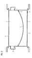
- Fig. 1 shows an air duct system, in which predominantly textiles are used, in longitudinal section.
- Fig. 2 and 3 is the air duct system after Fig. 1 each shown in cross section.
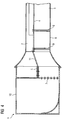
- Fig. 4 shows an air duct system, in which mainly sheets are used, in longitudinal section. Both Fig. 5 and 6 these are supplementary cross sections Fig. 4 ,
- the supply air is blown out by an air conditioning device, not shown here, and should reach the passenger compartment via an air duct system arranged in the roof area of the vehicle.
- this air is first supplied via an air inlet 10 a roof ventilation duct 1 and passed through adjustable flaps 7 in a partial ventilation duct 2 for hot air and / or in a partial ventilation duct 3 for cold air.
- Fig. 1 illustrates the ability to adjust the flaps 7 so that both partial ventilation channels 2 and 3 are supplied with air.
- the flaps 7 are set so that they release the selected partial ventilation duct 3 for cold air and close the not acted on partial ventilation duct 2 for warm air.
- the air duct system after the Fig. 1 . 2 and 3 contains inside a deformable partition 4, which is designed as an airtight textile partition.
- This partition 4 passes through the entire roof ventilation duct 1 and is fixed to a fixed inner partition 5, which can be easily formed from a metal sheet.
- the inner textile partition 4 is attached to the side edges of the roof ventilation duct 1 belonging to the outer channel 6, which may also be formed by textile webs and having air outlets 8.
- a connection of the textile partition 4 with the outer channel 6 can be reached via seams or via crimp connections. It is recommended to provide the outer textile channel 6 and the textile partition 4 with zippers 12, which allow easy access for cleaning purposes. By sewn above the zippers 12 strips they can be protected even from contamination.
- the air pressure and volume flow conditions cause by the resulting pressure difference deformation of the inner textile partition 4, whereby the cross section of a partial ventilation duct 2 or 3 is increased by reducing the other partial ventilation duct 3 and 2 respectively.
- the textile partition 4 is thus deformed in the not acted upon with air partial ventilation duct 2 or 3, as is known from the Fig. 2 and 3 is apparent.
- air duct system has different from the previously described one formed from sheets or other dimensionally stable materials outer channel 6 and an inner partition 4, which is plate-shaped and not deformable.
- This separation 4 may also consist of a metal sheet.
- the sheet metal partition 4 is arranged vertically movable by guides 9 relative to the outer channel 6 and held in its horizontal position. The sealing of the sheet metal separation 4 to the outer channel 6 out z. B. over rubber seals.
- a movable partition 11 made of a deformable material (such as textile, rubber or leather) is fixed on the one hand to the fixed inner partition 5 and on the other hand to the sheet metal partition 4.
- the movable partition 11 thus provides the transition from the fixed inner partition wall 5 to the vertically movable sheet metal partition 4 and follows their movements.
- the sealing of the movable partition 11 to the outer channel 6 is achieved in particular by the inherent rigidity of the movable partition 11, which prevents its deformation.
- support 11 rods made of metal or plastic can be inserted into the separation.
- the sheet metal separation 4 is about the pressure conditions and the volume flow conditions between the two partial ventilation ducts 2 and 3 in the un-acted part-ventilation duct moved and thus increases the cross section of the air-loaded part-ventilation duct, as shown in the Fig. 5 and 6 is shown.
Landscapes
- Engineering & Computer Science (AREA)
- Mechanical Engineering (AREA)
- Physics & Mathematics (AREA)
- Thermal Sciences (AREA)
- Duct Arrangements (AREA)
- Air-Conditioning For Vehicles (AREA)
- Vehicle Waterproofing, Decoration, And Sanitation Devices (AREA)
Abstract
Description
Die Erfindung betrifft ein Luftkanalsystem für Fahrzeuge, insbesondere für Schienenfahrzeuge des Personenverkehrs, mit mindestens einem Dachlüftungskanal, der einen Teil-Lüftungskanal für Warmluft und einen Teil-Lüftungskanal für Kaltluft aufweist.The invention relates to an air duct system for vehicles, in particular for rail vehicles of passenger traffic, with at least one roof ventilation duct, which has a partial ventilation duct for hot air and a partial ventilation duct for cold air.
Ein solches Luftkanalsystem für Fahrzeuge ist beispielsweise aus der
Bei klimatisierten Schienenfahrzeugen mit im Dachbereich montierten Klimaanlagen sind Vorrichtungen zur Luftverteilung allgemein bekannt. Bei diesen Vorrichtungen wird die behandelte Luft von der häufig auf dem Dach des Fahrzeuges angeordneten Klimaanlage mit Hilfe von Zuluftkanälen zu den Hauptlüftungskanälen geleitet, die sich zwischen dem Dach und der Innendecke des Fahrzeuges befinden. Diese Zuluftkanäle führen von den Luftauslässen des Klimagerätes zu Öffnungen, die sich in den Hauptluftkanälen befinden. Wegen der stets begrenzten Außen- und Innenmaße des Fahrzeuges ist der Raum zwischen der Unterseite des Klimagerätes, an der sich die Luftauslässe befinden, und der Oberseiten der Hauptlüftungskanäle sehr gering. Dieser geringe Raum hat zur Folge, dass die Querschnitte der Zuluftkanäle begrenzt sind und sich dadurch in der Regel hohe Strömungsgeschwindigkeiten der Luft ergeben, die wiederum eine starke Geräuschentwicklung bewirken. Dies betrifft Fahrzeuge, bei denen die Heizleistung aus dem als Aufdachgerät konzipierten Klimagerät über mindestens einen abgeteilten, längs im Dachbereich verlaufenden Kanal in den Fahrgastraum eingeführt wird. Der Heizluftkanal ist damit vom Kaltluftkanal abgetrennt. Für verschiedene Klimazonen sind unterschiedliche Volumenströme für Heizluft und Kühlluft notwendig. Dies ist für ein Fahrzeug problematisch, das in verschiedenen Klimaabereichen betrieben werden soll, da sich in bestimmten Klimazonen noch höhere Luftgeschwindigkeiten einstellen würden.In air-conditioned rail vehicles with air conditioning units mounted in the roof area, air distribution devices are well known. In these devices, the treated air from the often arranged on the roof of the vehicle air conditioning using supply air ducts directed to the main ventilation ducts, which are located between the roof and the inner roof of the vehicle. These supply air ducts lead from the air outlets of the air conditioner to openings located in the main air ducts. Because of the ever-limited exterior and interior dimensions of the vehicle, the space between the underside of the air conditioner, where the air outlets are located, and the tops of the main ventilation ducts is very small. This small space has to As a consequence, the cross sections of the supply air ducts are limited and, as a result, high air flow velocities are usually the result, which in turn cause a strong noise development. This concerns vehicles in which the heating power from the air conditioning unit designed as a rooftop unit is introduced into the passenger compartment via at least one compartmentalized channel extending longitudinally in the roof area. The Heizluftkanal is thus separated from the cold air duct. For different climatic zones, different volume flows are required for heating air and cooling air. This is problematic for a vehicle operating in different climates as even higher air velocities would occur in certain climates.
Die Druckschrift
Der Erfindung liegt die Aufgabe zugrunde, die aufgezeigten Nachteile des Standes der Technik zu beseitigen, also insbesondere ein Luftkanalsystem auf möglichst einfache Weise zu schaffen, welches bei Aufteilung des Dachluftkanals in getrennte Querschnitte für Warmluft und Kaltluft zu optimalen Strömungsgeschwindigkeiten für variable Volumenströme der Warm- und Kaltluft bei geringer Geräuschentwicklung führt. Dabei soll der Platzbedarf des Luftkanalsystems im Hinblick auf die bei Fahrzeugen stets knappen Einbauräume möglichst gering sein.The invention has for its object to overcome the disadvantages of the prior art, ie in particular to create an air duct system in the simplest possible way, which in the distribution of the roof air duct in separate sections for hot air and cold air to optimal flow rates for variable flow rates of hot and Cold air leads with low noise. In this case, the space requirement of the air duct system should be as low as possible in view of the always tight in vehicles installation space.
Diese Aufgabe wird erfindungsgemäß durch ein Luftkanalsystem mit den Kennzeichenmerkmalen des Patentanspruchs 1 gelöst. Nach dem Prinzip der Erfindung sind der Teil-Luftkanal für Warmluft und der Teil-Luftkanal für Kaltluft variabel voneinander getrennt. Die dazu vorgesehene entweder verformbar ausgebildete oder bewegbar gehaltene Abtrennung vergrößert durch die Luftdruck- und Volumenstromverhältnisse des beaufschlagten Teil-Luftkanals den vorhandenen Querschnitt dieses beaufschlagten Kanals durch Eindrücken in den nicht beaufschlagten Teil-Luftkanal. Dies geschieht ohne zusätzliche Hilfsenergie.This object is achieved by an air duct system with the license plate features of claim 1. According to the principle of the invention, the partial air duct for hot air and the partial air duct for cold air are variably separated from each other. The purpose intended either deformable formed or movably held partition increased by the air pressure and flow conditions of the acted upon part-air duct the existing Cross section of this acted channel by pressing in the unaffected part-air duct. This happens without additional auxiliary energy.
Die Vorteile der Erfindung liegen insbesondere darin, dass der Querschnitt des beaufschlagten Teil-Luftkanals sozusagen automatisch und ohne Zuführung von Hilfsenergie vergrößert wird. Dadurch sinken die Strömungsgeschwindigkeit und die Geräuschentwicklung. Somit ist es beispielsweise möglich, den gleichen Kanalquerschnitt bei Fahrzeugen für verschiedene Klimazonen einzusetzen, für die an sich größere Querschnitte der Kanäle für Warmluft und Kaltluft notwendig wären oder aber größere Strömungsgeschwindigkeiten und stärkere Geräuschentwicklungen hingenommen werden müssten. Dadurch sinken die Kosten für Konstruktion, Montage und Logistik, wobei überdies alle Anforderungen von Kunden flexibel erfüllt werden können.The advantages of the invention are, in particular, that the cross-section of the acted upon partial air channel is enlarged so to speak automatically and without supply of auxiliary energy. This reduces the flow rate and the noise. Thus, it is possible, for example, to use the same channel cross-section in vehicles for different climatic zones, for which in itself larger cross sections of the channels for warm air and cold air would be necessary or larger flow velocities and stronger noise developments would have to be accepted. This reduces the costs of construction, assembly and logistics, and moreover, all customer requirements can be met flexibly.
Vorteilhafte Ausgestaltungen und Weiterbildungen der Erfindung sind in den Unteransprüchen angegeben.Advantageous embodiments and further developments of the invention are specified in the subclaims.
Nachfolgend wird die Erfindung anhand von zwei Ausführungsbeispielen näher beschrieben, die in der Zeichnung jeweils prinzipartig dargestellt sind.The invention will be described in more detail below with reference to two exemplary embodiments, which are shown in principle in the drawing in each case.
Die Zuluft wird von einer hier nicht dargestellten Klimatisierungseinrichtung ausgeblasen und soll über ein im Dachbereich des Fahrzeugs angeordnetes Luftkanalsystem in den Fahrgastraum gelangen. Gemäß
Das Luftkanalsystem nach den
Die Luftdruck- und Volumenstromverhältnisse bewirken durch den entstehenden Druckunterschied eine Verformung der inneren Textil-Abtrennung 4, wodurch der Querschnitt eines Teil-Lüftungskanals 2 oder 3 unter Verkleinerung des anderen Teil-Lüftungskanals 3 bzw. 2 vergrößert wird. Die Textil-Abtrennung 4 wird also in den nicht mit Luft beaufschlagten Teil-Lüftungskanal 2 oder 3 hinein verformt, wie dies aus den
Das in den
Die Blech-Abtrennung 4 wird über die Druckverhältnisse und die Volumenstromverhältnisse zwischen den beiden Teil-Lüftungskanälen 2 und 3 in den nicht beaufschlagten Teil-Lüftungskanal verschoben und vergrößert so den Querschnitt des mit Luft beaufschlagten Teil-Lüftungskanals, wie dies in den
Claims (8)
- Air duct system for vehicles, in particular for rail vehicles for passenger traffic, having at least one roof venting duct (1) which has a component venting duct (2) for warm air, and a component venting duct (3) for cold air, characterized in that a separating means (4) which is arranged inside the roof venting duct (1) is designed so that it can be deformed or is held in a movable fashion in such a way that the cross section of each of the two component venting ducts (2 or 3) can be enlarged by making the respective other component venting duct (3 or 2) smaller, wherein these changes in cross section are brought about solely by the air pressure and volume flow conditions without external energy and that the separating means (4) which is of deformable design is embodied as an airtight textile separating wall.
- Air duct system according to Claim 1, characterized in that the textile separating means (4) is attached to a fixed, inner separating wall (5) of the roof venting duct (1).
- Air duct system according to Claim 1 or 2, characterized in that the textile separating means (4) is connected to an outer duct (6) of the roof venting duct (1), wherein the outer duct (6) is composed of textile webs.
- Air duct system according to Claim 2 or 3, characterized in that the textile separating means (4) and/or the outer textile duct (6) each contain at least one zip fastener (12).
- Air duct system according to Claim 1, characterized in that the separating means (4) which is held in a movable fashion is of plate shaped design and cannot deform.
- Air duct system according to Claim 5, characterized in that the plate shaped separating means (4) is composed of a piece of sheet metal.
- Air duct system according to Claim 5 or 6, characterized in that the plate shaped separating means (4) is arranged so as to be vertically movable with respect to an outer duct (6) of the roof venting duct (1) by means of guides (9) and is held in its horizontal position, wherein the outer duct (6) is formed from pieces of sheet metal or other dimensionally stable materials.
- Air duct system according to one of Claims 5 to 7, characterized in that the plate shaped separating means (4) is connected to a movable separating means (11) made of deformable material, wherein this movable separating means (11) is attached to a fixed inner separating wall (5) of the roof venting duct (1).
Applications Claiming Priority (2)
| Application Number | Priority Date | Filing Date | Title |
|---|---|---|---|
| DE102005031912A DE102005031912A1 (en) | 2005-07-07 | 2005-07-07 | Air duct system for vehicles, in particular for passenger rail vehicles |
| PCT/EP2006/063129 WO2007006616A1 (en) | 2005-07-07 | 2006-06-13 | Air duct system for vehicles, in particular for rail vehicles for passenger traffic |
Publications (3)
| Publication Number | Publication Date |
|---|---|
| EP1899207A1 EP1899207A1 (en) | 2008-03-19 |
| EP1899207B1 true EP1899207B1 (en) | 2009-10-21 |
| EP1899207B2 EP1899207B2 (en) | 2015-01-21 |
Family
ID=36754068
Family Applications (1)
| Application Number | Title | Priority Date | Filing Date |
|---|---|---|---|
| EP06763659.7A Not-in-force EP1899207B2 (en) | 2005-07-07 | 2006-06-13 | Air duct system for vehicles, in particular for rail vehicles for passenger traffic |
Country Status (9)
| Country | Link |
|---|---|
| US (1) | US8764526B2 (en) |
| EP (1) | EP1899207B2 (en) |
| CN (1) | CN101218140B (en) |
| AT (1) | ATE446232T1 (en) |
| CA (1) | CA2614256C (en) |
| DE (2) | DE102005031912A1 (en) |
| ES (1) | ES2332533T5 (en) |
| RU (1) | RU2380253C2 (en) |
| WO (1) | WO2007006616A1 (en) |
Families Citing this family (17)
| Publication number | Priority date | Publication date | Assignee | Title |
|---|---|---|---|---|
| US9008844B2 (en) * | 2008-06-09 | 2015-04-14 | International Business Machines Corporation | System and method to route airflow using dynamically changing ducts |
| CN102180179A (en) * | 2011-03-31 | 2011-09-14 | 青岛理工大学 | External variable cross-section uniform air supply system for high-speed train |
| DE102011007670A1 (en) * | 2011-04-19 | 2012-10-25 | Siemens Aktiengesellschaft | Luftverteilerbox |
| DE102011075981A1 (en) | 2011-05-17 | 2012-11-22 | Siemens Ag | Vehicle with textile channel |
| DE102012204687A1 (en) * | 2012-03-23 | 2013-09-26 | Siemens Aktiengesellschaft | Rail vehicle with air conditioning duct in the roof area and method for building a roof area of a rail vehicle |
| DE102012207795C5 (en) | 2012-05-10 | 2024-08-22 | Siemens Mobility GmbH | Air duct system for guiding warm air and cold air, especially for a rail vehicle |
| DE102012212466A1 (en) | 2012-07-17 | 2014-01-23 | Siemens Aktiengesellschaft | Air duct system for a passenger rail vehicle |
| DE102013203375A1 (en) * | 2013-02-28 | 2014-08-28 | Siemens Aktiengesellschaft | Air conditioning arrangement for a rail vehicle |
| DE102013218921A1 (en) | 2013-09-20 | 2015-03-26 | Siemens Aktiengesellschaft | Ventilation duct and vehicle with appropriate ventilation duct |
| DE102014215207A1 (en) * | 2014-08-01 | 2016-02-04 | Siemens Aktiengesellschaft | Vehicle, in particular rail vehicle, with an air conditioning device |
| WO2020044536A1 (en) * | 2018-08-31 | 2020-03-05 | 川崎重工業株式会社 | Air-conditioning duct for railroad vehicles |
| CN109109881B (en) * | 2018-09-06 | 2020-08-11 | 中车青岛四方机车车辆股份有限公司 | Side wall assembly of rail vehicle and rail vehicle |
| CN109131392B (en) * | 2018-09-06 | 2020-08-11 | 中车青岛四方机车车辆股份有限公司 | Side wall assembly of rail vehicle and rail vehicle |
| CN110194192A (en) * | 2019-06-12 | 2019-09-03 | 中车长春轨道客车股份有限公司 | A kind of included sound attenuator rail vehicle air conditioner group |
| CN111559398B (en) * | 2020-05-20 | 2021-06-22 | 安徽浦进轨道装备有限公司 | Noise elimination structure of air supply duct of railway vehicle |
| CN112172459B (en) * | 2020-10-20 | 2022-03-01 | 合肥威智机电工程有限公司 | Swinging radian heating ventilation air conditioner air duct |
| DE102022113322A1 (en) | 2022-05-25 | 2023-11-30 | Bayerische Motoren Werke Aktiengesellschaft | Air duct and motor vehicle with such an air duct |
Family Cites Families (15)
| Publication number | Priority date | Publication date | Assignee | Title |
|---|---|---|---|---|
| CH604066A5 (en) | 1976-09-28 | 1978-08-31 | Imre Molnar | Twin channel air conditioning duct |
| DE7820323U1 (en) * | 1978-07-06 | 1978-10-19 | Gebrueder Trox Gmbh, 4133 Neukirchen- Vluyn | CEILING OUTLET FOR AIR CONDITIONING |
| JPH01172010A (en) * | 1987-12-26 | 1989-07-06 | Kojima Press Co Ltd | Duct device |
| US5111739A (en) * | 1989-11-13 | 1992-05-12 | Hall James F | Air flow control system |
| US5399121A (en) * | 1994-02-28 | 1995-03-21 | General Motors Corporation | Vehicle air distribution system with improved space utilization |
| AU669295B2 (en) * | 1994-07-12 | 1996-05-30 | Fiat Ferroviaria Spa | Air conditioning duct for railway vehicles |
| JPH09175148A (en) * | 1995-12-21 | 1997-07-08 | Zexel Corp | Mix damper device of air conditioner for vehicle |
| DE19654633C1 (en) * | 1996-12-28 | 1998-04-02 | Deutsche Waggonbau Ag | Heating/ventilation system for passenger areas in railway carriages for local traffic |
| DE10149594B4 (en) | 2001-10-08 | 2005-09-15 | Bombardier Transportation Gmbh | Ventilation system for vehicles |
| DE20206520U1 (en) | 2002-04-25 | 2002-09-19 | Geiger, Robert, 89335 Ichenhausen | Device for forming a flexible connection |
| JP2003326943A (en) | 2002-05-13 | 2003-11-19 | Toyota Auto Body Co Ltd | Vehicular air conditioning air duct structure |
| DE10251760A1 (en) * | 2002-11-05 | 2004-05-19 | Behr Gmbh & Co. | Air distribution device for distributing air in a motor vehicle's interior has a ventilating element for generating an air current linked to a flow channel and outlets leading into the interior |
| FR2852271B1 (en) * | 2003-03-13 | 2006-07-28 | Valeo Climatisation | DEVICE FOR HEATING-VENTILATION AND / OR AIR CONDITIONING OF COMPACT STRUCTURE FOR THE HABITACLE OF A MOTOR VEHICLE |
| JP3728601B2 (en) * | 2003-06-18 | 2005-12-21 | 日本航空電子工業株式会社 | Card connector |
| DE102004028784A1 (en) * | 2004-06-16 | 2006-01-05 | Behr Gmbh & Co. Kg | Device for supplying air to an interior of a vehicle |
-
2005
- 2005-07-07 DE DE102005031912A patent/DE102005031912A1/en not_active Withdrawn
-
2006
- 2006-06-13 CN CN2006800246861A patent/CN101218140B/en not_active Expired - Fee Related
- 2006-06-13 CA CA2614256A patent/CA2614256C/en not_active Expired - Fee Related
- 2006-06-13 DE DE502006005201T patent/DE502006005201D1/en active Active
- 2006-06-13 ES ES06763659.7T patent/ES2332533T5/en active Active
- 2006-06-13 EP EP06763659.7A patent/EP1899207B2/en not_active Not-in-force
- 2006-06-13 RU RU2008104639/11A patent/RU2380253C2/en not_active IP Right Cessation
- 2006-06-13 WO PCT/EP2006/063129 patent/WO2007006616A1/en active Application Filing
- 2006-06-13 US US11/988,325 patent/US8764526B2/en not_active Expired - Fee Related
- 2006-06-13 AT AT06763659T patent/ATE446232T1/en active
Also Published As
| Publication number | Publication date |
|---|---|
| WO2007006616A1 (en) | 2007-01-18 |
| US20090130967A1 (en) | 2009-05-21 |
| CA2614256A1 (en) | 2007-01-18 |
| CN101218140A (en) | 2008-07-09 |
| CA2614256C (en) | 2011-04-05 |
| CN101218140B (en) | 2010-05-19 |
| DE102005031912A1 (en) | 2007-01-11 |
| RU2008104639A (en) | 2009-08-20 |
| US8764526B2 (en) | 2014-07-01 |
| DE502006005201D1 (en) | 2009-12-03 |
| EP1899207A1 (en) | 2008-03-19 |
| ATE446232T1 (en) | 2009-11-15 |
| RU2380253C2 (en) | 2010-01-27 |
| ES2332533T5 (en) | 2015-02-26 |
| ES2332533T3 (en) | 2010-02-08 |
| EP1899207B2 (en) | 2015-01-21 |
Similar Documents
| Publication | Publication Date | Title |
|---|---|---|
| EP1899207B1 (en) | Air duct system for vehicles, in particular for rail vehicles for passenger traffic | |
| DE102019203839B4 (en) | Ventilation arrangement and method for ventilating a motor vehicle | |
| EP3737599B1 (en) | Vehicle having an air conditioning assembly | |
| DE112019002360T5 (en) | Blower | |
| DE102009044760B4 (en) | Air conditioning for a motor vehicle | |
| EP1957299B1 (en) | Device for connecting air ducts, motor vehicle door, motor vehicle pillar and motor vehicle inner lining part | |
| DE10219053A1 (en) | aerator | |
| DE102017006090B4 (en) | Air guiding device for a vehicle | |
| DE102019119564A1 (en) | AIR CONDITIONED AIR DISTRIBUTION SYSTEM FOR A VEHICLE | |
| DE10256619B3 (en) | Air conditioner for vehicles | |
| DE102019206851A1 (en) | Air conditioning device for a motor vehicle, motor vehicle | |
| DE102008016238A1 (en) | Air nozzle for supplying air into inner area of vehicle i.e. motor vehicle, has ventilation flap that is positioned opposite to flow direction of air in position of flap partially based on axis of rotation | |
| DE602004005988T2 (en) | Carrier structure for the dashboard of a motor vehicle | |
| DE10349574A1 (en) | Ceiling air duct system for automotive air conditioning systems | |
| DE102008030063A1 (en) | air conditioning | |
| DE102005003346A1 (en) | Vehicle air conditioning system, has check valve arrangement to permit hot air flow from hot air duct into mixing region and prevent penetration of cold air or mixed air into duct and including valves partially made up of flexible material | |
| DE102007013432A1 (en) | Hot air channel for air conditioning system of motor vehicle, has separating web, where hot air leaving channel is divided into two hot air partial flows such that each flow supplies hot air to respective air outlets of system | |
| DE102011015859A1 (en) | Self-supporting cooling module | |
| DE10350193A1 (en) | Vehicle climate control system, has foot room channel with wall separated from outside of spiral casing by insulation space | |
| EP1843908B1 (en) | Motor vehicle air conditioning system | |
| EP3180223B1 (en) | Rail vehicle having an air-conditioning system | |
| WO2005084973A1 (en) | Air-conditioning device, in particular for a motor vehicle | |
| DE20204970U1 (en) | Air passage | |
| DE102009023986A1 (en) | Intervention structure of an air conditioner housing | |
| EP2017102A2 (en) | Air conditioning unit with a lower sump as a roof cladding segment |
Legal Events
| Date | Code | Title | Description |
|---|---|---|---|
| PUAI | Public reference made under article 153(3) epc to a published international application that has entered the european phase |
Free format text: ORIGINAL CODE: 0009012 |
|
| 17P | Request for examination filed |
Effective date: 20071205 |
|
| AK | Designated contracting states |
Kind code of ref document: A1 Designated state(s): AT BE BG CH CY CZ DE DK EE ES FI FR GB GR HU IE IS IT LI LT LU LV MC NL PL PT RO SE SI SK TR |
|
| DAX | Request for extension of the european patent (deleted) | ||
| RIN1 | Information on inventor provided before grant (corrected) |
Inventor name: HOEFLER, WERNER Inventor name: WICHMANN, RAINER |
|
| GRAP | Despatch of communication of intention to grant a patent |
Free format text: ORIGINAL CODE: EPIDOSNIGR1 |
|
| DAX | Request for extension of the european patent (deleted) | ||
| GRAS | Grant fee paid |
Free format text: ORIGINAL CODE: EPIDOSNIGR3 |
|
| GRAA | (expected) grant |
Free format text: ORIGINAL CODE: 0009210 |
|
| AK | Designated contracting states |
Kind code of ref document: B1 Designated state(s): AT BE BG CH CY CZ DE DK EE ES FI FR GB GR HU IE IS IT LI LT LU LV MC NL PL PT RO SE SI SK TR |
|
| REG | Reference to a national code |
Ref country code: GB Ref legal event code: FG4D Free format text: NOT ENGLISH |
|
| REG | Reference to a national code |
Ref country code: CH Ref legal event code: NV Representative=s name: SIEMENS SCHWEIZ AG Ref country code: CH Ref legal event code: EP |
|
| REG | Reference to a national code |
Ref country code: IE Ref legal event code: FG4D |
|
| REF | Corresponds to: |
Ref document number: 502006005201 Country of ref document: DE Date of ref document: 20091203 Kind code of ref document: P |
|
| REG | Reference to a national code |
Ref country code: SE Ref legal event code: TRGR |
|
| REG | Reference to a national code |
Ref country code: ES Ref legal event code: FG2A Ref document number: 2332533 Country of ref document: ES Kind code of ref document: T3 |
|
| LTIE | Lt: invalidation of european patent or patent extension |
Effective date: 20091021 |
|
| PG25 | Lapsed in a contracting state [announced via postgrant information from national office to epo] |
Ref country code: PT Free format text: LAPSE BECAUSE OF FAILURE TO SUBMIT A TRANSLATION OF THE DESCRIPTION OR TO PAY THE FEE WITHIN THE PRESCRIBED TIME-LIMIT Effective date: 20100222 Ref country code: IS Free format text: LAPSE BECAUSE OF FAILURE TO SUBMIT A TRANSLATION OF THE DESCRIPTION OR TO PAY THE FEE WITHIN THE PRESCRIBED TIME-LIMIT Effective date: 20100221 Ref country code: FI Free format text: LAPSE BECAUSE OF FAILURE TO SUBMIT A TRANSLATION OF THE DESCRIPTION OR TO PAY THE FEE WITHIN THE PRESCRIBED TIME-LIMIT Effective date: 20091021 Ref country code: LT Free format text: LAPSE BECAUSE OF FAILURE TO SUBMIT A TRANSLATION OF THE DESCRIPTION OR TO PAY THE FEE WITHIN THE PRESCRIBED TIME-LIMIT Effective date: 20091021 |
|
| REG | Reference to a national code |
Ref country code: IE Ref legal event code: FD4D |
|
| PG25 | Lapsed in a contracting state [announced via postgrant information from national office to epo] |
Ref country code: CY Free format text: LAPSE BECAUSE OF FAILURE TO SUBMIT A TRANSLATION OF THE DESCRIPTION OR TO PAY THE FEE WITHIN THE PRESCRIBED TIME-LIMIT Effective date: 20091021 Ref country code: SI Free format text: LAPSE BECAUSE OF FAILURE TO SUBMIT A TRANSLATION OF THE DESCRIPTION OR TO PAY THE FEE WITHIN THE PRESCRIBED TIME-LIMIT Effective date: 20091021 Ref country code: LV Free format text: LAPSE BECAUSE OF FAILURE TO SUBMIT A TRANSLATION OF THE DESCRIPTION OR TO PAY THE FEE WITHIN THE PRESCRIBED TIME-LIMIT Effective date: 20091021 Ref country code: PL Free format text: LAPSE BECAUSE OF FAILURE TO SUBMIT A TRANSLATION OF THE DESCRIPTION OR TO PAY THE FEE WITHIN THE PRESCRIBED TIME-LIMIT Effective date: 20091021 |
|
| PLBI | Opposition filed |
Free format text: ORIGINAL CODE: 0009260 |
|
| PG25 | Lapsed in a contracting state [announced via postgrant information from national office to epo] |
Ref country code: EE Free format text: LAPSE BECAUSE OF FAILURE TO SUBMIT A TRANSLATION OF THE DESCRIPTION OR TO PAY THE FEE WITHIN THE PRESCRIBED TIME-LIMIT Effective date: 20091021 Ref country code: DK Free format text: LAPSE BECAUSE OF FAILURE TO SUBMIT A TRANSLATION OF THE DESCRIPTION OR TO PAY THE FEE WITHIN THE PRESCRIBED TIME-LIMIT Effective date: 20091021 Ref country code: IE Free format text: LAPSE BECAUSE OF FAILURE TO SUBMIT A TRANSLATION OF THE DESCRIPTION OR TO PAY THE FEE WITHIN THE PRESCRIBED TIME-LIMIT Effective date: 20091021 Ref country code: BG Free format text: LAPSE BECAUSE OF FAILURE TO SUBMIT A TRANSLATION OF THE DESCRIPTION OR TO PAY THE FEE WITHIN THE PRESCRIBED TIME-LIMIT Effective date: 20100121 Ref country code: RO Free format text: LAPSE BECAUSE OF FAILURE TO SUBMIT A TRANSLATION OF THE DESCRIPTION OR TO PAY THE FEE WITHIN THE PRESCRIBED TIME-LIMIT Effective date: 20091021 |
|
| 26 | Opposition filed |
Opponent name: BOMBARDIER TRANSPORTATION GMBH Effective date: 20100721 |
|
| PG25 | Lapsed in a contracting state [announced via postgrant information from national office to epo] |
Ref country code: SK Free format text: LAPSE BECAUSE OF FAILURE TO SUBMIT A TRANSLATION OF THE DESCRIPTION OR TO PAY THE FEE WITHIN THE PRESCRIBED TIME-LIMIT Effective date: 20091021 |
|
| PGFP | Annual fee paid to national office [announced via postgrant information from national office to epo] |
Ref country code: CZ Payment date: 20100611 Year of fee payment: 5 |
|
| PLAX | Notice of opposition and request to file observation + time limit sent |
Free format text: ORIGINAL CODE: EPIDOSNOBS2 |
|
| PG25 | Lapsed in a contracting state [announced via postgrant information from national office to epo] |
Ref country code: GR Free format text: LAPSE BECAUSE OF FAILURE TO SUBMIT A TRANSLATION OF THE DESCRIPTION OR TO PAY THE FEE WITHIN THE PRESCRIBED TIME-LIMIT Effective date: 20100122 |
|
| PLBB | Reply of patent proprietor to notice(s) of opposition received |
Free format text: ORIGINAL CODE: EPIDOSNOBS3 |
|
| PG25 | Lapsed in a contracting state [announced via postgrant information from national office to epo] |
Ref country code: MC Free format text: LAPSE BECAUSE OF NON-PAYMENT OF DUE FEES Effective date: 20100630 |
|
| RDAF | Communication despatched that patent is revoked |
Free format text: ORIGINAL CODE: EPIDOSNREV1 |
|
| PG25 | Lapsed in a contracting state [announced via postgrant information from national office to epo] |
Ref country code: CZ Free format text: LAPSE BECAUSE OF NON-PAYMENT OF DUE FEES Effective date: 20110613 |
|
| APBM | Appeal reference recorded |
Free format text: ORIGINAL CODE: EPIDOSNREFNO |
|
| APBP | Date of receipt of notice of appeal recorded |
Free format text: ORIGINAL CODE: EPIDOSNNOA2O |
|
| APAH | Appeal reference modified |
Free format text: ORIGINAL CODE: EPIDOSCREFNO |
|
| APBQ | Date of receipt of statement of grounds of appeal recorded |
Free format text: ORIGINAL CODE: EPIDOSNNOA3O |
|
| PG25 | Lapsed in a contracting state [announced via postgrant information from national office to epo] |
Ref country code: LU Free format text: LAPSE BECAUSE OF NON-PAYMENT OF DUE FEES Effective date: 20100613 Ref country code: HU Free format text: LAPSE BECAUSE OF FAILURE TO SUBMIT A TRANSLATION OF THE DESCRIPTION OR TO PAY THE FEE WITHIN THE PRESCRIBED TIME-LIMIT Effective date: 20100422 |
|
| PG25 | Lapsed in a contracting state [announced via postgrant information from national office to epo] |
Ref country code: TR Free format text: LAPSE BECAUSE OF FAILURE TO SUBMIT A TRANSLATION OF THE DESCRIPTION OR TO PAY THE FEE WITHIN THE PRESCRIBED TIME-LIMIT Effective date: 20091021 |
|
| RAP2 | Party data changed (patent owner data changed or rights of a patent transferred) |
Owner name: SIEMENS AKTIENGESELLSCHAFT |
|
| APBU | Appeal procedure closed |
Free format text: ORIGINAL CODE: EPIDOSNNOA9O |
|
| PLAY | Examination report in opposition despatched + time limit |
Free format text: ORIGINAL CODE: EPIDOSNORE2 |
|
| PLAH | Information related to despatch of examination report in opposition + time limit modified |
Free format text: ORIGINAL CODE: EPIDOSCORE2 |
|
| PLBC | Reply to examination report in opposition received |
Free format text: ORIGINAL CODE: EPIDOSNORE3 |
|
| PG25 | Lapsed in a contracting state [announced via postgrant information from national office to epo] |
Ref country code: IT Free format text: LAPSE BECAUSE OF NON-PAYMENT OF DUE FEES Effective date: 20130613 |
|
| PGFP | Annual fee paid to national office [announced via postgrant information from national office to epo] |
Ref country code: NL Payment date: 20140603 Year of fee payment: 9 Ref country code: SE Payment date: 20140605 Year of fee payment: 9 |
|
| PUAH | Patent maintained in amended form |
Free format text: ORIGINAL CODE: 0009272 |
|
| STAA | Information on the status of an ep patent application or granted ep patent |
Free format text: STATUS: PATENT MAINTAINED AS AMENDED |
|
| 27A | Patent maintained in amended form |
Effective date: 20150121 |
|
| AK | Designated contracting states |
Kind code of ref document: B2 Designated state(s): AT BE BG CH CY CZ DE DK EE ES FI FR GB GR HU IE IS IT LI LT LU LV MC NL PL PT RO SE SI SK TR |
|
| REG | Reference to a national code |
Ref country code: DE Ref legal event code: R102 Ref document number: 502006005201 Country of ref document: DE |
|
| REG | Reference to a national code |
Ref country code: CH Ref legal event code: AELC |
|
| REG | Reference to a national code |
Ref country code: ES Ref legal event code: DC2A Ref document number: 2332533 Country of ref document: ES Kind code of ref document: T5 Effective date: 20150226 Ref country code: DE Ref legal event code: R102 Ref document number: 502006005201 Country of ref document: DE Effective date: 20150121 |
|
| REG | Reference to a national code |
Ref country code: SE Ref legal event code: RPEO |
|
| REG | Reference to a national code |
Ref country code: NL Ref legal event code: T3 |
|
| PG25 | Lapsed in a contracting state [announced via postgrant information from national office to epo] |
Ref country code: LV Free format text: LAPSE BECAUSE OF FAILURE TO SUBMIT A TRANSLATION OF THE DESCRIPTION OR TO PAY THE FEE WITHIN THE PRESCRIBED TIME-LIMIT Effective date: 20150121 |
|
| REG | Reference to a national code |
Ref country code: SE Ref legal event code: EUG |
|
| PG25 | Lapsed in a contracting state [announced via postgrant information from national office to epo] |
Ref country code: SE Free format text: LAPSE BECAUSE OF NON-PAYMENT OF DUE FEES Effective date: 20150614 |
|
| REG | Reference to a national code |
Ref country code: NL Ref legal event code: MM Effective date: 20150701 |
|
| PG25 | Lapsed in a contracting state [announced via postgrant information from national office to epo] |
Ref country code: NL Free format text: LAPSE BECAUSE OF NON-PAYMENT OF DUE FEES Effective date: 20150701 |
|
| REG | Reference to a national code |
Ref country code: FR Ref legal event code: PLFP Year of fee payment: 11 |
|
| REG | Reference to a national code |
Ref country code: FR Ref legal event code: PLFP Year of fee payment: 12 |
|
| PGFP | Annual fee paid to national office [announced via postgrant information from national office to epo] |
Ref country code: AT Payment date: 20170504 Year of fee payment: 12 Ref country code: BE Payment date: 20170620 Year of fee payment: 12 |
|
| REG | Reference to a national code |
Ref country code: CH Ref legal event code: PCOW Free format text: NEW ADDRESS: WERNER-VON-SIEMENS-STRASSE 1, 80333 MUENCHEN (DE) |
|
| REG | Reference to a national code |
Ref country code: FR Ref legal event code: PLFP Year of fee payment: 13 |
|
| PGFP | Annual fee paid to national office [announced via postgrant information from national office to epo] |
Ref country code: IT Payment date: 20180720 Year of fee payment: 11 |
|
| REG | Reference to a national code |
Ref country code: DE Ref legal event code: R081 Ref document number: 502006005201 Country of ref document: DE Owner name: SIEMENS MOBILITY GMBH, DE Free format text: FORMER OWNER: SIEMENS AKTIENGESELLSCHAFT, 80333 MUENCHEN, DE |
|
| REG | Reference to a national code |
Ref country code: CH Ref legal event code: PL |
|
| REG | Reference to a national code |
Ref country code: AT Ref legal event code: MM01 Ref document number: 446232 Country of ref document: AT Kind code of ref document: T Effective date: 20180613 |
|
| REG | Reference to a national code |
Ref country code: GB Ref legal event code: 732E Free format text: REGISTERED BETWEEN 20190207 AND 20190213 Ref country code: BE Ref legal event code: MM Effective date: 20180630 |
|
| PG25 | Lapsed in a contracting state [announced via postgrant information from national office to epo] |
Ref country code: AT Free format text: LAPSE BECAUSE OF NON-PAYMENT OF DUE FEES Effective date: 20180613 Ref country code: LI Free format text: LAPSE BECAUSE OF NON-PAYMENT OF DUE FEES Effective date: 20180630 Ref country code: CH Free format text: LAPSE BECAUSE OF NON-PAYMENT OF DUE FEES Effective date: 20180630 |
|
| PG25 | Lapsed in a contracting state [announced via postgrant information from national office to epo] |
Ref country code: BE Free format text: LAPSE BECAUSE OF NON-PAYMENT OF DUE FEES Effective date: 20180630 |
|
| PGFP | Annual fee paid to national office [announced via postgrant information from national office to epo] |
Ref country code: FR Payment date: 20190619 Year of fee payment: 14 |
|
| PGFP | Annual fee paid to national office [announced via postgrant information from national office to epo] |
Ref country code: GB Payment date: 20190610 Year of fee payment: 14 Ref country code: DE Payment date: 20190819 Year of fee payment: 14 |
|
| REG | Reference to a national code |
Ref country code: ES Ref legal event code: FD2A Effective date: 20201028 |
|
| REG | Reference to a national code |
Ref country code: DE Ref legal event code: R119 Ref document number: 502006005201 Country of ref document: DE |
|
| PG25 | Lapsed in a contracting state [announced via postgrant information from national office to epo] |
Ref country code: ES Free format text: LAPSE BECAUSE OF NON-PAYMENT OF DUE FEES Effective date: 20190614 |
|
| GBPC | Gb: european patent ceased through non-payment of renewal fee |
Effective date: 20200613 |
|
| PG25 | Lapsed in a contracting state [announced via postgrant information from national office to epo] |
Ref country code: FR Free format text: LAPSE BECAUSE OF NON-PAYMENT OF DUE FEES Effective date: 20200630 Ref country code: GB Free format text: LAPSE BECAUSE OF NON-PAYMENT OF DUE FEES Effective date: 20200613 |
|
| PG25 | Lapsed in a contracting state [announced via postgrant information from national office to epo] |
Ref country code: DE Free format text: LAPSE BECAUSE OF NON-PAYMENT OF DUE FEES Effective date: 20210101 |