EP1898435A2 - Switch and contact modules therefor - Google Patents
Switch and contact modules therefor Download PDFInfo
- Publication number
- EP1898435A2 EP1898435A2 EP07115798A EP07115798A EP1898435A2 EP 1898435 A2 EP1898435 A2 EP 1898435A2 EP 07115798 A EP07115798 A EP 07115798A EP 07115798 A EP07115798 A EP 07115798A EP 1898435 A2 EP1898435 A2 EP 1898435A2
- Authority
- EP
- European Patent Office
- Prior art keywords
- contact
- plunger
- pair
- switch
- contact modules
- Prior art date
- Legal status (The legal status is an assumption and is not a legal conclusion. Google has not performed a legal analysis and makes no representation as to the accuracy of the status listed.)
- Granted
Links
Images




Classifications
-
- H—ELECTRICITY
- H01—ELECTRIC ELEMENTS
- H01H—ELECTRIC SWITCHES; RELAYS; SELECTORS; EMERGENCY PROTECTIVE DEVICES
- H01H13/00—Switches having rectilinearly-movable operating part or parts adapted for pushing or pulling in one direction only, e.g. push-button switch
- H01H13/02—Details
- H01H13/12—Movable parts; Contacts mounted thereon
- H01H13/14—Operating parts, e.g. push-button
- H01H13/18—Operating parts, e.g. push-button adapted for actuation at a limit or other predetermined position in the path of a body, the relative movement of switch and body being primarily for a purpose other than the actuation of the switch, e.g. door switch, limit switch, floor-levelling switch of a lift
- H01H13/186—Operating parts, e.g. push-button adapted for actuation at a limit or other predetermined position in the path of a body, the relative movement of switch and body being primarily for a purpose other than the actuation of the switch, e.g. door switch, limit switch, floor-levelling switch of a lift wherein the pushbutton is rectilinearly actuated by a lever pivoting on the housing of the switch
-
- H—ELECTRICITY
- H01—ELECTRIC ELEMENTS
- H01H—ELECTRIC SWITCHES; RELAYS; SELECTORS; EMERGENCY PROTECTIVE DEVICES
- H01H11/00—Apparatus or processes specially adapted for the manufacture of electric switches
- H01H11/0006—Apparatus or processes specially adapted for the manufacture of electric switches for converting electric switches
- H01H11/0018—Apparatus or processes specially adapted for the manufacture of electric switches for converting electric switches for allowing different operating parts
-
- H—ELECTRICITY
- H01—ELECTRIC ELEMENTS
- H01H—ELECTRIC SWITCHES; RELAYS; SELECTORS; EMERGENCY PROTECTIVE DEVICES
- H01H13/00—Switches having rectilinearly-movable operating part or parts adapted for pushing or pulling in one direction only, e.g. push-button switch
- H01H13/50—Switches having rectilinearly-movable operating part or parts adapted for pushing or pulling in one direction only, e.g. push-button switch having a single operating member
- H01H13/503—Stacked switches
-
- H—ELECTRICITY
- H01—ELECTRIC ELEMENTS
- H01H—ELECTRIC SWITCHES; RELAYS; SELECTORS; EMERGENCY PROTECTIVE DEVICES
- H01H15/00—Switches having rectilinearly-movable operating part or parts adapted for actuation in opposite directions, e.g. slide switch
- H01H15/02—Details
- H01H15/06—Movable parts; Contacts mounted thereon
- H01H15/10—Operating parts
- H01H15/102—Operating parts comprising cam devices
- H01H15/107—Operating parts comprising cam devices actuating conventional selfcontained microswitches
-
- H—ELECTRICITY
- H01—ELECTRIC ELEMENTS
- H01H—ELECTRIC SWITCHES; RELAYS; SELECTORS; EMERGENCY PROTECTIVE DEVICES
- H01H11/00—Apparatus or processes specially adapted for the manufacture of electric switches
- H01H11/0006—Apparatus or processes specially adapted for the manufacture of electric switches for converting electric switches
-
- H—ELECTRICITY
- H01—ELECTRIC ELEMENTS
- H01H—ELECTRIC SWITCHES; RELAYS; SELECTORS; EMERGENCY PROTECTIVE DEVICES
- H01H11/00—Apparatus or processes specially adapted for the manufacture of electric switches
- H01H11/0006—Apparatus or processes specially adapted for the manufacture of electric switches for converting electric switches
- H01H11/0018—Apparatus or processes specially adapted for the manufacture of electric switches for converting electric switches for allowing different operating parts
- H01H2011/0025—Apparatus or processes specially adapted for the manufacture of electric switches for converting electric switches for allowing different operating parts with provisions for allowing different orientation of the operating part, e.g. turning knob can be mounted in different positions
-
- H—ELECTRICITY
- H01—ELECTRIC ELEMENTS
- H01H—ELECTRIC SWITCHES; RELAYS; SELECTORS; EMERGENCY PROTECTIVE DEVICES
- H01H3/00—Mechanisms for operating contacts
- H01H3/32—Driving mechanisms, i.e. for transmitting driving force to the contacts
- H01H3/46—Driving mechanisms, i.e. for transmitting driving force to the contacts using rod or lever linkage, e.g. toggle
Definitions
- This invention relates to a switch and contact modules therefor.
- Japanese Patent Publication Tokkai 2003-45294 describes a switch case incorporating a switching mechanism having a mobile plunger biased by a spring and provided with a plurality of mobile pieces corresponding to a plurality of fixed terminals such that the contacts for a plurality of circuits can be opened and closed as the plunger is moved.
- Switches according to this invention are characterized by comprising contact modules including either normally open or closed contact mechanisms in a module case and providing contact modules with the same type of contact mechanisms and a single actuator for undergoing a seesaw-like rotary motion within a switch case such that the end parts of the actuator operate the contact modules.
- a switch provided with contacts of normally open and/or normally closed type can be structured by incorporating in a switch case contact modules and an actuator which have been prepared in advance. Since the contact module corresponding to one of the end parts of the actuator which is caused to undergo a seesaw-like rotary motion serves as a normally open contact and the contact module corresponding to the other end part serves as a normally closed contact, a switch with any specified numbers of normally open and closed contacts can be obtained.
- a plurality of such contact modules may be arranged along the supporting axis of the actuator according to a preferred embodiment of the invention.
- three contact modules may be arranged in the direction of the supporting axis of the actuator, two of the contact modules being placed corresponding to one of the two end parts of the actuator and the remaining one contact module being placed corresponding to the other end part of the actuator such that a switch with two normally open contact points and one normally closed contact point may be obtained.
- a plurality of contact modules may be arranged in a same orientation along the supporting axis so as to have the operating parts of their plungers at different positions on both sides of the supporting axis.
- contact modules of two different kinds having operating parts at different positions may be preliminarily prepared such that specified numbers of them are arranged all in a same orientation along the supporting axis of the actuator.
- a plurality of such contact modules may be arranged so as to have operating parts of the plungers at positions displaced from center of the module case on both sides of the supporting axis, specified ones of the contact modules being arranged in a reversed orientation along the supporting axis.
- a subset of said contact modules may be arranged along said supporting axis in a first orientation with respect to the supporting axis and another subset of said contact modules may be arranged in a second orientation that is reversed with respect to the first orientation.
- “reversed orientation” may mean an orientation in which the contact module is rotated by 180° around a rotation axis that may be perpendicular to the supporting axis.
- each of the operating parts of a plurality of contact modules can be distributed to both sides of the supporting axis of the actuator merely by arranging a specified number of contact modules in a reversed orientation in the direction of the supporting axis of the actuator.
- each of the contact modules includes a normally closed contact mechanism.
- the contact modules include a normally open contact mechanism, the mobile piece is biased so as to separate from the pair of fixed terminals and to be connected to them by moving the plunger against the biasing force of the spring. In such a case, the mobile piece would be supported so as to be able to be elastically retracted such that the stroke of the plunger can be absorbed after the mobile piece contacts the fixed terminals.
- the contact modules are formed to incorporate a normally closed contact mechanism, on the other hand, the mobile piece is normally in contact with the pair of fixed terminals, being fastened to the plunger and adapted to be separated from the fixed terminals as the plunger is pressed by means of a spring.
- the mobile piece would have to be provided to the plunger so as to be displaceable with respect thereto and a back-up spring would be necessary for biasing in the case of a normally open mechanism but the mobile piece may be fastened to the plunger in the case of a normally closed mechanism.
- the number of components can be reduced and the production cost can be lowered in the latter case.
- a contact module of this invention comprises a normally open or normally closed contact mechanism having a pair of fixed terminals with fixed contact points and a mobile piece with a pair of mobile contact points corresponding to these fixed terminals, a plunger having an operating part for moving the mobile piece and a module case incorporating the contact mechanism and the plunger, wherein the operating part of the plunger is eccentrically positioned with respect to the module case.
- Two groups of such contact modules may be formed by arranging specified numbers of normally oriented contact modules and oppositely oriented contact modules such that their contact parts of their plungers are separated by a specified distance. If an actuator rotatably supported around an axis is provided such that these two groups of contact parts can be operated by the end parts of this rotatably supported actuator, it is possible to obtain a switch for a plurality of circuits by using the contact modules of one of the groups as normally open contacts and those of the other group as normally closed contacts.
- this invention also relates to a pair of similarly designed contact modules each comprising a normally open or normally closed contact mechanism having a pair of fixed terminals with fixed contact points and a mobile piece with a pair of mobile contact points corresponding to these fixed terminals, a plunger having an operating part for moving the mobile piece and a module case including the contact mechanism and said plunger wherein at least one of the pair of contact modules is a contact module as previously described, and wherein the operating parts of the two contact modules are arranged at mutually different positions with respect to the corresponding module case. In other words, the operating part is positioned differently with respect to the module case between the pair.
- switches for a variety of different circuits can be formed according to this invention by using contact modules of only two kinds that are nearly identically designed except that the position of the operating part of the plunger with respect to the module case is different between the two kinds of the contact modules.
- this invention further relates to a pair of similarly designed contact modules each comprising a normally open or normally closed contact mechanism having a pair of fixed terminals with fixed contact points and a mobile piece with a pair of mobile contact points corresponding to the fixed terminals, a plunger having an operating part for moving the mobile piece, and a module case including the contact mechanism and the plunger wherein the plungers of the pair have the same specifications and the plungers have mutually opposite orientations within the module cases.
- the operating parts of the pair are at shifted positions and mutually oppositely oriented with respect to the corresponding module case.
- “mutually opposite orientations” may refer to orientations that can be rotated into each other through a 180° rotation around a rotation axis.
- plunger having the same specification refers in particular to plungers having the same dimensions. Such plungers having the same specification can be conveniently fabricated using the same process.
- switches for a variety of different circuits can be formed according to this invention by using contact modules of only two kinds that are nearly identically designed except that the operating parts of the plungers of the pair are eccentrically positioned and mutually oppositely oriented with respect to the corresponding module case.
- switches for a variety of circuits for different purposes can be easily and economically formed by incorporating in a switch case contact modules formed nearly identically together with an actuator.
- a pair of contact modules may each comprise:
- a pair of contact modules may each comprise:
- Fig. 1 shows the basic structure of a switch A embodying this invention, incorporating two contact modules M, an actuator 2 adapted to move like a see-saw and a push button 3 for operating the actuator 2 inside a switch case 1.
- the two contact modules M have the same specifications, each having a normally closed contact mechanism 5 arranged inside a module case 4.
- the contact mechanism 5 comprises a mutually facing pair of fixed terminals 6 disposed with a certain interval in between, a mobile piece 7 made of a conductive metal plate disposed in opposition to the end parts of the fixed terminals 6 from below, a plunger 8 affixed to and supported by this mobile piece 7 and a spring 9 for urging the plunger 8 slidingly upward.
- Both fixed terminals 6 protrude downward from the bottom of the module case 4 so as to be connected to an external lead line.
- An operating part 8a extends from the plunger 8 and protrudes upward from the case.
- the actuator 2 is axially supported by the switch case 1 so as to be able to swing like a seesaw around a fulcrum (supporting point) p at a position above and between the two contact modules M.
- the operating parts 8a protruding from the two contact modules M are positioned in opposition to both end parts of the actuator 3.
- the actuator 3 is biased by a spiral spring 10 provided to the fulcrum p so as to swing back in a fixed direction.
- the biasing force of this spiral spring 10 is stronger than the force by the upwardly biasing spring force 9 such that, according to the illustrated example, the plunger 8 is pushed in on the left-hand side of the actuator 3 under the normal condition when the push button 3 is not being operated, such that the contact mechanism 5 of the contact module M on the left-hand side is opened, and the contact mechanism 5 of the contact module M on the right-hand side is closed with the plunger 8 being moved upward by the biasing force.
- the actuator 3 is moved in the clockwise direction in the figure against the spring 9 in the contact module M on the right-hand side such that the contact mechanism 5 of the contact module M on the left-hand side is closed and the contact mechanism 5 of the contact module M on the right-hand side is opened.
- the switch A for oppositely opening and closing two circuits is thus structured by using two contact modules M having the same specification with a normally closed contact.
- a switch capable of opening and closing three or more circuits can be obtained.
- Fig. 2 is a front view of a specific example of the contact module M
- Fig. 3 is a oblique view of two contact modules M arranged in parallel.
- the operating part 8a of the plunger 8 incorporated in this contact module M is at a position removed towards the back edge, and is protruding at a position removed backward from the center of the case.
- Figs. 4 and 5 show a switch A for two circuits incorporating two contact modules M thus arranged next to each other in opposite orientations.
- the actuator 2 incorporated inside the switch case 1 of this switch A has a larger width, the axial direction of its fulcrum p being the direction in which the contact modules M are arranged in parallel.
- the distal end (behind the paper plane) of the actuator 2 faces the operating part 8a of the contact module M on the right-hand side and the proximal end of the actuator 2 faces the operating part 8a of the contact module M on the left-hand side.
- the actuator 2 is caused to pivot backward by the strong spiral spring 10
- the contact mechanism 5 of the contact module M on the right-hand side is opened if the push button 3 is not being pressed, and the contact mechanism 5 of the contact module M on the left-hand side is closed.
- Figs. 6A, 6B and 6C (together referred to as Fig. 6) and Figs. 7A, 7B and 7C (together referred to as Fig. 7) show examples of contact module M(1) and M(2).
- Figs. 6A and 7A are oblique views of the entire contact modules M(1) and M(2)
- Figs. 6B and 7B are oblique views of their plungers 8(1) and 8(2)
- Figs, 6C and 7C are their sectional side views.
- the contact mechanisms 5 incorporated in these contact modules M(1) and M(2) are also formed to be normally closed, having a mobile piece 7 biased to be in contact with a pair of fixed terminals 6. All of their components other than the plunger 8 are the same between the two contact modules M(1) and M(2).
- the plunger 8(1) of the contact module M(1) of Fig. 6 has its operating part 8a at a position displaced towards the front while the plunger 8(2) of the contact module M(2) of Fig. 7 has its operating part 8a at a position displaced backwards. It is therefore to be appreciated that two different kinds of contact modules M(1) and M(2) can be produced merely by using plungers of two different kinds 8(1) and 8(2) in module cases 4 of the same structure and that a switch A for opening and closing a plurality of circuits such as shown in Figs. 8 and 9 can be easily structured by using these two kinds of contact modules M(1) and M(2).
- Fig. 8 shows an example of switch that can thus be obtained by using one of the contact modules M(1) of the kind shown in Fig. 6 and two of the contact modules M(2) of the kind shown in Fig. 7 arranged in the axial direction of the supporting axis of the actuator 2 having an increased width in the same direction.
- This switch is adapted to close (or open) two circuits and open (or close) one circuit at the same time.
- Fig. 9 shows another example of switch also adapted to close (or open) two circuits and open (or close) one circuit at the same time but by using three contact modules M(1) each having its operating part 8a displaced towards its front side with one of them (the one at the center in the illustrated example) turned around so as to face backward.
- Figs. 10A, 10B and 10C together referred to as Fig. 10, and Figs. 11A, 11B and 11C, together referred to as Fig. 11, show still further examples of contact modules M(3) and M(4).
- Figs. 10A and 11A are oblique whole views
- Figs. 10B and 11B are oblique views of their plungers 8
- Figs. 10C and 11C are their sectional side views.
- the contact mechanisms 5 incorporated in these contact modules M(3) and M(4) are also structured similarly to those of the contact modules M(1) and M(2) described above, forming a normally closed mechanism with a mobile piece 7 biased so as to contact a pair of fixed terminals 6. In other words, components with the same specifications can also be used for these contact mechanisms 5.
- the plungers 8 shown in Figs. 10 and 11 have the same specifications. Each of their components is symmetrically formed in the forward-backward direction, except their operating parts 8a which are at shifted positions in the forward-backward direction. If the plunger 8 is contained such that its operating part 8a is at a position displaced in the forward direction, the contact module M(3) as shown in Fig. 10A with the operating part 8a displaced forward from the center of the module case 4 is obtained. If the plunger 8 is contained such that its operating part 8a is at a position displaced in the backward direction, the contact module M(4) as shown in Fig. 11A with the operating part 8a nearly at the center of the module case 4 is obtained.
- a switch for opening and closing a plurality of circuits by using contact modules of these two different kinds M(3) and M(4), each obtained merely by selectively determining the direction in which the position of the plunger 8 of the same specification is incorporated.
- Fig. 12 shows an example of a switch thus obtained, having two contact modules M(4) of the kind with the operating part 8a nearly at the center of the module case 4 and one contact module M(3) of the kind with the operating part 8a displaced forward, arranged in the direction of the axis p of the fulcrum of the actuator 2 with an extended width, thus being adapted to open (or close) two circuits with the same open-closed characteristics and to close (or open) simultaneously one circuit with the opposite open-closed characteristics.
- Fig. 13 shows another switch A using contact modules according to another embodiment, each incorporating a normally open contact mechanism 5 having a mobile piece 7 biased with a spring 9 in the direction of separating from the fixed terminals 6.
- Two contact modules M thus formed are arranged such that an actuator 2 adapted to undergo a seesaw-like motion operates on them oppositely for oppositely opening and closing two circuits.
- the normally open contact mechanism 5 it is preferable to support the mobile piece 7 by the plunger 8 and to provide a back-up spring 11 for absorbing any displacement of the plunger 8 in excess of the stroke necessary for switching the contact condition by the backward displacement of the mobile piece 7.
- the present invention is effectively applicable to switches of many different types such as limit switches, safety switches and door switches.
Landscapes
- Engineering & Computer Science (AREA)
- Manufacturing & Machinery (AREA)
- Push-Button Switches (AREA)
Abstract
Description
- This application claims priority on
Japanese Patent Application 2006-241239 filed September 6, 2006 - This invention relates to a switch and contact modules therefor.
- As an example of a switch for opening and closing a plurality of circuits,
Japanese Patent Publication Tokkai 2003-45294 - With this kind of switch, however, the specification of the switching mechanism must be altered according to the number of the circuits, opening and closing characteristics (such as normally open or normally closed) and the purpose of use, and this means that products according to many different specifications must be prepared in order to respond to the needs and hence that the production cost becomes high because many kinds of expensive molds are needed for producing their components.
- It is therefore an object of this invention in view of this problem to provide a switch that can be inexpensively produced in response to various needs, as well as to provide contact modules which can be used effectively for this purpose.
- Switches according to this invention are characterized by comprising contact modules including either normally open or closed contact mechanisms in a module case and providing contact modules with the same type of contact mechanisms and a single actuator for undergoing a seesaw-like rotary motion within a switch case such that the end parts of the actuator operate the contact modules.
- According to this invention, a switch provided with contacts of normally open and/or normally closed type can be structured by incorporating in a switch case contact modules and an actuator which have been prepared in advance. Since the contact module corresponding to one of the end parts of the actuator which is caused to undergo a seesaw-like rotary motion serves as a normally open contact and the contact module corresponding to the other end part serves as a normally closed contact, a switch with any specified numbers of normally open and closed contacts can be obtained.
- A plurality of such contact modules may be arranged along the supporting axis of the actuator according to a preferred embodiment of the invention. As an example of this preferred embodiment, three contact modules may be arranged in the direction of the supporting axis of the actuator, two of the contact modules being placed corresponding to one of the two end parts of the actuator and the remaining one contact module being placed corresponding to the other end part of the actuator such that a switch with two normally open contact points and one normally closed contact point may be obtained.
- According to this preferred embodiment of the invention, a plurality of contact modules may be arranged in a same orientation along the supporting axis so as to have the operating parts of their plungers at different positions on both sides of the supporting axis. For such an embodiment, contact modules of two different kinds having operating parts at different positions may be preliminarily prepared such that specified numbers of them are arranged all in a same orientation along the supporting axis of the actuator.
- Alternatively, a plurality of such contact modules may be arranged so as to have operating parts of the plungers at positions displaced from center of the module case on both sides of the supporting axis, specified ones of the contact modules being arranged in a reversed orientation along the supporting axis. For example, a subset of said contact modules may be arranged along said supporting axis in a first orientation with respect to the supporting axis and another subset of said contact modules may be arranged in a second orientation that is reversed with respect to the first orientation. Here, "reversed orientation" may mean an orientation in which the contact module is rotated by 180° around a rotation axis that may be perpendicular to the supporting axis. According to this embodiment, each of the operating parts of a plurality of contact modules can be distributed to both sides of the supporting axis of the actuator merely by arranging a specified number of contact modules in a reversed orientation in the direction of the supporting axis of the actuator.
- In the above, it is preferable that each of the contact modules includes a normally closed contact mechanism. If the contact modules include a normally open contact mechanism, the mobile piece is biased so as to separate from the pair of fixed terminals and to be connected to them by moving the plunger against the biasing force of the spring. In such a case, the mobile piece would be supported so as to be able to be elastically retracted such that the stroke of the plunger can be absorbed after the mobile piece contacts the fixed terminals. If the contact modules are formed to incorporate a normally closed contact mechanism, on the other hand, the mobile piece is normally in contact with the pair of fixed terminals, being fastened to the plunger and adapted to be separated from the fixed terminals as the plunger is pressed by means of a spring. Thus, the mobile piece would have to be provided to the plunger so as to be displaceable with respect thereto and a back-up spring would be necessary for biasing in the case of a normally open mechanism but the mobile piece may be fastened to the plunger in the case of a normally closed mechanism. Thus, the number of components can be reduced and the production cost can be lowered in the latter case.
- A contact module of this invention comprises a normally open or normally closed contact mechanism having a pair of fixed terminals with fixed contact points and a mobile piece with a pair of mobile contact points corresponding to these fixed terminals, a plunger having an operating part for moving the mobile piece and a module case incorporating the contact mechanism and the plunger, wherein the operating part of the plunger is eccentrically positioned with respect to the module case.
- Two groups of such contact modules may be formed by arranging specified numbers of normally oriented contact modules and oppositely oriented contact modules such that their contact parts of their plungers are separated by a specified distance. If an actuator rotatably supported around an axis is provided such that these two groups of contact parts can be operated by the end parts of this rotatably supported actuator, it is possible to obtain a switch for a plurality of circuits by using the contact modules of one of the groups as normally open contacts and those of the other group as normally closed contacts.
- In order to easily (economically) form a switch as described above, this invention also relates to a pair of similarly designed contact modules each comprising a normally open or normally closed contact mechanism having a pair of fixed terminals with fixed contact points and a mobile piece with a pair of mobile contact points corresponding to these fixed terminals, a plunger having an operating part for moving the mobile piece and a module case including the contact mechanism and said plunger wherein at least one of the pair of contact modules is a contact module as previously described, and wherein the operating parts of the two contact modules are arranged at mutually different positions with respect to the corresponding module case. In other words, the operating part is positioned differently with respect to the module case between the pair.
- In other words, switches for a variety of different circuits can be formed according to this invention by using contact modules of only two kinds that are nearly identically designed except that the position of the operating part of the plunger with respect to the module case is different between the two kinds of the contact modules.
- As another example, this invention further relates to a pair of similarly designed contact modules each comprising a normally open or normally closed contact mechanism having a pair of fixed terminals with fixed contact points and a mobile piece with a pair of mobile contact points corresponding to the fixed terminals, a plunger having an operating part for moving the mobile piece, and a module case including the contact mechanism and the plunger wherein the plungers of the pair have the same specifications and the plungers have mutually opposite orientations within the module cases. In other words, the operating parts of the pair are at shifted positions and mutually oppositely oriented with respect to the corresponding module case. Here, "mutually opposite orientations" may refer to orientations that can be rotated into each other through a 180° rotation around a rotation axis. Moreover, "plungers having the same specification" refers in particular to plungers having the same dimensions. Such plungers having the same specification can be conveniently fabricated using the same process.
- By this example, too, switches for a variety of different circuits can be formed according to this invention by using contact modules of only two kinds that are nearly identically designed except that the operating parts of the plungers of the pair are eccentrically positioned and mutually oppositely oriented with respect to the corresponding module case.
- In summary, switches for a variety of circuits for different purposes can be easily and economically formed by incorporating in a switch case contact modules formed nearly identically together with an actuator.
- Furthermore, in accordance with the present invention, a pair of contact modules may each comprise:
- a generally open or generally closed contact mechanism having a pair of fixed terminals with fixed contact points and a mobile piece with a pair of mobile contact points corresponding to said fixed terminals;
- a plunger having an operating part for moving said mobile piece; and
- a module case incorporating said contact mechanism and said plunger;
- wherein the operating part is positioned differently with respect to the module case between said pair.
- Moreover, in accordance with the present invention, a pair of contact modules may each comprise:
- a generally open or generally closed contact mechanism having a pair of fixed terminals with fixed contact points and a mobile piece with a pair of mobile contact points corresponding to said fixed terminals;
- a plunger having an operating part for moving said mobile piece; and
- a module case incorporating said contact mechanism and said plunger;
- wherein the plungers of said pair have the same specifications and the operating parts of said pair are at shifted positions and mutually oppositely oriented with respect to the corresponding module case.
-
- Fig. 1 is a sectional front view of a switch according to this invention for showing its basic structure.
- Fig. 2 is a sectional front view of a specific example of contact module.
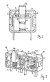
- Fig. 3 is a oblique view of two contact modules arranged in parallel with portions removed.
- Fig. 4 is a oblique view of an example of switch with a portion removed.
- Fig. 5 is a sectional side view of the switch of Fig. 4.
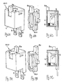
- Figs. 6A, 6B and 6C, together referred to as Fig. 6, are respectively a oblique view of the whole of an example of contact module, a oblique view of its plunger and its sectional side view.
- Figs. 7A, 7B and 7C, together referred to as Fig. 7, are respectively a oblique view of the whole of another example of contact module, a oblique view of its plunger and its sectional side view.
- Fig. 8 is a oblique view of an essential portion of an example of a switch with two contact modules of the kind shown in Fig. 6 and one contact module of the kind shown in Fig. 7.
- Fig. 9 is a oblique view of an essential portion of another example of a switch with three contact modules of the kind shown in Fig. 6, one of them being turned around in a backward direction.
- Figs. 10A, 10B and 10C, together referred to as Fig. 10, and Figs. 11A, 11B and 11C, together referred to as Fig. 11, are still further examples of contact modules, Figs. 10A and 11A being oblique whole views, Figs. 10B and 11B being oblique views of their plungers and Figs. 10C and 11C being their sectional side views.
- Fig. 12 is a oblique view of another switch embodying this invention formed with contact modules of the kinds shown in Figs, 10 and 11.
- Fig. 13 is a sectional front view of another switch using contact modules according to different embodiments of this invention.
- Fig. 1 shows the basic structure of a switch A embodying this invention, incorporating two contact modules M, an
actuator 2 adapted to move like a see-saw and apush button 3 for operating theactuator 2 inside aswitch case 1. - The two contact modules M have the same specifications, each having a normally closed
contact mechanism 5 arranged inside amodule case 4. Thecontact mechanism 5 comprises a mutually facing pair of fixedterminals 6 disposed with a certain interval in between, amobile piece 7 made of a conductive metal plate disposed in opposition to the end parts of the fixedterminals 6 from below, aplunger 8 affixed to and supported by thismobile piece 7 and aspring 9 for urging theplunger 8 slidingly upward. Both fixedterminals 6 protrude downward from the bottom of themodule case 4 so as to be connected to an external lead line. Anoperating part 8a extends from theplunger 8 and protrudes upward from the case. - The
actuator 2 is axially supported by theswitch case 1 so as to be able to swing like a seesaw around a fulcrum (supporting point) p at a position above and between the two contact modules M.The operating parts 8a protruding from the two contact modules M are positioned in opposition to both end parts of theactuator 3. Theactuator 3 is biased by aspiral spring 10 provided to the fulcrum p so as to swing back in a fixed direction. The biasing force of thisspiral spring 10 is stronger than the force by the upwardly biasingspring force 9 such that, according to the illustrated example, theplunger 8 is pushed in on the left-hand side of theactuator 3 under the normal condition when thepush button 3 is not being operated, such that thecontact mechanism 5 of the contact module M on the left-hand side is opened, and thecontact mechanism 5 of the contact module M on the right-hand side is closed with theplunger 8 being moved upward by the biasing force. - If the
push button 2 is operated upon and is pushed down, theactuator 3 is moved in the clockwise direction in the figure against thespring 9 in the contact module M on the right-hand side such that thecontact mechanism 5 of the contact module M on the left-hand side is closed and thecontact mechanism 5 of the contact module M on the right-hand side is opened. - In summary, the switch A for oppositely opening and closing two circuits is thus structured by using two contact modules M having the same specification with a normally closed contact.
- With reference to Fig. 1, if a plurality of junction modules M are arranged in the direction perpendicular to the plane of the figure corresponding to each of the illustrated contact modules M and if the
actuator 2 is made to extend in the same perpendicular direction, a switch capable of opening and closing three or more circuits can be obtained. - Some specific examples of the invention are described next with reference to drawings.
- Fig. 2 is a front view of a specific example of the contact module M, and Fig. 3 is a oblique view of two contact modules M arranged in parallel. The operating
part 8a of theplunger 8 incorporated in this contact module M is at a position removed towards the back edge, and is protruding at a position removed backward from the center of the case. - The contact module M on the right-hand side of Fig. 3 is facing frontward, while that on the left-hand side is facing backward such that the operating
part 8a of the contact module M on the right-hand side and that of the contact module M on the left-hand side are separated in the forward-backward direction. Figs. 4 and 5 show a switch A for two circuits incorporating two contact modules M thus arranged next to each other in opposite orientations. - As shown in Figs. 4 and 5, the
actuator 2 incorporated inside theswitch case 1 of this switch A has a larger width, the axial direction of its fulcrum p being the direction in which the contact modules M are arranged in parallel. As shown in Fig. 4, the distal end (behind the paper plane) of theactuator 2 faces the operatingpart 8a of the contact module M on the right-hand side and the proximal end of theactuator 2 faces the operatingpart 8a of the contact module M on the left-hand side. As theactuator 2 is caused to pivot backward by thestrong spiral spring 10, thecontact mechanism 5 of the contact module M on the right-hand side is opened if thepush button 3 is not being pressed, and thecontact mechanism 5 of the contact module M on the left-hand side is closed. - Figs. 6A, 6B and 6C (together referred to as Fig. 6) and Figs. 7A, 7B and 7C (together referred to as Fig. 7) show examples of contact module M(1) and M(2). Figs. 6A and 7A are oblique views of the entire contact modules M(1) and M(2), Figs. 6B and 7B are oblique views of their plungers 8(1) and 8(2), and Figs, 6C and 7C are their sectional side views. The
contact mechanisms 5 incorporated in these contact modules M(1) and M(2) are also formed to be normally closed, having amobile piece 7 biased to be in contact with a pair of fixedterminals 6. All of their components other than theplunger 8 are the same between the two contact modules M(1) and M(2). - The plunger 8(1) of the contact module M(1) of Fig. 6 has its
operating part 8a at a position displaced towards the front while the plunger 8(2) of the contact module M(2) of Fig. 7 has itsoperating part 8a at a position displaced backwards. It is therefore to be appreciated that two different kinds of contact modules M(1) and M(2) can be produced merely by using plungers of two different kinds 8(1) and 8(2) inmodule cases 4 of the same structure and that a switch A for opening and closing a plurality of circuits such as shown in Figs. 8 and 9 can be easily structured by using these two kinds of contact modules M(1) and M(2). - Fig. 8 shows an example of switch that can thus be obtained by using one of the contact modules M(1) of the kind shown in Fig. 6 and two of the contact modules M(2) of the kind shown in Fig. 7 arranged in the axial direction of the supporting axis of the
actuator 2 having an increased width in the same direction. This switch is adapted to close (or open) two circuits and open (or close) one circuit at the same time. - Fig. 9 shows another example of switch also adapted to close (or open) two circuits and open (or close) one circuit at the same time but by using three contact modules M(1) each having its operating
part 8a displaced towards its front side with one of them (the one at the center in the illustrated example) turned around so as to face backward. - Figs. 10A, 10B and 10C, together referred to as Fig. 10, and Figs. 11A, 11B and 11C, together referred to as Fig. 11, show still further examples of contact modules M(3) and M(4). Figs. 10A and 11A are oblique whole views, Figs. 10B and 11B are oblique views of their
plungers 8 and Figs. 10C and 11C are their sectional side views. Thecontact mechanisms 5 incorporated in these contact modules M(3) and M(4) are also structured similarly to those of the contact modules M(1) and M(2) described above, forming a normally closed mechanism with amobile piece 7 biased so as to contact a pair of fixedterminals 6. In other words, components with the same specifications can also be used for thesecontact mechanisms 5. - The
plungers 8 shown in Figs. 10 and 11 have the same specifications. Each of their components is symmetrically formed in the forward-backward direction, except theiroperating parts 8a which are at shifted positions in the forward-backward direction. If theplunger 8 is contained such that itsoperating part 8a is at a position displaced in the forward direction, the contact module M(3) as shown in Fig. 10A with the operatingpart 8a displaced forward from the center of themodule case 4 is obtained. If theplunger 8 is contained such that itsoperating part 8a is at a position displaced in the backward direction, the contact module M(4) as shown in Fig. 11A with the operatingpart 8a nearly at the center of themodule case 4 is obtained. - It is thus possible to obtain a switch for opening and closing a plurality of circuits by using contact modules of these two different kinds M(3) and M(4), each obtained merely by selectively determining the direction in which the position of the
plunger 8 of the same specification is incorporated. Fig. 12 shows an example of a switch thus obtained, having two contact modules M(4) of the kind with the operatingpart 8a nearly at the center of themodule case 4 and one contact module M(3) of the kind with the operatingpart 8a displaced forward, arranged in the direction of the axis p of the fulcrum of theactuator 2 with an extended width, thus being adapted to open (or close) two circuits with the same open-closed characteristics and to close (or open) simultaneously one circuit with the opposite open-closed characteristics. - Fig. 13 shows another switch A using contact modules according to another embodiment, each incorporating a normally
open contact mechanism 5 having amobile piece 7 biased with aspring 9 in the direction of separating from the fixedterminals 6. Two contact modules M thus formed are arranged such that anactuator 2 adapted to undergo a seesaw-like motion operates on them oppositely for oppositely opening and closing two circuits. In the normallyopen contact mechanism 5, it is preferable to support themobile piece 7 by theplunger 8 and to provide a back-up spring 11 for absorbing any displacement of theplunger 8 in excess of the stroke necessary for switching the contact condition by the backward displacement of themobile piece 7. - The present invention is effectively applicable to switches of many different types such as limit switches, safety switches and door switches.
Claims (9)
- A switch comprising:contact modules each having a module case including a normally closed or normally open contact mechanism and a plunger for operating said contact mechanism;a single actuator having two end parts, said actuator being biased so as to rotate around a supporting axis, said actuator undergoing a rotary motion if a force is applied to one of said end parts so as to operate the plunger of an associated one of said contact modules with at least one of said end parts;a switch case that includes said contact modules and said actuator; anda push button for applying a force on one of said end parts of said actuator from outside said switch case.
- The switch of claim 1 wherein a plurality of said contact modules are arranged along said supporting axis of said actuator.
- The switch of claim 2 wherein said plurality of contact modules have operating parts of said plungers at different positions on both sides of said supporting axis and are all arranged in a same orientation along said supporting axis.
- The switch of claim 2 wherein said plurality of contact modules have operating parts of said plungers at positions displaced from the center of said module case on both sides of said supporting axis, specified ones of said contact modules being arranged in a reversed orientation along said supporting axis.
- The switch of any of claims 1 to 4, wherein said contact modules each include a normally closed contact mechanism.
- The switch of any of claims 1 to 5, wherein said supporting axis is arranged between said contact modules.
- A contact module comprising:a normally open or normally closed contact mechanism having a pair of fixed terminals with fixed contact points and a mobile piece with a pair of mobile contact points corresponding to said fixed terminals;a plunger having an operating part for moving said mobile piece; anda module case including said contact mechanism and said plunger;wherein said operating part of said plunger is eccentrically positioned with respect to said module case.
- A pair of contact modules each comprising:a normally open or normally closed contact mechanism having a pair of fixed terminals with fixed contact points and a mobile piece with a pair of mobile contact points corresponding to said fixed terminals;a plunger having an operating part for moving said mobile piece; anda module case including said contact mechanism and said plunger;wherein at least one of the pair of contact modules is a contact module according to claim 7; andwherein the operating parts of the two contact modules are arranged at mutually different positions with respect to the corresponding module case.
- A pair of contact modules each comprising:a normally open or normally closed contact mechanism having a pair of fixed terminals with fixed contact points and a mobile piece with a pair of mobile contact points corresponding to said fixed terminals;a plunger having an operating part for moving said mobile piece; anda module case incorporating said contact mechanism and said plunger;wherein at least one of the pair of contact modules is a contact module according to claim 7 or 8; andwherein the plungers of said pair have the same specification and the plungers have mutually opposite orientations within the module cases.
Applications Claiming Priority (1)
| Application Number | Priority Date | Filing Date | Title |
|---|---|---|---|
| JP2006241239A JP4779892B2 (en) | 2006-09-06 | 2006-09-06 | Switch and contact module |
Publications (3)
| Publication Number | Publication Date |
|---|---|
| EP1898435A2 true EP1898435A2 (en) | 2008-03-12 |
| EP1898435A3 EP1898435A3 (en) | 2008-06-04 |
| EP1898435B1 EP1898435B1 (en) | 2013-04-10 |
Family
ID=38826554
Family Applications (1)
| Application Number | Title | Priority Date | Filing Date |
|---|---|---|---|
| EP07115798.6A Active EP1898435B1 (en) | 2006-09-06 | 2007-09-06 | Switch and contact modules therefor |
Country Status (5)
| Country | Link |
|---|---|
| US (1) | US7585183B2 (en) |
| EP (1) | EP1898435B1 (en) |
| JP (1) | JP4779892B2 (en) |
| KR (1) | KR100937817B1 (en) |
| CN (1) | CN101140835B (en) |
Families Citing this family (14)
| Publication number | Priority date | Publication date | Assignee | Title |
|---|---|---|---|---|
| JP5619576B2 (en) * | 2010-11-12 | 2014-11-05 | 富士通コンポーネント株式会社 | Connectors and switches |
| US9766704B2 (en) * | 2012-01-27 | 2017-09-19 | Visteon Global Technologies, Inc. | Touch surface and microprocessor assembly |
| US9536689B2 (en) * | 2012-12-12 | 2017-01-03 | Daesung Electric Co., Ltd | Multi-operating switch unit for vehicles |
| JP6161974B2 (en) * | 2013-06-26 | 2017-07-12 | 富士通コンポーネント株式会社 | connector |
| CN104157499A (en) * | 2014-08-15 | 2014-11-19 | 南京双京电器集团有限公司 | Novel insulation phase-change switch |
| CN104240983A (en) * | 2014-09-30 | 2014-12-24 | 绵阳雷迪创微电子科技有限公司 | Improved travel switch structure |
| JP6451471B2 (en) * | 2015-04-10 | 2019-01-16 | オムロン株式会社 | Switch device |
| KR101758260B1 (en) * | 2016-12-09 | 2017-07-14 | 동원산업 주식회사 | Parking brake fixed lamp switch |
| DE102017101097B4 (en) * | 2017-01-20 | 2020-06-25 | Fujitsu Client Computing Limited | Switch arrangement |
| EP3352191B1 (en) * | 2017-01-24 | 2019-01-23 | Würth Elektronik Eisos Gmbh & CO. KG | Program switch and modular program switch arrangement for mounting on a printed circuit board and method for producing such a program switch arrangement |
| US10002721B1 (en) * | 2017-02-27 | 2018-06-19 | Carling Technologies, Inc. | Multiple contact circuit breaker |
| KR200497970Y1 (en) * | 2021-12-24 | 2024-05-03 | 주식회사 제이케이시스템 | A contact structure of a switch, a contact block comprising the contact structure, and a switch comprising the contact block |
| KR102677965B1 (en) * | 2023-07-10 | 2024-06-24 | (주)대성마이크로스위치 | Set of Micro-Switch |
| CN118610021B (en) * | 2024-08-07 | 2024-11-19 | 恒洁智能卫浴(深圳)有限公司 | Electric switch and intelligent closestool |
Family Cites Families (13)
| Publication number | Priority date | Publication date | Assignee | Title |
|---|---|---|---|---|
| US3118026A (en) * | 1960-12-22 | 1964-01-14 | Gen Electric | Push button switch structure |
| US3270154A (en) * | 1963-12-26 | 1966-08-30 | Cleo C Stratton | Dimmer and turn signal control mechanism |
| GB1488761A (en) | 1976-01-21 | 1977-10-12 | Burgess Micro Switch Co Ltd | Electric switching devices |
| US4355216A (en) * | 1981-01-02 | 1982-10-19 | Gte Products Corporation | Electric switch |
| JPS6323858Y2 (en) * | 1981-01-31 | 1988-06-30 | ||
| JPS59112430A (en) * | 1982-12-16 | 1984-06-28 | Matsushita Electric Ind Co Ltd | Magnetic recording tape |
| US4883932A (en) * | 1987-08-21 | 1989-11-28 | Chrysler Motors Corporation | Linkage-type switches for control panel actuators |
| JPH07262865A (en) | 1994-03-17 | 1995-10-13 | Fanuc Ltd | Three-position switch |
| JP2000003636A (en) * | 1998-06-15 | 2000-01-07 | Omron Corp | Limit switch |
| JP3978987B2 (en) | 1999-11-17 | 2007-09-19 | オムロン株式会社 | Detection switch |
| JP3818097B2 (en) | 2001-07-31 | 2006-09-06 | オムロン株式会社 | switch |
| DE20305528U1 (en) * | 2003-04-04 | 2003-08-14 | TRW Automotive Electronics & Components GmbH & Co. KG, 78315 Radolfzell | Push switch |
| KR100633919B1 (en) * | 2004-06-23 | 2006-10-16 | 기아자동차주식회사 | Car Stop Lamp Switch |
-
2006
- 2006-09-06 JP JP2006241239A patent/JP4779892B2/en active Active
-
2007
- 2007-07-26 KR KR1020070074880A patent/KR100937817B1/en not_active Expired - Fee Related
- 2007-08-10 US US11/891,425 patent/US7585183B2/en active Active
- 2007-09-04 CN CN2007101495317A patent/CN101140835B/en active Active
- 2007-09-06 EP EP07115798.6A patent/EP1898435B1/en active Active
Also Published As
| Publication number | Publication date |
|---|---|
| US7585183B2 (en) | 2009-09-08 |
| EP1898435A3 (en) | 2008-06-04 |
| EP1898435B1 (en) | 2013-04-10 |
| CN101140835A (en) | 2008-03-12 |
| CN101140835B (en) | 2013-04-03 |
| JP4779892B2 (en) | 2011-09-28 |
| JP2008066060A (en) | 2008-03-21 |
| US20080053809A1 (en) | 2008-03-06 |
| KR100937817B1 (en) | 2010-01-20 |
| KR20080022495A (en) | 2008-03-11 |
Similar Documents
| Publication | Publication Date | Title |
|---|---|---|
| EP1898435A2 (en) | Switch and contact modules therefor | |
| US5115108A (en) | Two-stage rubber switch | |
| US4095066A (en) | Hinged flyplate actuator | |
| JP2003141971A (en) | Switch device | |
| JP4279648B2 (en) | Switch device | |
| JP2009199981A (en) | Switch for electric power tool | |
| US6841751B2 (en) | Switching device | |
| EP1300859B1 (en) | Switch operating mechanism | |
| EP3859762B1 (en) | Enabling switch | |
| CN102683082A (en) | Switch device | |
| KR101423145B1 (en) | Multi-operation switch device | |
| EP3312861A1 (en) | Electrical pushbutton snap switch with means for identifying the position of the pushbutton and/or of the driving member | |
| KR100689579B1 (en) | Push button switch | |
| JP2008004322A (en) | switch | |
| US20030226748A1 (en) | Switch device | |
| JP2002216587A (en) | Slider activating switch | |
| EP0727795B1 (en) | Sequence switch with forced disconnect mechanism | |
| JP4030735B2 (en) | Switch device | |
| US20140000404A1 (en) | Shift lever device | |
| JP4185576B2 (en) | Switch device | |
| JPH08287783A (en) | switch | |
| JP4715694B2 (en) | switch | |
| JP4528697B2 (en) | Switch device | |
| JPH0729452A (en) | Microswitch | |
| JP4534850B2 (en) | Tumble switch and switch |
Legal Events
| Date | Code | Title | Description |
|---|---|---|---|
| PUAI | Public reference made under article 153(3) epc to a published international application that has entered the european phase |
Free format text: ORIGINAL CODE: 0009012 |
|
| AK | Designated contracting states |
Kind code of ref document: A2 Designated state(s): AT BE BG CH CY CZ DE DK EE ES FI FR GB GR HU IE IS IT LI LT LU LV MC MT NL PL PT RO SE SI SK TR |
|
| AX | Request for extension of the european patent |
Extension state: AL BA HR MK YU |
|
| PUAL | Search report despatched |
Free format text: ORIGINAL CODE: 0009013 |
|
| AK | Designated contracting states |
Kind code of ref document: A3 Designated state(s): AT BE BG CH CY CZ DE DK EE ES FI FR GB GR HU IE IS IT LI LT LU LV MC MT NL PL PT RO SE SI SK TR |
|
| AX | Request for extension of the european patent |
Extension state: AL BA HR MK RS |
|
| 17P | Request for examination filed |
Effective date: 20080819 |
|
| AKX | Designation fees paid |
Designated state(s): DE FR GB IT |
|
| GRAP | Despatch of communication of intention to grant a patent |
Free format text: ORIGINAL CODE: EPIDOSNIGR1 |
|
| RIN1 | Information on inventor provided before grant (corrected) |
Inventor name: FUKUMOTO, TETSUYA Inventor name: TAKENAKA, HIDEMITSU Inventor name: SHIMAZU, KENJI Inventor name: SASAKI, SHUNKICHI |
|
| GRAS | Grant fee paid |
Free format text: ORIGINAL CODE: EPIDOSNIGR3 |
|
| GRAA | (expected) grant |
Free format text: ORIGINAL CODE: 0009210 |
|
| AK | Designated contracting states |
Kind code of ref document: B1 Designated state(s): DE FR GB IT |
|
| REG | Reference to a national code |
Ref country code: GB Ref legal event code: FG4D |
|
| REG | Reference to a national code |
Ref country code: DE Ref legal event code: R096 Ref document number: 602007029609 Country of ref document: DE Effective date: 20130606 |
|
| PLBE | No opposition filed within time limit |
Free format text: ORIGINAL CODE: 0009261 |
|
| STAA | Information on the status of an ep patent application or granted ep patent |
Free format text: STATUS: NO OPPOSITION FILED WITHIN TIME LIMIT |
|
| 26N | No opposition filed |
Effective date: 20140113 |
|
| REG | Reference to a national code |
Ref country code: DE Ref legal event code: R097 Ref document number: 602007029609 Country of ref document: DE Effective date: 20140113 |
|
| REG | Reference to a national code |
Ref country code: FR Ref legal event code: PLFP Year of fee payment: 10 |
|
| REG | Reference to a national code |
Ref country code: FR Ref legal event code: PLFP Year of fee payment: 11 |
|
| REG | Reference to a national code |
Ref country code: FR Ref legal event code: PLFP Year of fee payment: 12 |
|
| PGFP | Annual fee paid to national office [announced via postgrant information from national office to epo] |
Ref country code: DE Payment date: 20240919 Year of fee payment: 18 |
|
| PGFP | Annual fee paid to national office [announced via postgrant information from national office to epo] |
Ref country code: GB Payment date: 20240923 Year of fee payment: 18 |
|
| PGFP | Annual fee paid to national office [announced via postgrant information from national office to epo] |
Ref country code: FR Payment date: 20240924 Year of fee payment: 18 |
|
| PGFP | Annual fee paid to national office [announced via postgrant information from national office to epo] |
Ref country code: IT Payment date: 20240930 Year of fee payment: 18 |