EP1898217A2 - Sample transport rack - Google Patents
Sample transport rack Download PDFInfo
- Publication number
- EP1898217A2 EP1898217A2 EP07016295A EP07016295A EP1898217A2 EP 1898217 A2 EP1898217 A2 EP 1898217A2 EP 07016295 A EP07016295 A EP 07016295A EP 07016295 A EP07016295 A EP 07016295A EP 1898217 A2 EP1898217 A2 EP 1898217A2
- Authority
- EP
- European Patent Office
- Prior art keywords
- sample
- transport rack
- storage medium
- sample transport
- transmission
- Prior art date
- Legal status (The legal status is an assumption and is not a legal conclusion. Google has not performed a legal analysis and makes no representation as to the accuracy of the status listed.)
- Withdrawn
Links
Images

Classifications
-
- G—PHYSICS
- G01—MEASURING; TESTING
- G01N—INVESTIGATING OR ANALYSING MATERIALS BY DETERMINING THEIR CHEMICAL OR PHYSICAL PROPERTIES
- G01N35/00—Automatic analysis not limited to methods or materials provided for in any single one of groups G01N1/00 - G01N33/00; Handling materials therefor
- G01N35/00584—Control arrangements for automatic analysers
- G01N35/00722—Communications; Identification
- G01N35/00732—Identification of carriers, materials or components in automatic analysers
-
- B—PERFORMING OPERATIONS; TRANSPORTING
- B01—PHYSICAL OR CHEMICAL PROCESSES OR APPARATUS IN GENERAL
- B01L—CHEMICAL OR PHYSICAL LABORATORY APPARATUS FOR GENERAL USE
- B01L9/00—Supporting devices; Holding devices
- B01L9/06—Test-tube stands; Test-tube holders
-
- B—PERFORMING OPERATIONS; TRANSPORTING
- B01—PHYSICAL OR CHEMICAL PROCESSES OR APPARATUS IN GENERAL
- B01L—CHEMICAL OR PHYSICAL LABORATORY APPARATUS FOR GENERAL USE
- B01L2300/00—Additional constructional details
- B01L2300/02—Identification, exchange or storage of information
- B01L2300/021—Identification, e.g. bar codes
- B01L2300/022—Transponder chips
-
- B—PERFORMING OPERATIONS; TRANSPORTING
- B01—PHYSICAL OR CHEMICAL PROCESSES OR APPARATUS IN GENERAL
- B01L—CHEMICAL OR PHYSICAL LABORATORY APPARATUS FOR GENERAL USE
- B01L2300/00—Additional constructional details
- B01L2300/02—Identification, exchange or storage of information
- B01L2300/023—Sending and receiving of information, e.g. using Bluetooth®
-
- G—PHYSICS
- G01—MEASURING; TESTING
- G01N—INVESTIGATING OR ANALYSING MATERIALS BY DETERMINING THEIR CHEMICAL OR PHYSICAL PROPERTIES
- G01N35/00—Automatic analysis not limited to methods or materials provided for in any single one of groups G01N1/00 - G01N33/00; Handling materials therefor
- G01N35/00584—Control arrangements for automatic analysers
- G01N35/00722—Communications; Identification
- G01N35/00732—Identification of carriers, materials or components in automatic analysers
- G01N2035/00742—Type of codes
- G01N2035/00782—Type of codes reprogrammmable code
-
- G—PHYSICS
- G01—MEASURING; TESTING
- G01N—INVESTIGATING OR ANALYSING MATERIALS BY DETERMINING THEIR CHEMICAL OR PHYSICAL PROPERTIES
- G01N35/00—Automatic analysis not limited to methods or materials provided for in any single one of groups G01N1/00 - G01N33/00; Handling materials therefor
- G01N35/00584—Control arrangements for automatic analysers
- G01N35/00722—Communications; Identification
- G01N35/00732—Identification of carriers, materials or components in automatic analysers
- G01N2035/00792—Type of components bearing the codes, other than sample carriers
- G01N2035/00801—Holders for sample carriers, e.g. trays, caroussel, racks
Definitions
- the present invention relates to a sample transport rack that is used to retain a sample cup and move a sample inside an analyzer or sample pretreatment apparatus, between apparatuses, and in a sample transport system.
- the sample transport rack is generally used to retain a test tube, microcup, blood collection tube, or other sample cup and move a sample and sample cups inside an analyzer or sample pretreatment apparatus, between the analyzer and sample pretreatment apparatus or other device, or in a sample transport system.
- a bar code was attached to a lateral surface of the sample cup as means for managing the ID of each stored sample (refer, for instance, to JP-A-2003-294764 ).
- a method for managing the ID or other information about a sample by attaching an RFID tag or other IC-based storage medium to or incorporating it into the sample cup has been studied.
- This mechanism directly read the ID or other sample information from a storage medium that was mounted in the sample cup.
- a storage medium for storing the ID or other sample information was mounted or built in the sample transport rack to temporarily store the ID or other sample information about each transported sample and cause the analyzer or sample pretreatment apparatus read such temporarily stored information.
- a test tube, microcup, or blood collection tube is generally used as the sample cup.
- the sample cup is basically cylindrical in shape.
- the bar code was attached to the lateral surface of a test tube or blood collection tube because it is thin and freely flexible. Even when the sample cup was mounted in the sample transport rack and transported, bar code information was optically read through a gap provided in the sample transport rack because the bar code was attached to the lateral surface of the sample cup.
- an RFID tag or other information storage medium having an electronic circuit that uses an electromagnetic wave or the like is not suitable for use with the sample cup.
- the reason is that the RFID tag, which has a long reading distance, is significantly affected by nearby water as it absorbs the electromagnetic wave. It is therefore preferable that a 13.5 MHz band RFID tag unsusceptible to water be used with the sample cup.
- the permissible reading distance that is, the maximum distance permitted between the information storage medium and a read/write mechanism mounted in the apparatus. Therefore, when the 13.5 MHz band RFID tag is attached to the lateral surface of a test tube, it is difficult to steadily acquire information because the reading distance varies depending on vibration caused by sample transport rack movement or test tube orientation or other RFID tag mounting condition. This problem might be avoided by attaching the 13.5 MHz band RFID tag to the bottom surface of a test tube, which does not significantly sway.
- the test tube to which the 13.5 MHz band RFID tag is attached is mounted in a conventional sample transport rack, the information cannot be read because the bottom surface of the test tube is hidden by the sample transport rack.
- An object of the present invention is to provide a sample transport rack that is capable of steadily transmitting information stored in an RFID tag or another storage medium to an analyzer, sample pretreatment apparatus, or another apparatus when the RFID tag or another storage medium is attached to a sample cup mounted in the sample transport rack.
- the present invention makes it possible to steadily transmit information stored in an RFID tag or another storage medium to an analyzer, sample pretreatment apparatus, or other apparatus when the RFID tag or another storage medium is attached to a sample cup mounted in a sample transport rack.
- Fig. 1 is a perspective view illustrating the external configuration of the sample transport rack according to an embodiment of the present invention.
- Fig. 2 is a perspective view illustrating the internal configuration of the sample transport rack according to an embodiment of the present invention.
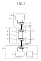
- Fig. 3 is a block diagram illustrating an analysis system that uses the sample transport rack according to an embodiment of the present invention. In Figs. 1 to 3, like reference numerals represent like elements.
- a sample cup 1 is typically a test tube.
- a microcup and a blood collection tube are also sample cups.
- a sample 2 is stored inside the sample cup 1.
- An information storage medium 4 which is typically an RFID tag, is attached to the outer bottom surface of the sample cup 1.
- the information storage medium 4 can store, for instance, an ID for sample identification and reagent information necessary for analysis.
- a bar code 3 is attached to the sample cup 1 for use with an analyzer to permit sample identification.
- the sample cup 1 to which the information storage medium 4 is attached is mounted in the sample transport rack 5 according to the present embodiment.
- the sample transport rack 5 is provided with a sample transmission/reception section 6 and an apparatus transmission/reception section 7.
- the sample transmission/reception section 6 is mounted on the bottom surface of the sample cup 1.
- the apparatus transmission/reception section 7 is mounted on the bottom surface of the sample transport rack 5.
- the sample transmission/reception section 6 and the apparatus transmission/reception section 7 are coupled via an information transmission path 8.
- An analyzer 9 includes an apparatus side transmission/reception circuit 16.
- the apparatus side transmission/reception circuit 16 is controlled by an information processing apparatus 17 to drive an apparatus side transmission/reception coil 14 and generate or receive an electromagnetic wave or alternating magnetic force.
- the apparatus transmission/reception section 7 of the sample transport rack 5 includes an apparatus transmission/reception coil 13.
- the apparatus transmission/reception coil 13 is coupled electromagnetically or magnetically to the apparatus side transmission/reception coil 14 as indicated by an arrow mark 15A.
- the sample transmission/reception section 6 in the sample transport rack 5 includes a sample transmission/reception coil 12.
- the sample transmission/reception coil 12 is electrically coupled to the apparatus side transmission/reception coil 14 via the information transmission path 8.
- the sample transmission/reception coil 12 is coupled electromagnetically or magnetically to a storage medium transmission/reception coil 11 of the information storage medium 4 as indicated by an arrow mark 15B.
- a storage circuit 10 of the information storage medium 4 is electrically coupled to the storage medium transmission/reception coil 11.
- the information transmitted from the apparatus side transmission/reception circuit 16 reaches the storage circuit 10 through the apparatus side transmission/reception coil 14, apparatus transmission/reception coil 13, sample transmission/reception coil 12, and storage medium transmission/reception coil 11.
- the information can then be stored in the storage circuit 10. Further, the information stored in the storage circuit 10 can be transmitted to the apparatus side transmission/reception circuit 16 along a path that is the reverse of the aforementioned path.
- the present embodiment makes it possible to steadily obtain information by preventing the reading distance from varying depending on vibration caused by sample transport rack movement or test tube orientation or another RFID tag mounting condition. Consequently, the present embodiment ensures that the information stored in the RFID tag or another storage medium can be steadily transmitted to an analyzer, sample pretreatment apparatus, or another apparatus.
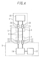
- Fig. 4 is a block diagram illustrating an analysis system that uses the sample transport rack according to another embodiment of the present invention.
- like reference numerals represent like elements.
- the sample transport rack 5 is provided with the sample transmission/reception section 6 and the apparatus transmission/reception section 7.
- the sample transmission/reception section 6 is mounted on the bottom surface of the sample cup 1.
- the apparatus transmission/reception section 7 is mounted on the bottom surface of the sample transport rack 5.
- the sample transmission/reception section 6 and the apparatus transmission/reception section 7 are coupled via the information transmission path 8.
- the analyzer 9 includes the apparatus side transmission/reception circuit 16.
- the apparatus side transmission/reception circuit 16 is controlled by the information processing apparatus 17 to drive an apparatus side contact 23 and generate an electrical signal.
- the apparatus transmission/reception section 7 of the sample transport rack 5 includes an apparatus contact 22.
- the apparatus contact 22 and apparatus side contact 23 can be electrically coupled to or decoupled from each other.
- the sample transmission/reception section 6 includes a sample contact 21.
- the sample contact 21 and apparatus side contact 22 are electrically coupled via the information transmission path 8.
- the information storage medium 4 includes a storage medium contact 20.
- the sample contact 21 can be electrically coupled to or decoupled from the storage medium contact 20 in the information storage medium 4.
- the storage circuit 10 is electrically coupled to the storage medium contact 20.
- the information transmitted from the apparatus side transmission/reception circuit 16 reaches the storage circuit 10 through the apparatus side contact 23, apparatus contact 22, sample contact 21, and storage medium contact 20.
- the information can then be stored in the storage circuit 10. Further, the information stored in the storage circuit 10 can be transmitted to the apparatus side transmission/reception circuit 16 along a path that is the reverse of the aforementioned path.
- the present embodiment makes it possible to steadily obtain information by preventing the reading distance from varying depending on vibration caused by sample transport rack movement or test tube orientation or another RFID tag mounting condition. Consequently, the present embodiment ensures that the information stored in the RFID tag or another storage medium can be steadily transmitted to an analyzer, sample pretreatment apparatus, or another apparatus.
Landscapes
- Chemical & Material Sciences (AREA)
- Health & Medical Sciences (AREA)
- Analytical Chemistry (AREA)
- Chemical Kinetics & Catalysis (AREA)
- Physics & Mathematics (AREA)
- Life Sciences & Earth Sciences (AREA)
- Clinical Laboratory Science (AREA)
- Biochemistry (AREA)
- General Health & Medical Sciences (AREA)
- General Physics & Mathematics (AREA)
- Immunology (AREA)
- Pathology (AREA)
- Automatic Analysis And Handling Materials Therefor (AREA)
Abstract
Description
- The present invention relates to a sample transport rack that is used to retain a sample cup and move a sample inside an analyzer or sample pretreatment apparatus, between apparatuses, and in a sample transport system.
- The sample transport rack is generally used to retain a test tube, microcup, blood collection tube, or other sample cup and move a sample and sample cups inside an analyzer or sample pretreatment apparatus, between the analyzer and sample pretreatment apparatus or other device, or in a sample transport system. In the past, a bar code was attached to a lateral surface of the sample cup as means for managing the ID of each stored sample (refer, for instance, to
JP-A-2003-294764 - A test tube, microcup, or blood collection tube is generally used as the sample cup. In most cases, the sample cup is basically cylindrical in shape. The bar code was attached to the lateral surface of a test tube or blood collection tube because it is thin and freely flexible. Even when the sample cup was mounted in the sample transport rack and transported, bar code information was optically read through a gap provided in the sample transport rack because the bar code was attached to the lateral surface of the sample cup.
- However, an RFID tag or other information storage medium having an electronic circuit that uses an electromagnetic wave or the like is not suitable for use with the sample cup. The reason is that the RFID tag, which has a long reading distance, is significantly affected by nearby water as it absorbs the electromagnetic wave. It is therefore preferable that a 13.5 MHz band RFID tag unsusceptible to water be used with the sample cup.
- However, when the 13.5 MHz band RFID tag is used, the permissible reading distance, that is, the maximum distance permitted between the information storage medium and a read/write mechanism mounted in the apparatus, is short. Therefore, when the 13.5 MHz band RFID tag is attached to the lateral surface of a test tube, it is difficult to steadily acquire information because the reading distance varies depending on vibration caused by sample transport rack movement or test tube orientation or other RFID tag mounting condition. This problem might be avoided by attaching the 13.5 MHz band RFID tag to the bottom surface of a test tube, which does not significantly sway. However, when the test tube to which the 13.5 MHz band RFID tag is attached is mounted in a conventional sample transport rack, the information cannot be read because the bottom surface of the test tube is hidden by the sample transport rack.
- An object of the present invention is to provide a sample transport rack that is capable of steadily transmitting information stored in an RFID tag or another storage medium to an analyzer, sample pretreatment apparatus, or another apparatus when the RFID tag or another storage medium is attached to a sample cup mounted in the sample transport rack.
- (1) To accomplish the above object, according to one aspect of the present invention, there is provided a sample transport rack that retains a sample cup in which a sample is stored and that is used to move the sample. The sample transport rack includes information transmission means for transmitting information stored in an information storage medium attached to the sample cup, which is mounted in the sample transport rack, to a device that uses the sample transport rack, and transmitting information created by the device to the information storage medium.
Since the sample transport rack is configured as described above, it is capable of steadily transmitting information stored in an RFID tag or another storage medium to an analyzer, sample pretreatment apparatus, or another apparatus when the RFID tag or another storage medium is attached to the sample cup mounted in the sample transport rack. - (2) According to another aspect of the present invention, there is provided the sample transport rack as described in (1) above, wherein the information transmission means uses an electromagnetic wave or magnetism.
- (3) According to still another aspect of the present invention, there is provided the sample transport rack as described in (1) above, wherein the information transmission means is an electrical contact that is electrically coupled to the information storage medium and the device.
- The present invention makes it possible to steadily transmit information stored in an RFID tag or another storage medium to an analyzer, sample pretreatment apparatus, or other apparatus when the RFID tag or another storage medium is attached to a sample cup mounted in a sample transport rack.
-
- Fig. 1 is a perspective view illustrating the external configuration of a sample transport rack according to an embodiment of the present invention.
- Fig. 2 is a perspective view illustrating the internal configuration of the sample transport rack according to an embodiment of the present invention.
- Fig. 3 is a block diagram illustrating an analysis system that uses the sample transport rack according to an embodiment of the present invention.
- Fig. 4 is a block diagram illustrating an analysis system that uses the sample transport rack according to another embodiment of the present invention.
- The configuration of a sample transport rack according to an embodiment of the present invention will now be described with reference to Figs. 1 to 3.
- Fig. 1 is a perspective view illustrating the external configuration of the sample transport rack according to an embodiment of the present invention. Fig. 2 is a perspective view illustrating the internal configuration of the sample transport rack according to an embodiment of the present invention. Fig. 3 is a block diagram illustrating an analysis system that uses the sample transport rack according to an embodiment of the present invention. In Figs. 1 to 3, like reference numerals represent like elements.
- As shown in Fig. 1, a sample cup 1 is typically a test tube. A microcup and a blood collection tube are also sample cups. A
sample 2 is stored inside the sample cup 1. An information storage medium 4, which is typically an RFID tag, is attached to the outer bottom surface of the sample cup 1. The information storage medium 4 can store, for instance, an ID for sample identification and reagent information necessary for analysis. In general, abar code 3 is attached to the sample cup 1 for use with an analyzer to permit sample identification. However, the sample cup 1 to which the information storage medium 4 is attached is mounted in the sample transport rack 5 according to the present embodiment. - As shown in Fig. 2, the sample transport rack 5 is provided with a sample transmission/
reception section 6 and an apparatus transmission/reception section 7. The sample transmission/reception section 6 is mounted on the bottom surface of the sample cup 1. The apparatus transmission/reception section 7 is mounted on the bottom surface of the sample transport rack 5. The sample transmission/reception section 6 and the apparatus transmission/reception section 7 are coupled via aninformation transmission path 8. - An operation of the sample transport rack 5 according to the present embodiment will now be described with reference to Fig. 3. An
analyzer 9 includes an apparatus side transmission/reception circuit 16. The apparatus side transmission/reception circuit 16 is controlled by aninformation processing apparatus 17 to drive an apparatus side transmission/reception coil 14 and generate or receive an electromagnetic wave or alternating magnetic force. - The apparatus transmission/
reception section 7 of the sample transport rack 5 includes an apparatus transmission/reception coil 13. The apparatus transmission/reception coil 13 is coupled electromagnetically or magnetically to the apparatus side transmission/reception coil 14 as indicated by an arrow mark 15A. - The sample transmission/
reception section 6 in the sample transport rack 5 includes a sample transmission/reception coil 12. The sample transmission/reception coil 12 is electrically coupled to the apparatus side transmission/reception coil 14 via theinformation transmission path 8. The sample transmission/reception coil 12 is coupled electromagnetically or magnetically to a storage medium transmission/reception coil 11 of the information storage medium 4 as indicated by an arrow mark 15B. - A
storage circuit 10 of the information storage medium 4 is electrically coupled to the storage medium transmission/reception coil 11. - Since the configuration is as described above, the information transmitted from the apparatus side transmission/
reception circuit 16 reaches thestorage circuit 10 through the apparatus side transmission/reception coil 14, apparatus transmission/reception coil 13, sample transmission/reception coil 12, and storage medium transmission/reception coil 11. The information can then be stored in thestorage circuit 10. Further, the information stored in thestorage circuit 10 can be transmitted to the apparatus side transmission/reception circuit 16 along a path that is the reverse of the aforementioned path. - Even when an RFID tag having a short permissible reading distance is attached to a test tube, microcup, blood collection tube, or another sample cup, which is mounted in a sample transport rack for retaining and moving the sample cup, the present embodiment makes it possible to steadily obtain information by preventing the reading distance from varying depending on vibration caused by sample transport rack movement or test tube orientation or another RFID tag mounting condition. Consequently, the present embodiment ensures that the information stored in the RFID tag or another storage medium can be steadily transmitted to an analyzer, sample pretreatment apparatus, or another apparatus.
- The configuration of the sample transport rack according to another embodiment of the present invention will now be described with reference to Fig. 4.
- Fig. 4 is a block diagram illustrating an analysis system that uses the sample transport rack according to another embodiment of the present invention. In Figs. 1 to 4, like reference numerals represent like elements.
- The sample transport rack 5 according to the present embodiment is provided with the sample transmission/
reception section 6 and the apparatus transmission/reception section 7. The sample transmission/reception section 6 is mounted on the bottom surface of the sample cup 1. The apparatus transmission/reception section 7 is mounted on the bottom surface of the sample transport rack 5. The sample transmission/reception section 6 and the apparatus transmission/reception section 7 are coupled via theinformation transmission path 8. - The
analyzer 9 includes the apparatus side transmission/reception circuit 16. The apparatus side transmission/reception circuit 16 is controlled by theinformation processing apparatus 17 to drive anapparatus side contact 23 and generate an electrical signal. The apparatus transmission/reception section 7 of the sample transport rack 5 includes anapparatus contact 22. Theapparatus contact 22 andapparatus side contact 23 can be electrically coupled to or decoupled from each other. - The sample transmission/
reception section 6 includes asample contact 21. Thesample contact 21 andapparatus side contact 22 are electrically coupled via theinformation transmission path 8. Meanwhile, the information storage medium 4 includes astorage medium contact 20. Thesample contact 21 can be electrically coupled to or decoupled from thestorage medium contact 20 in the information storage medium 4. Thestorage circuit 10 is electrically coupled to thestorage medium contact 20. - Since the configuration is as described above, the information transmitted from the apparatus side transmission/
reception circuit 16 reaches thestorage circuit 10 through theapparatus side contact 23,apparatus contact 22,sample contact 21, andstorage medium contact 20. The information can then be stored in thestorage circuit 10. Further, the information stored in thestorage circuit 10 can be transmitted to the apparatus side transmission/reception circuit 16 along a path that is the reverse of the aforementioned path. - Even when an RFID tag having a short permissible reading distance is attached to a test tube, microcup, blood collection tube, or another sample cup, which is mounted in a sample transport rack for retaining and moving the sample cup, the present embodiment makes it possible to steadily obtain information by preventing the reading distance from varying depending on vibration caused by sample transport rack movement or test tube orientation or another RFID tag mounting condition. Consequently, the present embodiment ensures that the information stored in the RFID tag or another storage medium can be steadily transmitted to an analyzer, sample pretreatment apparatus, or another apparatus.
Claims (3)
- A sample transport rack for retaining a sample cup in which a sample is stored and moving the sample, the sample transport rack comprising:information transmission means for transmitting information stored in an information storage medium attached to the sample cup, which is mounted in said sample transport rack, to a device which uses the sample transport rack, and for transmitting information created by said device to said information storage medium.
- The sample transport rack according to claim 1, wherein said information transmission means uses an electromagnetic wave or magnetism.
- The sample transport rack according to claim 1, wherein said information transmission means is an electrical contact that is electrically coupled to said information storage medium and said device.
Applications Claiming Priority (1)
| Application Number | Priority Date | Filing Date | Title |
|---|---|---|---|
| JP2006242307A JP4758307B2 (en) | 2006-09-07 | 2006-09-07 | Sample transport rack and analysis system |
Publications (2)
| Publication Number | Publication Date |
|---|---|
| EP1898217A2 true EP1898217A2 (en) | 2008-03-12 |
| EP1898217A3 EP1898217A3 (en) | 2011-03-30 |
Family
ID=38640111
Family Applications (1)
| Application Number | Title | Priority Date | Filing Date |
|---|---|---|---|
| EP07016295A Withdrawn EP1898217A3 (en) | 2006-09-07 | 2007-08-20 | Sample transport rack |
Country Status (4)
| Country | Link |
|---|---|
| US (1) | US20080063563A1 (en) |
| EP (1) | EP1898217A3 (en) |
| JP (1) | JP4758307B2 (en) |
| CN (1) | CN101140290B (en) |
Cited By (6)
| Publication number | Priority date | Publication date | Assignee | Title |
|---|---|---|---|---|
| EP2000211A1 (en) * | 2007-05-30 | 2008-12-10 | Hitachi High-Technologies Corporation | Specimen rack and specimen carrier system |
| EP2288900A4 (en) * | 2008-06-06 | 2011-06-15 | Capitol Plastic Products L L C | SUPPORT WITH BOTTLE |
| BE1018828A3 (en) * | 2009-07-16 | 2011-09-06 | Praet Peter Van | INTELLIGENT RACK FOR SPECIMEN TUBES AND METHOD OF LOADING THE TUBES INTO THE RACK. |
| FR2957536A1 (en) * | 2010-03-18 | 2011-09-23 | Sas Laboratoire | Test tubes for containing e.g. blood, to be analyzed in laboratory, has reading and/or writing unit that reads and/or writes identifier stored and/or to be stored in chip, where unit is located in circulation path of tube |
| WO2011142749A1 (en) * | 2010-05-12 | 2011-11-17 | Analogic Corporation | Sample carrier identification |
| WO2018163111A1 (en) * | 2017-03-10 | 2018-09-13 | Sato Holdings Kabushiki Kaisha | Container labels |
Families Citing this family (18)
| Publication number | Priority date | Publication date | Assignee | Title |
|---|---|---|---|---|
| US7688207B2 (en) * | 2006-07-28 | 2010-03-30 | Abbott Laboratories Inc. | System for tracking vessels in automated laboratory analyzers by radio frequency identification |
| US20090181359A1 (en) * | 2007-10-25 | 2009-07-16 | Lou Sheng C | Method of performing ultra-sensitive immunoassays |
| US8222048B2 (en) | 2007-11-05 | 2012-07-17 | Abbott Laboratories | Automated analyzer for clinical laboratory |
| JP5431755B2 (en) * | 2008-10-31 | 2014-03-05 | シスメックス株式会社 | Sample analyzer and sample analysis method |
| US20110047188A1 (en) * | 2009-08-24 | 2011-02-24 | Carios Martins | Method and System for Automatic Tracking of Information Technology Components and Corresponding Power Outlets in a Data Center |
| CH702263A1 (en) * | 2009-11-30 | 2011-05-31 | Berlinger & Co | Identifiable container. |
| US20110187503A1 (en) * | 2010-02-01 | 2011-08-04 | Mario Costa | Method and System for Data Center Rack Brackets For Automatic Location Tracking of Information Technology Components |
| US8427301B2 (en) | 2010-06-24 | 2013-04-23 | Avocent Corporation | System and method for identifying electrical equipment using wireless receivers |
| JP6076257B2 (en) * | 2010-11-12 | 2017-02-08 | ジェン−プローブ・インコーポレーテッド | System and method for tracking articles during a process |
| AU2013356680A1 (en) * | 2012-12-05 | 2015-05-28 | Theranos Ip Company, Llc | Systems, devices, and methods for bodily fluid sample collection and transport |
| JP6078355B2 (en) * | 2013-01-28 | 2017-02-08 | 株式会社日立ハイテクノロジーズ | Automatic analyzer and sample rack transport method |
| US9632103B2 (en) | 2013-03-15 | 2017-04-25 | Abbott Laboraties | Linear track diagnostic analyzer |
| CN105164511B (en) | 2013-03-15 | 2019-03-22 | 雅培实验室 | Automated Reagent Manager for Diagnostic Analyzer Systems |
| US9513303B2 (en) | 2013-03-15 | 2016-12-06 | Abbott Laboratories | Light-blocking system for a diagnostic analyzer |
| GB201409077D0 (en) * | 2014-05-21 | 2014-07-02 | Castrol Ltd | Apparatus and method |
| CN104020308B (en) * | 2014-06-20 | 2015-11-25 | 深圳市锦瑞电子有限公司 | A kind of sample introduction mechanism and fluid analysis equipment |
| JP2015045651A (en) * | 2014-10-03 | 2015-03-12 | アナロジック コーポレイション | Identification of sample holding body |
| EP4102228A1 (en) * | 2021-06-11 | 2022-12-14 | F. Hoffmann-La Roche AG | Automated method for handling an in-vitro diagnostics container in an in-vitro diagnostics laboratory |
Family Cites Families (12)
| Publication number | Priority date | Publication date | Assignee | Title |
|---|---|---|---|---|
| JPS60191965A (en) * | 1984-03-14 | 1985-09-30 | Fuji Xerox Co Ltd | Sorter |
| IL94212A0 (en) * | 1989-07-24 | 1991-01-31 | Tri Tech Partners And Triton B | Automated analytical apparatus and method |
| US5777303A (en) * | 1994-09-09 | 1998-07-07 | Gay Freres, Vente Et Exportation S.A. | Device for associating test tube samples with electronic labels for storage of identifying data |
| JP3496447B2 (en) * | 1997-04-10 | 2004-02-09 | 株式会社日立製作所 | Sample rack transport method and automatic analyzer |
| JP3729807B2 (en) * | 2002-12-26 | 2005-12-21 | 照明 伊藤 | Sample transport holder transfer system |
| US7075437B2 (en) * | 2003-01-13 | 2006-07-11 | Symbol Technologies, Inc. | RFID relay device and methods for relaying and RFID signal |
| JP4128491B2 (en) * | 2003-06-16 | 2008-07-30 | 株式会社エスアールエル | Sample rack and sample position recognition system |
| US7382258B2 (en) * | 2004-03-19 | 2008-06-03 | Applera Corporation | Sample carrier device incorporating radio frequency identification, and method |
| WO2005098455A1 (en) * | 2004-04-07 | 2005-10-20 | Tecan Trading Ag | Device and method for identifying, locating and tracking objects on laboratory equipment |
| EP1922403A2 (en) * | 2005-08-09 | 2008-05-21 | Mayo Foundation For Medical Education And Research | Pathology sample processing workstation |
| US8346382B2 (en) * | 2005-08-25 | 2013-01-01 | Coldtrack, Llc | Hierarchical sample storage system |
| EP1870834A1 (en) * | 2006-06-20 | 2007-12-26 | Assa Abloy Identification Technology Group AB | Support for marked articles and article to be accomodated in such support |
-
2006
- 2006-09-07 JP JP2006242307A patent/JP4758307B2/en not_active Expired - Fee Related
-
2007
- 2007-08-09 CN CN2007101403673A patent/CN101140290B/en not_active Expired - Fee Related
- 2007-08-20 EP EP07016295A patent/EP1898217A3/en not_active Withdrawn
- 2007-08-22 US US11/843,336 patent/US20080063563A1/en not_active Abandoned
Non-Patent Citations (1)
| Title |
|---|
| None |
Cited By (9)
| Publication number | Priority date | Publication date | Assignee | Title |
|---|---|---|---|---|
| EP2000211A1 (en) * | 2007-05-30 | 2008-12-10 | Hitachi High-Technologies Corporation | Specimen rack and specimen carrier system |
| US8216511B2 (en) | 2007-05-30 | 2012-07-10 | Hitachi High-Technologies Corporation | Specimen rack and specimen carrier system |
| EP2288900A4 (en) * | 2008-06-06 | 2011-06-15 | Capitol Plastic Products L L C | SUPPORT WITH BOTTLE |
| US8911691B2 (en) | 2008-06-06 | 2014-12-16 | Capitol Plastic Products, Llc | Rack with vial |
| BE1018828A3 (en) * | 2009-07-16 | 2011-09-06 | Praet Peter Van | INTELLIGENT RACK FOR SPECIMEN TUBES AND METHOD OF LOADING THE TUBES INTO THE RACK. |
| FR2957536A1 (en) * | 2010-03-18 | 2011-09-23 | Sas Laboratoire | Test tubes for containing e.g. blood, to be analyzed in laboratory, has reading and/or writing unit that reads and/or writes identifier stored and/or to be stored in chip, where unit is located in circulation path of tube |
| WO2011142749A1 (en) * | 2010-05-12 | 2011-11-17 | Analogic Corporation | Sample carrier identification |
| WO2018163111A1 (en) * | 2017-03-10 | 2018-09-13 | Sato Holdings Kabushiki Kaisha | Container labels |
| US11349192B2 (en) | 2017-03-10 | 2022-05-31 | Sato Holdings Kabushiki Kaisha | Container labels |
Also Published As
| Publication number | Publication date |
|---|---|
| JP4758307B2 (en) | 2011-08-24 |
| EP1898217A3 (en) | 2011-03-30 |
| JP2008064586A (en) | 2008-03-21 |
| US20080063563A1 (en) | 2008-03-13 |
| CN101140290A (en) | 2008-03-12 |
| CN101140290B (en) | 2012-06-06 |
Similar Documents
| Publication | Publication Date | Title |
|---|---|---|
| US20080063563A1 (en) | Sample transport rack | |
| EP2356436B1 (en) | Systems and methods for using ferrite alignment keys in wireless remote sensors | |
| US6343690B1 (en) | Specimen carrier for automated transport system and method and apparatus for identifying same | |
| US20090129990A1 (en) | Rack for sample containers for clinical analyzer | |
| US9431692B2 (en) | Tracking biological and other samples using RFID tags | |
| JP6932518B2 (en) | A storage device for accommodating a sample container and an inspection system using this storage device. | |
| CN102037480B (en) | Disposable sensing device having radio frequency based sensor | |
| EP2080556B1 (en) | A laboratory device for processing samples, a test tube rack, a rack holding assembly and a method to couple an RFID chip | |
| JP3890277B2 (en) | Specimen instruction information creation system | |
| US20100025464A1 (en) | Method and System to Localise and Identify Test Tubes | |
| WO2005027014A3 (en) | Locally storing biological specimen data to a slide | |
| WO2008014117A2 (en) | System for tracking vessels in automated laboratory analyzers by radio frequency identification | |
| EP1837809A1 (en) | Ic tag storing case | |
| JP4955465B2 (en) | Booster antenna | |
| JP2006058219A (en) | Test tube rack | |
| EP1243315A1 (en) | Stirring device and method for measuring a parameter of the substance to be stirred | |
| JP2004028595A (en) | Object detection system and object detection / removal detection system | |
| KR20040103377A (en) | Specimen sorting system | |
| US8585988B2 (en) | Method for creating traceable tissue sample cassettes with RFID technology | |
| CN113935341A (en) | Method and device for detecting pipeline blockage position | |
| JPH09159754A (en) | Data carrier reader |
Legal Events
| Date | Code | Title | Description |
|---|---|---|---|
| PUAI | Public reference made under article 153(3) epc to a published international application that has entered the european phase |
Free format text: ORIGINAL CODE: 0009012 |
|
| AK | Designated contracting states |
Kind code of ref document: A2 Designated state(s): AT BE BG CH CY CZ DE DK EE ES FI FR GB GR HU IE IS IT LI LT LU LV MC MT NL PL PT RO SE SI SK TR |
|
| AX | Request for extension of the european patent |
Extension state: AL BA HR MK YU |
|
| 17P | Request for examination filed |
Effective date: 20080331 |
|
| PUAL | Search report despatched |
Free format text: ORIGINAL CODE: 0009013 |
|
| AK | Designated contracting states |
Kind code of ref document: A3 Designated state(s): AT BE BG CH CY CZ DE DK EE ES FI FR GB GR HU IE IS IT LI LT LU LV MC MT NL PL PT RO SE SI SK TR |
|
| AX | Request for extension of the european patent |
Extension state: AL BA HR MK RS |
|
| AKX | Designation fees paid |
Designated state(s): AT BE BG CH CY CZ DE DK EE ES FI FR GB GR HU IE IS IT LI LT LU LV MC MT NL PL PT RO SE SI SK TR |
|
| 17Q | First examination report despatched |
Effective date: 20160128 |
|
| STAA | Information on the status of an ep patent application or granted ep patent |
Free format text: STATUS: THE APPLICATION IS DEEMED TO BE WITHDRAWN |
|
| 18D | Application deemed to be withdrawn |
Effective date: 20160608 |