EP1898166A2 - Refrigerator - Google Patents
Refrigerator Download PDFInfo
- Publication number
- EP1898166A2 EP1898166A2 EP07115097A EP07115097A EP1898166A2 EP 1898166 A2 EP1898166 A2 EP 1898166A2 EP 07115097 A EP07115097 A EP 07115097A EP 07115097 A EP07115097 A EP 07115097A EP 1898166 A2 EP1898166 A2 EP 1898166A2
- Authority
- EP
- European Patent Office
- Prior art keywords
- shaft
- refrigerator
- duct
- ice
- catch members
- Prior art date
- Legal status (The legal status is an assumption and is not a legal conclusion. Google has not performed a legal analysis and makes no representation as to the accuracy of the status listed.)
- Granted
Links
- 230000007246 mechanism Effects 0.000 claims description 10
- 230000001934 delay Effects 0.000 claims description 2
- 230000003993 interaction Effects 0.000 claims 1
- 238000000034 method Methods 0.000 abstract description 2
- 230000008569 process Effects 0.000 abstract description 2
- 230000008014 freezing Effects 0.000 description 17
- 238000007710 freezing Methods 0.000 description 17
- 239000003507 refrigerant Substances 0.000 description 6
- 238000010586 diagram Methods 0.000 description 4
- 230000004044 response Effects 0.000 description 4
- XLYOFNOQVPJJNP-UHFFFAOYSA-N water Substances O XLYOFNOQVPJJNP-UHFFFAOYSA-N 0.000 description 3
- 238000003780 insertion Methods 0.000 description 2
- 230000037431 insertion Effects 0.000 description 2
- 230000004888 barrier function Effects 0.000 description 1
- 230000000694 effects Effects 0.000 description 1
- 238000009434 installation Methods 0.000 description 1
- 238000012986 modification Methods 0.000 description 1
- 230000004048 modification Effects 0.000 description 1
Images


Classifications
-
- F—MECHANICAL ENGINEERING; LIGHTING; HEATING; WEAPONS; BLASTING
- F25—REFRIGERATION OR COOLING; COMBINED HEATING AND REFRIGERATION SYSTEMS; HEAT PUMP SYSTEMS; MANUFACTURE OR STORAGE OF ICE; LIQUEFACTION SOLIDIFICATION OF GASES
- F25D—REFRIGERATORS; COLD ROOMS; ICE-BOXES; COOLING OR FREEZING APPARATUS NOT OTHERWISE PROVIDED FOR
- F25D17/00—Arrangements for circulating cooling fluids; Arrangements for circulating gas, e.g. air, within refrigerated spaces
- F25D17/04—Arrangements for circulating cooling fluids; Arrangements for circulating gas, e.g. air, within refrigerated spaces for circulating air, e.g. by convection
- F25D17/042—Air treating means within refrigerated spaces
- F25D17/045—Air flow control arrangements
-
- F—MECHANICAL ENGINEERING; LIGHTING; HEATING; WEAPONS; BLASTING
- F25—REFRIGERATION OR COOLING; COMBINED HEATING AND REFRIGERATION SYSTEMS; HEAT PUMP SYSTEMS; MANUFACTURE OR STORAGE OF ICE; LIQUEFACTION SOLIDIFICATION OF GASES
- F25D—REFRIGERATORS; COLD ROOMS; ICE-BOXES; COOLING OR FREEZING APPARATUS NOT OTHERWISE PROVIDED FOR
- F25D25/00—Charging, supporting, and discharging the articles to be cooled
-
- F—MECHANICAL ENGINEERING; LIGHTING; HEATING; WEAPONS; BLASTING
- F25—REFRIGERATION OR COOLING; COMBINED HEATING AND REFRIGERATION SYSTEMS; HEAT PUMP SYSTEMS; MANUFACTURE OR STORAGE OF ICE; LIQUEFACTION SOLIDIFICATION OF GASES
- F25C—PRODUCING, WORKING OR HANDLING ICE
- F25C5/00—Working or handling ice
- F25C5/20—Distributing ice
- F25C5/22—Distributing ice particularly adapted for household refrigerators
-
- F—MECHANICAL ENGINEERING; LIGHTING; HEATING; WEAPONS; BLASTING
- F25—REFRIGERATION OR COOLING; COMBINED HEATING AND REFRIGERATION SYSTEMS; HEAT PUMP SYSTEMS; MANUFACTURE OR STORAGE OF ICE; LIQUEFACTION SOLIDIFICATION OF GASES
- F25D—REFRIGERATORS; COLD ROOMS; ICE-BOXES; COOLING OR FREEZING APPARATUS NOT OTHERWISE PROVIDED FOR
- F25D17/00—Arrangements for circulating cooling fluids; Arrangements for circulating gas, e.g. air, within refrigerated spaces
- F25D17/04—Arrangements for circulating cooling fluids; Arrangements for circulating gas, e.g. air, within refrigerated spaces for circulating air, e.g. by convection
- F25D17/06—Arrangements for circulating cooling fluids; Arrangements for circulating gas, e.g. air, within refrigerated spaces for circulating air, e.g. by convection by forced circulation
- F25D17/08—Arrangements for circulating cooling fluids; Arrangements for circulating gas, e.g. air, within refrigerated spaces for circulating air, e.g. by convection by forced circulation using ducts
-
- F—MECHANICAL ENGINEERING; LIGHTING; HEATING; WEAPONS; BLASTING
- F25—REFRIGERATION OR COOLING; COMBINED HEATING AND REFRIGERATION SYSTEMS; HEAT PUMP SYSTEMS; MANUFACTURE OR STORAGE OF ICE; LIQUEFACTION SOLIDIFICATION OF GASES
- F25D—REFRIGERATORS; COLD ROOMS; ICE-BOXES; COOLING OR FREEZING APPARATUS NOT OTHERWISE PROVIDED FOR
- F25D23/00—General constructional features
-
- F—MECHANICAL ENGINEERING; LIGHTING; HEATING; WEAPONS; BLASTING
- F25—REFRIGERATION OR COOLING; COMBINED HEATING AND REFRIGERATION SYSTEMS; HEAT PUMP SYSTEMS; MANUFACTURE OR STORAGE OF ICE; LIQUEFACTION SOLIDIFICATION OF GASES
- F25C—PRODUCING, WORKING OR HANDLING ICE
- F25C2400/00—Auxiliary features or devices for producing, working or handling ice
- F25C2400/10—Refrigerator units
-
- Y—GENERAL TAGGING OF NEW TECHNOLOGICAL DEVELOPMENTS; GENERAL TAGGING OF CROSS-SECTIONAL TECHNOLOGIES SPANNING OVER SEVERAL SECTIONS OF THE IPC; TECHNICAL SUBJECTS COVERED BY FORMER USPC CROSS-REFERENCE ART COLLECTIONS [XRACs] AND DIGESTS
- Y10—TECHNICAL SUBJECTS COVERED BY FORMER USPC
- Y10T—TECHNICAL SUBJECTS COVERED BY FORMER US CLASSIFICATION
- Y10T74/00—Machine element or mechanism
- Y10T74/20—Control lever and linkage systems
- Y10T74/20012—Multiple controlled elements
- Y10T74/20018—Transmission control
- Y10T74/20134—Transmission control having vibration damper
-
- Y—GENERAL TAGGING OF NEW TECHNOLOGICAL DEVELOPMENTS; GENERAL TAGGING OF CROSS-SECTIONAL TECHNOLOGIES SPANNING OVER SEVERAL SECTIONS OF THE IPC; TECHNICAL SUBJECTS COVERED BY FORMER USPC CROSS-REFERENCE ART COLLECTIONS [XRACs] AND DIGESTS
- Y10—TECHNICAL SUBJECTS COVERED BY FORMER USPC
- Y10T—TECHNICAL SUBJECTS COVERED BY FORMER US CLASSIFICATION
- Y10T74/00—Machine element or mechanism
- Y10T74/21—Elements
- Y10T74/2121—Flywheel, motion smoothing-type
- Y10T74/213—Damping by increasing frictional force
Abstract
Description
- The present invention relates to a refrigerator, and more particularly, to a refrigerator having an ice dispenser and a delay mechanism for delaying the closing of an ice duct of the ice dispenser.
- In general, a refrigerator is a device having a refrigerating chamber and a freezing chamber which are maintained at predetermined low temperatures. The refrigerator uses a refrigerating cycle device with a refrigerant, including a compressor, a condenser, an expander, and an evaporator.
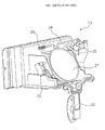
- FIG. 1 is a perspective view of a conventional refrigerator with a refrigerating chamber and a freezing chamber opened. As shown in FIG. 1, the refrigerator includes a refrigerating chamber F and a freezing chamber R, which are separated by a
barrier 1. A refrigerating cycle device for keeping the refrigerating chamber F and the freezing chamber R at low temperatures is installed within themain body 2. A refrigeratingchamber door 6 is coupled to themain body 2 for opening and closing the refrigerating chamber F, and afreezing chamber door 4 is coupled to themain body 2 for opening and closing the freezing chamber R. - The refrigerating cycle device typically includes a compressor for compressing a low temperature and low pressure gas refrigerant, a condenser for condensing the high temperature and high pressure refrigerant by radiating the heat of the compressed refrigerant through external air, an expander for reducing the pressure of the condensed refrigerant from the condenser, and an evaporator for absorbing the heat from air circulating around the refrigerating chamber F and/or the freezing chamber R using the expanded refrigerant.
- An automatic ice maker is often mounted in the freezing chamber of the refrigerator. The automatic ice maker automatically makes ice cubes using cool air in the freezing chamber F. An ice dispenser in the
freezing chamber door 4 can be used to automatically output the ice cubes in response to a user's operation. - The automatic ice maker typically includes an ice making
unit 8 for freezing water to make ice cubes using cool air in the freezing chamber F. Anice bank 9 is used to store ice cubes produced in theice making unit 8. Theice bank 9 includes a conveying member for dispensing ice cubes from theice bank 9, and amotor 10 for rotating the conveying member. Thefreezing chamber door 4 includes a dispenser (not shown) for dispensing ice cubes, and for also dispensing water from a water supply (not shown). - The
freezing chamber door 4 includes anice duct 12 which guides ice cubes dispensed from theice bank 9 to the user outside thedoor 4. An ice duct opening and closingunit 13 is used for opening and closing theice duct 12. - FIG. 2 is a perspective view of an ice duct opening and closing unit of the refrigerator shown in FIG. 1, and FIG. 3 is a block diagram illustrating the elements of the automatic ice maker shown in FIG. 1.
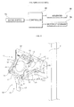
- The ice duct opening and
closing unit 13 shown in FIG. 2 includes aduct cap 21 disposed to open and close theice duct 12. Alever 22 is operated by a user to cause theduct cap 21 to selectively open and close. Amicro switch 23 is turned on/off by thelever 22. A rotatingshaft 24 is disposed to rotate theduct cap 21. Asolenoid 25 is used to cause the rotatingshaft 24 to rotate theduct cap 21 to a position that opens theice duct 12 or to a position that closes theice duct 12. Aspring 26 is disposed to elastically bias the rotatingshaft 24 and theduct cap 24 to the closed position. The refrigerator further includes acontroller 30 for operating themotor 10 and thesolenoid 24 in response to the input of themicro switch 23. - Hereinafter, the operation of outputting ice cubes of the conventional refrigerator will be described.
- When a user pushes the
lever 22, that is, a user applies force to thelever 22, the movement of thelever 22 turns themicro switch 23 on. The signal from themicroswitch 23 causes thecontroller 30 to drive thesolenoid 25 and the motor of theice bank 9. Thesolenoid 25 rotates therotating shaft 25, and the rotatingshaft 25 rotates theduct cap 21, thereby opening theice duct 12. When themotor 10 of theice bank 9 is driven, theice bank 9 outputs ice cubes, and the outputted ice cubes are dropped into theice duct 12. The dropped ice cubes are outputted by the dispenser through the openedice duct 12. - When the user releases the
lever 22, that is, the user removes the force applied to thelever 22, reverse movement of thelever 22 turns off themicro switch 23. In response, thecontroller 30 stops the motor of the ice bank so that ice cubes are no longer removed from the ice bank. The controller will also cause thesolenoid 25 to move back to its original position, but only after a predetermined period of time, for example, four seconds, has elapsed. In other words, the controller does not instantly move the solenoid back to the original position. The delay allows any ice cubes that have been removed from the ice bank to fall out of the ice duct before the duct cap closes the ice duct. - When the
solenoid 25 moves back to its original position, thespring 26 rotates therotating shaft 24, and the attachedduct cap 21, back to the closed position, thereby closing theice duct 12. - The conventional refrigerator includes the
solenoid 25 for closing the duct cap after delaying it for a predetermined time as described above. The solenoid, however, increases the cost of the conventional refrigerator, and the solenoid generates noise when it operates. - The embodiments will be described in detail with reference to the following drawings in which like reference numerals refer to like elements, and wherein:
- FIG. 1 is a perspective view of a related art refrigerator with a refrigerating chamber and a freezing chamber opened;
- FIG. 2 is a perspective view of an ice duct opening and closing unit for a refrigerator as shown in FIG. 1;
- FIG. 3 is a block diagram illustrating elements of an automatic ice maker for a refrigerator as shown in FIG. 1;
- FIG. 4 is a perspective view of an ice duct opening and closing unit of a refrigerator according to a first embodiment;
- FIG. 5 is a cross-sectional view of a time delay unit while opening a duct cap of the mechanism shown in FIG. 4;
- FIG. 6 is a cross-sectional view of the time delay after opening a duct cap of the mechanism shown in FIG. 4;
- FIG. 7 is a cross-sectional view of the time delay while closing a duct cap of the mechanism shown in FIG. 4;
- FIG. 8 is a cross-sectional view of the time delay after closing a duct cap of the mechanism shown in FIG. 4; and
- FIG. 9 is a diagram illustrating a duct cap closing and opening according to the operation of the mechanism shown in FIG. 4.
- FIG. 4 is a perspective view of an ice duct opening and closing unit of a refrigerator according to a first embodiment. The refrigerator according to the first embodiment includes an ice duct opening and closing
unit 13 for opening and closing anice duct 12 in response to the operation of a user. The ice duct opening andclosing unit 13, as shown in FIG. 4, includes afunnel 51 mounted on afreezing chamber door 4 through joint members such as screws. Thefunnel 51 serves as an installation plate for rotatably supporting alever 62 and aduct cap shaft 70 of an opening and closing unit. Thefunnel 51 prevents ice cubes output from theice duct 12 from bouncing in a forward direction or a side direction of the dispenser. Aduct unit 52 is formed at the bottom of theice duct 12. - A
micro switch 90 is disposed on thefunnel 51. Themicroswitch 90 is activated by alever 62 of the opening andclosing unit 60. It is preferable to dispose themicro switch 90 at the side of theduct unit 52. - The ice duct opening and
closing unit 13 includes aduct cap 58 for opening and closing theice duct 12. An opening andclosing unit 60 for opening and closing theduct cap 58 includes a spiral type time delay unit 100 for delaying closing of the duct cap when the opening andclosing unit 60 closes theduct cap 58. - The
duct cap 58 is rotatably or slidably mounted on theice duct 12. Hereinafter, an embodiment will be described where theduct cap 58 is rotatably mounted. However, in other embodiments, the duct cap could also be mounted so that it moves in different fashions. - The
duct cap 58 is disposed to rotate in forward and backward directions along a top edge thereof. That is, theduct cap 58 is inserted inside theduct unit 52 of thefunnel 51 so that it can rotate to open or close theice duct 12. - The opening and closing
unit 60 opens and closes theduct cap 58 manually. The opening andclosing unit 60 includes alever 62 operated by a user, and aduct cap shaft 70 mechanically connected to thelever 62 for rotating theduct cap 58. The opening andclosing unit 60 further includes a spring 80 for elastically supporting at least one of thelever 62 and theduct cap shaft 70 to bias theduct cap 58 towards the closed position. In this embodiment, the spring 80 has one side connected to thefunnel 51 and the other side connected to theduct cap shaft 70. The spring 80 can be a coil spring or a torsion spring. - The
lever 62 includes avertical bar 63 disposed inside the dispenser such that it can be pushed by a user in a backward direction. Left and righthorizontal bars vertical bar 63 to the right side and the left side, respectively. The horizontal bars are rotatably supported by thelever supporting units duct unit 52. Aswitch connecting bar 66 extends from one of the left and righthorizontal bars micro switch 90. A ductcap connecting bar 67 extends from the other of the left and righthorizontal bars duct cap shaft 70. - The
duct cap shaft 70 is disposed at a top side of theduct unit 52 of thefunnel 51. Theduct cap shaft 70 is rotatably supported by a shaft supporting member formed at the top side of theduct unit 52 of thefunnel 51. Theduct cap shaft 70 includes a connectingmember 72, which interacts with the duct capshaft connecting bar 67. Thelever 62 is also coupled to a timedelay connecting bar 68 which operates a time delay unit 100. Thus, thelever 62 is operably connected to arotating shaft 110 in the time delay unit 100. Hereinafter, the time delay connecting bar will be described as a rotatingshaft connecting bar 68. - The time delay unit 100 is connected to one of the
duct cap 58 and the opening andclosing unit 60 and operates to delay closing of theduct cap 58 when the opening andclosing unit 60 closes theduct cap 58. It is preferable that the time delay unit 100 not disturb the rotation of thelever 62 and theduct cap shaft 70 as they move from the closed to the open position, thereby allowing the duct cap to quickly open. It is also preferable that the time delay unit 100 be configured to delay closing of the duct cap for a predetermined period of time, and then allow thelever 62 and theduct cap shaft 70 to move quickly toward the closed position after the predetermined time period has expired. - FIG. 5 is a cross-sectional view of the time delay unit in an operational state where it is moving while the duct cap shown is opening. FIG. 6 is a cross-sectional view of the time delay unit after the duct cap has opened. FIG. 7 is a cross-sectional view of the time delay unit in an operational state where it is moving while the duct cap is closing. FIG. 8 is a cross-sectional view of the time delay unit after the duct cap has closed.
- The time delay unit 100 includes a
rotating shaft 110 that is rotatably connected to the rotatingshaft connecting bar 68, which itself is connected to thelever 62 of the opening andclosing unit 60.Foldaway catching members shaft 110 such that they can bend in one direction. Ascrew member 140 is formed on the inside wall of the time delay unit 100. Thescrew thread member 140 causes thefoldaway catching members rotating shaft 110 moves in an insertion direction I. When therotating shaft 110 moves in a withdrawal direction (O), as shown in Fig. 7, thescrew thread member 140 interacts with the catchingmembers shaft 110 to rotate. - As shown in FIG. 6 through FIG. 8, the
rotating shaft 110 includeshangers foldaway catching members shaft 110 such that they are approximately parallel to therotating shaft 110. In some embodiments, however, the foldaway catching members may not fold all the way up so that they become parallel to theshaft 110. In other words, they may fold upward so that they are at an angle with respect to theshaft 110. Thefoldaway catching members hangers hinge members - The
foldaway catching members hangers rotating shaft 110, and so that they can fold upward to be parallel with therotating shaft 110. Thefoldaway catching members hangers hinge members - The
foldaway catching members hangers foldaway catching members rotation shaft 110. However, thefoldaway catching members hangers rotating shaft 110. - It is preferable that the time delay unit include a plurality of the
foldaway catching members foldaway catching members rotating shaft 110. - The
screw member 140 is formed in a hollow cylindrical shape to allow therotating shaft 110 to move forwardly and backwardly within the hollow cylinder. The cylindrical screw member is positioned on thefunnel 51 such that when thelever 62 is moved by a user, therotating shaft 110 will advance straight down into the cylindrical cavity. - The
screw member 140 includes ascrew thread 144 formed on the inner circumference of anouter body 142 having a hollow cylindrical shape. Thescrew threads 144 bend thefoldaway catching members rotating shaft 110 when therotating shaft 110 moves in an insertion direction (I). However, when therotating shaft 110 moves in a withdrawal direction (O) thefoldaway catching members - The longer the length of the
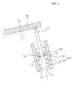
screw groove 144, the longer thefoldaway catching members shaft 110 moves in the withdrawal direction. Also, the longer length of thescrew groove 144, the greater the friction between thescrew groove 144 and thefoldaway catching members duct cap 58, one can increase the length of thescrew groove 144. On the other hand, to shorten the delay time, one can shorten the length of thescrew groove 144. - FIG. 9 is a diagram illustrating a process where a duct cap is closing and opening using the mechanism shown in FIG. 4. When a user pushes the
vertical bar 63 of thelever 62, thehorizontal bars lever supporting units funnel 51. As a result, the ductcap connecting bar 67 rotates theduct cap shaft 70. Rotation of theduct cap shaft 70 elastically deforms the spring 80, and rotates theduct cap 58 so that it starts opening theice duct 12. - When the duct cap
shaft connecting bar 67 rotates theduct cap shaft 70 and theduct cap 58 as described above, the opening force (Fu) is applied to therotating shaft 110 as shown in FIG. 5. As a result, the rotating shaft 100 moves to the bottom of thescrew member 140, as shown in FIG. 6. - While the rotating shaft 100 moves downwardly, the
foldaway catching members rotating shaft 110. As noted above, in some embodiments, the foldaway catching members may not rotate fully upward so that they are parallel to the shaft. Instead, they may only rotate partially upward so that they are at an angle with respect to the shaft. In any event, because the foldaway catching members can rotate upward with respect to the shaft, therotating shaft 110 and thefoldaway catching members screw member 140 through the internal space of thescrew groove 144. - Once, the
rotating shaft 110 is deeply inserted into the bottom of thescrew member 140, shown in FIG. 6, thefoldaway catching members rotating shaft 110. In some embodiments, the foldaway catching members may be spring loaded so that they automatically move to the deployed position once the shaft is filly inserted in thescrew member 140. At this point, theduct cap 58 completely opens theice duct 12. - The movement of the
lever 62 also causes theswitch connecting bar 66 to turn on themicro switch 90. As a result, thecontroller 30 receives a signal from themicro switch 90, which causes thecontroller 30 to drive themotor 10 of theice bank 9. When themotor 10 of theice bank 9 is driven, ice cubes contained in theice bank 9 are dropped into theice duct 12, and the ice cubes are output from the dispenser through the openedice duct 12 and theduct unit 52 of thefunnel 51. - When a user releases the
lever 62, the spring 80 acts to rotate theduct cap 58 back to the closed position. When theduct cap shaft 70 and thelever 62 begin to rotate towards the closed position, theswitch connecting bar 66 of thelever 62 turns off themicro switch 90. As a result, thecontroller 30 stops the motor of theice bank 9, and ice cubes are no longer removed from theice bank 9. - The restoring force of the spring 80 is also applied to the
rotating shaft 110. This force is shown as (Fs) in FIG. 7. The force (Fs) acts to pull therotating shaft 110 out of thehousing 142. The movement of the rotating shaft upward also rotates therotating shaft 110 because the restoring force (Fs) of the spring 80 is greater than the frictional force of thescrew groove 144. Thefoldaway catching members screw groove 144, thereby moving toward the top of thescrew member 140, as shown in FIG. 7. - Because the
foldaway catching members screw groove 144 while rubbing thescrew groove 144, it takes a certain amount of time for the catchingmembers screw groove 144. This delays the closing theice duct 12. The delay ensures that any ice cubes removed from theice bank 9 fall through theice duct 12 before theduct cup 58 closes. - When the
foldaway catching members screw groove 144, the frictional force between the foldaway catchingmembers screw groove 144 disappears, and the restoring force (Fs) of the spring 80 is used to quickly move theduct cap 58 to the closed position. - The foregoing exemplary embodiments and aspects of the invention are merely exemplary and are not to be construed as limiting the present invention. The present invention can be applied to a refrigerator having the
ice maker 8 and theice bank 9 mounted at the rear side of the freezingchamber door 4. The present teaching can be readily applied to other types of apparatuses. Also, the description of the exemplary embodiments of the present invention is intended to be illustrative, and not to limit the scope of the claims, and many alternatives, modifications, and variations will be apparent to those skilled in the art. - The refrigerator and ice dispensing mechanism described above have several advantages. The mechanical time delay unit, having the rotating shaft, the foldaway catching members, and the screw member, act to delay closing of the duct cap without the need for a separate electrically operated solenoid. Therefore, the cost and the operation noise can be minimized compared to a refrigerator with a solenoid. In addition, the foldaway catching members are folded by the screw member and are automatically unfolded. Therefore, a simple structure can smoothly open the duct cap and delay closing the duct cap. Further, because the duct cap shaft and the mechanical time delay unit can be connected through one lever, the structure can be simplified and the number of parts can be minimized.
- Any reference in this specification to "one embodiment," "an embodiment," "example embodiment," etc., means that a particular feature, structure, or characteristic described in connection with the embodiment is included in at least one embodiment of the invention. The appearances of such phrases in various places in the specification are not necessarily all referring to the same embodiment. Further, when a particular feature, structure, or characteristic is described in connection with any embodiment, it is submitted that it is within the purview of one skilled in the art to effect such feature, structure, or characteristic in connection with other ones of the embodiments.
Claims (21)
- A refrigerator, comprising:a main body;an ice dispenser mounted on the main body and having an ice duct for dispensing ice;a duct cap that moves between an open position and a closed position to open and close the ice duct; anda delay unit that delays movement of the duct cap between the open and closed positions for a predetermined period of time, wherein the delay unit comprises:a hollow, elongated body having screw threads on an inner surface;a shaft mounted within the hollow body, wherein the shaft is operably coupled to the duct cap such that the shaft moves into and out of the hollow body as the duct cap moves between the open and closed positions; andfolding catch members mounted on the shaft.
- The refrigerator of claim 1, wherein the folding catch members move between a folded position where they are folded back against the shaft, and a deployed position where they extend out from the shaft.
- The refrigerator of claim 2, wherein when the duct cap opens and the shaft is moving into the hollow body, the folding catch members assume the folded position so that the shaft can move easily and quickly into the hollow body, thereby allowing the duct cap to quickly and easily open.
- The refrigerator of claim 3, wherein when the duct cap closes and the shaft is moving out of the hollow body, the folding catch members assume the deployed position.
- The refrigerator of claim 4, wherein when the shaft is moving out of the hollow body, and the folding catch members are in the deployed position, the folding catch members interact with the screw threads to cause the shaft to rotate.
- The refrigerator of claim 5, wherein the interaction between the folding catch members and the screw threads causes the shaft to move slowly out of the hollow body, thereby causing the duct cover to move slowly from the open to the closed position.
- The refrigerator of claim 2, wherein the folding catch members are attached to the shaft by hinges that allow the folding catch members to rotate between the folded and deployed positions.
- The refrigerator of claim 7, wherein the hinges include stoppers that hold the folding catch members in the deployed position.
- The refrigerator of claim 2, wherein when the shaft is moving into the hollow body, contact between the folding catch members and the screw threads causes the folding catch members to move to the folded position.
- The refrigerator of claim 2, wherein the folding catch members are biased towards the deployed position.
- The refrigerator of any of claims 1 to 10, further comprising:a lever that is operably coupled to the duct cap, wherein the lever can be operated by the user to move the duct cap to the open position; anda spring that is operably coupled to the duct cap and that biases the duct cap towards the closed position.
- The refrigerator of claim 11, wherein the shaft is coupled to the lever such that when a user pushes the lever, the shaft moves into the hollow body.
- The refrigerator of any of claims 1 to 12, wherein the duct cap is rotatably mounted on the ice dispenser such that it rotates between the open and closed positions.
- A refrigerator, comprising:a main body;an ice dispenser mounted on the main body and having an ice duct;a duct cap that is rotatably mounted on the ice dispenser and that moves between open and closed positions that open and close the ice duct; anda delay unit that is operably coupled to the duct cap and that acts to delay a closing operation of the duct cap, wherein the delay unit includes a screw mechanism to provide the delay.
- The refrigerator of claim 14, wherein the screw mechanism comprises:a hollow cylindrical body having internal threads; anda shaft that moves into and out of the hollow cylindrical body as the duct cap moves between the open and closed positions.
- The refrigerator of claim 15, wherein folding catch members are mounted on the shaft, and wherein the folding catch members are movable between folded positions adjacent the shaft and deployed positions where the catch members extend out away from the shaft.
- The refrigerator of claim 16, wherein when the shaft is moving in a first direction within the hollow body, the threads cause the folding catch members to move to the folded position.
- The refrigerator of claim 17, wherein when the shaft is moving in a second direction within the hollow body, the folding catch members assume the deployed position and interact with the threads to cause the shaft to rotate.
- The refrigerator of claim 18, wherein the folding catch members are biased towards the deployed position.
- The refrigerator of claim 16, wherein the folding catch members are hinged to the shaft.
- A refrigerator comprising:an ice duct for conveying ice to outside the refrigerator;a duct cap for opening and closing the ice duct;an opening and closing unit connected to the duct cap to open and close the duct cap; anda spiral time delay unit having folding catch members connected to the opening and closing unit, wherein the catch members rotate along a threaded member to delay closing of the duct cap.
Applications Claiming Priority (1)
| Application Number | Priority Date | Filing Date | Title |
|---|---|---|---|
| KR1020060085229A KR101275560B1 (en) | 2006-09-05 | 2006-09-05 | Refrigerator |
Publications (3)
| Publication Number | Publication Date |
|---|---|
| EP1898166A2 true EP1898166A2 (en) | 2008-03-12 |
| EP1898166A3 EP1898166A3 (en) | 2016-02-17 |
| EP1898166B1 EP1898166B1 (en) | 2017-05-17 |
Family
ID=38961956
Family Applications (1)
| Application Number | Title | Priority Date | Filing Date |
|---|---|---|---|
| EP07115097.3A Expired - Fee Related EP1898166B1 (en) | 2006-09-05 | 2007-08-28 | Refrigerator |
Country Status (4)
| Country | Link |
|---|---|
| US (1) | US7673469B2 (en) |
| EP (1) | EP1898166B1 (en) |
| KR (1) | KR101275560B1 (en) |
| CN (1) | CN100582619C (en) |
Families Citing this family (7)
| Publication number | Priority date | Publication date | Assignee | Title |
|---|---|---|---|---|
| KR100820818B1 (en) | 2006-11-13 | 2008-04-11 | 엘지전자 주식회사 | Dispensing device and refrigerator using the same |
| KR20100061185A (en) * | 2008-11-28 | 2010-06-07 | 엘지전자 주식회사 | Refrigerator having diepenser |
| JP2010203741A (en) * | 2009-03-05 | 2010-09-16 | Panasonic Corp | Refrigerator |
| US8413460B2 (en) * | 2009-06-22 | 2013-04-09 | Samsung Electronics Co., Ltd. | Lever for dispenser and refrigerator having the same |
| US9581382B2 (en) | 2009-06-22 | 2017-02-28 | Samsung Electronics Co., Ltd. | Lever for dispenser and refrigerator having the same |
| US9004325B2 (en) | 2012-11-06 | 2015-04-14 | Whirlpool Corporation | Domestic refrigerator including an ice dispenser |
| US10401072B2 (en) * | 2015-08-31 | 2019-09-03 | Lg Electronics Inc. | Refrigerator |
Family Cites Families (27)
| Publication number | Priority date | Publication date | Assignee | Title |
|---|---|---|---|---|
| US1218197A (en) * | 1916-04-14 | 1917-03-06 | Eben H Mackinlay | Door-check. |
| US3218985A (en) * | 1963-09-03 | 1965-11-23 | Merla Tool Corp | Flow control method and apparatus |
| US3342040A (en) * | 1966-05-25 | 1967-09-19 | Manitowoc Co | Apparatus for making frozen products |
| ES407795A1 (en) * | 1972-10-20 | 1975-11-01 | San Pablo De La Rosa | Hydraulic shock absorber of the telescopic type |
| US3942334A (en) * | 1975-01-08 | 1976-03-09 | Amana Refrigeration, Inc. | Door delay closing mechanism for the ice chute from a power driven ice dispenser in a freezer-refrigerator |
| US4089436A (en) * | 1976-08-26 | 1978-05-16 | Whirlpool Corporation | Refrigerator ice door mechanism |
| US4090641A (en) * | 1976-08-26 | 1978-05-23 | Whirlpool Corporation | Refrigerator ice door mechanism |
| US4109455A (en) * | 1977-05-26 | 1978-08-29 | The United States Of America As Represented By The Secretary Of The Army | Spiral orifice dashpot timer |
| US4759428A (en) * | 1986-07-29 | 1988-07-26 | Nhk Spring Co., Ltd. | Viscoelastic damper |
| NZ248935A (en) * | 1992-11-02 | 1995-10-26 | White Consolidated Ind Inc | Refrigerator door ice dispenser: actuator dimensioned to accommodate polystyrene cup |
| KR100286034B1 (en) * | 1997-12-29 | 2001-05-02 | 윤종용 | Air damper of dispenser for refrigerator |
| KR19990060081A (en) * | 1997-12-31 | 1999-07-26 | 윤종용 | Dispenser Damper in Refrigerator |
| JP3112450B2 (en) * | 1998-03-03 | 2000-11-27 | 三星電子株式会社 | Refrigerator ice dispenser |
| KR20000003901U (en) * | 1998-07-30 | 2000-02-25 | 윤종용 | Refrigerator dispenser |
| US6290038B1 (en) * | 1999-03-29 | 2001-09-18 | Lord Corporation | Elastomer damper |
| US6533003B1 (en) * | 1999-12-30 | 2003-03-18 | General Electric Company | Ice dispenser duct door mechanism |
| US6672575B2 (en) * | 2001-06-12 | 2004-01-06 | Lord Corporation | Surface effect damper |
| US6513800B1 (en) * | 2001-07-10 | 2003-02-04 | Enidine Inc. | Mechanical double acting shock isolator |
| US6464052B1 (en) * | 2002-02-13 | 2002-10-15 | Chun-Sung Hsiao | Rotatable hydraulic damper |
| FR2839146B1 (en) * | 2002-04-29 | 2006-12-15 | Francesco Ambrico | PYROTECHNIC DELAY DEVICE |
| DE20309874U1 (en) * | 2003-06-26 | 2004-11-04 | Arturo Salice S.P.A., Novedrate | Damping device for decelerating movable furniture component e.g. door or drawer, has stays of internal and external screw thread whose pitch is greater than pitch at which self-locking occurs |
| TW200500545A (en) * | 2003-04-14 | 2005-01-01 | Salice Arturo Spa | Spiral-action damper |
| DE20305992U1 (en) * | 2003-04-14 | 2004-08-26 | Arturo Salice S.P.A., Novedrate | Damping system for furniture doors and drawers has a spring loaded damping cylinder with inner spiral grooves engaged by a spiral thread of a plunger resulting in a longer damping path |
| JP2004347106A (en) * | 2003-05-22 | 2004-12-09 | Hyundai Motor Co Ltd | Damping force adjustable shock absorber |
| US7065975B1 (en) * | 2004-07-06 | 2006-06-27 | Iowa State University Research Foundation, Inc. | Ice dispenser for refrigerator with bottom mount freezer |
| KR100621108B1 (en) * | 2004-12-20 | 2006-09-19 | 삼성전자주식회사 | Dispenser for refrigerator |
| KR100624711B1 (en) * | 2004-12-29 | 2006-09-19 | 삼성전자주식회사 | Ice dispenser of refrigerater |
-
2006
- 2006-09-05 KR KR1020060085229A patent/KR101275560B1/en active IP Right Grant
-
2007
- 2007-06-07 US US11/808,268 patent/US7673469B2/en not_active Expired - Fee Related
- 2007-08-28 EP EP07115097.3A patent/EP1898166B1/en not_active Expired - Fee Related
- 2007-09-05 CN CN200710149601A patent/CN100582619C/en not_active Expired - Fee Related
Also Published As
| Publication number | Publication date |
|---|---|
| CN101140128A (en) | 2008-03-12 |
| CN100582619C (en) | 2010-01-20 |
| US7673469B2 (en) | 2010-03-09 |
| EP1898166A3 (en) | 2016-02-17 |
| EP1898166B1 (en) | 2017-05-17 |
| KR20080021960A (en) | 2008-03-10 |
| US20080053139A1 (en) | 2008-03-06 |
| KR101275560B1 (en) | 2013-06-20 |
Similar Documents
| Publication | Publication Date | Title |
|---|---|---|
| EP1898166B1 (en) | Refrigerator | |
| KR101639405B1 (en) | A rerigerator and an ice container | |
| KR100820818B1 (en) | Dispensing device and refrigerator using the same | |
| EP1898168B1 (en) | Refrigerator | |
| KR100793786B1 (en) | Apparatus for ice discharging and refrigerator including the same | |
| JP4215805B2 (en) | refrigerator | |
| EP1903287B1 (en) | Refrigerator | |
| EP2235450B1 (en) | Refrigerator with an ice bank | |
| EP1898167B1 (en) | A duct cap assembly for a refrigerator | |
| US7823755B2 (en) | Refrigerator and duct cap assembly therefor | |
| EP3236183A1 (en) | Dispenser module | |
| JP2006078099A (en) | Refrigerator | |
| JP2830631B2 (en) | Refrigerator door opening and closing device | |
| KR100534136B1 (en) | Refrigerator | |
| JP7474936B2 (en) | refrigerator | |
| KR200338113Y1 (en) | Ice Dishcarging Structure for Refrigerator | |
| KR100920983B1 (en) | Mode changing device of ice bank for refrigerator | |
| KR20010026278A (en) | Opening and closing device for ice discharge port of refrigerator |
Legal Events
| Date | Code | Title | Description |
|---|---|---|---|
| PUAI | Public reference made under article 153(3) epc to a published international application that has entered the european phase |
Free format text: ORIGINAL CODE: 0009012 |
|
| 17P | Request for examination filed |
Effective date: 20070927 |
|
| AK | Designated contracting states |
Kind code of ref document: A2 Designated state(s): AT BE BG CH CY CZ DE DK EE ES FI FR GB GR HU IE IS IT LI LT LU LV MC MT NL PL PT RO SE SI SK TR |
|
| AX | Request for extension of the european patent |
Extension state: AL BA HR MK YU |
|
| PUAL | Search report despatched |
Free format text: ORIGINAL CODE: 0009013 |
|
| AK | Designated contracting states |
Kind code of ref document: A3 Designated state(s): AT BE BG CH CY CZ DE DK EE ES FI FR GB GR HU IE IS IT LI LT LU LV MC MT NL PL PT RO SE SI SK TR |
|
| AX | Request for extension of the european patent |
Extension state: AL BA HR MK RS |
|
| RIC1 | Information provided on ipc code assigned before grant |
Ipc: F25C 5/00 20060101AFI20160111BHEP Ipc: F25D 17/04 20060101ALI20160111BHEP |
|
| RBV | Designated contracting states (corrected) |
Designated state(s): AT BE BG CH CY CZ DE DK EE ES FI FR GB GR HU IE IS IT LI LT LU LV MC MT NL PL PT RO SE SI SK TR |
|
| AKX | Designation fees paid |
Designated state(s): DE ES FR GB IT |
|
| AXX | Extension fees paid |
Extension state: AL Extension state: BA Extension state: HR Extension state: RS Extension state: MK |
|
| GRAP | Despatch of communication of intention to grant a patent |
Free format text: ORIGINAL CODE: EPIDOSNIGR1 |
|
| INTG | Intention to grant announced |
Effective date: 20161125 |
|
| GRAS | Grant fee paid |
Free format text: ORIGINAL CODE: EPIDOSNIGR3 |
|
| GRAA | (expected) grant |
Free format text: ORIGINAL CODE: 0009210 |
|
| AK | Designated contracting states |
Kind code of ref document: B1 Designated state(s): DE ES FR GB IT |
|
| REG | Reference to a national code |
Ref country code: GB Ref legal event code: FG4D |
|
| REG | Reference to a national code |
Ref country code: DE Ref legal event code: R096 Ref document number: 602007051011 Country of ref document: DE |
|
| REG | Reference to a national code |
Ref country code: FR Ref legal event code: PLFP Year of fee payment: 11 |
|
| PG25 | Lapsed in a contracting state [announced via postgrant information from national office to epo] |
Ref country code: ES Free format text: LAPSE BECAUSE OF FAILURE TO SUBMIT A TRANSLATION OF THE DESCRIPTION OR TO PAY THE FEE WITHIN THE PRESCRIBED TIME-LIMIT Effective date: 20170517 |
|
| REG | Reference to a national code |
Ref country code: DE Ref legal event code: R097 Ref document number: 602007051011 Country of ref document: DE |
|
| PG25 | Lapsed in a contracting state [announced via postgrant information from national office to epo] |
Ref country code: IT Free format text: LAPSE BECAUSE OF FAILURE TO SUBMIT A TRANSLATION OF THE DESCRIPTION OR TO PAY THE FEE WITHIN THE PRESCRIBED TIME-LIMIT Effective date: 20170517 |
|
| PLBE | No opposition filed within time limit |
Free format text: ORIGINAL CODE: 0009261 |
|
| STAA | Information on the status of an ep patent application or granted ep patent |
Free format text: STATUS: NO OPPOSITION FILED WITHIN TIME LIMIT |
|
| 26N | No opposition filed |
Effective date: 20180220 |
|
| REG | Reference to a national code |
Ref country code: FR Ref legal event code: PLFP Year of fee payment: 12 |
|
| PGFP | Annual fee paid to national office [announced via postgrant information from national office to epo] |
Ref country code: FR Payment date: 20200709 Year of fee payment: 14 Ref country code: GB Payment date: 20200709 Year of fee payment: 14 Ref country code: DE Payment date: 20200706 Year of fee payment: 14 |
|
| REG | Reference to a national code |
Ref country code: DE Ref legal event code: R119 Ref document number: 602007051011 Country of ref document: DE |
|
| GBPC | Gb: european patent ceased through non-payment of renewal fee |
Effective date: 20210828 |
|
| PG25 | Lapsed in a contracting state [announced via postgrant information from national office to epo] |
Ref country code: GB Free format text: LAPSE BECAUSE OF NON-PAYMENT OF DUE FEES Effective date: 20210828 Ref country code: FR Free format text: LAPSE BECAUSE OF NON-PAYMENT OF DUE FEES Effective date: 20210831 Ref country code: DE Free format text: LAPSE BECAUSE OF NON-PAYMENT OF DUE FEES Effective date: 20220301 |