EP1898089A2 - Piston type compressor - Google Patents
Piston type compressor Download PDFInfo
- Publication number
- EP1898089A2 EP1898089A2 EP07114228A EP07114228A EP1898089A2 EP 1898089 A2 EP1898089 A2 EP 1898089A2 EP 07114228 A EP07114228 A EP 07114228A EP 07114228 A EP07114228 A EP 07114228A EP 1898089 A2 EP1898089 A2 EP 1898089A2
- Authority
- EP
- European Patent Office
- Prior art keywords
- seal
- suction
- discharge
- compressor
- cylinder block
- Prior art date
- Legal status (The legal status is an assumption and is not a legal conclusion. Google has not performed a legal analysis and makes no representation as to the accuracy of the status listed.)
- Withdrawn
Links
Images


Classifications
-
- F—MECHANICAL ENGINEERING; LIGHTING; HEATING; WEAPONS; BLASTING
- F04—POSITIVE - DISPLACEMENT MACHINES FOR LIQUIDS; PUMPS FOR LIQUIDS OR ELASTIC FLUIDS
- F04B—POSITIVE-DISPLACEMENT MACHINES FOR LIQUIDS; PUMPS
- F04B27/00—Multi-cylinder pumps specially adapted for elastic fluids and characterised by number or arrangement of cylinders
- F04B27/08—Multi-cylinder pumps specially adapted for elastic fluids and characterised by number or arrangement of cylinders having cylinders coaxial with, or parallel or inclined to, main shaft axis
- F04B27/10—Multi-cylinder pumps specially adapted for elastic fluids and characterised by number or arrangement of cylinders having cylinders coaxial with, or parallel or inclined to, main shaft axis having stationary cylinders
- F04B27/1036—Component parts, details, e.g. sealings, lubrication
-
- F—MECHANICAL ENGINEERING; LIGHTING; HEATING; WEAPONS; BLASTING
- F04—POSITIVE - DISPLACEMENT MACHINES FOR LIQUIDS; PUMPS FOR LIQUIDS OR ELASTIC FLUIDS
- F04B—POSITIVE-DISPLACEMENT MACHINES FOR LIQUIDS; PUMPS
- F04B27/00—Multi-cylinder pumps specially adapted for elastic fluids and characterised by number or arrangement of cylinders
- F04B27/08—Multi-cylinder pumps specially adapted for elastic fluids and characterised by number or arrangement of cylinders having cylinders coaxial with, or parallel or inclined to, main shaft axis
- F04B27/10—Multi-cylinder pumps specially adapted for elastic fluids and characterised by number or arrangement of cylinders having cylinders coaxial with, or parallel or inclined to, main shaft axis having stationary cylinders
- F04B27/1036—Component parts, details, e.g. sealings, lubrication
- F04B27/1081—Casings, housings
Definitions
- the present invention relates to a piston type compressor having a seal member which is interposed between a cylinder block and a rear housing of the compressor.
- a seal member having a bead is provided at a joint between the housing components of the compressor, for example, the joint between a cylinder block and a rear housing of the compressor, and the housing components are fastened together by a fastening member (cf. Japanese Patent Application Publication No. 2005-344625 ).
- FIG. 5A shows the joint between the cylinder block 61 and the rear housing 62 of the compressor 60 which is disclosed in the above publication.
- the cylinder block 61 has formed therein a cylinder bore 63 receiving therein a reciprocable piston 65, thereby defining a compression chamber 64 for the refrigerant gas to be compressed.
- a suction chamber 66 and a discharge chamber 67 are defined in the rear housing 62.
- the suction chamber 66 is connected to the compression chamber 64 through a suction passage 68, and the discharge chamber 67 is connected to the compression chamber 64 through a discharge chamber 68.
- a gasket 70, a suction valve plate 71, a valve plate 72, a discharge valve plate 73, and a gasket 74 are interposed between the cylinder block 61 and the rear housing 62.
- a front housing (not shown), the cylinder block 61, the gaskets 70 and 74, the suction valve plate 71, the valve plate 72, the discharge valve plate 73, and the rear housing 62 are fastened together by bolts 75 by a predetermined force.
- the gaskets 70 and 74, the suction valve plate 71, the valve plate 72, the discharge valve plate 73, and a retainer 76 are fastened together by a bolt 77.
- FIG. 5B shows the gasket 70 which is interposed between the cylinder block 61 and the rear housing 62.
- the gaskets 70 and 74 have substantially the same structure (are of substantially the same structure). In the following description, therefore, the gasket 70 will be mainly described and the description about the gasket 74 will be simplified or omitted.
- the gasket 70 includes a base plate 78 made of a metal having on both surfaces thereof rubber coatings 79.
- the gasket 70 has beads 80 through 82 which are formed at predetermined positions of the gasket 70.
- the bead 80 is formed so as to surround a hole 80a which is formed through the gasket 70 at its center for inserting the bolt 77 therethrough.
- the bead 81 is formed so as to surround a hole 81 a which connects the compression chamber 64 to the suction passage 68 and the discharge passage 69.
- the bead 82 is formed adjacent to the outer periphery of the gasket 70 so as to surround a hole 80a which is formed in the gasket 70 for inserting each of the bolts 75 therethrough.
- the beads 80 through 82 are formed so as to satisfy the following relation. h ⁇ 1 > h ⁇ 2 > h ⁇ 3
- the beads 80 through 82 of the gasket 70 of the above publication have the heights which increase from the outer periphery (the bolt 75 side) toward the center of the compressor 60.
- the bolts 75 are fastened by such a force that the gaskets 70 and 74 are pressed against the cylinder housing 61 and the rear housing 62, respectively, by the desired contact pressure.
- the compressor 60 the refrigerant gas in the suction chamber 66 is drawn into the compression chamber 64 during the suction stroke when the piston 65 moves from its top dead center toward its bottom dead center.
- the drawn refrigerant gas is compressed to a predetermined pressure and discharged into the discharge chamber 67 during the compression and discharge stroke when the piston 65 moves from its bottom dead center toward its top dead center.
- the valve plate 72 between the cylinder block 61 and the rear housing 62 is bent, thus the contact pressure of the gaskets 70 and 74 being changed.
- the beads 80 through 82 undergo repeated and alternate deformation by being pressed against the cylinder block 61 and the rear housing 62 and restoration to their original shape, with the result that the gaskets 70 and 74 may be cracked or damaged otherwise due to the repeated deformation and restoration of the gaskets 70 and 74.
- the beads which are located adjacent to a refrigerant passage (e.g. the compression chamber, the suction chamber, the discharge chamber and the like) in the compressor 60 are more susceptible to the change of the contact pressure. If the height of the bead 81 adjacent to the refrigerant passage is set large as in the above publication, the bead 81 is deformed considerably. As a result, the gasket is more susceptible to damage.
- the present invention which has been made in view of the above-described drawbacks of the background art, is directed to a compressor which reduces the deformation of a bead of a seal member which occurs when the contact pressure of the seal member is varied due to a change of pressure of the compressor, thereby to prevent damage of the seal member.
- An aspect in accordance with the present invention provides a piston type compressor comprising a cylinder block, a plurality of pistons, a housing, a valve-port assembly, and a seal member.
- the cylinder block has a plurality of cylinder bores.
- the plurality of pistons are disposed in the respective cylinder bores for defining compression chambers in the respective cylinder bores.
- the housing defines a suction-pressure region and a discharge-pressure region therein.
- the valve-port assembly is provided between the cylinder block and the housing.
- the valve-port assembly has suction ports which connects the suction-pressure region to the respective compression chambers and discharge ports which connects the respective compression chambers to the discharge-pressure region, thereby refrigerant passages being provided by the respective compression chambers, the suction-pressure region, the discharge-pressure region, the respective suction ports, and the respective discharge ports. Refrigerant is drawn from the suction-pressure region into the compression chambers through the respective suction ports and discharged from the compression chambers into the discharge-pressure region through the respective discharge ports after compression.
- the seal member is provided between the cylinder block and the housing. The valve-port assembly and the seal member are fastened together by a fastening member.
- the seal member has a first seal portion for preventing the refrigerant from leaking out of the compressor and a second seal portion for preventing the refrigerant from leaking between the adjacent refrigerant passages.
- Each of the first and second seal portions has a bead.
- the bead of the second seal portion has a height which is smaller than that of the first seal portion.
- FIGS. 1 through 4B the present invention is applied to a single-headed piston, swash plate type variable displacement compressor for a vehicle air-conditioner which uses carbon dioxide as refrigerant.
- the double-headed arrow Y1 in FIG. 1 indicates the upper and lower sides of a piston type compressor 10 and the double-headed arrow Y2 indicates the front and rear sides of the compressor 10.
- FIG. 1 showing a longitudinal cross-sectional view of the compressor 10, it includes three housing components, namely, a cylinder block 11, a front housing 12, and a rear housing 16.
- the front housing 12 is joined to the front end of the cylinder block 11, and the rear housing 16 is joined to the rear end of the cylinder block 11 through a valve-port assembly 13 and gaskets 14 and 15 as seal members.
- These housing components are cylindrical and have substantially the same outer diameters.
- the valve-port assembly 13 is disc-shaped and includes a valve plate 17 which has the same outer diameter as the housing components, a suction valve plate 18 which is joined to the front surface of the valve plate 17, and a discharge valve plate 19 which is joined to the rear surface of the valve plate 17.
- Six holes BT1 are formed (FIGS.
- the cylinder block 11 and the front housing 12 cooperate to define therebetween a crank chamber 20, and a drive shaft 21 extends in the crank chamber 20.
- the drive shaft 21 is rotatably supported by the cylinder block 11 and the front housing 12 through radial bearings 21 a and 21 b, and connected to an engine as the drive source of a vehicle.
- a disc-shaped lug plate 22 is secured on the drive shaft 21 for rotation therewith.
- a disc-shaped swash plate 23 as a cam plate is provided in the crank chamber 20.
- the swash plate 23 has a center hole 23b through which the drive shaft 21 is inserted so that the swash plate 23 is rotatably and inclinably supported by the drive shaft 21 through the hole 23b.
- a hinge mechanism 24 is interposed between the swash plate23 and the lug plate 22, and the swash plate 23 is connected to the lug plate 22 through the hinge mechanism 24.
- Such arrangement permits the swash plate 23 to rotate synchronously with the lug plate 22 and the drive shaft 21 and to incline with respect to the drive shaft 21 while sliding in the direction of the axis T of the drive shaft 21.
- the cylinder block 11 has formed therethrough a plurality of cylinder bores 25 (five cylinder bores in the preferred embodiment) which are arranged around the drive shaft 21 at equiangular intervals and extend in the direction of the axis T of the drive shaft 21.
- Each cylinder bore 25 receives therein a single-headed piston 26 for reciprocation.
- the front and rear openings of the cylinder bore 25 are closed by the piston 26 and the valve-port assembly 13, respectively, so that a compression chamber 27 is defined in the cylinder bore 25.
- the volume of the compression chamber 27 is variable in accordance with the reciprocation of the piston 26.
- the working stroke of the piston 26 is determined by the differential pressure between the pressure acting on the rear surface of the piston 26 (or the surface facing the compression chamber 27 in FIG. 1), that is, the pressure in the compression chamber 27, and the pressure acting on the front surface of the piston 26 (or the surface facing the crank chamber 20 in FIG. 1), that is, the pressure in the crank chamber 20.
- the differential pressure between the compression chamber 27 and the crank chamber 20 is increased, the inclination angle of the swash plate 23 is decreased thereby to decrease the stroke length of the piston 26.
- the differential pressure between the compression chamber 27 and the crank chamber 20 is decreased, the inclination angle of the swash plate 23 is increased thereby to increase the stroke length of the piston 26.
- Each piston 26 engages with the outer peripheral portion of the swash plate 23 through a pair of shoes 23a.
- the swash plate 23 makes a wobbling motion in the direction of the axis T of the drive shaft 21, thereby causing the piston 26 to move reciprocally in its cylinder bore 25 in the direction of the axis T of the drive shaft 21.
- the crank chamber 20, the drive shaft 21, the swash plate 23, the piston 26, and the like constitute a compression mechanism.
- a suction chamber 28 as a suction-pressure region and a discharge chamber 29 as a discharge-pressure region are defined in the rear housing 16. More specifically, the suction chamber 28 is provided radially outward of the discharge chamber 29 so as to surround the discharge chamber 29.
- the rear housing 16 has an inlet 28a through which refrigerant gas is introduced into the suction chamber 28.
- the rear housing 16 has an outlet 29a through which refrigerant gas in the discharge chamber 29 is delivered out of the compressor 10.
- the valve plate 17 of the valve-port assembly 13 has suction ports 30 which are located in radially outward region of the valve plate 17 in facing relation to the respective cylinder bores 25.
- the valve plate 17 has discharge ports 31 which are located radially inward of the suction ports 30 in facing relation to the respective cylinder bores 25.
- the suction valve plate 18 of the valve-port assembly 13 has suction valves 32 for opening and closing the respective suction ports 32.
- the suction valve plate 18 has discharge holes 33 which are located at positions corresponding to the respective discharge ports 31.
- the discharge valve plate 19 has discharge valves 34 for opening and closing the respective discharge ports 31. The opening degree of the discharge valve 34 is restricted by a retainer 35.
- the gasket 14, the suction valve plate 18, the valve plate 17, the discharge valve plate 19, the gasket 15 and the retainer 35 are arranged between the cylinder block 11 and the rear housing 16 in this order as seen from the cylinder block 11 and these are fastened together by a bolt B2.
- a hole BT2 is formed in the gaskets 14 and 15, the suction valve plate 18, the valve plate 17, the discharge valve plate 19, and the retainer 35 for receiving therethrough the bolt B2.
- the suction valve plate 18 is fixed so that the suction valves 32 are located at positions corresponding to the respective suction ports 30, and the discharge valve plate 19 is fixed so that the discharge valves 34 are located at positions corresponding to the respective discharge ports 31.
- the compressor 10 is provided with a bleed passage 36, a supply passage 37 and a known electromagnetically operated control valve 38.
- the bleed passage 36 connects the crank chamber 20 to the suction chamber 28, and the supply passage 37 connects the discharge chamber 29 to the crank chamber 20.
- the control valve 38 is arranged in the supply passage 37.
- the compressor 10 is connected to an external refrigerant circuit 40. More specifically, the inlet 28a and the outlet 29a in the rear housing 16 are connected through the external refrigerant circuit 40.
- the external refrigerant circuit 40 includes a condenser 40a, an expansion valve 40b, and an evaporator 40c.
- the refrigerant gas is introduced from the evaporator 40c in the external refrigerant circuit 40 to the suction chamber 28 through the inlet 28a.
- the suction stroke when the piston 26 moves from its top dead center toward its bottom dead center, the refrigerant gas in the suction chamber 28 is drawn into the compression chamber 27 through the suction port 30 while pushing open the suction valve 32.
- the refrigerant gas in the compression chamber 27 is compressed to a predetermined pressure and then discharged into the discharge chamber 29 through the discharge port 31 while pushing open the discharge valve 34.
- the refrigerant gas in the discharge chamber 29 is delivered out of the compressor 10 to the external refrigerant circuit 40 through the outlet 29a of the discharge chamber 29.
- a refrigerant passage is provided by the compression chamber 27, the suction chamber 28, the discharge chamber 29, the suction port 30, and the discharge chamber 31. It is noted that the refrigerant passage is provided for each of the compression chambers 27.
- the opening degree of the control valve 38 is adjusted to control the balance between the amount of the high-pressure refrigerant gas supplied to the crank chamber 20 through the supply passage 37 and the amount of the refrigerant gas drawn from the crank chamber 20 through the bleed passage 36.
- the pressure in the crank chamber 20 is adjusted and the inclination angle of the swash plate 23 is changed, accordingly, thereby variably controlling the stroke length of the piston 26 and hence the displacement of the compressor 10.
- the opening degree of the control valve 38 is decreased, the pressure in the crank chamber 20 is decreased and the inclination angle of the swash plate 23 is increased thereby to increase the stroke length of the piston 26 and hence the displacement of the compressor 10.
- the opening degree of the control valve 38 is increased, the pressure in the crank chamber 20 is increased and the inclination angle of the swash plate 23 is decreased thereby to decrease the stroke length of the piston 26 and hence the displacement of the compressor 10.
- FIG. 2 is a partially enlarged cross-sectional view of the compressor 10 of FIG. 1, showing part of the compressor 10 adjacent to the compression chamber 27, the suction chamber 28 and the discharge chamber 29. It is noted that FIG. 2 shows a state of the compressor 10 before the bolts B1 are fastened and that no gap is formed between the cylinder block 11 and the rear housing 16 after the bolts B1 are fastened.
- FIG. 3A is a front view of the gasket 14 interposed between the cylinder block 11 and the suction valve plate 18 as viewed from the side of the cylinder block 11, or toward the rear side of the compressor 10 in FIG. 1.
- FIG. 1 is a partially enlarged cross-sectional view of the compressor 10 of FIG. 1, showing part of the compressor 10 adjacent to the compression chamber 27, the suction chamber 28 and the discharge chamber 29. It is noted that FIG. 2 shows a state of the compressor 10 before the bolts B1 are fastened and that no gap is formed between the cylinder block 11 and the rear housing 16 after the bolts B1 are fastened.
- FIG. 3B is a cross-sectional view that is taken along the line A-A in FIG. 3A.
- FIG. 4A is a front view of the gasket 15 interposed between the rear housing 16 and the valve plate 17 as viewed from the side of the rear housing 16, or toward the front side of the compressor 10 in FIG. 1.
- FIG. 4B is a cross-sectional view that is taken along the line B-B in FIG. 4A.
- the gasket 14 is disc-shaped as shown in FIG. 3A, including a metal plate 41 having rubber coatings 42a and 42b on both surfaces of the metal plate 41 as shown in FIG. 3B.
- the gasket 14 has substantially the same outer diameter as the housing components and the valve plate 17.
- the gasket 14 has at its center the hole BT2 for receiving therethrough the bolt B2 and around the hole BT2 a plurality of holes 43 (five holes in the preferred embodiment) which are formed at equiangularly spaced positions corresponding to the openings of the cylinder bores 24, that is, at positions corresponding to the compression chambers 27 in the cylinder bores 24.
- the suction port 30 and the discharge hole 33 are located at position corresponding to the respective hole 43 of the gasket 14.
- the gasket 14 has formed therethrough at positions between the outer periphery thereof and the holes 43 a plurality of the holes BT1 (six holes in the preferred embodiment) for receiving therethrough the bolts b1.
- the gasket 14 has formed adjacent to the outer periphery thereof a projecting outer bead 44 as a first seal portion. As shown in FIG. 3A, the outer bead 44 which is formed continuously and annularly along the outer periphery of the gasket 14 has a circular shape as viewed from the front side. The gasket 14 has formed adjacent to the outer peripheries of the holes 43 projecting inner beads 45 as a second seal portion. The inner bead 45 is formed for each of the holes 43. As shown in FIG. 3A, each of the inner beads 45 which is formed continuously and annularly along the outer periphery of the respective hole 43 has a circular shape as viewed from the front side.
- the outer and inner beads 44 and 45 are formed as full beads so as to project in the same direction, or toward the cylinder block 11 as shown in FIGS. 2 and 3B.
- the outer bead 44 is located adjacent to the outer periphery of the compressor 10 and the inner beads 45 are located radially inward of the outer bead 44.
- the outer bead 44 functions to prevent the refrigerant gas from leaking out of the compressor 10
- the inner beads 45 function to prevent the refrigerant gas from leaking between any two adjacent compression chambers 27 (the adjacent refrigerant passages), that is, to seal the compression chambers 27.
- the gasket 14 is provided with rubber coatings 42a, 42b on both surfaces of the metal plate 41 which is formed into a shape having the outer and inner beads 44 and 45.
- the gasket 14 has on its surfaces beaded portions (or beaded surface) forming the outer and inner beads 44 and 45 and non-beaded portions (or non-beaded surface) where no bead is formed.
- the non-beaded portions are planar.
- the outer bead 44 is formed with a projection having a uniform height h1 (FIG. 3B) along its entire circumference.
- the height h1 of the outer bead 44 is a dimension as measured from the non-beaded portion of the gasket 14 to the top of the outer bead 44 as shown in FIG. 3B. More specifically, the height h1 of the outer bead 44 is the distance of a line extending from the top of the outer bead 44 to the non-beaded portion of the gasket 14 in the direction perpendicular to the non-beaded portion of the gasket 14.
- each inner bead 45 is formed with a projection having a uniform height h2 (FIG. 3B) along its entire circumference.
- the height h2 of each inner bead 45 is a dimension as measured from the non-beaded portion of the gasket 14 to the top of the inner bead 45 as shown in FIG. 3B.
- the outer and inner beads 44 and 45 are formed so as to satisfy the following relation: h ⁇ 2 ⁇ h ⁇ 1.
- the gasket 15 which is disc-shaped as shown in FIG. 4A includes a metal plate 46 having rubber coatings 47a and 47b on both surfaces of the metal plate 46 as shown in FIG. 4B.
- the gasket 15 has substantially the same outer diameter as the housing components, the valve plate 17, and the gasket 14.
- the gasket 15 has at its center a hole 15a for receiving therein the discharge valve plate 19. Thus, when the gasket 15 is set properly between the cylinder block 11 and the rear housing 16, the discharge ports 31 are located in the hole 15a.
- the gasket 15 has formed therethrough at positions between the outer periphery thereof and the hole 15a a plurality of the holes BT1 (six holes in the preferred embodiment) for receiving therethrough the bolts B1.
- the gasket 15 has also formed therethrough between the hole 15a and the holes BT1 a plurality of holes 15b which are located at positions corresponding to the suction ports 30 of the valve plate 17, respectively, for the refrigerant gas to pass therethrough.
- the gasket 15 has formed adjacent to the outer periphery thereof a projecting outer bead 48 as a first seal portion.
- the outer bead 48 which is formed continuously and annularly along the outer periphery of the gasket 15 has a circular shape as viewed from the front side.
- the outer bead 48 is formed at the position corresponding to the outer bead 44 of the gasket 14 when the gasket 15 is interposed between the cylinder block 11 and the rear housing 16 as shown in FIG. 2.
- the gasket 15 has formed adjacent to the outer periphery of the hole 15a a projecting inner bead 49 as a second seal portion.
- the inner bead 49 which is formed continuously and annularly along the outer periphery of the hole 15a has a circular shape as viewed from the front side.
- the outer and inner beads 48 and 49 are formed as full beads so as to project in the same direction, or toward the rear housing 16 as shown in FIGS. 2 and 4B.
- the outer bead 48 is located adjacent to the outer periphery of the compressor 10 and the inner bead 49 is located radially inward of the outer bead 48.
- the outer bead 48 functions to prevent the refrigerant gas from leaking out of the compressor 10
- the inner bead 49 functions to prevent the refrigerant gas form leaking between the suction chamber 28 and the discharge chamber 29 (the adjacent refrigerant passages), that is, to seal the suction chamber 28 and the discharge chamber 29.
- the gasket 15 is provided with rubber coatings 47a and 47b on both surfaces of the metal plate 46 which is formed into a shape having the outer and inner beads 48 and 49.
- the gasket 15 has on its surfaces beaded portions (or beaded surface) forming the outer and inner beads 48 and 49 and non-beaded portions (or non-beaded surface) where no bead is formed.
- the non-beaded portions are planar.
- the outer bead 48 is formed with a projection having a uniform height h3 along the entire outer periphery of the gasket 15.
- the height h3 of the outer bead 48 is a dimension as measured from the non-beaded portion of the gasket 15 to the top of the outer bead 48 as shown in FIG. 4B. More specifically, the height h3 of the outer bead 48, which is determined in the same manner as the height h3 of the outer bead 44, is substantially the same as the height h1 in the preferred embodiment.
- the inner bead 49 is formed with a projection having a uniform height h4 along the entire outer periphery of the hole 15a.
- the height h4 of the inner bead 49 which is determined in the same manner as the height h2 of the inner beads 45, is substantially the same as the height h2 in the preferred embodiment.
- the outer and inner beads 48 and 49 are formed so as to satisfy the following relation: h ⁇ 4 ⁇ h ⁇ 3.
- the above-described gasket 14 is disposed between the cylinder block 11 and the valve-port assembly 13 so that the outer and inner beads 44 and 45 are in contact with the rear surface of the cylinder block 11 as shown in FIG. 2.
- the gasket 15 is disposed between the valve-port assembly 13 and the rear housing 16 so that the outer and inner beads 48 and 49 are in contact with the front surface of the rear housing 16, as shown in FIG. 2.
- the beads 44 and 45 of the gasket 14 and the beads 48 and 49 of the gasket 49 are pressed against the rear surface of the cylinder block 11 and the front surface of the rear housing 16, respectively, under a contact pressure according to the fastening force (axial force) of the bolts B1.
- the contact pressures of the outer and inner beads 44 and 45 are different from each other. Since the height h1 of the outer bead 44 is larger than the height h2 of the inner beads 45, the contact pressure of the outer bead 44 is larger than that of the inner beads 45. Similarly, since the shapes, more specifically, the heights h3 and h4 of the outer and inner beads 48 and 49 of the gasket 15 are different from each other, the contact pressures of the outer and inner beads 48 and 49 are different from each other. Since the height h3 of the outer bead 48 is larger than the height h4 of the inner bead 49, the contact pressure of the outer bead 48 is larger than that of the inner bead 49.
- the seal structure of the compressor 10 of the preferred embodiment is provided in such a way that the contact pressures of the gaskets 14 and 15 increase toward the radially outer side of the compressor.
- the bolts B1 of the compressor 10 are located adjacent to the outer periphery of each housing component.
- the beads adjacent to the bolts B1 (or the outer beads 44 and 48) have larger height and hence greater contact pressure.
- Each of the heights h1 through h4 of the beads 44, 45, 48 and 49 is set so as to produce a contact pressure that is required for preventing leak of the refrigerant gas.
- the contact pressure to be produced depends on the fastening force of the bolts B1 and the kind of refrigerant to be used. When carbon dioxide is used as refrigerant in the compressor 10 of the preferred embodiment, the required contact pressure is larger than that in case of using chlorofluorocarbon as refrigerant.
- the compressor 10 of the preferred embodiment the refrigerant gas in the suction chamber 28 is drawn into the compression chamber 27, compressed in the compression chamber 28 and discharged into the discharge chamber 29, as described earlier herein.
- the pressures in the compression chamber 27, the suction chamber 28 and the discharge chamber 29 vary during suction and discharge strokes, thereby generating pressure differential among the compression chamber 27, the suction chamber 28 and the discharge chamber 29.
- the discharge stroke there is no pressure differential between the compression camber 27 and the discharge chamber 29 but the pressure differential is generated between the compression chamber 27 and the suction chamber 28.
- the valve plate 17 is bent under the influence of the above pressure variation, thus the contact pressures of the gaskets 14 and 15 being changed, accordingly. More specifically, during the suction stroke, the gaskets 14 and 15 receive a force which presses the gaskets 14 and 15 against the cylinder block 11 and, during the discharge stroke, the gaskets 14 and 15 are subjected to a force which presses the gaskets 14 and 15 against the rear housing 16.
- the contact pressure of the gaskets 14 and 15 varies significantly specifically at the beads which are located adjacent to the refrigerant passage which are more susceptible to the influence of the pressure of the refrigerant gas drawn or discharged during the suction or discharge stroke (or the inner beads 45 and 49 in the preferred embodiment).
- the heights h1 and h3 of the outer beads 44 and 48 are set larger than the heights h2 and h4 of the inner beads 45 and 49. That is, the heights of the beads located adjacent to the refrigerant passage are lower. Therefore, the degree of change in shape of the beads 45 and 49 when they undergo repeatedly alternate deformation by being pressed against contact surface by variable pressure and the subsequent restoration to their original shape is reduced. As a result, the gaskets 14 and 15 are less susceptible to damage due to pressure variation during the suction and discharge strokes which causes the repeated deformation and restoration of the gaskets 14 and 15.
- the beads 44, 45, 48 and 49 may be formed as half beads.
- either of the outer and inner beads may be formed as a full bead, while the other may be formed as a half bead.
- each of the gaskets 14 and 15 may be provided by a flat metal plate which is clad on both surfaces with rubber coatings having raised portions serving as beads.
- the present invention may be applied to a double-headed piston type compressor instead of the single-headed piston type compressor as shown in FIG. 1.
- the compressor 10 may be used in a refrigeration cycle of a vehicle air-conditioner in which refrigerant such as chlorofluorocarbon other than carbon dioxide is used.
- the compressor 10 is of a five-cylinder type.
- the compressor may have cylinder bores the number of which is other than five.
- the inner beads 45 and 49 of the gaskets 14 and 15 are formed with the heights h2 and h4 which are of substantially the same dimension in the above-described preferred embodiment. In an alternative embodiment, however, the inner beads 45 and 49 may be formed with heights which are different from each other. In this case, it is preferable that the inner beads for the gasket 14 should be lower than that for the gasket 15. In the compressor 10 of the preferred embodiment, the length of the beads of the gasket 14 adjacent to the cylinder block 11 is longer than that of the gasket 15, so that contact pressure of the gasket 14 is dispersed relatively easily.
- the contact pressure of one of the inner beads 45 of the gasket 14 is smaller than that of the inner bead 49 of the gasket 15 and, therefore, the inner beads 45 of the gasket 14 are more susceptible to the pressure variation in the compressor. For that reason, the beads 45 are formed with a height that is smaller than that of the bead 49.
- the bolts for fastening the housing member of the compressor such as bolts B1 may be disposed adjacent to the center of the compressor.
- the positions of the suction chamber 28 and the discharge chamber 29 in the rear housing 16 may be reversed.
- the discharge chamber 29 may be formed so as to surround the suction chamber 28.
- a piston type compressor comprises a cylinder block having a plurality of cylinder bores, a plurality of pistons disposed in the respective cylinder bores for defining compression chambers in the respective cylinder bores, a housing for defining a suction-pressure region and a discharge-pressure region therein, a valve-port assembly provided between the cylinder block and the housing, and a seal member provided between the cylinder block and the housing.
- the seal member has a first seal portion for preventing the refrigerant from leaking out of the compressor and a second seal portion for preventing the refrigerant from leaking between adjacent refrigerant passages.
- Each of the first and second seal portions has a bead.
- the bead of the second seal portion has a height which is smaller than that of the first seal portion.
Landscapes
- Engineering & Computer Science (AREA)
- Mechanical Engineering (AREA)
- General Engineering & Computer Science (AREA)
- Compressors, Vaccum Pumps And Other Relevant Systems (AREA)
- Compressor (AREA)
Abstract
Description
- The present invention relates to a piston type compressor having a seal member which is interposed between a cylinder block and a rear housing of the compressor.
- In a refrigeration cycle which uses carbon dioxide as refrigerant, the refrigerant circulates under a high pressure. A compressor used in such a refrigeration cycle needs to be made airtight enough to prevent refrigerant gas from leaking out thereof. For this purpose, a seal member having a bead, such as gasket and packing, is provided at a joint between the housing components of the compressor, for example, the joint between a cylinder block and a rear housing of the compressor, and the housing components are fastened together by a fastening member (cf.
Japanese Patent Application Publication No. 2005-344625 - FIG. 5A shows the joint between the
cylinder block 61 and therear housing 62 of thecompressor 60 which is disclosed in the above publication. As shown in FIG. 5A, thecylinder block 61 has formed therein acylinder bore 63 receiving therein areciprocable piston 65, thereby defining acompression chamber 64 for the refrigerant gas to be compressed. Asuction chamber 66 and adischarge chamber 67 are defined in therear housing 62. Thesuction chamber 66 is connected to thecompression chamber 64 through asuction passage 68, and thedischarge chamber 67 is connected to thecompression chamber 64 through adischarge chamber 68. Agasket 70, asuction valve plate 71, avalve plate 72, adischarge valve plate 73, and agasket 74 are interposed between thecylinder block 61 and therear housing 62. A front housing (not shown), thecylinder block 61, thegaskets suction valve plate 71, thevalve plate 72, thedischarge valve plate 73, and therear housing 62 are fastened together bybolts 75 by a predetermined force. Thegaskets suction valve plate 71, thevalve plate 72, thedischarge valve plate 73, and aretainer 76 are fastened together by a bolt 77. - FIG. 5B shows the
gasket 70 which is interposed between thecylinder block 61 and therear housing 62. Thegaskets gasket 70 will be mainly described and the description about thegasket 74 will be simplified or omitted. Thegasket 70 includes a base plate 78 made of a metal having on both surfaces thereofrubber coatings 79. Thegasket 70 hasbeads 80 through 82 which are formed at predetermined positions of thegasket 70. Thebead 80 is formed so as to surround ahole 80a which is formed through thegasket 70 at its center for inserting the bolt 77 therethrough. Thebead 81 is formed so as to surround ahole 81 a which connects thecompression chamber 64 to thesuction passage 68 and thedischarge passage 69. Thebead 82 is formed adjacent to the outer periphery of thegasket 70 so as to surround ahole 80a which is formed in thegasket 70 for inserting each of thebolts 75 therethrough. In the above publication, where the heights of thebeads 80 through 82 are denoted by symbols h1, h2 and h3, respectively, thebeads 80 through 82 are formed so as to satisfy the following relation.
In other words, thebeads 80 through 82 of thegasket 70 of the above publication have the heights which increase from the outer periphery (thebolt 75 side) toward the center of thecompressor 60. - The
bolts 75 are fastened by such a force that thegaskets cylinder housing 61 and therear housing 62, respectively, by the desired contact pressure. In thecompressor 60, the refrigerant gas in thesuction chamber 66 is drawn into thecompression chamber 64 during the suction stroke when thepiston 65 moves from its top dead center toward its bottom dead center. On the other hand, the drawn refrigerant gas is compressed to a predetermined pressure and discharged into thedischarge chamber 67 during the compression and discharge stroke when thepiston 65 moves from its bottom dead center toward its top dead center. Thus, during the suction and discharge strokes in operation of the compressor, the working pressures among thecompression chambers 64, thesuction chamber 66 and thedischarge chamber 67 are varied. Due to the pressure variation, thevalve plate 72 between thecylinder block 61 and therear housing 62 is bent, thus the contact pressure of thegaskets gaskets compressor 60, thebeads 80 through 82 undergo repeated and alternate deformation by being pressed against thecylinder block 61 and therear housing 62 and restoration to their original shape, with the result that thegaskets gaskets compressor 60 are more susceptible to the change of the contact pressure. If the height of thebead 81 adjacent to the refrigerant passage is set large as in the above publication, thebead 81 is deformed considerably. As a result, the gasket is more susceptible to damage. - The present invention, which has been made in view of the above-described drawbacks of the background art, is directed to a compressor which reduces the deformation of a bead of a seal member which occurs when the contact pressure of the seal member is varied due to a change of pressure of the compressor, thereby to prevent damage of the seal member.
- An aspect in accordance with the present invention provides a piston type compressor comprising a cylinder block, a plurality of pistons, a housing, a valve-port assembly, and a seal member. The cylinder block has a plurality of cylinder bores. The plurality of pistons are disposed in the respective cylinder bores for defining compression chambers in the respective cylinder bores. The housing defines a suction-pressure region and a discharge-pressure region therein. The valve-port assembly is provided between the cylinder block and the housing. The valve-port assembly has suction ports which connects the suction-pressure region to the respective compression chambers and discharge ports which connects the respective compression chambers to the discharge-pressure region, thereby refrigerant passages being provided by the respective compression chambers, the suction-pressure region, the discharge-pressure region, the respective suction ports, and the respective discharge ports. Refrigerant is drawn from the suction-pressure region into the compression chambers through the respective suction ports and discharged from the compression chambers into the discharge-pressure region through the respective discharge ports after compression. The seal member is provided between the cylinder block and the housing. The valve-port assembly and the seal member are fastened together by a fastening member. The seal member has a first seal portion for preventing the refrigerant from leaking out of the compressor and a second seal portion for preventing the refrigerant from leaking between the adjacent refrigerant passages. Each of the first and second seal portions has a bead. The bead of the second seal portion has a height which is smaller than that of the first seal portion.
- Other aspects and advantages of the invention will become apparent from the following description, taken in conjunction with the accompanying drawings, illustrating by way of example the principles of the invention.
- The features of the present invention that are believed to be novel are set forth with particularity in the appended claims. The invention together with objects and advantages thereof, may best be understood by reference to the following description of the presently preferred embodiments together with the accompanying drawings in which:
- FIG. 1 is a longitudinal cross-sectional view of a piston type compressor of a preferred embodiment according to the present invention;
- FIG. 2 is a partially enlarged cross-sectional view of the piston type compressor of the preferred embodiment;
- FIG. 3A is a front view of a gasket of the preferred embodiment which is to be in press contact with a cylinder block;
- FIG. 3B is a cross-sectional view that is taken along the line A-A in FIG. 3A;
- FIG. 4A is a front view of a gasket of the preferred embodiment which is to be in press contact with a rear housing;
- FIG. 4B is a cross-sectional view that is taken along the line B-B in FIG. 4A;
- FIG. 5A is a partially enlarged cross-sectional view of a piston type compressor of the background art; and
- FIG. 5B is a cross-sectional view of a gasket of the background art.
- The following will describe a preferred embodiment according to the present invention with reference to FIGS. 1 through 4B, in which the present invention is applied to a single-headed piston, swash plate type variable displacement compressor for a vehicle air-conditioner which uses carbon dioxide as refrigerant. Note that the double-headed arrow Y1 in FIG. 1 indicates the upper and lower sides of a
piston type compressor 10 and the double-headed arrow Y2 indicates the front and rear sides of thecompressor 10. - Referring to FIG. 1 showing a longitudinal cross-sectional view of the
compressor 10, it includes three housing components, namely, acylinder block 11, afront housing 12, and arear housing 16. Thefront housing 12 is joined to the front end of thecylinder block 11, and therear housing 16 is joined to the rear end of thecylinder block 11 through a valve-port assembly 13 andgaskets port assembly 13 is disc-shaped and includes avalve plate 17 which has the same outer diameter as the housing components, asuction valve plate 18 which is joined to the front surface of thevalve plate 17, and adischarge valve plate 19 which is joined to the rear surface of thevalve plate 17. Six holes BT1 are formed (FIGS. 1 and 3) in thecylinder block 11, thefront housing 12, thesuction valve plate 18 and thevalve plate 17 of the valve-port assembly 13, thegaskets rear housing 16 for receiving therethrough six bolts B1 as a fastening member, respectively. Thus, thecylinder block 11, thefront housing 12, the valve-port assembly 13, thegaskets rear housing 16 are fastened together by the bolts B1. Only one hole BT1 and one bolt B1 are shown in FIG. 1. The holes BT1 are formed adjacent to the outer periphery of each member, and the bolts B1 for fixing the housing components together are located adjacent to the outer periphery of thecompressor 10. - The
cylinder block 11 and thefront housing 12 cooperate to define therebetween acrank chamber 20, and adrive shaft 21 extends in thecrank chamber 20. Thedrive shaft 21 is rotatably supported by thecylinder block 11 and thefront housing 12 throughradial bearings - In the
crank chamber 20, a disc-shapedlug plate 22 is secured on thedrive shaft 21 for rotation therewith. A disc-shapedswash plate 23 as a cam plate is provided in thecrank chamber 20. Theswash plate 23 has acenter hole 23b through which thedrive shaft 21 is inserted so that theswash plate 23 is rotatably and inclinably supported by thedrive shaft 21 through thehole 23b. Ahinge mechanism 24 is interposed between the swash plate23 and thelug plate 22, and theswash plate 23 is connected to thelug plate 22 through thehinge mechanism 24. Such arrangement permits theswash plate 23 to rotate synchronously with thelug plate 22 and thedrive shaft 21 and to incline with respect to thedrive shaft 21 while sliding in the direction of the axis T of thedrive shaft 21. - The
cylinder block 11 has formed therethrough a plurality of cylinder bores 25 (five cylinder bores in the preferred embodiment) which are arranged around thedrive shaft 21 at equiangular intervals and extend in the direction of the axis T of thedrive shaft 21. Each cylinder bore 25 receives therein a single-headedpiston 26 for reciprocation. The front and rear openings of the cylinder bore 25 are closed by thepiston 26 and the valve-port assembly 13, respectively, so that acompression chamber 27 is defined in the cylinder bore 25. The volume of thecompression chamber 27 is variable in accordance with the reciprocation of thepiston 26. - The working stroke of the
piston 26 is determined by the differential pressure between the pressure acting on the rear surface of the piston 26 (or the surface facing thecompression chamber 27 in FIG. 1), that is, the pressure in thecompression chamber 27, and the pressure acting on the front surface of the piston 26 (or the surface facing thecrank chamber 20 in FIG. 1), that is, the pressure in thecrank chamber 20. As the differential pressure between thecompression chamber 27 and thecrank chamber 20 is increased, the inclination angle of theswash plate 23 is decreased thereby to decrease the stroke length of thepiston 26. On the other hand, as the differential pressure between thecompression chamber 27 and thecrank chamber 20 is decreased, the inclination angle of theswash plate 23 is increased thereby to increase the stroke length of thepiston 26. - Each
piston 26 engages with the outer peripheral portion of theswash plate 23 through a pair ofshoes 23a. As theswash plate 23 is rotated with thedrive shaft 21, theswash plate 23 makes a wobbling motion in the direction of the axis T of thedrive shaft 21, thereby causing thepiston 26 to move reciprocally in its cylinder bore 25 in the direction of the axis T of thedrive shaft 21. In thecompressor 10 of the preferred embodiment, thecrank chamber 20, thedrive shaft 21, theswash plate 23, thepiston 26, and the like constitute a compression mechanism. - A
suction chamber 28 as a suction-pressure region and adischarge chamber 29 as a discharge-pressure region are defined in therear housing 16. More specifically, thesuction chamber 28 is provided radially outward of thedischarge chamber 29 so as to surround thedischarge chamber 29. Therear housing 16 has aninlet 28a through which refrigerant gas is introduced into thesuction chamber 28. Therear housing 16 has anoutlet 29a through which refrigerant gas in thedischarge chamber 29 is delivered out of thecompressor 10. - The
valve plate 17 of the valve-port assembly 13 hassuction ports 30 which are located in radially outward region of thevalve plate 17 in facing relation to the respective cylinder bores 25. Thevalve plate 17 hasdischarge ports 31 which are located radially inward of thesuction ports 30 in facing relation to the respective cylinder bores 25. Thesuction valve plate 18 of the valve-port assembly 13 hassuction valves 32 for opening and closing therespective suction ports 32. Thesuction valve plate 18 has discharge holes 33 which are located at positions corresponding to therespective discharge ports 31. Thedischarge valve plate 19 hasdischarge valves 34 for opening and closing therespective discharge ports 31. The opening degree of thedischarge valve 34 is restricted by aretainer 35. Thegasket 14, thesuction valve plate 18, thevalve plate 17, thedischarge valve plate 19, thegasket 15 and theretainer 35 are arranged between thecylinder block 11 and therear housing 16 in this order as seen from thecylinder block 11 and these are fastened together by a bolt B2. A hole BT2 is formed in thegaskets suction valve plate 18, thevalve plate 17, thedischarge valve plate 19, and theretainer 35 for receiving therethrough the bolt B2. Thesuction valve plate 18 is fixed so that thesuction valves 32 are located at positions corresponding to therespective suction ports 30, and thedischarge valve plate 19 is fixed so that thedischarge valves 34 are located at positions corresponding to therespective discharge ports 31. - The
compressor 10 is provided with ableed passage 36, asupply passage 37 and a known electromagnetically operatedcontrol valve 38. Thebleed passage 36 connects thecrank chamber 20 to thesuction chamber 28, and thesupply passage 37 connects thedischarge chamber 29 to the crankchamber 20. Thecontrol valve 38 is arranged in thesupply passage 37. - The
compressor 10 is connected to an externalrefrigerant circuit 40. More specifically, theinlet 28a and theoutlet 29a in therear housing 16 are connected through the externalrefrigerant circuit 40. The externalrefrigerant circuit 40 includes acondenser 40a, anexpansion valve 40b, and an evaporator 40c. The refrigerant gas is introduced from the evaporator 40c in the externalrefrigerant circuit 40 to thesuction chamber 28 through theinlet 28a. During the suction stroke when thepiston 26 moves from its top dead center toward its bottom dead center, the refrigerant gas in thesuction chamber 28 is drawn into thecompression chamber 27 through thesuction port 30 while pushing open thesuction valve 32. During the discharge stroke when thepiston 26 moves from its bottom dead center toward its top dead center, the refrigerant gas in thecompression chamber 27 is compressed to a predetermined pressure and then discharged into thedischarge chamber 29 through thedischarge port 31 while pushing open thedischarge valve 34. The refrigerant gas in thedischarge chamber 29 is delivered out of thecompressor 10 to the externalrefrigerant circuit 40 through theoutlet 29a of thedischarge chamber 29. In thecompressor 10 of the present preferred embodiment, a refrigerant passage is provided by thecompression chamber 27, thesuction chamber 28, thedischarge chamber 29, thesuction port 30, and thedischarge chamber 31. It is noted that the refrigerant passage is provided for each of thecompression chambers 27. - In operation of the
compressor 10, the opening degree of thecontrol valve 38 is adjusted to control the balance between the amount of the high-pressure refrigerant gas supplied to the crankchamber 20 through thesupply passage 37 and the amount of the refrigerant gas drawn from thecrank chamber 20 through thebleed passage 36. Thus, the pressure in thecrank chamber 20 is adjusted and the inclination angle of theswash plate 23 is changed, accordingly, thereby variably controlling the stroke length of thepiston 26 and hence the displacement of thecompressor 10. As the opening degree of thecontrol valve 38 is decreased, the pressure in thecrank chamber 20 is decreased and the inclination angle of theswash plate 23 is increased thereby to increase the stroke length of thepiston 26 and hence the displacement of thecompressor 10. On the other hand, as the opening degree of thecontrol valve 38 is increased, the pressure in thecrank chamber 20 is increased and the inclination angle of theswash plate 23 is decreased thereby to decrease the stroke length of thepiston 26 and hence the displacement of thecompressor 10. - The following will describe in detail the structures of the
gaskets compressor 10 of the preferred embodiment with reference to FIGS. 2 through 4B. FIG. 2 is a partially enlarged cross-sectional view of thecompressor 10 of FIG. 1, showing part of thecompressor 10 adjacent to thecompression chamber 27, thesuction chamber 28 and thedischarge chamber 29. It is noted that FIG. 2 shows a state of thecompressor 10 before the bolts B1 are fastened and that no gap is formed between thecylinder block 11 and therear housing 16 after the bolts B1 are fastened. FIG. 3A is a front view of thegasket 14 interposed between thecylinder block 11 and thesuction valve plate 18 as viewed from the side of thecylinder block 11, or toward the rear side of thecompressor 10 in FIG. 1. FIG. 3B is a cross-sectional view that is taken along the line A-A in FIG. 3A. FIG. 4A is a front view of thegasket 15 interposed between therear housing 16 and thevalve plate 17 as viewed from the side of therear housing 16, or toward the front side of thecompressor 10 in FIG. 1. FIG. 4B is a cross-sectional view that is taken along the line B-B in FIG. 4A. - The following will describe the structure of the
gasket 14 as a first seal member which is located adjacent to thecylinder block 11. Thegasket 14 is disc-shaped as shown in FIG. 3A, including ametal plate 41 havingrubber coatings metal plate 41 as shown in FIG. 3B. Thegasket 14 has substantially the same outer diameter as the housing components and thevalve plate 17. Thegasket 14 has at its center the hole BT2 for receiving therethrough the bolt B2 and around the hole BT2 a plurality of holes 43 (five holes in the preferred embodiment) which are formed at equiangularly spaced positions corresponding to the openings of the cylinder bores 24, that is, at positions corresponding to thecompression chambers 27 in the cylinder bores 24. Thus, when thegasket 14 is set properly between thecylinder block 11 and therear housing 16, thesuction port 30 and the discharge hole 33 (the discharge port 31) are located at position corresponding to therespective hole 43 of thegasket 14. Thegasket 14 has formed therethrough at positions between the outer periphery thereof and the holes 43 a plurality of the holes BT1 (six holes in the preferred embodiment) for receiving therethrough the bolts b1. - The
gasket 14 has formed adjacent to the outer periphery thereof a projectingouter bead 44 as a first seal portion. As shown in FIG. 3A, theouter bead 44 which is formed continuously and annularly along the outer periphery of thegasket 14 has a circular shape as viewed from the front side. Thegasket 14 has formed adjacent to the outer peripheries of theholes 43 projectinginner beads 45 as a second seal portion. Theinner bead 45 is formed for each of theholes 43. As shown in FIG. 3A, each of theinner beads 45 which is formed continuously and annularly along the outer periphery of therespective hole 43 has a circular shape as viewed from the front side. - The outer and
inner beads cylinder block 11 as shown in FIGS. 2 and 3B. When thegasket 14 is set properly between thecylinder block 11 and therear housing 16, theouter bead 44 is located adjacent to the outer periphery of thecompressor 10 and theinner beads 45 are located radially inward of theouter bead 44. Thus, theouter bead 44 functions to prevent the refrigerant gas from leaking out of thecompressor 10, and theinner beads 45 function to prevent the refrigerant gas from leaking between any two adjacent compression chambers 27 (the adjacent refrigerant passages), that is, to seal thecompression chambers 27. - The
gasket 14 is provided withrubber coatings metal plate 41 which is formed into a shape having the outer andinner beads gasket 14 has on its surfaces beaded portions (or beaded surface) forming the outer andinner beads - The
outer bead 44 is formed with a projection having a uniform height h1 (FIG. 3B) along its entire circumference. The height h1 of theouter bead 44 is a dimension as measured from the non-beaded portion of thegasket 14 to the top of theouter bead 44 as shown in FIG. 3B. More specifically, the height h1 of theouter bead 44 is the distance of a line extending from the top of theouter bead 44 to the non-beaded portion of thegasket 14 in the direction perpendicular to the non-beaded portion of thegasket 14. The intersection point of the line and the non-beaded portion of thegasket 14 is located on the surface of the rubber coating on the raised or beaded side of thegasket 14, or the surface of therubber coating 42a. On the other hand, eachinner bead 45 is formed with a projection having a uniform height h2 (FIG. 3B) along its entire circumference. The height h2 of eachinner bead 45 is a dimension as measured from the non-beaded portion of thegasket 14 to the top of theinner bead 45 as shown in FIG. 3B. In the preferred embodiment, the outer andinner beads 
- The following will describe the structure of the
gasket 15 as a second seal member which is located adjacent to therear housing 16. Thegasket 15 which is disc-shaped as shown in FIG. 4A includes ametal plate 46 havingrubber coatings metal plate 46 as shown in FIG. 4B. Thegasket 15 has substantially the same outer diameter as the housing components, thevalve plate 17, and thegasket 14. Thegasket 15 has at its center ahole 15a for receiving therein thedischarge valve plate 19. Thus, when thegasket 15 is set properly between thecylinder block 11 and therear housing 16, thedischarge ports 31 are located in thehole 15a. Thegasket 15 has formed therethrough at positions between the outer periphery thereof and thehole 15a a plurality of the holes BT1 (six holes in the preferred embodiment) for receiving therethrough the bolts B1. Thegasket 15 has also formed therethrough between thehole 15a and the holes BT1 a plurality ofholes 15b which are located at positions corresponding to thesuction ports 30 of thevalve plate 17, respectively, for the refrigerant gas to pass therethrough. - The
gasket 15 has formed adjacent to the outer periphery thereof a projectingouter bead 48 as a first seal portion. As shown in FIG. 4A, theouter bead 48 which is formed continuously and annularly along the outer periphery of thegasket 15 has a circular shape as viewed from the front side. Theouter bead 48 is formed at the position corresponding to theouter bead 44 of thegasket 14 when thegasket 15 is interposed between thecylinder block 11 and therear housing 16 as shown in FIG. 2. Thegasket 15 has formed adjacent to the outer periphery of thehole 15a a projectinginner bead 49 as a second seal portion. As shown in FIG. 4A, theinner bead 49 which is formed continuously and annularly along the outer periphery of thehole 15a has a circular shape as viewed from the front side. - The outer and
inner beads rear housing 16 as shown in FIGS. 2 and 4B. When thegasket 15 is set properly between thecylinder block 11 and therear housing 16, theouter bead 48 is located adjacent to the outer periphery of thecompressor 10 and theinner bead 49 is located radially inward of theouter bead 48. Thus, theouter bead 48 functions to prevent the refrigerant gas from leaking out of thecompressor 10, and theinner bead 49 functions to prevent the refrigerant gas form leaking between thesuction chamber 28 and the discharge chamber 29 (the adjacent refrigerant passages), that is, to seal thesuction chamber 28 and thedischarge chamber 29. - The
gasket 15 is provided withrubber coatings metal plate 46 which is formed into a shape having the outer andinner beads gasket 15 has on its surfaces beaded portions (or beaded surface) forming the outer andinner beads - The
outer bead 48 is formed with a projection having a uniform height h3 along the entire outer periphery of thegasket 15. The height h3 of theouter bead 48 is a dimension as measured from the non-beaded portion of thegasket 15 to the top of theouter bead 48 as shown in FIG. 4B. More specifically, the height h3 of theouter bead 48, which is determined in the same manner as the height h3 of theouter bead 44, is substantially the same as the height h1 in the preferred embodiment. Theinner bead 49 is formed with a projection having a uniform height h4 along the entire outer periphery of thehole 15a. The height h4 of theinner bead 49, which is determined in the same manner as the height h2 of theinner beads 45, is substantially the same as the height h2 in the preferred embodiment. In the preferred embodiment, the outer andinner beads 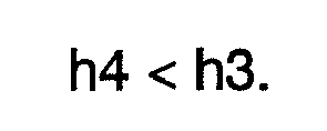
- The above-described
gasket 14 is disposed between thecylinder block 11 and the valve-port assembly 13 so that the outer andinner beads cylinder block 11 as shown in FIG. 2. Thegasket 15 is disposed between the valve-port assembly 13 and therear housing 16 so that the outer andinner beads rear housing 16, as shown in FIG. 2. With thegaskets cylinder block 11, thegaskets rear housing 16. Thebeads gasket 14 and thebeads gasket 49 are pressed against the rear surface of thecylinder block 11 and the front surface of therear housing 16, respectively, under a contact pressure according to the fastening force (axial force) of the bolts B1. - Since the shapes, more specifically, the heights h1 and h2 of the outer and
inner beads gasket 14 are different from each other, the contact pressures of the outer andinner beads outer bead 44 is larger than the height h2 of theinner beads 45, the contact pressure of theouter bead 44 is larger than that of theinner beads 45. Similarly, since the shapes, more specifically, the heights h3 and h4 of the outer andinner beads gasket 15 are different from each other, the contact pressures of the outer andinner beads outer bead 48 is larger than the height h4 of theinner bead 49, the contact pressure of theouter bead 48 is larger than that of theinner bead 49. - The seal structure of the
compressor 10 of the preferred embodiment is provided in such a way that the contact pressures of thegaskets compressor 10 are located adjacent to the outer periphery of each housing component. Thus, in the seal structure of the preferred embodiment, the beads adjacent to the bolts B1 (or theouter beads 44 and 48) have larger height and hence greater contact pressure. Each of the heights h1 through h4 of thebeads compressor 10 of the preferred embodiment, the required contact pressure is larger than that in case of using chlorofluorocarbon as refrigerant. - The following will describe the operation of the
compressor 10 of the preferred embodiment. In thecompressor 10, the refrigerant gas in thesuction chamber 28 is drawn into thecompression chamber 27, compressed in thecompression chamber 28 and discharged into thedischarge chamber 29, as described earlier herein. Thus, the pressures in thecompression chamber 27, thesuction chamber 28 and thedischarge chamber 29 vary during suction and discharge strokes, thereby generating pressure differential among thecompression chamber 27, thesuction chamber 28 and thedischarge chamber 29. For example, during the suction stroke, there is no pressure differential between thecompression chamber 27 and thesuction chamber 28 but a pressure differential is generated between thecompression chamber 27 and thedischarge chamber 29. On the other hand, during the discharge stroke, there is no pressure differential between thecompression camber 27 and thedischarge chamber 29 but the pressure differential is generated between thecompression chamber 27 and thesuction chamber 28. - The
valve plate 17 is bent under the influence of the above pressure variation, thus the contact pressures of thegaskets gaskets gaskets cylinder block 11 and, during the discharge stroke, thegaskets gaskets rear housing 16. The contact pressure of thegaskets inner beads - In the
compressor 10 of the preferred embodiment, the heights h1 and h3 of theouter beads inner beads beads gaskets gaskets - It is noted that since leakage of the refrigerant gas from the refrigerant passage is permissible within the range in which the
compressor 10 can maintain its intended performance, priority may be attached to successful prevention of damage to theinner beads inner beads compressor 10 need to be ensured for preventing the refrigerant gas from leaking out of thecompressor 10, priority may be attached to the airtightness of thecompressor 10 in setting the heights h1 and h3 of theouter beads - According to the preferred embodiment described above, the following advantageous effects are obtained.
- (1) The heights h2 and h4 of the
inner beads outer beads inner beads beads beads gaskets - (2) The heights h1 and h3 of the
beads compressor 10. - (3) The
outer beads beads compressor 10 and, therefore, thebeads cylinder block 11 and therear housing 16 with a contact pressures by the fastening force of the bolts B1 that is enough to ensure the airtightness of thecompressor 10. - (4) When carbon dioxide is used as refrigerant, the working pressure in the
compressor 10 is much higher than that in the case of using chlorofluorocarbon as refrigerant and the pressure differential between high-pressure region and low-pressure region in thecompressor 10 is large, thus making the refrigerant gas easy to leak. Thus, when carbon dioxide is used as refrigerant, thegaskets compressor 10 than the case of using chlorofluorocarbon as refrigerant. In the refrigeration cycle using carbon dioxide as refrigerant in the preferred embodiment, theouter beads compressor 10 while theinner beads compressor 10. - The above preferred embodiment may be modified in various ways as exemplified below.
- In an alternative embodiment, the
beads gaskets - In an alternative embodiment, each of the
gaskets - In an alternative embodiment, the present invention may be applied to a double-headed piston type compressor instead of the single-headed piston type compressor as shown in FIG. 1.
- In an alternative embodiment, the
compressor 10 may be used in a refrigeration cycle of a vehicle air-conditioner in which refrigerant such as chlorofluorocarbon other than carbon dioxide is used. - In the preferred embodiment, the
compressor 10 is of a five-cylinder type. However, the compressor may have cylinder bores the number of which is other than five. - The
inner beads gaskets inner beads gasket 14 should be lower than that for thegasket 15. In thecompressor 10 of the preferred embodiment, the length of the beads of thegasket 14 adjacent to thecylinder block 11 is longer than that of thegasket 15, so that contact pressure of thegasket 14 is dispersed relatively easily. Thus, the contact pressure of one of theinner beads 45 of thegasket 14 is smaller than that of theinner bead 49 of thegasket 15 and, therefore, theinner beads 45 of thegasket 14 are more susceptible to the pressure variation in the compressor. For that reason, thebeads 45 are formed with a height that is smaller than that of thebead 49. - In an alternative embodiment, the bolts for fastening the housing member of the compressor such as bolts B1 may be disposed adjacent to the center of the compressor.
- In an alternative embodiment, the positions of the
suction chamber 28 and thedischarge chamber 29 in therear housing 16 may be reversed. In other words, thedischarge chamber 29 may be formed so as to surround thesuction chamber 28. - Therefore, the present examples and embodiments are to be considered as illustrative and not restrictive, and the invention is not to be limited to the details given herein but may be modified within the scope of the appended claims.
- A piston type compressor comprises a cylinder block having a plurality of cylinder bores, a plurality of pistons disposed in the respective cylinder bores for defining compression chambers in the respective cylinder bores, a housing for defining a suction-pressure region and a discharge-pressure region therein, a valve-port assembly provided between the cylinder block and the housing, and a seal member provided between the cylinder block and the housing. The seal member has a first seal portion for preventing the refrigerant from leaking out of the compressor and a second seal portion for preventing the refrigerant from leaking between adjacent refrigerant passages. Each of the first and second seal portions has a bead. The bead of the second seal portion has a height which is smaller than that of the first seal portion.
Claims (9)
- A piston type compressor (10) comprising:a cylinder block (11) having a plurality of cylinder bores (25);a plurality of pistons (26) disposed in the respective cylinder bores (25) for defining compression chambers (27) in the respective cylinder bores (25);a housing (16) for defining a suction-pressure region (28) and a discharge-pressure region (29) therein;a valve-port assembly (13) provided between the cylinder block (11) and the housing (16), the valve-port assembly (13) having suction ports (30) which connect the suction-pressure region (28) to the respective compression chambers (27) and discharge ports (31) which connect the respective compression chambers (27) to the discharge-pressure region (29), thereby refrigerant passages being provided by the respective compression chambers (27), the suction-pressure region (28), the discharge-pressure region (29), the respective suction ports (30), and the respective discharge ports (31), wherein refrigerant is drawn from the suction-pressure region (28) into the compression chambers (27) through the respective suction ports (30) and discharged from the compression chambers (27) into the discharge-pressure region (29) through the respective discharge ports (31) after compression; anda seal member (14, 15) provided between the cylinder block (11) and the housing (16), wherein the valve-port assembly (13) and the seal member (14, 15) are fastened together by a fastening member (B1),characterized in that the seal member (14, 15) has a first seal portion (44, 48) for preventing the refrigerant from leaking out of the compressor (10) and a second seal portion (45, 49) for preventing the refrigerant from leaking between the adjacent refrigerant passages,
in that each of the first and second seal portions (44, 45, 48, 49) has a bead (44, 45, 48, 49), and
in that the bead (45, 49) of the second seal portion (45, 49) has a height (h2, h4) which is smaller than that of the first seal portion (44, 48). - The piston type compressor (10) according to claim 1, wherein the first seal portion (44, 48) is located along each of outer peripheries of end surfaces of the cylinder block (11) and the housing (16), the second seal portion (45, 49) is located radially inward of the first seal portion (44, 48), and the cylinder block (11), the seal member (14, 15), and the housing (16) are fastened together by the fastening member (B1) which is located adjacent to the outer peripheries of the end surfaces of the cylinder block (11) and the housing (16).
- The piston type compressor (10) according to claim 2, wherein the seal member (14, 15) includes a first seal member (14) which is provided between the cylinder block (11) and the valve-port assembly (13) and a second seal member (15) which is provided between the housing (16) and the valve-port assembly (13), each of the first and second seal members (14, 15) has the first and second seal portions (44, 45, 48, 49), the second seal portion (45) of the first seal member (14) is located so as to surround each of openings of the cylinder bores (25) for preventing the refrigerant from leaking out of each of the compression chambers (27), and the second seal portion (49) of the second seal member (15) is located between the suction-pressure region (28) and the discharge-pressure region (29) for preventing the refrigerant from leaking between the suction-pressure region (28) and the discharge-pressure region (29).
- The piston type compressor (10) according to claim 3, wherein the height (h2) of the bead (45) of the second seal portion (45) of the first seal member (14) is substantially the same as or smaller than that of the second seal portion (49) of the second seal member (15).
- The piston type compressor (10) according to any one of claims 3 and 4, wherein the beads (44, 45) of the first and second seal portions (44, 45) of the first seal member (14) are formed so as to project toward the cylinder block (11).
- The piston type compressor (10) according to any one of claims 3 through 5, wherein the beads (48, 49) of the first and second seal portions (48, 49) of the second seal member (15) are formed so as to project toward the housing (16).
- The piston type compressor (10) according to any one of claims 3 through 6, wherein each of the first and second seal members (14, 15) includes a metal plate (41, 46) having rubber coatings (42a, 42b, 47a, 47b) on both surfaces of the metal plate (41, 46).
- The piston type compressor (10) according to any one of claims 3 through 7, wherein the first seal portion (44) of the first seal member (14) is adjacent to the first seal portion (48) of the second seal member (15).
- The piston type compressor (10) according to any one of claims 1 through 8, wherein the compressor (10) is used in a refrigeration cycle in which carbon dioxide is used as the refrigerant.
Applications Claiming Priority (1)
| Application Number | Priority Date | Filing Date | Title |
|---|---|---|---|
| JP2006243070A JP2008064035A (en) | 2006-09-07 | 2006-09-07 | Piston type compressor |
Publications (2)
| Publication Number | Publication Date |
|---|---|
| EP1898089A2 true EP1898089A2 (en) | 2008-03-12 |
| EP1898089A3 EP1898089A3 (en) | 2008-07-23 |
Family
ID=38723879
Family Applications (1)
| Application Number | Title | Priority Date | Filing Date |
|---|---|---|---|
| EP07114228A Withdrawn EP1898089A3 (en) | 2006-09-07 | 2007-08-13 | Piston type compressor |
Country Status (3)
| Country | Link |
|---|---|
| US (1) | US20080063550A1 (en) |
| EP (1) | EP1898089A3 (en) |
| JP (1) | JP2008064035A (en) |
Families Citing this family (2)
| Publication number | Priority date | Publication date | Assignee | Title |
|---|---|---|---|---|
| DE102006060017B4 (en) * | 2006-12-19 | 2020-10-15 | Robert Bosch Gmbh | Flat seal |
| CN111819378B (en) * | 2018-03-14 | 2022-10-18 | 三菱电机株式会社 | Gaskets and refrigeration cycle devices |
Family Cites Families (7)
| Publication number | Priority date | Publication date | Assignee | Title |
|---|---|---|---|---|
| JPH10196535A (en) * | 1997-01-08 | 1998-07-31 | Toyota Autom Loom Works Ltd | Gasket for compressor |
| JPH11343974A (en) * | 1998-05-29 | 1999-12-14 | Toyota Autom Loom Works Ltd | Reciprocating compressor |
| JP3177841B2 (en) * | 1999-09-08 | 2001-06-18 | 石川ガスケット株式会社 | Cylinder head gasket |
| DE60329332D1 (en) * | 2002-12-26 | 2009-10-29 | Zexel Valeo Climate Contr Corp | SEAL FOR A COMPRESSOR |
| JP2004293421A (en) * | 2003-03-27 | 2004-10-21 | Toyota Industries Corp | Piston type compressor |
| JP2005195139A (en) * | 2004-01-09 | 2005-07-21 | Ishikawa Gasket Co Ltd | Cylinder head gasket |
| JP2005344625A (en) * | 2004-06-03 | 2005-12-15 | Zexel Valeo Climate Control Corp | Compressor |
-
2006
- 2006-09-07 JP JP2006243070A patent/JP2008064035A/en not_active Withdrawn
-
2007
- 2007-08-13 EP EP07114228A patent/EP1898089A3/en not_active Withdrawn
- 2007-08-30 US US11/897,573 patent/US20080063550A1/en not_active Abandoned
Also Published As
| Publication number | Publication date |
|---|---|
| EP1898089A3 (en) | 2008-07-23 |
| US20080063550A1 (en) | 2008-03-13 |
| JP2008064035A (en) | 2008-03-21 |
Similar Documents
| Publication | Publication Date | Title |
|---|---|---|
| EP0961032B1 (en) | A reciprocating type refrigerant compressor with an improved internal sealing unit | |
| US5556261A (en) | Piston type compressor | |
| US6572342B2 (en) | Variable capacity compressor and method of manufacturing | |
| US20080063550A1 (en) | Piston type compressor | |
| US5101555A (en) | Method of assembling a refrigerent compressor | |
| EP2354548A1 (en) | Variable displacement type reciprocating compressor | |
| JP7136003B2 (en) | piston compressor | |
| EP1288497A2 (en) | Sealing mechanism for compressor | |
| US20030025276A1 (en) | Shaft sealing devices, compressors comprising the shaft sealing devices, and methods for sealing a rotational shaft | |
| US20010050464A1 (en) | Housing seal | |
| US6572343B2 (en) | Cylinder block for a piston-type compressor with deformation absorbing gaps | |
| JP2001132629A (en) | Swash plate compressor | |
| JP2002070739A (en) | Reciprocating refrigerant compressor | |
| US6607364B2 (en) | Piston compressor and method of producing the same | |
| JPH09177670A (en) | Piston type compressor | |
| JP2005105975A (en) | Valve structure of compressor | |
| US6499975B2 (en) | Means for sealing the cylinder bore of a variable displacement compressor without using a valve plate | |
| JP2005201336A (en) | Shaft seal device and compressor | |
| EP1795750A1 (en) | Piston compressor | |
| EP1586773B1 (en) | Gasket for compressor | |
| KR101487025B1 (en) | compressor | |
| JP2014125994A (en) | Piston type compressor | |
| JP2002031058A (en) | Reciprocating refrigerant compressor | |
| KR101290633B1 (en) | silling structure of compressor gasket | |
| KR101205218B1 (en) | Compressor |
Legal Events
| Date | Code | Title | Description |
|---|---|---|---|
| PUAI | Public reference made under article 153(3) epc to a published international application that has entered the european phase |
Free format text: ORIGINAL CODE: 0009012 |
|
| 17P | Request for examination filed |
Effective date: 20070813 |
|
| AK | Designated contracting states |
Kind code of ref document: A2 Designated state(s): AT BE BG CH CY CZ DE DK EE ES FI FR GB GR HU IE IS IT LI LT LU LV MC MT NL PL PT RO SE SI SK TR |
|
| AX | Request for extension of the european patent |
Extension state: AL BA HR MK YU |
|
| PUAL | Search report despatched |
Free format text: ORIGINAL CODE: 0009013 |
|
| AK | Designated contracting states |
Kind code of ref document: A3 Designated state(s): AT BE BG CH CY CZ DE DK EE ES FI FR GB GR HU IE IS IT LI LT LU LV MC MT NL PL PT RO SE SI SK TR |
|
| AX | Request for extension of the european patent |
Extension state: AL BA HR MK RS |
|
| AKX | Designation fees paid |
Designated state(s): DE FR IT |
|
| STAA | Information on the status of an ep patent application or granted ep patent |
Free format text: STATUS: THE APPLICATION HAS BEEN WITHDRAWN |
|
| 18W | Application withdrawn |
Effective date: 20091111 |