EP1898053A2 - Singlet welded nozzle hybrid design for a turbine - Google Patents
Singlet welded nozzle hybrid design for a turbine Download PDFInfo
- Publication number
- EP1898053A2 EP1898053A2 EP07114373A EP07114373A EP1898053A2 EP 1898053 A2 EP1898053 A2 EP 1898053A2 EP 07114373 A EP07114373 A EP 07114373A EP 07114373 A EP07114373 A EP 07114373A EP 1898053 A2 EP1898053 A2 EP 1898053A2
- Authority
- EP
- European Patent Office
- Prior art keywords
- turbine
- nozzle
- sidewall
- ring
- welded
- Prior art date
- Legal status (The legal status is an assumption and is not a legal conclusion. Google has not performed a legal analysis and makes no representation as to the accuracy of the status listed.)
- Withdrawn
Links
- 238000013461 design Methods 0.000 title abstract description 11
- 230000001419 dependent effect Effects 0.000 claims 2
- 238000010276 construction Methods 0.000 description 22
- 238000000034 method Methods 0.000 description 10
- 230000000717 retained effect Effects 0.000 description 3
- 230000000712 assembly Effects 0.000 description 2
- 238000000429 assembly Methods 0.000 description 2
- 238000005336 cracking Methods 0.000 description 2
- 230000003068 static effect Effects 0.000 description 2
- 238000003466 welding Methods 0.000 description 2
- 238000013459 approach Methods 0.000 description 1
- 238000006243 chemical reaction Methods 0.000 description 1
- 238000006757 chemical reactions by type Methods 0.000 description 1
- 230000008878 coupling Effects 0.000 description 1
- 238000010168 coupling process Methods 0.000 description 1
- 238000005859 coupling reaction Methods 0.000 description 1
- 238000010894 electron beam technology Methods 0.000 description 1
- 238000003754 machining Methods 0.000 description 1
- 238000004519 manufacturing process Methods 0.000 description 1
- 239000000463 material Substances 0.000 description 1
- 238000012986 modification Methods 0.000 description 1
- 230000004048 modification Effects 0.000 description 1
- 238000012856 packing Methods 0.000 description 1
- 238000005192 partition Methods 0.000 description 1
- 239000007787 solid Substances 0.000 description 1
- 239000007921 spray Substances 0.000 description 1
- 238000011144 upstream manufacturing Methods 0.000 description 1
Images



Classifications
-
- F—MECHANICAL ENGINEERING; LIGHTING; HEATING; WEAPONS; BLASTING
- F01—MACHINES OR ENGINES IN GENERAL; ENGINE PLANTS IN GENERAL; STEAM ENGINES
- F01D—NON-POSITIVE DISPLACEMENT MACHINES OR ENGINES, e.g. STEAM TURBINES
- F01D9/00—Stators
- F01D9/02—Nozzles; Nozzle boxes; Stator blades; Guide conduits, e.g. individual nozzles
-
- F—MECHANICAL ENGINEERING; LIGHTING; HEATING; WEAPONS; BLASTING
- F01—MACHINES OR ENGINES IN GENERAL; ENGINE PLANTS IN GENERAL; STEAM ENGINES
- F01D—NON-POSITIVE DISPLACEMENT MACHINES OR ENGINES, e.g. STEAM TURBINES
- F01D9/00—Stators
- F01D9/02—Nozzles; Nozzle boxes; Stator blades; Guide conduits, e.g. individual nozzles
- F01D9/04—Nozzles; Nozzle boxes; Stator blades; Guide conduits, e.g. individual nozzles forming ring or sector
- F01D9/042—Nozzles; Nozzle boxes; Stator blades; Guide conduits, e.g. individual nozzles forming ring or sector fixing blades to stators
-
- F—MECHANICAL ENGINEERING; LIGHTING; HEATING; WEAPONS; BLASTING
- F01—MACHINES OR ENGINES IN GENERAL; ENGINE PLANTS IN GENERAL; STEAM ENGINES
- F01D—NON-POSITIVE DISPLACEMENT MACHINES OR ENGINES, e.g. STEAM TURBINES
- F01D11/00—Preventing or minimising internal leakage of working-fluid, e.g. between stages
- F01D11/005—Sealing means between non relatively rotating elements
- F01D11/006—Sealing the gap between rotor blades or blades and rotor
-
- F—MECHANICAL ENGINEERING; LIGHTING; HEATING; WEAPONS; BLASTING
- F01—MACHINES OR ENGINES IN GENERAL; ENGINE PLANTS IN GENERAL; STEAM ENGINES
- F01D—NON-POSITIVE DISPLACEMENT MACHINES OR ENGINES, e.g. STEAM TURBINES
- F01D25/00—Component parts, details, or accessories, not provided for in, or of interest apart from, other groups
-
- F—MECHANICAL ENGINEERING; LIGHTING; HEATING; WEAPONS; BLASTING
- F01—MACHINES OR ENGINES IN GENERAL; ENGINE PLANTS IN GENERAL; STEAM ENGINES
- F01D—NON-POSITIVE DISPLACEMENT MACHINES OR ENGINES, e.g. STEAM TURBINES
- F01D9/00—Stators
- F01D9/02—Nozzles; Nozzle boxes; Stator blades; Guide conduits, e.g. individual nozzles
- F01D9/04—Nozzles; Nozzle boxes; Stator blades; Guide conduits, e.g. individual nozzles forming ring or sector
-
- F—MECHANICAL ENGINEERING; LIGHTING; HEATING; WEAPONS; BLASTING
- F01—MACHINES OR ENGINES IN GENERAL; ENGINE PLANTS IN GENERAL; STEAM ENGINES
- F01D—NON-POSITIVE DISPLACEMENT MACHINES OR ENGINES, e.g. STEAM TURBINES
- F01D9/00—Stators
- F01D9/02—Nozzles; Nozzle boxes; Stator blades; Guide conduits, e.g. individual nozzles
- F01D9/04—Nozzles; Nozzle boxes; Stator blades; Guide conduits, e.g. individual nozzles forming ring or sector
- F01D9/041—Nozzles; Nozzle boxes; Stator blades; Guide conduits, e.g. individual nozzles forming ring or sector using blades
-
- F—MECHANICAL ENGINEERING; LIGHTING; HEATING; WEAPONS; BLASTING
- F05—INDEXING SCHEMES RELATING TO ENGINES OR PUMPS IN VARIOUS SUBCLASSES OF CLASSES F01-F04
- F05D—INDEXING SCHEME FOR ASPECTS RELATING TO NON-POSITIVE-DISPLACEMENT MACHINES OR ENGINES, GAS-TURBINES OR JET-PROPULSION PLANTS
- F05D2230/00—Manufacture
- F05D2230/20—Manufacture essentially without removing material
- F05D2230/23—Manufacture essentially without removing material by permanently joining parts together
- F05D2230/232—Manufacture essentially without removing material by permanently joining parts together by welding
-
- F—MECHANICAL ENGINEERING; LIGHTING; HEATING; WEAPONS; BLASTING
- F05—INDEXING SCHEMES RELATING TO ENGINES OR PUMPS IN VARIOUS SUBCLASSES OF CLASSES F01-F04
- F05D—INDEXING SCHEME FOR ASPECTS RELATING TO NON-POSITIVE-DISPLACEMENT MACHINES OR ENGINES, GAS-TURBINES OR JET-PROPULSION PLANTS
- F05D2240/00—Components
- F05D2240/55—Seals
- F05D2240/56—Brush seals
Definitions
- Typical diaphragm stages are constructed using one of two methods.
- the first method is a "band/ring" method that uses an assembly comprised of a plurality of airfoils contained in inner and outer bands and then that banded airfoil assembly is welded into inner (web) and outer rings.
- the second method involves welding airfoils directly to inner and outer rings using a fillet weld at the interface.
- the second method is typically used for larger airfoils, where access for creating the weld is possible.
- the invention provides a singlet welded nozzle hybrid design which inter alia addresses the distortion problem noted above. More particularly, in an example embodiment of the invention a construction is provided wherein a singlet (single airfoil with sidewalls) is seated directly in a radial and circumferential groove of an outer carrier or welded to an outer ring and seated with in a groove of an outer carrier.
- the inner connection is effected with a unique inner sidewall construction.
- the inner sidewalls are mechanically fit and welded to a circumferentially extending ring, or to one another via a small radial weld between inner sidewall endfaces (slashfaces).
- the invention may be embodied in a turbine comprising: a turbine nozzle segment having at least one stator airfoil, an inner sidewall at a radially inner end of the stator airfoil, and an outer sidewall structure at the radially outer end of said stator airfoil, a radially inner surface of the inner sidewall having a circumferential groove defined therein, and a complimentary ring component having a key portion for being received in said circumferential groove, said ring component extending at least part circumferentially of an axis of the turbine to engage an inner sidewall of at least two respectively adjacent nozzle inner sidewalls, wherein the ring component is mechanically secured to the nozzle inner sidewalls.
- the invention may also be embodied in a turbine comprising: a turbine nozzle segment having at least one stator airfoil and including an inner sidewall at a radially inner end of the stator airfoil and an outer sidewall structure at the radially outer end of said stator airfoil; and an outer ring carrier having a radially inwardly open groove; wherein said outer sidewall is configured to slideably engage said groove in a radial direction while being restricted from moving in an axial direction with respect thereto, and the inner sidewall is mechanically coupled to circumferentally adjacent turbine nozzle segments.
- the invention may also be embodied in a turbine comprising: a turbine nozzle segment having at least one stator airfoil and including an inner sidewall at a radially inner end of the stator airfoil and an outer sidewall structure at the radially outer end of said stator airfoil, wherein respectively adjacent nozzle inner sidewall endfaces are welded or braised together.
- FIGURE 1 shows the traditional construction of an impulse type turbine stage that uses partition, bands and rings welded into an assembly. More specifically, this traditional construction uses a diaphragm assembly 10 comprised of a plurality of airfoils 12 contained in inner and outer bands 14, 16 that is welded as at 18, 20, 22, 24 into an inner ring (web) 26 and an outer ring 28.
- Various aspects of the present invention improve the steam path flow path of the stator nozzle (diaphragm) components. This is done with a simplified, determinant, low heat input singlet welded assembly using novel approaches at the inner sidewall connection such as, for example, welded endwalls, low heat input seal welds with mechanical lock, or small ring key welded to inner sidewalls, as described hereinbelow.
- the invention also improves the production cost and cycle by adding features that assist in assembly procedures and that assist in machining fixturing. Further, the invention adds features that reduce the risk of unintended turbine shut down due to hardware weld failure.
- the singlet welded nozzle hybrid design createds a construction that includes a singlet, that is, a single airfoil with respective inner and outer sidewall components.
- the outer sidewall component mechanically fit and then welded to an outer ring carrier.
- connection of the inner sidewall can be achieved in several ways.
- the inner sidewalls of the singlets of the diaphragm can be mechanically fit and welded to either a seal carrier or a small ring, or a small radial weld may be provided between the sidewall endfaces (slashfaces) of circumferentially adjacent singlets.
- This construction is suited primarily to nozzle constructions that are considered reaction-type turbines or "drum” construction turbine sections, characterized by much smaller axial spacing of the stages and a typically increased number of stages.
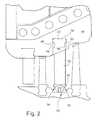
- FIGURE 2 illustrates an example embodiment of the invention wherein a singlet nozzle is slid into a carrier.
- the singlet is comprised of an airfoil 30 and inner and outer sidewalls 32, 34.
- an outer ring carrier 40 configured to slideably engage and radially and axially mechanically lock to outer sidewall 34.
- the outer sidewall 34 is formed to extend radially for being received in a circumferentially extending groove 42 of the outer ring carrier 40.
- the axial end faces of the outer sidewall 34 define first and second grooves 44, 46 that extend in a circumferential direction for receiving corresponding axial protrusions 48, 50 in the ring carrier groove 42.
- the radially inner sidewalls 32 of circumferentially adjacent singlets are coupled.
- an inner ring 52 may be keyed and welded 54, 56 to the construction.
- the keyed inner ring may define a seal carrier.
- the singlet inner sidewalls 32 are welded to each other at their abutting endfaces. Examples the above mentioned assemblies are described in greater detail below with reference to FIGURES 3-6 and 9. These example embodiments are described using some of the same reference numbers (used with reference to FIGURE 2) and with some corresponding reference numbers, but incremented by multiples of 100, as appropriate.
- FIGURE 3 shows an example inner ring 152 disposed to extend at least part circumferentially of the rotor, thereby to couple circumferentially adjacent singlets.
- the inner ring 152 includes a keyed protrusion 158 to engage a corresponding cutout 160 of the inner sidewall 132. More specifically, the singlets are retained axially by the inner ring interfacing with the keyed cutout 160 of the inner sidewall.
- a low heat ring weld (seal weld) 154, 156 is provided between [each] nozzle inner sidewall and the seal carrier.
- This weld is not necessarily meant to be a significant structural weld as the mechanical interlock at the radially outer end (FIGURE 2) will hold the nozzle ends from moving downstream.
- a mechanical design as described allows welds that are very low heat input to cause minimal distortion of the airfoil and steampath surfaces.
- the inner ring 152 is configured to also comprise a seal carrier.
- the seal carrier is very small in design such that it can fit in the small axial and radial spacing typical of drum construction turbine types. This is generally different from the significant real estate required to hold the traditional packing segments at the rotor interface.
- the proposed carrier would facilitate the more advanced seals, i.e., brush seals, shingle type seals or abradable seals.
- This carrier could also be coated with abradable spray prior to assembly and the small seal welds could be machined away for ring removal when a repair (re-coat) is required.
- the inner seal carrier ring 152 carries a brush-type seal structure 162.
- FIGURE 4 shows an alternate inner seal carrier ring 252, having a laminated-type seal 262.
- a keyed interface 258/260 is provided between the seal carrier ring 252 and the inner sidewalls 232.
- low heat ring welds (seal welds) 254, 256 are provided upstream and downstream, as illustrated, to fix the inner seal carrier ring 252 to the inner sidewalls 232 of the respective series of singlet nozzles.
- FIGURE 5 depicts yet another embodiment of the inner carrier ring 352 that is retained axially as in the embodiments of FIGURES 3 and 4 by the interface of the inner seal carrier ring 352 with a keyed cutout 360 of the inner sidewall 332.
- the seal carrier ring 352 has radial bolts 364 into the inner sidewall 332 and airfoil 330 to hold the carrier ring 352 in place with respect to the singlet nozzles.
- the seal carrier ring 352 incorporates a brush-type seal 362, although the illustrated radial fastening could be incorporated in other inner ring structures without departing from this invention.
- FIGURE 6 illustrates yet a further alternate embodiment of the invention wherein a key ring 452 is provided but the seal carrier aspect is omitted in its entirety.
- the nozzle inner sidewalls each have a key notch or groove 460 defined circumferentially therethrough and the key ring 452 is seated in the circumferential groove 460 and welded in place with a low heat ring welds (seal welds) 454, 456.
- the welded key ring thus circumferentially integrates the nozzle singlets with both a welded and mechanical interlock.
- FIGURE 7 shows a further alternate embodiment wherein the singlet nozzle outer sidewall 534 is welded to a solid outer ring 538 is using small axial welds forward and aft 566, 568. The assembly of the singlet nozzle and outer ring is then seated in a corresponding groove 542 of the nozzle carrier 540.
- the nozzle assembly (outer ring 538 and nozzle(s) welded thereto) are not welded to the carrier; the nozzle assembly can move radially in the carrier groove 542.
- the carrier 540 does not have circumferential grooves as is typical in a reaction turbine design that uses slid-in nozzles.
- the mechanical features of the interface between the singlet and the outer ring 538 are used as an assembly and alignment feature and allow for improved reliability and risk abatement.
- the mechanical lock between the ring and nozzle(s) means that, in the even of failure of an airfoil, the rings and nozzles cannot go downstream as there is a mechanical interference preventing the assembly from failing due to the pressure.
- the mechanical lock serves the purpose of a pre-determined and repeatable weld stop. In this regard, the weld beam (assuming an EB weld) would stop when it hits the radial interlock interface.
- a further advantage of the FIGURE 7 embodiment is that the radially outer face of the nozzle outer sidewall is configured as a flat end instead of a more costly circumferentially cut end as in the embodiment of FIGURE 2.
- FIGURE 7 has an inner ring 552 that is mechanically locked and braised or welded to the nozzle inner sidewall 532, as in the embodiments of FIGURES 2-4 and 6, or just mechanically locked to the nozzle, as in the embodiment of FIGURE 5.
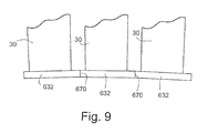
- FIGURES 8 and 9 depict yet a further example embodiment of the invention. More particularly, FIGURE 8 shows a side view of the singlet nozzle welded as in the FIGURE 7 embodiment to an outer ring 538 at the radially outer sidewall 534. On the radially inner end, however, rather than providing a ring seal 552 as in the FIGURE 7 embodiment, the inner sidewall 632 endfaces 670 are welded to each other. Thus, FIGURE 9 shows in an axial view the inner sidewall endwalls/slashfaces respectively welded together. It is envisioned that this weld would be a low heat input weld similar to a butt weld done with a Laser weld or Electron Beam weld (EBW).
- EBW Electron Beam weld
- This interface could also be considered for a braise joint should it be considered more economical.
- the goal of this radial weld is to create the continuous coupling of the inner sidewall. This weld does not necessarily need to be a structural weld but more to cause zero gap between the nozzle segment inner sidewalls (endfaces).
- the typical singlet nozzle outer wall interface is a circumferentially cut end
- the singlet nozzle outer sidewall interface may be machined as a flat end which is less costly than a circumferential cut end.
Landscapes
- Engineering & Computer Science (AREA)
- Mechanical Engineering (AREA)
- General Engineering & Computer Science (AREA)
- Turbine Rotor Nozzle Sealing (AREA)
Abstract
A singlet welded nozzle hybrid design that includes a singlet, that is, a single airfoil with respective inner and outer sidewall components. The outer sidewall component is received in a radial and circumferential groove of an outer carrier. The connection of the inner sidewall can be achieved by mechanically fitting and welded the inner sidewalls to either a seal carrier or a small ring, or a small radial weld may be provided between the sidewall endfaces of circumferentially adjacent singlets.
Description
- Steam turbine designs consist of static nozzle segments that direct the steam flow into rotating buckets that are connected to a rotor. In steam turbines, the nozzle construction is typically called a diaphragm stage. Typical diaphragm stages are constructed using one of two methods. The first method is a "band/ring" method that uses an assembly comprised of a plurality of airfoils contained in inner and outer bands and then that banded airfoil assembly is welded into inner (web) and outer rings. The second method involves welding airfoils directly to inner and outer rings using a fillet weld at the interface. The second method is typically used for larger airfoils, where access for creating the weld is possible. However, there are also limitations to using the band construction on smaller stages. One drawback is the inherent weld distortion of both the flow path and the steam path sidewalls. In this regard, the weld used for the assembly is of considerable size and heat input. This material and heat input causes the flow path to distort and the airfoils often need to be adjusted after welding and stress relief. The result of the distortion is reduced stage efficiency.
- In turbines, thermally induced stresses have always led to cracking in turbine nozzles. Due to the harsh environment, previous field history has shown cracking along the engine axial (chordwise) direction of nozzle airfoils. Should a crack propagate through the entire length of an airfoil, such that the airfoil fails catastrophically, large pieces of the nozzle might dislodge and move downstream into a turbine's rotating hardware. The subsequent damage to the turbine's hardware (both rotating and static) can be both extreme and costly.
- In doublet or triplet nozzle designs (2 or 3 airfoils per nozzle segment, respectively), the increased number of airfoils provides a certain amount of insurance against catastrophic failure through the redundancy of multiple load paths. However, with a singlet design (one airfoil per nozzle segment), if not retained at both platforms, a large section of nozzle (airfoil and/or platform) could be lost into the flowpath if the airfoil were to crack completely in two.
- According to a first aspect, the invention provides a singlet welded nozzle hybrid design which inter alia addresses the distortion problem noted above. More particularly, in an example embodiment of the invention a construction is provided wherein a singlet (single airfoil with sidewalls) is seated directly in a radial and circumferential groove of an outer carrier or welded to an outer ring and seated with in a groove of an outer carrier. The inner connection is effected with a unique inner sidewall construction. In one example embodiment, the inner sidewalls are mechanically fit and welded to a circumferentially extending ring, or to one another via a small radial weld between inner sidewall endfaces (slashfaces).
- Thus, the invention may be embodied in a turbine comprising: a turbine nozzle segment having at least one stator airfoil, an inner sidewall at a radially inner end of the stator airfoil, and an outer sidewall structure at the radially outer end of said stator airfoil, a radially inner surface of the inner sidewall having a circumferential groove defined therein, and a complimentary ring component having a key portion for being received in said circumferential groove, said ring component extending at least part circumferentially of an axis of the turbine to engage an inner sidewall of at least two respectively adjacent nozzle inner sidewalls, wherein the ring component is mechanically secured to the nozzle inner sidewalls.
- The invention may also be embodied in a turbine comprising: a turbine nozzle segment having at least one stator airfoil and including an inner sidewall at a radially inner end of the stator airfoil and an outer sidewall structure at the radially outer end of said stator airfoil; and an outer ring carrier having a radially inwardly open groove; wherein said outer sidewall is configured to slideably engage said groove in a radial direction while being restricted from moving in an axial direction with respect thereto, and the inner sidewall is mechanically coupled to circumferentally adjacent turbine nozzle segments.
- The invention may also be embodied in a turbine comprising: a turbine nozzle segment having at least one stator airfoil and including an inner sidewall at a radially inner end of the stator airfoil and an outer sidewall structure at the radially outer end of said stator airfoil, wherein respectively adjacent nozzle inner sidewall endfaces are welded or braised together.
- Various aspects and embodiments of the present invention will now be described in connection with the accompanying drawings, in which:
- FIGURE 1 is a schematic elevational view of a conventional stage having a nozzle diaphragm formed using the band/ring method;
- FIGURE 2 is a schematic elevational view of a singlet construction according to an example embodiment of the invention;
- FIGURE 3 is a schematic elevational view of the radially inner end of a singlet construction having a brush-type seal according to an example embodiment of the invention;
- FIGURE 4 is a schematic elevational view of the radially inner end of a singlet construction having a laminated-type seal according to another example embodiment of the invention;
- FIGURE 5 is a schematic elevational view of the radially inner end of a singlet construction having a brush type seal according to yet another example embodiment of the invention;
- FIGURE 6 is a schematic elevational view of the radially inner end of a singlet construction according to a further example embodiment of the invention;
- FIGURE 7 is a schematic elevational view of a singlet construction according to another example embodiment of the invention;
- FIGURE 8 is a schematic elevational view of a singlet construction according to yet another example embodiment of the invention; and
- FIGURE 9 is an axial view illustrating adjacent singlet nozzles welded at inner sidewall endfaces according to a further example embodiment of the invention.
- FIGURE 1 shows the traditional construction of an impulse type turbine stage that uses partition, bands and rings welded into an assembly. More specifically, this traditional construction uses a
diaphragm assembly 10 comprised of a plurality ofairfoils 12 contained in inner andouter bands outer ring 28. - As noted above, current methods of construction incorporating single nozzle constructions into rings do not have determinant weld depth, lack assembly alignment features, and also lack retainment features in the event of weld failure. Additionally, one major issue with current methods of diaphragm construction is that they can cause significant flow path distortion. Indeed, traditional singlet nozzle assemblies may use high heat input weld methods that cause undesired flow path distortion.
- Various aspects of the present invention improve the steam path flow path of the stator nozzle (diaphragm) components. This is done with a simplified, determinant, low heat input singlet welded assembly using novel approaches at the inner sidewall connection such as, for example, welded endwalls, low heat input seal welds with mechanical lock, or small ring key welded to inner sidewalls, as described hereinbelow. The invention also improves the production cost and cycle by adding features that assist in assembly procedures and that assist in machining fixturing. Further, the invention adds features that reduce the risk of unintended turbine shut down due to hardware weld failure.
- The singlet welded nozzle hybrid design provided according to example embodiments of the invention creates a construction that includes a singlet, that is, a single airfoil with respective inner and outer sidewall components. The outer sidewall component mechanically fit and then welded to an outer ring carrier.
- The connection of the inner sidewall can be achieved in several ways. As described in various embodiments hereinbelow, the inner sidewalls of the singlets of the diaphragm can be mechanically fit and welded to either a seal carrier or a small ring, or a small radial weld may be provided between the sidewall endfaces (slashfaces) of circumferentially adjacent singlets. This construction is suited primarily to nozzle constructions that are considered reaction-type turbines or "drum" construction turbine sections, characterized by much smaller axial spacing of the stages and a typically increased number of stages.
- FIGURE 2 illustrates an example embodiment of the invention wherein a singlet nozzle is slid into a carrier. The singlet is comprised of an
airfoil 30 and inner andouter sidewalls outer ring carrier 40 configured to slideably engage and radially and axially mechanically lock toouter sidewall 34. To that end, in the illustrated embodiment theouter sidewall 34 is formed to extend radially for being received in a circumferentially extendinggroove 42 of theouter ring carrier 40. In the illustrated example embodiment, the axial end faces of theouter sidewall 34 define first andsecond grooves axial protrusions ring carrier groove 42. There is no weld between the singlet 34 outer platform and thecarrier 40. These nozzles would be slid into the carrier in a circumferential manner and welded only at the inner sidewall to the inner ring, as described in greater detail below. These nozzles can be singlets, doublets, or any other count slid into thegroove 42. If they are doublets or greater, then one could weld the singlet to a partial outer ring (to form a doublet or greater count sub-assembly) that has the carrier interface grooves in it (hybrid design). - According to example embodiments, the radially
inner sidewalls 32 of circumferentially adjacent singlets are coupled. According to certain example embodiments, aninner ring 52 may be keyed and welded 54, 56 to the construction. The keyed inner ring may define a seal carrier. According to another, alternative example embodiment, the singletinner sidewalls 32 are welded to each other at their abutting endfaces. Examples the above mentioned assemblies are described in greater detail below with reference to FIGURES 3-6 and 9. These example embodiments are described using some of the same reference numbers (used with reference to FIGURE 2) and with some corresponding reference numbers, but incremented by multiples of 100, as appropriate. - FIGURE 3 shows an example
inner ring 152 disposed to extend at least part circumferentially of the rotor, thereby to couple circumferentially adjacent singlets. To define an alignment/failsafe interface with theinner sidewalls 132, theinner ring 152 includes akeyed protrusion 158 to engage acorresponding cutout 160 of theinner sidewall 132. More specifically, the singlets are retained axially by the inner ring interfacing with thekeyed cutout 160 of the inner sidewall. As illustrated, a low heat ring weld (seal weld) 154, 156 is provided between [each] nozzle inner sidewall and the seal carrier. This weld is not necessarily meant to be a significant structural weld as the mechanical interlock at the radially outer end (FIGURE 2) will hold the nozzle ends from moving downstream. In this regard, a mechanical design as described allows welds that are very low heat input to cause minimal distortion of the airfoil and steampath surfaces. - In this example embodiment, the
inner ring 152 is configured to also comprise a seal carrier. The seal carrier is very small in design such that it can fit in the small axial and radial spacing typical of drum construction turbine types. This is generally different from the significant real estate required to hold the traditional packing segments at the rotor interface. Thus, the proposed carrier would facilitate the more advanced seals, i.e., brush seals, shingle type seals or abradable seals. This carrier could also be coated with abradable spray prior to assembly and the small seal welds could be machined away for ring removal when a repair (re-coat) is required. In the example embodiment of FIGURE 3, the innerseal carrier ring 152 carries a brush-type seal structure 162. - FIGURE 4 shows an alternate inner
seal carrier ring 252, having a laminated-type seal 262. Again, akeyed interface 258/260 is provided between theseal carrier ring 252 and theinner sidewalls 232. Also, low heat ring welds (seal welds) 254, 256 are provided upstream and downstream, as illustrated, to fix the innerseal carrier ring 252 to theinner sidewalls 232 of the respective series of singlet nozzles. - FIGURE 5 depicts yet another embodiment of the
inner carrier ring 352 that is retained axially as in the embodiments of FIGURES 3 and 4 by the interface of the innerseal carrier ring 352 with akeyed cutout 360 of theinner sidewall 332. As illustrated, in this embodiment, rather than provided ring welds 54, 56 as described with reference to the embodiments of FIGURES 2, 3, and 4, theseal carrier ring 352 hasradial bolts 364 into theinner sidewall 332 andairfoil 330 to hold thecarrier ring 352 in place with respect to the singlet nozzles. In this example, theseal carrier ring 352 incorporates a brush-type seal 362, although the illustrated radial fastening could be incorporated in other inner ring structures without departing from this invention. - FIGURE 6 illustrates yet a further alternate embodiment of the invention wherein a
key ring 452 is provided but the seal carrier aspect is omitted in its entirety. Thus, in this embodiment, the nozzle inner sidewalls each have a key notch or groove 460 defined circumferentially therethrough and thekey ring 452 is seated in thecircumferential groove 460 and welded in place with a low heat ring welds (seal welds) 454, 456. The welded key ring thus circumferentially integrates the nozzle singlets with both a welded and mechanical interlock. - As mentioned above with reference to FIGURE 3, in a first example embodiment, the nozzles, or more specifically, the nozzle outer sidewalls are respectively slid into a carrier thereby providing a radial and axial lock at the outer end of the nozzles. FIGURE 7 shows a further alternate embodiment wherein the singlet nozzle
outer sidewall 534 is welded to a solidouter ring 538 is using small axial welds forward and aft 566, 568. The assembly of the singlet nozzle and outer ring is then seated in acorresponding groove 542 of thenozzle carrier 540. The nozzle assembly (outer ring 538 and nozzle(s) welded thereto) are not welded to the carrier; the nozzle assembly can move radially in thecarrier groove 542. Thus, in this embodiment, thecarrier 540 does not have circumferential grooves as is typical in a reaction turbine design that uses slid-in nozzles. - The mechanical features of the interface between the singlet and the
outer ring 538 are used as an assembly and alignment feature and allow for improved reliability and risk abatement. In this regard, the mechanical lock between the ring and nozzle(s) means that, in the even of failure of an airfoil, the rings and nozzles cannot go downstream as there is a mechanical interference preventing the assembly from failing due to the pressure. Additionally, the mechanical lock serves the purpose of a pre-determined and repeatable weld stop. In this regard, the weld beam (assuming an EB weld) would stop when it hits the radial interlock interface. A further advantage of the FIGURE 7 embodiment is that the radially outer face of the nozzle outer sidewall is configured as a flat end instead of a more costly circumferentially cut end as in the embodiment of FIGURE 2. - The example embodiment of FIGURE 7 has an
inner ring 552 that is mechanically locked and braised or welded to the nozzleinner sidewall 532, as in the embodiments of FIGURES 2-4 and 6, or just mechanically locked to the nozzle, as in the embodiment of FIGURE 5. - FIGURES 8 and 9 depict yet a further example embodiment of the invention. More particularly, FIGURE 8 shows a side view of the singlet nozzle welded as in the FIGURE 7 embodiment to an
outer ring 538 at the radiallyouter sidewall 534. On the radially inner end, however, rather than providing aring seal 552 as in the FIGURE 7 embodiment, theinner sidewall 632endfaces 670 are welded to each other. Thus, FIGURE 9 shows in an axial view the inner sidewall endwalls/slashfaces respectively welded together. It is envisioned that this weld would be a low heat input weld similar to a butt weld done with a Laser weld or Electron Beam weld (EBW). This interface could also be considered for a braise joint should it be considered more economical. The goal of this radial weld is to create the continuous coupling of the inner sidewall. This weld does not necessarily need to be a structural weld but more to cause zero gap between the nozzle segment inner sidewalls (endfaces). - While as mentioned above the typical singlet nozzle outer wall interface is a circumferentially cut end, it is to be understood that as an alternative the singlet nozzle outer sidewall interface may be machined as a flat end which is less costly than a circumferential cut end.
- While the invention has been described in connection with what is presently considered to be the most practical and preferred embodiment, it is to be understood that the invention is not to be limited to the disclosed embodiment, but on the contrary, is intended to cover various modifications and equivalent arrangements included within the spirit and scope of the appended claims.
-
-
diaphragm assembly 10 -
airfoils 12 - inner and
outer bands - welds 18, 20, 22, 24
- inner ring (web) 26
-
outer ring 28 -
airfoil 30 - inner and
outer sidewalls -
outer ring carrier 40 - circumferentially extending
groove 42 - first and
second grooves -
axial protrusions -
inner ring 52 - welds 54, 56
-
inner sidewalls 132 -
inner ring 152 - low heat ring weld (seal weld) 154, 156
-
keyed protrusion 158 -
cutout 160 - brush-
type seal structure 162. -
inner sidewalls 232 - inner
seal carrier ring 252 - low heat ring welds (seal welds) 254, 256
-
keyed interface 258/260 - laminated-
type seal 262 -
airfoil 330 -
inner sidewall 332 -
inner carrier ring 352 -
keyed cutout 360 - brush-
type seal 362 -
radial bolts 364 -
key ring 452 - low heat ring welds (seal welds) 454, 456
- key notch or
groove 460 -
inner sidewall 532 -
outer sidewall 534 -
outer ring 538 -
nozzle carrier 540 - groove 542
-
inner ring 552 -
axial welds -
inner sidewall 632 -
endfaces 670
Claims (10)
- A turbine comprising:a turbine nozzle segment having at least one stator airfoil (30) and including an inner sidewall (32,132,232,332,432,532,632) at a radially inner end of the stator airfoil andan outer sidewall structure (34,534) at the radially outer end of said stator airfoil; andan outer ring carrier (40,540) having a radially inwardly open groove (42,542); whereinsaid outer sidewall (34,534) is configured to engage said groove (42,542) in at least one of a circumferential and a radial direction while being restricted from moving in an axial direction with respect thereto, andthe inner sidewall (32,132,232,332,432,532,632) is mechanically coupled (52,152,252,352,452,552,670) to circumferentally adjacent turbine nozzle segments.
- A turbine as in claim 1, wherein a radially inner surface of the inner sidewall (32),132,232) has a circumferential groove (160,260,360,460) defined therein, and at least a portion (158,258) of a complimentary ring component (52,152,252,352,452,552),is received in said circumferential groove, said ring component extending at least part circumferentially of an axis of the turbine to engage an inner sidewall of at least two respectively adjacent nozzle inner sidewalls, wherein the ring component is mechanically secured (54,56,154,156,254,256,364,454,456) to the nozzle inner sidewalls.
- A turbine as in claim 2, wherein the ring component is welded (54,56,154,156,254,256,454,456) to the nozzle inner sidewalls.
- A turbine as in claim 2 or claim 3, wherein said ring component comprises a seal carrier (52,152,252,352,552).
- A turbine as in claim 4, wherein said seal carrier is a brush-type seal carrier (152,352).
- A turbine as in claim 4, wherein said seal carrier is a laminated-type seal carrier (252).
- A turbine as in claim 4 or any claim dependent thereon, wherein said seal (52,152,252) is welded (54,56,154,156,254,256) to said nozzle inner sidewall.
- A turbine as in claim 2 or any claim dependent thereon, wherein a radial bolt (364) is disposed to extend through said ring component (352) and into said nozzle inner sidewall (332).
- A turbine as in any preceding claim, wherein said outer sidewall (534) is welded to an outer ring (538) that is received in said groove with said outer sidewall.
- A turbine as in any preceding claim, respectively adjacent nozzle inner sidewall (632) endfaces of said circumferentally adjacent turbine nozzle segments are welded or braised (670) together.
Applications Claiming Priority (1)
| Application Number | Priority Date | Filing Date | Title |
|---|---|---|---|
| US11/508,170 US20080050222A1 (en) | 2006-08-23 | 2006-08-23 | Singlet welded nozzle hybrid design for a turbine |
Publications (1)
| Publication Number | Publication Date |
|---|---|
| EP1898053A2 true EP1898053A2 (en) | 2008-03-12 |
Family
ID=38457865
Family Applications (1)
| Application Number | Title | Priority Date | Filing Date |
|---|---|---|---|
| EP07114373A Withdrawn EP1898053A2 (en) | 2006-08-23 | 2007-08-15 | Singlet welded nozzle hybrid design for a turbine |
Country Status (5)
| Country | Link |
|---|---|
| US (1) | US20080050222A1 (en) |
| EP (1) | EP1898053A2 (en) |
| JP (1) | JP2008051105A (en) |
| KR (1) | KR20080018118A (en) |
| CN (1) | CN101131100A (en) |
Cited By (4)
| Publication number | Priority date | Publication date | Assignee | Title |
|---|---|---|---|---|
| EP2348194A3 (en) * | 2010-01-25 | 2013-05-22 | Rolls-Royce plc | Sealing arrangement for a gas turbine engine |
| US8562292B2 (en) | 2010-12-02 | 2013-10-22 | General Electric Company | Steam turbine singlet interface for margin stage nozzles with pinned or bolted inner ring |
| US8684697B2 (en) | 2010-12-13 | 2014-04-01 | General Electric Company | Steam turbine singlet nozzle design for breech loaded assembly |
| US10436047B2 (en) | 2015-08-18 | 2019-10-08 | General Electric Company | Method for repair of a diaphragm of a rotary machine |
Families Citing this family (2)
| Publication number | Priority date | Publication date | Assignee | Title |
|---|---|---|---|---|
| US8070429B2 (en) * | 2009-03-11 | 2011-12-06 | General Electric Company | Turbine singlet nozzle assembly with mechanical and weld fabrication |
| US9011078B2 (en) * | 2012-01-09 | 2015-04-21 | General Electric Company | Turbine vane seal carrier with slots for cooling and assembly |
Family Cites Families (12)
| Publication number | Priority date | Publication date | Assignee | Title |
|---|---|---|---|---|
| US1998951A (en) * | 1933-11-15 | 1935-04-23 | Gen Electric | Nozzle diaphragm |
| US3529905A (en) * | 1966-12-12 | 1970-09-22 | Gen Motors Corp | Cellular metal and seal |
| DE1551193A1 (en) * | 1967-05-16 | 1970-03-12 | Licentia Gmbh | Quick start turbine |
| US3501246A (en) * | 1967-12-29 | 1970-03-17 | Westinghouse Electric Corp | Axial fluid-flow machine |
| US4889470A (en) * | 1988-08-01 | 1989-12-26 | Westinghouse Electric Corp. | Compressor diaphragm assembly |
| US5622475A (en) * | 1994-08-30 | 1997-04-22 | General Electric Company | Double rabbet rotor blade retention assembly |
| US5584654A (en) * | 1995-12-22 | 1996-12-17 | General Electric Company | Gas turbine engine fan stator |
| JP3477347B2 (en) * | 1997-07-30 | 2003-12-10 | 三菱重工業株式会社 | Gas turbine interstage seal device |
| JP4040922B2 (en) * | 2001-07-19 | 2008-01-30 | 株式会社東芝 | Assembly type nozzle diaphragm and its assembly method |
| US6896482B2 (en) * | 2003-09-03 | 2005-05-24 | General Electric Company | Expanding sealing strips for steam turbines |
| US7160078B2 (en) * | 2004-09-23 | 2007-01-09 | General Electric Company | Mechanical solution for rail retention of turbine nozzles |
| US7287956B2 (en) * | 2004-12-22 | 2007-10-30 | General Electric Company | Removable abradable seal carriers for sealing between rotary and stationary turbine components |
-
2006
- 2006-08-23 US US11/508,170 patent/US20080050222A1/en not_active Abandoned
-
2007
- 2007-08-15 EP EP07114373A patent/EP1898053A2/en not_active Withdrawn
- 2007-08-21 KR KR1020070083801A patent/KR20080018118A/en not_active Withdrawn
- 2007-08-22 JP JP2007215703A patent/JP2008051105A/en not_active Withdrawn
- 2007-08-23 CN CNA2007101427502A patent/CN101131100A/en active Pending
Cited By (4)
| Publication number | Priority date | Publication date | Assignee | Title |
|---|---|---|---|---|
| EP2348194A3 (en) * | 2010-01-25 | 2013-05-22 | Rolls-Royce plc | Sealing arrangement for a gas turbine engine |
| US8562292B2 (en) | 2010-12-02 | 2013-10-22 | General Electric Company | Steam turbine singlet interface for margin stage nozzles with pinned or bolted inner ring |
| US8684697B2 (en) | 2010-12-13 | 2014-04-01 | General Electric Company | Steam turbine singlet nozzle design for breech loaded assembly |
| US10436047B2 (en) | 2015-08-18 | 2019-10-08 | General Electric Company | Method for repair of a diaphragm of a rotary machine |
Also Published As
| Publication number | Publication date |
|---|---|
| JP2008051105A (en) | 2008-03-06 |
| CN101131100A (en) | 2008-02-27 |
| US20080050222A1 (en) | 2008-02-28 |
| KR20080018118A (en) | 2008-02-27 |
Similar Documents
| Publication | Publication Date | Title |
|---|---|---|
| JP4918263B2 (en) | Stator blade ring of axial compressor | |
| US7470109B2 (en) | Machine tooled diaphragm partitions and nozzles | |
| EP1808577B1 (en) | A welded nozzle assembly for a steam turbine | |
| US10190434B2 (en) | Turbine shroud with locating inserts | |
| US20090191050A1 (en) | Sealing band having bendable tang with anti-rotation in a turbine and associated methods | |
| US20170051619A1 (en) | Cmc nozzles with split endwalls for gas turbine engines | |
| US7090466B2 (en) | Methods and apparatus for assembling gas turbine engine rotor assemblies | |
| EP1898053A2 (en) | Singlet welded nozzle hybrid design for a turbine | |
| US20090047126A1 (en) | Integrated compressor vane casing | |
| US9009965B2 (en) | Method to center locate cutter teeth on shrouded turbine blades | |
| US7618234B2 (en) | Hook ring segment for a compressor vane | |
| US20160069202A1 (en) | Gas turbine rotor sealing band arrangement having a friction welded pin element | |
| EP2374994A2 (en) | Attachment assemblies between turbine rotor discs and methods of attaching turbine rotor discs | |
| US7713024B2 (en) | Bling nozzle/carrier interface design for a steam turbine | |
| EP3244015B1 (en) | Stator vane shiplap seal assembly | |
| KR100228931B1 (en) | Reheating tub in double-flow steam turbines | |
| US6644924B1 (en) | Covers for turbine buckets and methods of assembly | |
| US12163431B2 (en) | Dynamic seal for a turbomachine comprising a multi-layer abradable part | |
| EP3047130B1 (en) | A gas turbine seal assembly comprising splined honeycomb seals | |
| US6877956B2 (en) | Methods and apparatus for integral radial leakage seal | |
| US10563528B2 (en) | Turbine vane with ceramic matrix composite airfoil | |
| CA2921257A1 (en) | Bucket mounted multi-stage turbine interstage seal and method of assembly | |
| CN106194276A (en) | Compressor Systems and Airfoil Assemblies | |
| US20260036058A1 (en) | Turbine shroud assemblies with retainer features for blocking seal migration | |
| WO2024171723A1 (en) | Repair method, and method for manufacturing combustion cylinder |
Legal Events
| Date | Code | Title | Description |
|---|---|---|---|
| PUAI | Public reference made under article 153(3) epc to a published international application that has entered the european phase |
Free format text: ORIGINAL CODE: 0009012 |
|
| AK | Designated contracting states |
Kind code of ref document: A2 Designated state(s): AT BE BG CH CY CZ DE DK EE ES FI FR GB GR HU IE IS IT LI LT LU LV MC MT NL PL PT RO SE SI SK TR |
|
| AX | Request for extension of the european patent |
Extension state: AL BA HR MK YU |
|
| STAA | Information on the status of an ep patent application or granted ep patent |
Free format text: STATUS: THE APPLICATION IS DEEMED TO BE WITHDRAWN |
|
| 18D | Application deemed to be withdrawn |
Effective date: 20110301 |