EP1898051A2 - Gas turbine airfoil with leading edge cooling - Google Patents
Gas turbine airfoil with leading edge cooling Download PDFInfo
- Publication number
- EP1898051A2 EP1898051A2 EP07112814A EP07112814A EP1898051A2 EP 1898051 A2 EP1898051 A2 EP 1898051A2 EP 07112814 A EP07112814 A EP 07112814A EP 07112814 A EP07112814 A EP 07112814A EP 1898051 A2 EP1898051 A2 EP 1898051A2
- Authority
- EP
- European Patent Office
- Prior art keywords
- cooling
- airfoil
- axis
- along
- leading edge
- Prior art date
- Legal status (The legal status is an assumption and is not a legal conclusion. Google has not performed a legal analysis and makes no representation as to the accuracy of the status listed.)
- Granted
Links
Images


Classifications
-
- F—MECHANICAL ENGINEERING; LIGHTING; HEATING; WEAPONS; BLASTING
- F01—MACHINES OR ENGINES IN GENERAL; ENGINE PLANTS IN GENERAL; STEAM ENGINES
- F01D—NON-POSITIVE DISPLACEMENT MACHINES OR ENGINES, e.g. STEAM TURBINES
- F01D5/00—Blades; Blade-carrying members; Heating, heat-insulating, cooling or antivibration means on the blades or the members
- F01D5/12—Blades
- F01D5/14—Form or construction
- F01D5/18—Hollow blades, i.e. blades with cooling or heating channels or cavities; Heating, heat-insulating or cooling means on blades
- F01D5/186—Film cooling
-
- F—MECHANICAL ENGINEERING; LIGHTING; HEATING; WEAPONS; BLASTING
- F05—INDEXING SCHEMES RELATING TO ENGINES OR PUMPS IN VARIOUS SUBCLASSES OF CLASSES F01-F04
- F05D—INDEXING SCHEME FOR ASPECTS RELATING TO NON-POSITIVE-DISPLACEMENT MACHINES OR ENGINES, GAS-TURBINES OR JET-PROPULSION PLANTS
- F05D2240/00—Components
- F05D2240/10—Stators
- F05D2240/12—Fluid guiding means, e.g. vanes
- F05D2240/121—Fluid guiding means, e.g. vanes related to the leading edge of a stator vane
-
- F—MECHANICAL ENGINEERING; LIGHTING; HEATING; WEAPONS; BLASTING
- F05—INDEXING SCHEMES RELATING TO ENGINES OR PUMPS IN VARIOUS SUBCLASSES OF CLASSES F01-F04
- F05D—INDEXING SCHEME FOR ASPECTS RELATING TO NON-POSITIVE-DISPLACEMENT MACHINES OR ENGINES, GAS-TURBINES OR JET-PROPULSION PLANTS
- F05D2240/00—Components
- F05D2240/20—Rotors
- F05D2240/30—Characteristics of rotor blades, i.e. of any element transforming dynamic fluid energy to or from rotational energy and being attached to a rotor
- F05D2240/303—Characteristics of rotor blades, i.e. of any element transforming dynamic fluid energy to or from rotational energy and being attached to a rotor related to the leading edge of a rotor blade
-
- F—MECHANICAL ENGINEERING; LIGHTING; HEATING; WEAPONS; BLASTING
- F05—INDEXING SCHEMES RELATING TO ENGINES OR PUMPS IN VARIOUS SUBCLASSES OF CLASSES F01-F04
- F05D—INDEXING SCHEME FOR ASPECTS RELATING TO NON-POSITIVE-DISPLACEMENT MACHINES OR ENGINES, GAS-TURBINES OR JET-PROPULSION PLANTS
- F05D2250/00—Geometry
- F05D2250/30—Arrangement of components
- F05D2250/31—Arrangement of components according to the direction of their main axis or their axis of rotation
- F05D2250/314—Arrangement of components according to the direction of their main axis or their axis of rotation the axes being inclined in relation to each other
-
- Y—GENERAL TAGGING OF NEW TECHNOLOGICAL DEVELOPMENTS; GENERAL TAGGING OF CROSS-SECTIONAL TECHNOLOGIES SPANNING OVER SEVERAL SECTIONS OF THE IPC; TECHNICAL SUBJECTS COVERED BY FORMER USPC CROSS-REFERENCE ART COLLECTIONS [XRACs] AND DIGESTS
- Y10—TECHNICAL SUBJECTS COVERED BY FORMER USPC
- Y10T—TECHNICAL SUBJECTS COVERED BY FORMER US CLASSIFICATION
- Y10T29/00—Metal working
- Y10T29/49—Method of mechanical manufacture
- Y10T29/49316—Impeller making
- Y10T29/49336—Blade making
- Y10T29/49339—Hollow blade
- Y10T29/49341—Hollow blade with cooling passage
Definitions
- This invention pertains to a gas turbine airfoil and in particular to a cooling construction for its leading edge.
- Airfoils of gas turbines, turbine rotor blades and stator vanes require extensive cooling in order to keep the metal temperature below a certain allowable level and prevent damage due to overheating.
- airfoils are designed with hollow spaces and a plurality of passages and cavities for cooling fluid to flow through.
- the cooling fluid is typically air bled from the compressor having a higher pressure and lower temperature compared to the gas travelling through the turbine. The higher pressure forces the air through the cavities and passages as it transports the heat away from the airfoil walls.
- the cooling construction further usually comprises film cooling holes leading from the hollow spaces within the airfoil to the external surfaces of the leading and trailing edge as well as to the suction and pressure sidewalls.
- the leading edge of a turbine blade is one of the areas that faces the hottest gas flow conditions, and is thus one of the most critical areas to be cooled. It also has the particularity to have a strong surface curvature and thus a highly accelerated flow from each side of the stagnation line.
- cooling the leading edge with an internal cooling passage is usually not sufficient, requiring additional rows of holes drilled into the leading edge to pick-up some heat directly through the holes and to provide a layer of coolant film on the external surface.
- the interaction of the coolant flow ejected from theses rows of holes and the main hot gas flow can be difficult to predict, especially in situations where the stagnation line position can be uncertain due to changes of incidence angles. For this reason extensive studies have been performed on several leading edge film cooling configurations, including cylinders and blunt body models that simulate the leading edge of a turbine airfoil.
- the film cooling holes extending from cooling passages within the airfoil to the leading edge are positioned at a large angle to the leading edge surface and are designed with a small length to diameter ratio.
- the angle between the cooling hole axis and the leading edge surface is significantly greater than 20 deg. and the ratio of the cooling hole length to the cooling hole diameter is about 10, typically less than 15.
- Such holes are drilled by a electro-discharge machining process and more recently by a laser drilling process.
- Such film cooling holes provide a good convective cooling of the leading edge of the airfoil due to the cumulative convective cooling area of all the film cooling holes together that are positioned between the root and the tip of the airfoil leading edge.
- the cooling air that exits the film cooling holes provides further cooling by means of a film that passes along the surface of the airfoil leading edge.
- the short length to diameter ratio of the film cooling holes and the large angle between the hole axes and the leading edge surface can lead to the formation of vortices about the exit holes. This results in a high penetration of the cooling film away from the surface of the airfoil and in a decrease of the film cooling effectiveness about the leading edge of the airfoil.
- One way to provide better film cooling of the airfoil surface is to orient the film cooling holes at a shallower angle with respect to the leading edge surface. This would decrease the tendency of vortex formation. However, a more shallow angle results in a larger length to diameter ratio of the film cooling hole, which exceeds the capabilities of today's laser drilling machines.
- EP 0 924 384 discloses an airfoil with a cooling construction of the leading edge of an airfoil that provides improved film cooling of the surface.
- the disclosed airfoil comprises a trench that extends along the leading edge and from the root to the tip of the airfoil.
- the apertures of the film cooling holes are positioned within this trench in a continuous straight row. The cooling air bleeds to both sides of these apertures and provides a uniform cooling film downstream and to both sides of the airfoil.
- US 5779437 provides a cooling system for the showerhead region in which there is a multitude of passages wherein each passage has a radial component and a downstream component relative to the leading edge axis, and the outlet of each passage has a diffuser area formed by conical machining, wherein the diffuser area is recessed in the wall portion downstream of the passage.
- EP 1 645 721 discloses an airfoil comprising several film cooling holes at the leading edge with exit ports.
- the film cooling holes have a sidewall that is diffused in the direction of the tip of the airfoil at least over a part of the film cooling hole. Furthermore, the film cooling holes each have flare-like contour near the outer surface of the leading edge. The film cooling holes are stated to provide an improved film cooling effectiveness due to reduced formation of vortices and decreased penetration depth of the cooling air film.
- One objective of the present invention is therefore to provide an improved cooling structure for the leading edge of a turbine airfoil.
- the present invention relates to the improvement of a gas turbine airfoil with a pressure sidewall and a suction sidewall, extending from a root to a tip and from a leading edge region to a trailing edge and comprising at least one cooling passage between the pressure sidewall and the suction sidewall for cooling air to pass through and cool the airfoil from within.
- one or several of the cooling passages extend along the leading edge of the airfoil and several film cooling holes extend from the internal cooling passages along the leading edge region to the outer surface of the leading edge region, wherein the film cooling holes each have a shape that is diffused in a radial outward direction of the leading edge of the airfoil at least over a part of the length of the film cooling hole.
- cooling holes the exit of which is asymmetrically diffused in two different directions.
- the cooling holes comprise a principal axis (usually defined by a cylindrical section of the cooling holes which is located in the entry region, i.e. adjacent to the internal cooling passage), and in that the shape is asymmetrically diffused on the one hand in a radial outward direction tilted away from the principal axis along a forward inclination axis, and on the other hand in a second, lateral direction (being different from the forward inclination direction) tilted away from the principal axis along a lateral inclination axis.
- the key feature of the invention is therefore the fact that in contrast to the state-of-the-art, where either the cooling holes are simply conically widening at their exit, or are selectively conically widening in a radial direction only, according to the invention specifically two (or more) directions are defined in which the opening of the cooling holes is widening.
- the widening in the radial direction which leads to the asymmetry along the radial direction as defined by the forward inclination axis.
- there is the lateral widening usually perpendicular to the radial direction and downstream of the hot gas flow, so away from the stagnation line, as defined by the lateral inclination axis.
- film cooling is provided downstream of the cooling hole in a radial direction, and additionally in the direction of the hot gas which impinges onto the shower head region, i.e. onto the leading edge region, and travels to the trailing edge, so in the lateral direction, which is essentially perpendicular to the stagnation line along the leading edge.
- a first preferred embodiment of the cooling holes according to present invention is characterised in that the shape of the cooling holes is diffused essentially cylindrically (or slightly conically) in the radial outward direction along the forward inclination axis.
- the shape is diffused essentially cylindrically (or slightly conically) in the second, lateral direction along a lateral inclination axis.
- the shape or diffusion portion surface between the two cylindrical diffusion sections is smoothed, e.g. via connecting surfaces which are preferably essentially tangential to both cylindrical diffusion sections along the two different directions.
- a further preferred embodiment is characterised in that the principal axis is radially inclined by 50-70° from the horizontal plane, so from the surface of the airfoil at the location of the cooling hole. So the angle ⁇ between the plane and this principal axis is an acute angle in the range of 20-40°. It is also possible to incline the principal axis along a downstream (or opposite) component relative to the leading edge, e.g. with an inclination angle of 85-105° to the normal to the horizontal plane in a direction essentially perpendicular to the radial direction, preferably however the principal axis is only radially inclined and parallel to the stagnation line.
- the forward inclination axis is tilted from the principal axis towards the radial direction of the airfoil (so in a radial direction and towards the surface of the airfoil), and in that the angle ⁇ between the principal axis and the forward inclination axis is in the range of 5-20°, preferably in the range of 5-15°. If, as preferred, the principal axis encloses an angle ⁇ with the plane of about 30°, the angle between the forward inclination axis and the plane is in the range of 10-25°.
- a further preferred embodiment is characterised in that the lateral inclination axis is tilted from the principal axis along a direction essentially perpendicular to a stagnation line on the leading-edge and in the downstream direction, and in that the angle ⁇ between the principal axis and the lateral inclination axis is in the range of 5-20°, preferably in the range of 5-15°. If, as preferred, the principal axis is not inclined along a downstream component, this means that the lateral inclination axis encloses an angle in the range of 70-85° with the plane of the airfoil at the exit region of the cooling hole in the downstream direction.
- one row of cooling holes is located on the pressure side of the stagnation line and a second row of cooling holes is located on the suction side of the stagnation line.
- these two rows are equally distanced on both sides from the stagnation line. It could be shown that a particularly efficient cooling can be achieved if in each of the rows at least the plurality of the holes, preferably all of the holes are equally distanced from the stagnation line. It is furthermore preferred if the cooling holes in the two rows are arranged in a staggered manner along the radial direction, wherein preferably they are staggered by one hole pitch from each other.
- each row of holes is located at least 3 hole diameters (the hole diameter generally defined as the whole diameter of the cylindrical section of the cooling hole) distanced from the stagnation line, preferably 3-3.5 hole diameters distanced from the stagnation line.
- the cooling holes are distanced by at least 1 hole diameters, preferably in the range of 4 - 6 hole diameters (distancing normally calculated as indicated with y in Figure 3, hole diameter normally taken as the diameter in the cylindrical or in the diffused area of the hole).
- the cooling holes comprise a cylindrical section at the entry portion facing the cooling passage. It is furthermore preferred, that the diameters of the two cylindrical diffusions is equal or in the range of the diameter of the cylindrical section of the entry portion.
- the cooling holes have a hole length to diameter ratio ranging from 2 - 6, wherein the diameter is taken as the diameter in the cylindrical or in the diffused area of the hole.
- a further preferred embodiment is characterised in that the ratio of the cross-section in the widening portion of the holes to the cross-section in the cylindrical section of the holes is in the range of 1.5-2.45, preferably in the range of 1.8-2.0. Typically it is around 1.95.
- the lateral inclination can be located at different positions along the forward direction of the cooling role. As a matter of fact, it can be located either at the two extremes given by the forward edge or the backward edge of the hole, or in the range between these extremes. So according to a further preferred embodiment, the lateral inclination axis is located at or between a forward edge and a backward edge of the exit portion of the hole and preferably tilted from the principal axis along a direction such that essentially at the transition of the cylindrical and the widening portion the axis of the cylindrical section and the axis of the inclination cross.
- cooling hole structures can be formed by conventional drilling methods including electro-discharge machining, but preferably by laser drilling methods.
- the machining process can be carried out in that first a cylindrical, fully penetrating hole is machined defining the principal axis and thus, if present, the cylindrical section. Subsequently, two additional cylindrical machining steps are carried out along the lateral inclination axis and along the forward inclination axis. In the last step, the surface of the diffusion region of the cooling holes is smoothed.
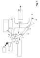
- figure 1 shows a cut essentially in a plane perpendicular to the radial direction of the row of gas turbine blades through the leading edge or shower head region of a gas turbine airfoil 6.
- the gas turbine airfoil 6 is given as a hollow body defined by a pressure side wall 15 and a suction sidewall 16, which at the leading edge converge in the shower head region or leading edge region, and which at the trailing edge 29 (not displayed) also converge.
- cooling air passages there is provided a plurality of cooling air passages, and in this specific embodiment there is provided one radial cooling air cooling air passage 3 in the leading edge region.
- cooling holes In the very region of the leading edge, there is provided two rows of cooling holes. On the one hand on the pressure side there is provided a first row of cooling holes 1, and on the suction side there is provided a second row of cooling holes 2.
- the cooling air which usually travels through the cooling air passage 3 in a radial direction enters these cooling holes 1, 2 via the corresponding entry portions 13 and 14, penetrates through the cooling holes and exits these via the exit portions 11 and 12 in the form of cooling air discharges 9 and 10, respectively.
- cooling air discharge 9, 10 indeed forms a film which remains on the outer surface of the airfoil 6 and which is generated with as little vortices as possible.
- the cooling hole 1,2 comprises, in the region of the exit portion 12, 13, a cylindrical portion 18.
- This cylindrical portion 18 defines the principal axis 17 of the cooling hole 1, 2.
- this principle axis 17 is inclined with respect to the normal of the plane of the sidewall in this leading edge region. It is inclined from the normal to this plane in a radial direction, and this by an angle 90° - ⁇ , as indicated in figure 2.
- the angle ⁇ is ideally in the range of approximately 25 - 35°.
- This radial arrangement of the principal axis 17 on the one hand makes sure that the cooling gas flow as indicated with the arrow in the cooling air passage smoothly enters the cooling hole via the exit portion 11, 12. On the other hand it assures basically a vortex free formation of the film for film cooling, if used in conjunction with the further widening portion 19 as to be described below.
- This widening portion 19 on the one hand comprises a first widening along a forward inclination axis, as indicated with the reference no. 20.
- This forward inclination axis is even more tilted in the radial direction than the principal axis 17.
- both axes 17 and 20 are aligned in a radial plane, and the principal axis 17 and the forward inclination axis enclose an angle ⁇ , which is typically in the range of 10°.
- This widening portion, as defined by this forward inclination axis 20, is actually an essentially cylindrical bore with the axis 20 penetrating until the cylindrical portion 18 starts.
- this lateral inclination can be located at different positions. So talking in a process mode it is for example possible to first machine the cylindrical section along the axis 17, and to then drill the forward inclination of along the axis 20. This then leads to a hole which has a forward edge A and a backward edge B. The lateral inclination can now either be drilled by starting at the forward edge A or by starting at the backward edge B, or in principle in the full range between these two positions. The situation as displayed in figure 2 is the one in which the lateral drilling was carried out starting from position B, so at the backward edge B.
- This highly asymmetric outline and the double-axis asymmetric widening of the widening portion 19 provides a highly efficient cooling film formation, essentially without vortexes and with a broad covering of the area downstream of the cooling hole 1, 2.
- drilling is carried out with a conventional cylindrical drilling tool along the principal axis with a diameter corresponding to the diameter of the desired cylindrical portion, and to produce a fully penetrating cooling hole.
- two subsequent steps preferably using the same drilling tool, first the forward inclination is produced by drilling along the forward inclination axis 20, and then the lateral inclination is produced by drilling a second time along the lateral inclination axis 21. Subsequently one can, if at all necessary, smoothen the internal surface of the widening portion 19, for example by tangentially joining the cylindrical portions generated in the triple boring process.
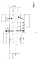
- Cooling holes as displayed in figure 2 can be arranged along the leading edge as displayed in figure 3.
- Figure 3 is actually a view along the arrow A as given in figure 1, and it represents an unrolled view onto the surface of the airfoil.
- the hot air which basically impinges onto the surface along a direction as also given by the arrow A in figure 1, is split into two hot gas flows 27 and 28, which travel along the pressure side and the suction side, respectively.
- the separation into these two flows essentially takes place along the so-called stagnation line 25, which is indicated in a dashed manner in figure 3.
- the cooling holes are arranged in two rows which are located symmetrically on both sides of the stagnation line 25.
- the cooling holes are distanced from the stagnation line 25 approximately by 3.25 times the hole diameters (taken as the diameter C as defined above), and the two rows are arranged in a staggered manner, wherein the cooling holes are radially staggered by one hole pitch from each other.
- Figure 3 shows a situation, in which the forward inclination angle ⁇ is 10°, and in which the lateral inclination ⁇ is also 10°.
- the holes are spaced in the radial direction by the distance y, which is typically in the range of 4 - 6 hole diameters C.
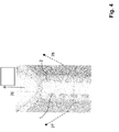
- Figure 4 shows a perspective view onto the surface of such a leading edge, clearly indicating the highly asymmetric outline 22 of the widening portion 19 of the cooling holes 1,2.
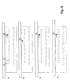
- Figure 5 shows four different possibilities for arranging the two rows of cooling holes on the leading edge.
- Figures 5 a) and b) both show a situation in which the angle ⁇ is 10° and also ⁇ is 10°. The difference between these two embodiments is that in figure 5a the lateral inclination was drilled or provided at the backside edge B of the hole. This leads to a widening rather in the backside area.
- Figures 5 c) and d) indicate a situation, in which the forward inclination angle ⁇ is 10°. However, in this case the lateral inclination angle ⁇ is wider, leading to broader outlines 22 of the cooling holes. Again, the difference between these two embodiments is that in figure 5c the lateral inclination was drilled or provided at the backside edge B of the hole. This leads to a widening rather in the backside area. In contrast to that, in figure 5d the lateral inclination was drilled at the forward edge A of the hole. This leads to a widening in the forward direction of the hole. Also here intermediate positioning of the lateral inclination is possible between the two extremes at A or B..
- Figures 6 and 7 show experimental results, documenting the unexpected and highly efficient film cooling that can be achieved with the cooling hole structure as described above and as claimed.
- the film cooling effectiveness ⁇ which is defined as the temperature difference between the hot gas temperature and the adiabatic wall temperature, divided by the difference of the hot gas temperature and the cooling gas temperature, as well as the heat transfer coefficient defined as the Nusselt number, based on the leading edge diameter Nu D , divided by the square root of the Reyonlds' number, based on the leading edge diameter Re D , always displayed on the right side.
- figure 6 a situation is shown, in which the angle of incidence of the hot gas is 0°, and a blowing ratio of 2.0 is used.
- fig. 6a a situation is shown, in which there is provided cylindrical cooling holes with an angle ⁇ of 30° and no downstream tilt in the lateral direction, and in b) a set up essentially according to figure 5 a) is used.
- the proposed structure is able to provide a very broad coverage of film cooling with efficient adiabatic film cooling and a high heat transfer coefficient over broad areas, not only downstream but also in a radial direction.
- the cooling system is also highly robust with respect to a change in the angle of incidence of the hot air, which provides much more flexibility and stability of the cooling system with respect to different operating conditions.
- the proposed film cooling holes extend from the internal cooling passage to the airfoil outer surface at a particular radial and stream-wise angle to the surface of the blade.
- the holes are radially staggered to each other and have a hole length to diameter ratios typically ranging from 2 to 6.
- the holes are shaped with diffusion angles in both the stream-wise (i.e. parallel to the hot gas flow) and spanwise (or radial) directions, as shown by Figure 2, 3 and 4.
- shaped cooling holes are possible.
Landscapes
- Engineering & Computer Science (AREA)
- Mechanical Engineering (AREA)
- General Engineering & Computer Science (AREA)
- Turbine Rotor Nozzle Sealing (AREA)
Abstract
Description
- This invention pertains to a gas turbine airfoil and in particular to a cooling construction for its leading edge.
- Airfoils of gas turbines, turbine rotor blades and stator vanes, require extensive cooling in order to keep the metal temperature below a certain allowable level and prevent damage due to overheating. Typically such airfoils are designed with hollow spaces and a plurality of passages and cavities for cooling fluid to flow through. The cooling fluid is typically air bled from the compressor having a higher pressure and lower temperature compared to the gas travelling through the turbine. The higher pressure forces the air through the cavities and passages as it transports the heat away from the airfoil walls. The cooling construction further usually comprises film cooling holes leading from the hollow spaces within the airfoil to the external surfaces of the leading and trailing edge as well as to the suction and pressure sidewalls.
- The leading edge of a turbine blade is one of the areas that faces the hottest gas flow conditions, and is thus one of the most critical areas to be cooled. It also has the particularity to have a strong surface curvature and thus a highly accelerated flow from each side of the stagnation line. For very hot gas temperature conditions, cooling the leading edge with an internal cooling passage is usually not sufficient, requiring additional rows of holes drilled into the leading edge to pick-up some heat directly through the holes and to provide a layer of coolant film on the external surface. However the interaction of the coolant flow ejected from theses rows of holes and the main hot gas flow can be difficult to predict, especially in situations where the stagnation line position can be uncertain due to changes of incidence angles. For this reason extensive studies have been performed on several leading edge film cooling configurations, including cylinders and blunt body models that simulate the leading edge of a turbine airfoil.
- In the state of the art generally the film cooling holes extending from cooling passages within the airfoil to the leading edge are positioned at a large angle to the leading edge surface and are designed with a small length to diameter ratio. Typically, the angle between the cooling hole axis and the leading edge surface is significantly greater than 20 deg. and the ratio of the cooling hole length to the cooling hole diameter is about 10, typically less than 15. Such holes are drilled by a electro-discharge machining process and more recently by a laser drilling process. Such film cooling holes provide a good convective cooling of the leading edge of the airfoil due to the cumulative convective cooling area of all the film cooling holes together that are positioned between the root and the tip of the airfoil leading edge. The cooling air that exits the film cooling holes provides further cooling by means of a film that passes along the surface of the airfoil leading edge.
- The establishment of a cooling film by means of a number of exit holes along the leading edge is sensitive to the pressure difference across the exit holes. While too small a pressure difference can result in an ingestion of hot gas into the film cooling hole, too large a pressure difference can result in the cooling air to blow out of the hole and will not reattach to the surface of the airfoil for film formation.
- Furthermore, the short length to diameter ratio of the film cooling holes and the large angle between the hole axes and the leading edge surface can lead to the formation of vortices about the exit holes. This results in a high penetration of the cooling film away from the surface of the airfoil and in a decrease of the film cooling effectiveness about the leading edge of the airfoil.
- One way to provide better film cooling of the airfoil surface is to orient the film cooling holes at a shallower angle with respect to the leading edge surface. This would decrease the tendency of vortex formation. However, a more shallow angle results in a larger length to diameter ratio of the film cooling hole, which exceeds the capabilities of today's laser drilling machines.
-
EP 0 924 384 -
US 5779437 provides a cooling system for the showerhead region in which there is a multitude of passages wherein each passage has a radial component and a downstream component relative to the leading edge axis, and the outlet of each passage has a diffuser area formed by conical machining, wherein the diffuser area is recessed in the wall portion downstream of the passage. -
EP 1 645 721 - One objective of the present invention is therefore to provide an improved cooling structure for the leading edge of a turbine airfoil.
- Specifically, the present invention relates to the improvement of a gas turbine airfoil with a pressure sidewall and a suction sidewall, extending from a root to a tip and from a leading edge region to a trailing edge and comprising at least one cooling passage between the pressure sidewall and the suction sidewall for cooling air to pass through and cool the airfoil from within. Additionally one or several of the cooling passages extend along the leading edge of the airfoil and several film cooling holes extend from the internal cooling passages along the leading edge region to the outer surface of the leading edge region, wherein the film cooling holes each have a shape that is diffused in a radial outward direction of the leading edge of the airfoil at least over a part of the length of the film cooling hole.
- An improvement of a structure of this kind is achieved by providing cooling holes the exit of which is asymmetrically diffused in two different directions. Specifically, the cooling holes comprise a principal axis (usually defined by a cylindrical section of the cooling holes which is located in the entry region, i.e. adjacent to the internal cooling passage), and in that the shape is asymmetrically diffused on the one hand in a radial outward direction tilted away from the principal axis along a forward inclination axis, and on the other hand in a second, lateral direction (being different from the forward inclination direction) tilted away from the principal axis along a lateral inclination axis.
- The key feature of the invention is therefore the fact that in contrast to the state-of-the-art, where either the cooling holes are simply conically widening at their exit, or are selectively conically widening in a radial direction only, according to the invention specifically two (or more) directions are defined in which the opening of the cooling holes is widening. On the one hand there is the widening in the radial direction which leads to the asymmetry along the radial direction as defined by the forward inclination axis. On the other hand there is the lateral widening, usually perpendicular to the radial direction and downstream of the hot gas flow, so away from the stagnation line, as defined by the lateral inclination axis. Using this twin widening shape of the exit portion, selectively and very efficiently on the one hand film cooling is provided downstream of the cooling hole in a radial direction, and additionally in the direction of the hot gas which impinges onto the shower head region, i.e. onto the leading edge region, and travels to the trailing edge, so in the lateral direction, which is essentially perpendicular to the stagnation line along the leading edge.
- A first preferred embodiment of the cooling holes according to present invention is characterised in that the shape of the cooling holes is diffused essentially cylindrically (or slightly conically) in the radial outward direction along the forward inclination axis. Alternatively or additionally, the shape is diffused essentially cylindrically (or slightly conically) in the second, lateral direction along a lateral inclination axis. Thereby, preferably, the shape or diffusion portion surface between the two cylindrical diffusion sections is smoothed, e.g. via connecting surfaces which are preferably essentially tangential to both cylindrical diffusion sections along the two different directions.
- A further preferred embodiment is characterised in that the principal axis is radially inclined by 50-70° from the horizontal plane, so from the surface of the airfoil at the location of the cooling hole. So the angle α between the plane and this principal axis is an acute angle in the range of 20-40°. It is also possible to incline the principal axis along a downstream (or opposite) component relative to the leading edge, e.g. with an inclination angle of 85-105° to the normal to the horizontal plane in a direction essentially perpendicular to the radial direction, preferably however the principal axis is only radially inclined and parallel to the stagnation line.
- According to a further preferred embodiment, the forward inclination axis is tilted from the principal axis towards the radial direction of the airfoil (so in a radial direction and towards the surface of the airfoil), and in that the angle β between the principal axis and the forward inclination axis is in the range of 5-20°, preferably in the range of 5-15°. If, as preferred, the principal axis encloses an angle α with the plane of about 30°, the angle between the forward inclination axis and the plane is in the range of 10-25°.
- A further preferred embodiment is characterised in that the lateral inclination axis is tilted from the principal axis along a direction essentially perpendicular to a stagnation line on the leading-edge and in the downstream direction, and in that the angle γ between the principal axis and the lateral inclination axis is in the range of 5-20°, preferably in the range of 5-15°. If, as preferred, the principal axis is not inclined along a downstream component, this means that the lateral inclination axis encloses an angle in the range of 70-85° with the plane of the airfoil at the exit region of the cooling hole in the downstream direction.
- Additionally it is preferred, if one row of cooling holes is located on the pressure side of the stagnation line and a second row of cooling holes is located on the suction side of the stagnation line. Preferably these two rows are equally distanced on both sides from the stagnation line. It could be shown that a particularly efficient cooling can be achieved if in each of the rows at least the plurality of the holes, preferably all of the holes are equally distanced from the stagnation line. It is furthermore preferred if the cooling holes in the two rows are arranged in a staggered manner along the radial direction, wherein preferably they are staggered by one hole pitch from each other.
- As concerns the distancing of the two rows from the stagnation line, a particularly efficient cooling can be achieved if each row of holes is located at least 3 hole diameters (the hole diameter generally defined as the whole diameter of the cylindrical section of the cooling hole) distanced from the stagnation line, preferably 3-3.5 hole diameters distanced from the stagnation line. In the radial direction preferably the cooling holes are distanced by at least 1 hole diameters, preferably in the range of 4 - 6 hole diameters (distancing normally calculated as indicated with y in Figure 3, hole diameter normally taken as the diameter in the cylindrical or in the diffused area of the hole).
- As already mentioned above, preferably and usefully the cooling holes comprise a cylindrical section at the entry portion facing the cooling passage. It is furthermore preferred, that the diameters of the two cylindrical diffusions is equal or in the range of the diameter of the cylindrical section of the entry portion.
- According to a further preferred embodiment, the cooling holes have a hole length to diameter ratio ranging from 2 - 6, wherein the diameter is taken as the diameter in the cylindrical or in the diffused area of the hole.
- A further preferred embodiment is characterised in that the ratio of the cross-section in the widening portion of the holes to the cross-section in the cylindrical section of the holes is in the range of 1.5-2.45, preferably in the range of 1.8-2.0. Typically it is around 1.95.
- The lateral inclination can be located at different positions along the forward direction of the cooling role. As a matter of fact, it can be located either at the two extremes given by the forward edge or the backward edge of the hole, or in the range between these extremes. So according to a further preferred embodiment, the lateral inclination axis is located at or between a forward edge and a backward edge of the exit portion of the hole and preferably tilted from the principal axis along a direction such that essentially at the transition of the cylindrical and the widening portion the axis of the cylindrical section and the axis of the inclination cross.
- As concerns possible methods for making such cooling hole structures, it is noted that such cooling hole structures can be formed by conventional drilling methods including electro-discharge machining, but preferably by laser drilling methods. The machining process can be carried out in that first a cylindrical, fully penetrating hole is machined defining the principal axis and thus, if present, the cylindrical section. Subsequently, two additional cylindrical machining steps are carried out along the lateral inclination axis and along the forward inclination axis. In the last step, the surface of the diffusion region of the cooling holes is smoothed. It is also possible to first generate the diffusion region by the two machining steps along the lateral inclination axis and along the forward inclination axis, respectively, and in a subsequent step to machine the fully penetrating hole defining the principal axis. Alternatively it is possible to produce these holes in a single step process, for example by using laser drilling or EDM-methods.
- Further embodiments of the present invention are outlined in the dependent claims.
- In the accompanying drawings preferred embodiments of the invention are shown in which:
- Fig. 1
- is a cut through the leading edge region of a turbine airfoil in a plane perpendicular to the radial direction;
- Fig. 2
- displays cuts through a twin widened cooling hole according to the invention;
- Fig.
- 3 shows a cooling hole arrangement in a view along the arrow A in Fig. 1;
- Fig. 4
- shows a perspective schematic view onto a leading edge with cooling holes according to the invention;
- Fig.
- 5 shows various different patterns of arrangement of cooling holes in a view along the arrow A in figure 1;
- Fig. 6
- shows the adiabatic film cooling effectiveness (left) and heat transfer coefficient (right) for a blowing ratio of 2.0 and an angle of incidence of 0° of cylindrical holes (a) and twin widened cooling holes according to the invention (b); and
- Fig. 7
- shows the adiabatic film cooling effectiveness (left) and heat transfer coefficient (right) for a blowing ratio of 2.0 and an angle of incidence of 5° of cylindrical holes (a) and twin widened cooling holes according to the invention (b).
- Referring to the drawings, which are for the purpose of illustrating the present preferred embodiments of the invention and not for the purpose of limiting the same, figure 1 shows a cut essentially in a plane perpendicular to the radial direction of the row of gas turbine blades through the leading edge or shower head region of a
gas turbine airfoil 6. Thegas turbine airfoil 6 is given as a hollow body defined by apressure side wall 15 and asuction sidewall 16, which at the leading edge converge in the shower head region or leading edge region, and which at the trailing edge 29 (not displayed) also converge. - Within the
gas turbine airfoil 6 there is provided a plurality of cooling air passages, and in this specific embodiment there is provided one radial cooling aircooling air passage 3 in the leading edge region. - For cooling such an airfoil, on the one hand the internal circulation through the cooling air passages is effective, on the hand in addition to the internal cooling also film cooling is used, as in particular in the leading edge region, where the hot gases impinge onto the airfoil, overheating must be prevented. To this end in the specific embodiment as showed in figure 1, on the
suction side 8 there is provided film cooling holes 4 and 5, one of which is located close to the leading edge, and the other one is located remote from the leading edge. - In the very region of the leading edge, there is provided two rows of cooling holes. On the one hand on the pressure side there is provided a first row of
cooling holes 1, and on the suction side there is provided a second row of cooling holes 2. The cooling air which usually travels through the coolingair passage 3 in a radial direction enters thesecooling holes corresponding entry portions exit portions - In order to have an efficient film cooling effect of these
cooling holes air discharge airfoil 6 and which is generated with as little vortices as possible. - Fig. 2 shows the asymmetric structure of cooling holes as proposed in the present invention. These cooling holes have a widening
portion 19, which however is structured in a very particular way. This wideningportion 19 is not just a conical widening but it is an asymmetric widening with essentially asymmetry along two different directions. - The
cooling hole exit portion cylindrical portion 18. Thiscylindrical portion 18 defines theprincipal axis 17 of thecooling hole principle axis 17 is inclined with respect to the normal of the plane of the sidewall in this leading edge region. It is inclined from the normal to this plane in a radial direction, and this by an angle 90° - α, as indicated in figure 2. The angle α is ideally in the range of approximately 25 - 35°. This radial arrangement of theprincipal axis 17 on the one hand makes sure that the cooling gas flow as indicated with the arrow in the cooling air passage smoothly enters the cooling hole via theexit portion portion 19 as to be described below. - This widening
portion 19 on the one hand comprises a first widening along a forward inclination axis, as indicated with the reference no. 20. This forward inclination axis is even more tilted in the radial direction than theprincipal axis 17. As a matter of fact, bothaxes principal axis 17 and the forward inclination axis enclose an angle β, which is typically in the range of 10°. This widening portion, as defined by thisforward inclination axis 20, is actually an essentially cylindrical bore with theaxis 20 penetrating until thecylindrical portion 18 starts. - On the other hand there is a second asymmetry along a lateral direction, so along a downstream direction perpendicular to the
stagnation line 25 as visible in figure 3 below. Also in this lateral direction this widening is defined by an axis, namely by thelateral inclination axis 21. Thislateral inclination axis 21 encloses an angle γ with theprincipal axis 17. - It is noted that this lateral inclination can be located at different positions. So talking in a process mode it is for example possible to first machine the cylindrical section along the
axis 17, and to then drill the forward inclination of along theaxis 20. This then leads to a hole which has a forward edge A and a backward edge B. The lateral inclination can now either be drilled by starting at the forward edge A or by starting at the backward edge B, or in principle in the full range between these two positions. The situation as displayed in figure 2 is the one in which the lateral drilling was carried out starting from position B, so at the backward edge B. - Due to this tilting of the
principal axis 17 in conjunction with the further tilt of theforward inclination axis 20 and the second tilt in a direction orthogonal to the radial direction along thelateral inclination axis 21, this leads to a highly asymmetric outline 22 of the exit of the cooling hole. - This results in two different cross sections, a first cross-section C in the cylindrical section, and second larger cross-section as indicated with D in figure 2 in the widening portion of the hole. Using these two parameters is possible to define an area ratio which is the ratio between D and C. This ratio is typically in the range of 1.5-2.45 and preferably in the range of 1.8-2.0, so typically around 1.9.
- This highly asymmetric outline and the double-axis asymmetric widening of the widening
portion 19 provides a highly efficient cooling film formation, essentially without vortexes and with a broad covering of the area downstream of thecooling hole forward inclination axis 20, and then the lateral inclination is produced by drilling a second time along thelateral inclination axis 21. Subsequently one can, if at all necessary, smoothen the internal surface of the wideningportion 19, for example by tangentially joining the cylindrical portions generated in the triple boring process. - As mentioned above, it is however also possible to use single step methods to produce these holes, so for example to use laser drilling or EDM-methods.
- Cooling holes as displayed in figure 2 can be arranged along the leading edge as displayed in figure 3. Figure 3 is actually a view along the arrow A as given in figure 1, and it represents an unrolled view onto the surface of the airfoil. As one can see, the hot air, which basically impinges onto the surface along a direction as also given by the arrow A in figure 1, is split into two hot gas flows 27 and 28, which travel along the pressure side and the suction side, respectively. The separation into these two flows essentially takes place along the so-called
stagnation line 25, which is indicated in a dashed manner in figure 3. - The cooling holes are arranged in two rows which are located symmetrically on both sides of the
stagnation line 25. The cooling holes are distanced from thestagnation line 25 approximately by 3.25 times the hole diameters (taken as the diameter C as defined above), and the two rows are arranged in a staggered manner, wherein the cooling holes are radially staggered by one hole pitch from each other. Figure 3 shows a situation, in which the forward inclination angle β is 10°, and in which the lateral inclination γ is also 10°. The holes are spaced in the radial direction by the distance y, which is typically in the range of 4 - 6 hole diameters C. - Figure 4 shows a perspective view onto the surface of such a leading edge, clearly indicating the highly asymmetric outline 22 of the widening
portion 19 of the cooling holes 1,2. - Figure 5 shows four different possibilities for arranging the two rows of cooling holes on the leading edge. Figures 5 a) and b) both show a situation in which the angle β is 10° and also γ is 10°. The difference between these two embodiments is that in figure 5a the lateral inclination was drilled or provided at the backside edge B of the hole. This leads to a widening rather in the backside area.
- In contrast to that, in figure 5b the lateral inclination was drilled at the forward edge A of the hole. This leads to a widening in the forward direction of the hole.
- As mentioned above, also intermediate positioning of the lateral inclination is possible between the two extremes at A or B.
- Figures 5 c) and d) indicate a situation, in which the forward inclination angle β is 10°. However, in this case the lateral inclination angle γ is wider, leading to broader outlines 22 of the cooling holes. Again, the difference between these two embodiments is that in figure 5c the lateral inclination was drilled or provided at the backside edge B of the hole. This leads to a widening rather in the backside area. In contrast to that, in figure 5d the lateral inclination was drilled at the forward edge A of the hole. This leads to a widening in the forward direction of the hole. Also here intermediate positioning of the lateral inclination is possible between the two extremes at A or B..
- Figures 6 and 7 show experimental results, documenting the unexpected and highly efficient film cooling that can be achieved with the cooling hole structure as described above and as claimed. Using a test model assembly in a hot main flow, on the one hand the film cooling effectiveness η, which is defined as the temperature difference between the hot gas temperature and the adiabatic wall temperature, divided by the difference of the hot gas temperature and the cooling gas temperature, as well as the heat transfer coefficient defined as the Nusselt number, based on the leading edge diameter NuD, divided by the square root of the Reyonlds' number, based on the leading edge diameter ReD, always displayed on the right side.
- In figure 6 a situation is shown, in which the angle of incidence of the hot gas is 0°, and a blowing ratio of 2.0 is used. In fig. 6a) a situation is shown, in which there is provided cylindrical cooling holes with an angle α of 30° and no downstream tilt in the lateral direction, and in b) a set up essentially according to figure 5 a) is used.
- In figure 7, the same measurements are carried out with an angle of incidence of the hot air of 5°, so the hot air impinges asymmetrically onto the two rows of cooling holes.
- As one can see from the two figures 6 and 7, on the one hand the proposed structure is able to provide a very broad coverage of film cooling with efficient adiabatic film cooling and a high heat transfer coefficient over broad areas, not only downstream but also in a radial direction. As one can see further more from figure 7, the cooling system is also highly robust with respect to a change in the angle of incidence of the hot air, which provides much more flexibility and stability of the cooling system with respect to different operating conditions.
- In summary the following shall be noted: The proposed film cooling holes extend from the internal cooling passage to the airfoil outer surface at a particular radial and stream-wise angle to the surface of the blade. The holes are radially staggered to each other and have a hole length to diameter ratios typically ranging from 2 to 6.
- In this invention, the holes are shaped with diffusion angles in both the stream-wise (i.e. parallel to the hot gas flow) and spanwise (or radial) directions, as shown by Figure 2, 3 and 4. Several other design variants of shaped cooling holes are possible.
- Test results of film cooling effectiveness and heat transfer coefficients from a laboratory cascade test rig show the benefits of the current invention.
- The following main aspects emerge:
- Enhanced film cooling of leading edge of a gas turbine blade
- Double row of film cooling holes radially staggered by 1 hole pitch from each other on leading edge of a airfoil.
- The shaped holes are diffused in both the radial (or span-wise) and stream-wise directions. In the stream-wise direction it is diffused at only one corner point and not along the entire hole shape (see Figures 2 and 3).
- The shaped holes have diffusion angles ranging from 5 degree to 20 degree, and preferably 10 degrees, in both the span-wise and stream-wise directions.
- Each row of hole is located at least 3 x hole diameter from the stagnation point on the airfoil and preferably 3.25 x hole diameters.
- The holes are radially inclined by 60 degrees (and can range from 50 to 70 degrees) from the horizontal plane (or hot gas stream-wise or downstream direction).
- The showerhead hole drilling angle to the surface is between 85 and 105 degrees and preferably at 90 degree to the airfoil surface.
- The diffusion angles of the shaped holes with diffused radial and span-wise angles ranging from 5 degree to 20 degree, and preferably 10 degrees.
- Hole length to diameter ratios ranging from 1.5 to 5.
- Holes consist of a cylindrical portion (at the cooling flow inlet) and a diffusion section at the hole outlet.
- The hole cross-sectional area ratio of the diffused to the cylindrical portion is between 1.5-2.45 and preferably around 1.95.
-
- 1
- showerhead pressure side hole A
- 2
- showerhead suction side hole B
- 3
- cooling air passage
- 4
- suction side hole close to leading-edge
- 5
- suction side hole remote from leading-edge
- 6
- gas turbine airfoil
- 7
- pressure side
- 8
- suction side
- 9
- cooling air discharge from 1
- 10
- cooling air discharge from 2
- 11
- exit portion of 1
- 12
- exit portion of 2
- 13
- entry portion of 1
- 14
- entry portion of 2
- 15
- pressure side side wall of 1
- 16
- suction side side wall of 1
- 17
- principal axis of 1, 2
- 18
- cylindrical portion of 1, 2
- 19
- widening portion of 1, 2
- 20
- forward inclination axis
- 21
- lateral inclination axis
- 22
- outline of 11, 12
- 23
- radial inner side of 6, root side of 6
- 24
- radially outer side of 6, tip side of 6
- 25
- stagnation line
- 26
- cooling air flow
- 27
- hot gas flow towards pressure side
- 28
- hot gas flow towards suction side
- 29
- trailing edge
- A
- forward edge of hole
- B
- backward edge of hole
- C
- cross section in cylindrical area
- D
- cross section in diffused area
- α
- inclination angle of 17
- β
- forward inclination angle of 20 with respect to 17, forward diffusion angle
- γ
- lateral inclination angle of 20 with respect to 17, lateral diffusion angle
Claims (13)
- Gas turbine airfoil (1) with a pressure sidewall (15) and a suction sidewall (16), extending from a root to a tip and from a leading edge region to a trailing edge and comprising at least one cooling passage between the pressure sidewall (15) and the suction sidewall (16) for cooling air to pass through and cool the airfoil from within, and where one or several of the cooling passages (3) extend along the leading edge of the airfoil (1) and several film cooling holes (1,2) extend from the internal cooling passages (3) along the leading edge region to the outer surface of the leading edge region, wherein the film cooling holes (1,2) each have a shape that is diffused in a radial outward direction of the leading edge of the airfoil (1) at least over a part of the length of the film cooling hole (1,2),
characterized in that
the cooling holes (1, 2) comprise a principal axis (17), and in that the shape is asymmetrically diffused in that it is diffused in the radial outward direction from the principal axis (17) along a forward inclination axis (20), and in that it is additionally diffused in a second lateral direction from the principal axis (17) along a lateral inclination axis (21). - Airfoil according to claim 1, characterised in the shape is diffused essentially cylindrically in the radial outward direction along the forward inclination axis (20), and/or that it is diffused essentially cylindrically the second lateral direction along a lateral inclination axis (21), wherein preferably the shape between the two cylindrical diffusions is smoothed, particularly preferably by connecting surfaces essentially tangential to both cylindrical diffusions.
- Airfoil according to any of the preceding claims, characterised in that the principal axis (17) is radially inclined by 50-70° from the horizontal plane.
- Airfoil according to any of the preceding claims, characterised in that the forward inclination axis (20) is tilted from the principal axis (17) towards the radial direction of the airfoil, and in that the angle (β) between the principal axis (17) and the forward inclination axis (20) is in the range of 5-20°, preferably in the range of 5-15°.
- Airfoil according to any of the preceding claims, characterised in that the lateral inclination axis (21) is tilted from the principal axis (17) along a direction essentially perpendicular to a stagnation line (25) on the leading-edge, and in that the angle (γ) between the principal axis (17) and the lateral inclination axis (20) is in the range of 5-20°, preferably in the range of 5-15°.
- Airfoil according to any of the preceding claims, characterised in that the airfoil (1) comprises a stagnation line (25), and in that one row of cooling holes (1) is located on the pressure side of the stagnation line (25) and that a second row of cooling holes (2) is located on the suction side of the stagnation line (25), wherein preferably the two rows are equally distanced from the stagnation line (25), and wherein even more preferably in each of the rows the holes (1, 2) are equally distanced from the stagnation line (25).
- Airfoil according to claim 7, characterised in that the cooling holes (1, 2) in the two rows are arranged in a staggered manner along the radial direction, wherein preferably they are a staggered by one hole pitch from each other.
- Airfoil according to any of claims 6 or 7, characterised in that each row of holes (1, 2) is located at least 3 hole diameters distanced from the stagnation line (25), preferably 3-3.5 hole diameters distanced from the stagnation line (25).
- Airfoil according to any of the preceding claims, characterised in that the cooling holes (1, 2) comprise a cylindrical section (18) at the entry portion (13, 14) facing the cooling passage (3).
- Airfoil according to any of the preceding claims, characterised in that the cooling holes (1, 2) have a hole length to diameter ratio ranging from 1.5-6, preferably from 2-5.
- Airfoil according to any of the preceding claims, characterised in that the ratio of the cross-section (D) in the widening portion (19) of the holes (1,2) to the cross-section (C) in the cylindrical section (18) of the holes is in the range of 1.5-2.45, preferably in the range of 1.8-2.0.
- Airfoil according to any of the preceding claims, characterised in that the lateral inclination axis (21) is located at or between a forward edge (A) and a backward edge (B) of the exit portion of the hole (1,2) and preferably tilted from the principal axis (17) along a direction such that essentially at the transition of the cylindrical and the widening portion the axis (17) of the cylindrical section and the axis (21) of the inclination cross.
- Method for producing cooling holes, in particular for an airfoil according to any of the preceding claims, wherein the cooling holes are formed by conventional drilling, preferably by laser drilling or EDM methods, and/or wherein in a first step a cylindrical, fully penetrating hole is drilled defining the principal axis and the cylindrical section, and wherein in subsequent steps two additional cylindrical drillings are carried out along the lateral inclination axis and along the forward inclination axis from the outer side of the airfoil, and wherein preferably in a last step, the widening inner surface of the diffusion region of the cooling holes is smoothed.
Applications Claiming Priority (1)
| Application Number | Priority Date | Filing Date | Title |
|---|---|---|---|
| US82351106P | 2006-08-25 | 2006-08-25 |
Publications (4)
| Publication Number | Publication Date |
|---|---|
| EP1898051A2 true EP1898051A2 (en) | 2008-03-12 |
| EP1898051A3 EP1898051A3 (en) | 2013-05-15 |
| EP1898051B1 EP1898051B1 (en) | 2017-03-08 |
| EP1898051B8 EP1898051B8 (en) | 2017-08-02 |
Family
ID=38370510
Family Applications (1)
| Application Number | Title | Priority Date | Filing Date |
|---|---|---|---|
| EP07112814.4A Not-in-force EP1898051B8 (en) | 2006-08-25 | 2007-07-20 | Gas turbine airfoil with leading edge cooling |
Country Status (3)
| Country | Link |
|---|---|
| US (1) | US7997866B2 (en) |
| EP (1) | EP1898051B8 (en) |
| JP (2) | JP2008051107A (en) |
Cited By (7)
| Publication number | Priority date | Publication date | Assignee | Title |
|---|---|---|---|---|
| EP3061911A1 (en) * | 2015-02-24 | 2016-08-31 | General Electric Company | Engine component |
| EP3088670A1 (en) * | 2015-04-27 | 2016-11-02 | United Technologies Corporation | Film cooled component and corresponding film cooling system |
| EP3255248A1 (en) * | 2016-04-14 | 2017-12-13 | General Electric Company | Engine component for a turbine engine |
| US9957808B2 (en) | 2014-05-08 | 2018-05-01 | United Technologies Corporation | Airfoil leading edge film array |
| US10400607B2 (en) | 2014-12-30 | 2019-09-03 | United Technologies Corporation | Large-footprint turbine cooling hole |
| EP3533971A1 (en) * | 2018-03-02 | 2019-09-04 | United Technologies Corporation | Airfoil with varying wall thickness |
| WO2020234796A1 (en) * | 2019-05-20 | 2020-11-26 | Power Systems Mfg., Llc | Near wall leading edge cooling channel for airfoil |
Families Citing this family (23)
| Publication number | Priority date | Publication date | Assignee | Title |
|---|---|---|---|---|
| US9890647B2 (en) * | 2009-12-29 | 2018-02-13 | Rolls-Royce North American Technologies Inc. | Composite gas turbine engine component |
| JP2012202280A (en) * | 2011-03-25 | 2012-10-22 | Mitsubishi Heavy Ind Ltd | Gas turbine cooling structure |
| JP2012219702A (en) * | 2011-04-07 | 2012-11-12 | Society Of Japanese Aerospace Co | Turbine blade |
| US8684691B2 (en) | 2011-05-03 | 2014-04-01 | Siemens Energy, Inc. | Turbine blade with chamfered squealer tip and convective cooling holes |
| US9127560B2 (en) | 2011-12-01 | 2015-09-08 | General Electric Company | Cooled turbine blade and method for cooling a turbine blade |
| US9482100B2 (en) * | 2012-02-15 | 2016-11-01 | United Technologies Corporation | Multi-lobed cooling hole |
| US9039370B2 (en) | 2012-03-29 | 2015-05-26 | Solar Turbines Incorporated | Turbine nozzle |
| US9506351B2 (en) | 2012-04-27 | 2016-11-29 | General Electric Company | Durable turbine vane |
| US9228440B2 (en) | 2012-12-03 | 2016-01-05 | Honeywell International Inc. | Turbine blade airfoils including showerhead film cooling systems, and methods for forming an improved showerhead film cooled airfoil of a turbine blade |
| EP2964932B1 (en) * | 2013-03-04 | 2020-11-04 | United Technologies Corporation | Airfoil and corresponding gas turbine engine |
| CA2898822A1 (en) | 2013-03-13 | 2014-10-09 | Rolls-Royce Corporation | Trenched cooling hole arrangement for a ceramic matrix composite vane |
| US9562437B2 (en) | 2013-04-26 | 2017-02-07 | Honeywell International Inc. | Turbine blade airfoils including film cooling systems, and methods for forming an improved film cooled airfoil of a turbine blade |
| CN106141340A (en) | 2015-04-24 | 2016-11-23 | 通用电气公司 | Contour machining method and the part with the method processing |
| DE102015213090A1 (en) | 2015-07-13 | 2017-01-19 | Siemens Aktiengesellschaft | Blade for a turbomachine and method for its production |
| US10094226B2 (en) * | 2015-11-11 | 2018-10-09 | General Electric Company | Component for a gas turbine engine with a film hole |
| US11286787B2 (en) | 2016-09-15 | 2022-03-29 | Raytheon Technologies Corporation | Gas turbine engine airfoil with showerhead cooling holes near leading edge |
| US10641102B2 (en) * | 2017-09-01 | 2020-05-05 | United Technologies Corporation | Turbine vane cluster including enhanced vane cooling |
| EP3564483A1 (en) * | 2018-05-04 | 2019-11-06 | Siemens Aktiengesellschaft | Blade base for a turbine blade |
| KR102096580B1 (en) | 2019-04-01 | 2020-04-03 | 두산중공업 주식회사 | Combustion nozzle enhancing spatial uniformity of pre-mixture and gas turbine having the same |
| WO2023211485A2 (en) * | 2021-10-22 | 2023-11-02 | Raytheon Technologies Corporation | Gas turbine engine article with cooling holes for mitigating recession |
| US11927111B2 (en) * | 2022-06-09 | 2024-03-12 | General Electric Company | Turbine engine with a blade |
| US11898460B2 (en) | 2022-06-09 | 2024-02-13 | General Electric Company | Turbine engine with a blade |
| WO2024048211A1 (en) * | 2022-09-01 | 2024-03-07 | 三菱重工業株式会社 | Gas turbine stationary blade and gas turbine |
Citations (3)
| Publication number | Priority date | Publication date | Assignee | Title |
|---|---|---|---|---|
| US5779437A (en) | 1996-10-31 | 1998-07-14 | Pratt & Whitney Canada Inc. | Cooling passages for airfoil leading edge |
| EP0924384A2 (en) | 1997-12-17 | 1999-06-23 | United Technologies Corporation | Airfoil with leading edge cooling |
| EP1645721A2 (en) | 2004-10-04 | 2006-04-12 | ALSTOM Technology Ltd | Gas turbine airfoil with leading edge cooling |
Family Cites Families (13)
| Publication number | Priority date | Publication date | Assignee | Title |
|---|---|---|---|---|
| US4653983A (en) * | 1985-12-23 | 1987-03-31 | United Technologies Corporation | Cross-flow film cooling passages |
| FR2689176B1 (en) * | 1992-03-25 | 1995-07-13 | Snecma | DAWN REFRIGERATED FROM TURBO-MACHINE. |
| US5382133A (en) * | 1993-10-15 | 1995-01-17 | United Technologies Corporation | High coverage shaped diffuser film hole for thin walls |
| US5374162A (en) * | 1993-11-30 | 1994-12-20 | United Technologies Corporation | Airfoil having coolable leading edge region |
| FR2715693B1 (en) * | 1994-02-03 | 1996-03-01 | Snecma | Fixed or mobile turbine-cooled blade. |
| US5609779A (en) * | 1996-05-15 | 1997-03-11 | General Electric Company | Laser drilling of non-circular apertures |
| US6092982A (en) * | 1996-05-28 | 2000-07-25 | Kabushiki Kaisha Toshiba | Cooling system for a main body used in a gas stream |
| EP0945593B1 (en) * | 1998-03-23 | 2003-05-07 | ALSTOM (Switzerland) Ltd | Film-cooling hole |
| US6164912A (en) * | 1998-12-21 | 2000-12-26 | United Technologies Corporation | Hollow airfoil for a gas turbine engine |
| US6918742B2 (en) * | 2002-09-05 | 2005-07-19 | Siemens Westinghouse Power Corporation | Combustion turbine with airfoil having multi-section diffusion cooling holes and methods of making same |
| US7041933B2 (en) * | 2003-04-14 | 2006-05-09 | Meyer Tool, Inc. | Complex hole shaping |
| US20060073015A1 (en) * | 2004-10-01 | 2006-04-06 | Alstom Technology Ltd. | Gas turbine airfoil film cooling hole |
| US7246992B2 (en) * | 2005-01-28 | 2007-07-24 | General Electric Company | High efficiency fan cooling holes for turbine airfoil |
-
2007
- 2007-07-20 EP EP07112814.4A patent/EP1898051B8/en not_active Not-in-force
- 2007-08-15 US US11/838,960 patent/US7997866B2/en active Active
- 2007-08-24 JP JP2007218659A patent/JP2008051107A/en active Pending
-
2012
- 2012-11-12 JP JP2012248734A patent/JP5611308B2/en not_active Expired - Fee Related
Patent Citations (3)
| Publication number | Priority date | Publication date | Assignee | Title |
|---|---|---|---|---|
| US5779437A (en) | 1996-10-31 | 1998-07-14 | Pratt & Whitney Canada Inc. | Cooling passages for airfoil leading edge |
| EP0924384A2 (en) | 1997-12-17 | 1999-06-23 | United Technologies Corporation | Airfoil with leading edge cooling |
| EP1645721A2 (en) | 2004-10-04 | 2006-04-12 | ALSTOM Technology Ltd | Gas turbine airfoil with leading edge cooling |
Cited By (10)
| Publication number | Priority date | Publication date | Assignee | Title |
|---|---|---|---|---|
| US9957808B2 (en) | 2014-05-08 | 2018-05-01 | United Technologies Corporation | Airfoil leading edge film array |
| US10400607B2 (en) | 2014-12-30 | 2019-09-03 | United Technologies Corporation | Large-footprint turbine cooling hole |
| EP3153665B1 (en) * | 2014-12-30 | 2020-11-25 | United Technologies Corporation | Large-footprint turbine cooling hole |
| EP3061911A1 (en) * | 2015-02-24 | 2016-08-31 | General Electric Company | Engine component |
| EP3088670A1 (en) * | 2015-04-27 | 2016-11-02 | United Technologies Corporation | Film cooled component and corresponding film cooling system |
| US10208602B2 (en) | 2015-04-27 | 2019-02-19 | United Technologies Corporation | Asymmetric diffuser opening for film cooling holes |
| EP3255248A1 (en) * | 2016-04-14 | 2017-12-13 | General Electric Company | Engine component for a turbine engine |
| EP3533971A1 (en) * | 2018-03-02 | 2019-09-04 | United Technologies Corporation | Airfoil with varying wall thickness |
| US10731474B2 (en) | 2018-03-02 | 2020-08-04 | Raytheon Technologies Corporation | Airfoil with varying wall thickness |
| WO2020234796A1 (en) * | 2019-05-20 | 2020-11-26 | Power Systems Mfg., Llc | Near wall leading edge cooling channel for airfoil |
Also Published As
| Publication number | Publication date |
|---|---|
| JP5611308B2 (en) | 2014-10-22 |
| EP1898051A3 (en) | 2013-05-15 |
| JP2008051107A (en) | 2008-03-06 |
| US20080095622A1 (en) | 2008-04-24 |
| JP2013032782A (en) | 2013-02-14 |
| EP1898051B8 (en) | 2017-08-02 |
| EP1898051B1 (en) | 2017-03-08 |
| US7997866B2 (en) | 2011-08-16 |
Similar Documents
| Publication | Publication Date | Title |
|---|---|---|
| EP1898051B1 (en) | Gas turbine airfoil with leading edge cooling | |
| EP1645721B1 (en) | Gas turbine airfoil with leading edge cooling | |
| US6616406B2 (en) | Airfoil trailing edge cooling construction | |
| EP1790822B1 (en) | Microcircuit cooling for blades | |
| EP1607577B1 (en) | Turbine engine blades with drillable film cooling holes | |
| EP3043023B1 (en) | Method for producing contoured cooling holes | |
| US8057181B1 (en) | Multiple expansion film cooling hole for turbine airfoil | |
| EP0935703B1 (en) | Cooling passages for airfoil leading edge | |
| JP3367697B2 (en) | Blades for turbines | |
| US4672727A (en) | Method of fabricating film cooling slot in a hollow airfoil | |
| EP1655453B1 (en) | Method of modifying a component having a film cooling arrangement | |
| EP0375175B1 (en) | Cooled turbomachinery components | |
| EP1502690B1 (en) | Method for forming Non-separating diffuser holes and electrode dafur | |
| US10436040B2 (en) | Airfoil with dual-wall cooling for a gas turbine engine | |
| EP2075410A2 (en) | Method for forming cooling holes and turbine airfoil with hybrid-formed cooling holes | |
| EP2230383A1 (en) | Blade for a gas turbine with cooled tip cap | |
| EP1953343A2 (en) | Cooling system for a gas turbine blade and corresponding gas turbine blade | |
| US20060073015A1 (en) | Gas turbine airfoil film cooling hole | |
| JP2006112429A (en) | Gas turbine engine part | |
| Vogel et al. | Naik et a |
Legal Events
| Date | Code | Title | Description |
|---|---|---|---|
| PUAI | Public reference made under article 153(3) epc to a published international application that has entered the european phase |
Free format text: ORIGINAL CODE: 0009012 |
|
| AK | Designated contracting states |
Kind code of ref document: A2 Designated state(s): AT BE BG CH CY CZ DE DK EE ES FI FR GB GR HU IE IS IT LI LT LU LV MC MT NL PL PT RO SE SI SK TR |
|
| AX | Request for extension of the european patent |
Extension state: AL BA HR MK YU |
|
| PUAL | Search report despatched |
Free format text: ORIGINAL CODE: 0009013 |
|
| AK | Designated contracting states |
Kind code of ref document: A3 Designated state(s): AT BE BG CH CY CZ DE DK EE ES FI FR GB GR HU IE IS IT LI LT LU LV MC MT NL PL PT RO SE SI SK TR |
|
| AX | Request for extension of the european patent |
Extension state: AL BA HR MK RS |
|
| RIC1 | Information provided on ipc code assigned before grant |
Ipc: F01D 5/18 20060101AFI20130405BHEP |
|
| 17P | Request for examination filed |
Effective date: 20131021 |
|
| RBV | Designated contracting states (corrected) |
Designated state(s): AT BE BG CH CY CZ DE DK EE ES FI FR GB GR HU IE IS IT LI LT LU LV MC MT NL PL PT RO SE SI SK TR |
|
| AKX | Designation fees paid |
Designated state(s): AT BE BG CH CY CZ DE DK EE ES FI FR GB GR HU IE IS IT LI LT LU LV MC MT NL PL PT RO SE SI SK TR |
|
| 17Q | First examination report despatched |
Effective date: 20160226 |
|
| GRAP | Despatch of communication of intention to grant a patent |
Free format text: ORIGINAL CODE: EPIDOSNIGR1 |
|
| INTG | Intention to grant announced |
Effective date: 20160930 |
|
| GRAJ | Information related to disapproval of communication of intention to grant by the applicant or resumption of examination proceedings by the epo deleted |
Free format text: ORIGINAL CODE: EPIDOSDIGR1 |
|
| GRAP | Despatch of communication of intention to grant a patent |
Free format text: ORIGINAL CODE: EPIDOSNIGR1 |
|
| INTG | Intention to grant announced |
Effective date: 20161202 |
|
| RAP1 | Party data changed (applicant data changed or rights of an application transferred) |
Owner name: GENERAL ELECTRIC TECHNOLOGY GMBH |
|
| GRAS | Grant fee paid |
Free format text: ORIGINAL CODE: EPIDOSNIGR3 |
|
| GRAA | (expected) grant |
Free format text: ORIGINAL CODE: 0009210 |
|
| AK | Designated contracting states |
Kind code of ref document: B1 Designated state(s): AT BE BG CH CY CZ DE DK EE ES FI FR GB GR HU IE IS IT LI LT LU LV MC MT NL PL PT RO SE SI SK TR |
|
| REG | Reference to a national code |
Ref country code: GB Ref legal event code: FG4D |
|
| REG | Reference to a national code |
Ref country code: CH Ref legal event code: EP Ref country code: AT Ref legal event code: REF Ref document number: 873715 Country of ref document: AT Kind code of ref document: T Effective date: 20170315 |
|
| REG | Reference to a national code |
Ref country code: IE Ref legal event code: FG4D |
|
| REG | Reference to a national code |
Ref country code: DE Ref legal event code: R096 Ref document number: 602007050058 Country of ref document: DE |
|
| RAP2 | Party data changed (patent owner data changed or rights of a patent transferred) |
Owner name: ANSALDO ENERGIA IP UK LIMITED |
|
| REG | Reference to a national code |
Ref country code: SE Ref legal event code: TRGR |
|
| REG | Reference to a national code |
Ref country code: LT Ref legal event code: MG4D |
|
| REG | Reference to a national code |
Ref country code: NL Ref legal event code: MP Effective date: 20170308 |
|
| REG | Reference to a national code |
Ref country code: FR Ref legal event code: PLFP Year of fee payment: 11 |
|
| PG25 | Lapsed in a contracting state [announced via postgrant information from national office to epo] |
Ref country code: GR Free format text: LAPSE BECAUSE OF FAILURE TO SUBMIT A TRANSLATION OF THE DESCRIPTION OR TO PAY THE FEE WITHIN THE PRESCRIBED TIME-LIMIT Effective date: 20170609 Ref country code: LT Free format text: LAPSE BECAUSE OF FAILURE TO SUBMIT A TRANSLATION OF THE DESCRIPTION OR TO PAY THE FEE WITHIN THE PRESCRIBED TIME-LIMIT Effective date: 20170308 Ref country code: FI Free format text: LAPSE BECAUSE OF FAILURE TO SUBMIT A TRANSLATION OF THE DESCRIPTION OR TO PAY THE FEE WITHIN THE PRESCRIBED TIME-LIMIT Effective date: 20170308 |
|
| REG | Reference to a national code |
Ref country code: AT Ref legal event code: MK05 Ref document number: 873715 Country of ref document: AT Kind code of ref document: T Effective date: 20170308 |
|
| PG25 | Lapsed in a contracting state [announced via postgrant information from national office to epo] |
Ref country code: BG Free format text: LAPSE BECAUSE OF FAILURE TO SUBMIT A TRANSLATION OF THE DESCRIPTION OR TO PAY THE FEE WITHIN THE PRESCRIBED TIME-LIMIT Effective date: 20170608 Ref country code: LV Free format text: LAPSE BECAUSE OF FAILURE TO SUBMIT A TRANSLATION OF THE DESCRIPTION OR TO PAY THE FEE WITHIN THE PRESCRIBED TIME-LIMIT Effective date: 20170308 Ref country code: ES Free format text: LAPSE BECAUSE OF FAILURE TO SUBMIT A TRANSLATION OF THE DESCRIPTION OR TO PAY THE FEE WITHIN THE PRESCRIBED TIME-LIMIT Effective date: 20170308 |
|
| PG25 | Lapsed in a contracting state [announced via postgrant information from national office to epo] |
Ref country code: NL Free format text: LAPSE BECAUSE OF FAILURE TO SUBMIT A TRANSLATION OF THE DESCRIPTION OR TO PAY THE FEE WITHIN THE PRESCRIBED TIME-LIMIT Effective date: 20170308 |
|
| PG25 | Lapsed in a contracting state [announced via postgrant information from national office to epo] |
Ref country code: CZ Free format text: LAPSE BECAUSE OF FAILURE TO SUBMIT A TRANSLATION OF THE DESCRIPTION OR TO PAY THE FEE WITHIN THE PRESCRIBED TIME-LIMIT Effective date: 20170308 Ref country code: SK Free format text: LAPSE BECAUSE OF FAILURE TO SUBMIT A TRANSLATION OF THE DESCRIPTION OR TO PAY THE FEE WITHIN THE PRESCRIBED TIME-LIMIT Effective date: 20170308 Ref country code: RO Free format text: LAPSE BECAUSE OF FAILURE TO SUBMIT A TRANSLATION OF THE DESCRIPTION OR TO PAY THE FEE WITHIN THE PRESCRIBED TIME-LIMIT Effective date: 20170308 Ref country code: EE Free format text: LAPSE BECAUSE OF FAILURE TO SUBMIT A TRANSLATION OF THE DESCRIPTION OR TO PAY THE FEE WITHIN THE PRESCRIBED TIME-LIMIT Effective date: 20170308 Ref country code: AT Free format text: LAPSE BECAUSE OF FAILURE TO SUBMIT A TRANSLATION OF THE DESCRIPTION OR TO PAY THE FEE WITHIN THE PRESCRIBED TIME-LIMIT Effective date: 20170308 |
|
| PGFP | Annual fee paid to national office [announced via postgrant information from national office to epo] |
Ref country code: DE Payment date: 20170724 Year of fee payment: 11 Ref country code: IT Payment date: 20170728 Year of fee payment: 11 Ref country code: FR Payment date: 20170724 Year of fee payment: 11 Ref country code: GB Payment date: 20170719 Year of fee payment: 11 |
|
| PG25 | Lapsed in a contracting state [announced via postgrant information from national office to epo] |
Ref country code: PT Free format text: LAPSE BECAUSE OF FAILURE TO SUBMIT A TRANSLATION OF THE DESCRIPTION OR TO PAY THE FEE WITHIN THE PRESCRIBED TIME-LIMIT Effective date: 20170710 Ref country code: IS Free format text: LAPSE BECAUSE OF FAILURE TO SUBMIT A TRANSLATION OF THE DESCRIPTION OR TO PAY THE FEE WITHIN THE PRESCRIBED TIME-LIMIT Effective date: 20170708 Ref country code: PL Free format text: LAPSE BECAUSE OF FAILURE TO SUBMIT A TRANSLATION OF THE DESCRIPTION OR TO PAY THE FEE WITHIN THE PRESCRIBED TIME-LIMIT Effective date: 20170308 |
|
| PGFP | Annual fee paid to national office [announced via postgrant information from national office to epo] |
Ref country code: SE Payment date: 20170719 Year of fee payment: 11 |
|
| REG | Reference to a national code |
Ref country code: DE Ref legal event code: R097 Ref document number: 602007050058 Country of ref document: DE |
|
| PLBE | No opposition filed within time limit |
Free format text: ORIGINAL CODE: 0009261 |
|
| STAA | Information on the status of an ep patent application or granted ep patent |
Free format text: STATUS: NO OPPOSITION FILED WITHIN TIME LIMIT |
|
| PG25 | Lapsed in a contracting state [announced via postgrant information from national office to epo] |
Ref country code: DK Free format text: LAPSE BECAUSE OF FAILURE TO SUBMIT A TRANSLATION OF THE DESCRIPTION OR TO PAY THE FEE WITHIN THE PRESCRIBED TIME-LIMIT Effective date: 20170308 |
|
| 26N | No opposition filed |
Effective date: 20171211 |
|
| PG25 | Lapsed in a contracting state [announced via postgrant information from national office to epo] |
Ref country code: SI Free format text: LAPSE BECAUSE OF FAILURE TO SUBMIT A TRANSLATION OF THE DESCRIPTION OR TO PAY THE FEE WITHIN THE PRESCRIBED TIME-LIMIT Effective date: 20170308 |
|
| REG | Reference to a national code |
Ref country code: CH Ref legal event code: PL |
|
| REG | Reference to a national code |
Ref country code: IE Ref legal event code: MM4A |
|
| PG25 | Lapsed in a contracting state [announced via postgrant information from national office to epo] |
Ref country code: CH Free format text: LAPSE BECAUSE OF NON-PAYMENT OF DUE FEES Effective date: 20170731 Ref country code: LI Free format text: LAPSE BECAUSE OF NON-PAYMENT OF DUE FEES Effective date: 20170731 Ref country code: IE Free format text: LAPSE BECAUSE OF NON-PAYMENT OF DUE FEES Effective date: 20170720 |
|
| REG | Reference to a national code |
Ref country code: BE Ref legal event code: MM Effective date: 20170731 |
|
| PG25 | Lapsed in a contracting state [announced via postgrant information from national office to epo] |
Ref country code: LU Free format text: LAPSE BECAUSE OF NON-PAYMENT OF DUE FEES Effective date: 20170720 |
|
| PG25 | Lapsed in a contracting state [announced via postgrant information from national office to epo] |
Ref country code: BE Free format text: LAPSE BECAUSE OF NON-PAYMENT OF DUE FEES Effective date: 20170731 |
|
| PG25 | Lapsed in a contracting state [announced via postgrant information from national office to epo] |
Ref country code: MT Free format text: LAPSE BECAUSE OF NON-PAYMENT OF DUE FEES Effective date: 20170720 |
|
| REG | Reference to a national code |
Ref country code: DE Ref legal event code: R119 Ref document number: 602007050058 Country of ref document: DE |
|
| GBPC | Gb: european patent ceased through non-payment of renewal fee |
Effective date: 20180720 |
|
| PG25 | Lapsed in a contracting state [announced via postgrant information from national office to epo] |
Ref country code: FR Free format text: LAPSE BECAUSE OF NON-PAYMENT OF DUE FEES Effective date: 20180731 Ref country code: GB Free format text: LAPSE BECAUSE OF NON-PAYMENT OF DUE FEES Effective date: 20180720 Ref country code: DE Free format text: LAPSE BECAUSE OF NON-PAYMENT OF DUE FEES Effective date: 20190201 |
|
| PG25 | Lapsed in a contracting state [announced via postgrant information from national office to epo] |
Ref country code: SE Free format text: LAPSE BECAUSE OF NON-PAYMENT OF DUE FEES Effective date: 20180721 |
|
| PG25 | Lapsed in a contracting state [announced via postgrant information from national office to epo] |
Ref country code: HU Free format text: LAPSE BECAUSE OF FAILURE TO SUBMIT A TRANSLATION OF THE DESCRIPTION OR TO PAY THE FEE WITHIN THE PRESCRIBED TIME-LIMIT; INVALID AB INITIO Effective date: 20070720 Ref country code: MC Free format text: LAPSE BECAUSE OF FAILURE TO SUBMIT A TRANSLATION OF THE DESCRIPTION OR TO PAY THE FEE WITHIN THE PRESCRIBED TIME-LIMIT Effective date: 20170308 |
|
| PG25 | Lapsed in a contracting state [announced via postgrant information from national office to epo] |
Ref country code: IT Free format text: LAPSE BECAUSE OF NON-PAYMENT OF DUE FEES Effective date: 20180720 |
|
| PG25 | Lapsed in a contracting state [announced via postgrant information from national office to epo] |
Ref country code: CY Free format text: LAPSE BECAUSE OF NON-PAYMENT OF DUE FEES Effective date: 20170308 |
|
| PG25 | Lapsed in a contracting state [announced via postgrant information from national office to epo] |
Ref country code: TR Free format text: LAPSE BECAUSE OF FAILURE TO SUBMIT A TRANSLATION OF THE DESCRIPTION OR TO PAY THE FEE WITHIN THE PRESCRIBED TIME-LIMIT Effective date: 20170308 |