EP1897837A2 - Carriage having front and rear drive wheels - Google Patents
Carriage having front and rear drive wheels Download PDFInfo
- Publication number
- EP1897837A2 EP1897837A2 EP07017223A EP07017223A EP1897837A2 EP 1897837 A2 EP1897837 A2 EP 1897837A2 EP 07017223 A EP07017223 A EP 07017223A EP 07017223 A EP07017223 A EP 07017223A EP 1897837 A2 EP1897837 A2 EP 1897837A2
- Authority
- EP
- European Patent Office
- Prior art keywords
- drive
- wheel
- pulleys
- carriage
- travel motors
- Prior art date
- Legal status (The legal status is an assumption and is not a legal conclusion. Google has not performed a legal analysis and makes no representation as to the accuracy of the status listed.)
- Granted
Links
Images




Classifications
-
- B—PERFORMING OPERATIONS; TRANSPORTING
- B66—HOISTING; LIFTING; HAULING
- B66F—HOISTING, LIFTING, HAULING OR PUSHING, NOT OTHERWISE PROVIDED FOR, e.g. DEVICES WHICH APPLY A LIFTING OR PUSHING FORCE DIRECTLY TO THE SURFACE OF A LOAD
- B66F9/00—Devices for lifting or lowering bulky or heavy goods for loading or unloading purposes
- B66F9/06—Devices for lifting or lowering bulky or heavy goods for loading or unloading purposes movable, with their loads, on wheels or the like, e.g. fork-lift trucks
- B66F9/07—Floor-to-roof stacking devices, e.g. "stacker cranes", "retrievers"
-
- B—PERFORMING OPERATIONS; TRANSPORTING
- B66—HOISTING; LIFTING; HAULING
- B66C—CRANES; LOAD-ENGAGING ELEMENTS OR DEVICES FOR CRANES, CAPSTANS, WINCHES, OR TACKLES
- B66C5/00—Base supporting structures with legs
- B66C5/02—Fixed or travelling bridges or gantries, i.e. elongated structures of inverted L or of inverted U shape or tripods
-
- B—PERFORMING OPERATIONS; TRANSPORTING
- B65—CONVEYING; PACKING; STORING; HANDLING THIN OR FILAMENTARY MATERIAL
- B65G—TRANSPORT OR STORAGE DEVICES, e.g. CONVEYORS FOR LOADING OR TIPPING, SHOP CONVEYOR SYSTEMS OR PNEUMATIC TUBE CONVEYORS
- B65G1/00—Storing articles, individually or in orderly arrangement, in warehouses or magazines
- B65G1/02—Storage devices
- B65G1/04—Storage devices mechanical
-
- B—PERFORMING OPERATIONS; TRANSPORTING
- B66—HOISTING; LIFTING; HAULING
- B66C—CRANES; LOAD-ENGAGING ELEMENTS OR DEVICES FOR CRANES, CAPSTANS, WINCHES, OR TACKLES
- B66C9/00—Travelling gear incorporated in or fitted to trolleys or cranes
- B66C9/14—Trolley or crane travel drives
-
- B—PERFORMING OPERATIONS; TRANSPORTING
- B66—HOISTING; LIFTING; HAULING
- B66F—HOISTING, LIFTING, HAULING OR PUSHING, NOT OTHERWISE PROVIDED FOR, e.g. DEVICES WHICH APPLY A LIFTING OR PUSHING FORCE DIRECTLY TO THE SURFACE OF A LOAD
- B66F9/00—Devices for lifting or lowering bulky or heavy goods for loading or unloading purposes
- B66F9/06—Devices for lifting or lowering bulky or heavy goods for loading or unloading purposes movable, with their loads, on wheels or the like, e.g. fork-lift trucks
- B66F9/07—Floor-to-roof stacking devices, e.g. "stacker cranes", "retrievers"
- B66F9/072—Travelling gear therefor
Definitions
- the present invention relates to a carriage of a stacker crane or other rail guided vehicles, or a carriage of an overhead traveling vehicle.
- the present invention relates to a carriage having drive wheels on front and rear sides of a vehicle body.
- Patent Publication 1 Japanese Patent Publication No. 2002-362709 discloses a stacker crane having travel motors on front and rear sides of each of upper and lower carriages, and the stacker crane travels using four motors in total. Positions of the motors depend on the size of the carriages. In the case where travel motors are provided on the front and rear sides of the drive wheels in the travel direction, the overall length of the carriage becomes large. In the case where travel motors are provided on the left and right sides of the drive wheels, the overall width of the carriage becomes large. In either of the cases, the size of the carriage becomes large disadvantageously.
- An object of the present invention is to make it possible to perform high acceleration driving without increasing the overall height or the overall width of a carriage, and eliminate the necessity of reduction gears between travel motors and drive wheels.
- Another object of the present invention is to provide a transmission mechanism between travel motors and drive wheels in a compact space.
- Still another object of the present invention is to transmit the force from travel motors equally to left and right sides of drive wheels.
- a carriage has front and rear drive wheels.
- a plurality of travel motors are provided above each of front and rear drive wheels.
- the plurality of travel motors and the drive wheels are connected by pulleys connected to respective drive shafts of the travel motors, belts, and pulleys connected to respective drive shafts of the drive wheels, without any reduction gears.
- the number of the travel motors for each of the drive wheels may be four, for example.
- two motors are provided for each of the drive wheels.
- drive shafts of the travel motors are laid horizontally. It is particularly preferable that the drive shafts are oriented to the left side and the right side in a traveling direction, i.e., the drive shafts are oriented in a direction perpendicular to the traveling direction in a horizontal plane. Further, preferably, the drive shafts of the travel motors are oriented in opposite directions to each other. Further, preferably, the travel motors are equally distanced from the drive wheel.
- a method for driving a carriage having a front drive wheel and a rear drive wheel comprises the steps of:
- each of the front and rear drive wheels of the carriage are driven by the plurality of the travel motors. Therefore, high acceleration driving can be performed using short travel motors. Further, since the travel motors are positioned above each of the drive wheels, the overall length or the overall width of the carriage does not increase. Further, since the travel motors are provided in parallel with drive shaft of the drive wheel, power transmission can be performed easily. Further, by connecting the pulleys connected to the drive shafts of the travel motors and the pulleys connected to the drive shafts of the drive wheels using belts, deceleration can be carried out based on the ratio between the diameters of the pulleys. Therefore, no reduction gear is required.
- FIGS. 1 to 7 show an embodiment of a stacker crane 2 as an example.
- a reference numeral 4 denotes a carriage. An additional carriage may be provided in an upper part of the stacker crane 2.
- a reference numeral 6 denotes a mast. Though the mast has a gate shape in the illustrated embodiment, the shape of the mast 6 can be determined arbitrarily.
- a reference numeral 8 denotes an elevation frame. For example, a transfer apparatus 10 such as a slide fork is mounted on the elevation frame 8 along the mast 6. By the elevation frame 8, the height of the center of the gravity of the stacker crane 2 changes.
- a reference numeral 12 denotes a traveling rail
- a reference numeral 13 denotes a first leg
- a reference numeral 14 denotes a second leg. By keeping the first leg 13 at a certain height, and allowing the second leg 14 to take a plurality of heights, it is possible to change the height of the traveling rail 12 relative to the ground level.
- Reference numerals 16 and 17 denote pulleys.
- the pulleys 16 are provided respectively at front and rear positions of on one of the left and right sides of the carriage 4, and the pulleys 17 are provided respectively at front and rear positions on the other of the left and right sides of the carriage 4.
- Reference numerals 18 and 19 denote travel motors. A pair of the travel motors 18, 19 are provided on each of the front and rear sides of the carriage 4.
- the pulleys 16 and 17 are driven through belts 20.
- Reference numerals 22 denote side rollers provided at four positions, i.e., front left, front right, rear left, and rear right positions for limiting the position of the carriage 4 in the left-right direction with respect to the traveling rail 12.
- the front and rear sides of the stacker crane 2 are defined along the traveling direction.
- the left-right direction is a direction perpendicular to the traveling direction in a horizontal plane, in which articles are transferred by a transfer apparatus 10.
- Reference numerals 24, 25 denote adherence rollers.
- the adherence rollers are also simply referred to as the "rollers”.
- the adherence rollers 24, 25 contact the bottom surface of the traveling rail 12 to increase the wheel pressure applied to the drive wheel 34 (FIGS. 2 to 4).
- the rollers 24, 25 are attached to rocking bases 26 such that the rollers 24, 25 contact the bottom surface of the traveling rail 12 at substantially the same wheel pressure.
- Each of the rocking bases 26 is connected to a connecting member 28 using a pin 27 such that rocking movement of the rocking bases 26 is permitted.
- An end of the connecting member 28 is rotatably connected to the carriage 4 using a pin 29, and the other end of the connecting member 28 is connected to the carriage 4 through a bolt 31 and a spring 30 such that the rocking base 26 is biased upwardly.
- the pulley 32 is provided at the drive shaft of the travel motor 18, and the pulley 33 is provided at the drive shaft of the travel motor 19.
- the pulley 32 and the pulley 33 are connected to the pulleys 16, 17 through the belts 20.
- the pulley 32 and the pulley 16 are provided at the front and rear positions of one of the left and right sides of the carriage 4, and the pulley 33 and the pulley 17 are provided at the front and rear positions of the other of the left and right sides of the carriage 4.
- the diameter of the pulley 32 and the diameter of the pulley 33 have the same size, and the diameter of the pulley 16 and the diameter of the pulley 17 have the same size.
- a reference numeral 34 denotes the drive wheel
- a reference numeral 36 denotes a drive shaft of the drive wheel 34.
- the travel motors 18, 19 are arranged above the drive wheel 34 such that the drive shaft of the travel motor 18 and the drive shaft of the travel motor 19 are oriented oppositely in the left-right directions in a horizontal plane.
- the drive wheel 34 is driven by a large torque, and the overall length of the carriage 4 is reduced.
- the number of travel motors for each drive wheel may be four.
- the travel motors 18, 19 are fixed to motor supports 38.
- the motor supports 38 are coupled to fixed members 42 fixed to the carriage 4 using bolts 40. By adjusting the height of the bolts 40, it is possible to adjust the tension force applied to the belts 20.
- the drive wheels 34 are provided on front and rear sides of the carriage 4.
- the drive wheels 34 are driven by the travel motors 18, 19 through the belts 20.
- deceleration is performed to eliminate the necessity of reduction gears.
- travel units having the same structure including the travel motors 18, 19, the drive wheel 34, or the like are used.
- the first leg 13 and the second leg 14 are connected by a bolt 44.
- the diameters of the adherence rollers 24, 25 should be changed, e.g., depending on the maximum acceleration, or the height of the center of gravity of the stacker crane 2, i.e., the height of the mast 6 or the weight of the transported article. As a result, it becomes necessary to change the height position of the traveling rail 12. In the case where the second leg 14 can take a plurality of heights, it is easy to change the height position of the traveling rail 12.
- the bolt 31 attached to an end of the connecting member 28 passes through the fixed member 45 fixed to the carriage 4, and then, passes through a spring 30 between the connecting member 28 and a plate 46.
- the bolt 31 is fixed to the plate 46 using a nut 47.
- FIG. 6 shows a control mechanism for the travel motors 18, 19.
- encoders 50 are attached to front and rear travel motors 18 to monitor the rotation numbers.
- Position and velocity calculators 51 determine the current position and the velocity of the carriage.
- the error between the object position and the present position calculated by a velocity pattern generator 52 and the error between the object velocity and the present velocity calculated similarly are calculated by error calculators 54.
- Torque controllers 55 control travel motors 18, 19.
- the travel motors 18 are masters
- the travel motors 19 are slaves. That is, the travel motors on one of the left and right sides are masters, and the travel motors on the other of the left and right sides are slaves.
- the control is implemented by using one of the four motors 18, 19 as a master, and using the other three travel motors 18, 19 as slaves.
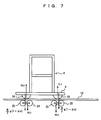
- FIG. 7 shows a model of wheel pressures applied to front and rear drive wheels 34 of the stacker crane 2.
- the mass, and acceleration of the stacker crane 2 are "m” and "a”, respectively, due to the inertial force applied to the center of the gravity of the stacker crane 2, the gravity “mg” is not equally distributed to the front and rear drive wheels. Therefore, the gravity supported by the front drive wheel can be expressed by "mg(1- ⁇ a)/2 ( ⁇ is a proportionality coefficient)", and the gravity supported by the rear drive wheel can be expressed by "mg (1+ ⁇ a)/2". It is assumed that wheel pressure applied to the rollers of the front and rear two wheels of the carriage 4 is N3.
- the type of the carriage can be determined arbitrarily.
- the drive wheels may contact the traveling rail upwardly.
- the adherence rollers may contact the traveling rail downwardly.
Landscapes
- Engineering & Computer Science (AREA)
- Structural Engineering (AREA)
- Mechanical Engineering (AREA)
- Transportation (AREA)
- Civil Engineering (AREA)
- Life Sciences & Earth Sciences (AREA)
- Geology (AREA)
- Warehouses Or Storage Devices (AREA)
- Forklifts And Lifting Vehicles (AREA)
Abstract
Description
- The present invention relates to a carriage of a stacker crane or other rail guided vehicles, or a carriage of an overhead traveling vehicle. In particular, the present invention relates to a carriage having drive wheels on front and rear sides of a vehicle body.
- Patent Publication 1 (
Japanese Patent Publication No. 2002-362709 - An object of the present invention is to make it possible to perform high acceleration driving without increasing the overall height or the overall width of a carriage, and eliminate the necessity of reduction gears between travel motors and drive wheels.
Another object of the present invention is to provide a transmission mechanism between travel motors and drive wheels in a compact space.
Still another object of the present invention is to transmit the force from travel motors equally to left and right sides of drive wheels. - In the present invention, a carriage has front and rear drive wheels. A plurality of travel motors are provided above each of front and rear drive wheels. The plurality of travel motors and the drive wheels are connected by pulleys connected to respective drive shafts of the travel motors, belts, and pulleys connected to respective drive shafts of the drive wheels, without any reduction gears.
- The number of the travel motors for each of the drive wheels may be four, for example. Preferably, two motors are provided for each of the drive wheels. Preferably, drive shafts of the travel motors are laid horizontally. It is particularly preferable that the drive shafts are oriented to the left side and the right side in a traveling direction, i.e., the drive shafts are oriented in a direction perpendicular to the traveling direction in a horizontal plane. Further, preferably, the drive shafts of the travel motors are oriented in opposite directions to each other.
Further, preferably, the travel motors are equally distanced from the drive wheel. - In the present invention, a method for driving a carriage having a front drive wheel and a rear drive wheel comprises the steps of:
- providing a plurality of travel motors above each of the drive wheels;
- connecting the plurality of travel motors and the drive wheels by pulleys connected to respective drive shafts of the travel motors, belts, and pulleys connected to respective drive shafts of the drive wheels, without any reduction gears; and
- driving the drive wheels by the travel motors.
- In the carriage of the present invention, each of the front and rear drive wheels of the carriage are driven by the plurality of the travel motors. Therefore, high acceleration driving can be performed using short travel motors. Further, since the travel motors are positioned above each of the drive wheels, the overall length or the overall width of the carriage does not increase. Further, since the travel motors are provided in parallel with drive shaft of the drive wheel, power transmission can be performed easily. Further, by connecting the pulleys connected to the drive shafts of the travel motors and the pulleys connected to the drive shafts of the drive wheels using belts, deceleration can be carried out based on the ratio between the diameters of the pulleys. Therefore, no reduction gear is required.
- Further, in the case where a plurality of travel motors are arranged such that the drive shafts of the carriages are oriented to the left and right in the traveling direction, in opposite directions to each other, since the pulleys and belts can be provided on the left and right sides in the traveling direction of the carriage, it is possible to drive the drive wheels in a compact space easily.
- In the case where a plurality of travel motors are equally distanced from the drive wheel, it is possible to transmit the force equally to left and right sides of the drive wheels.
-
- [FIG. 1]
FIG. 1 is a side view showing a stacker crane according to an embodiment. - [FIG. 2]
FIG. 2 is a partial cross sectional view in a vertical direction showing components and belt driving of a drive wheel using travel motors in the stacker crane according to the embodiment. - [FIG. 3]
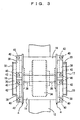
FIG. 3 is a plan view showing main components and positions of the travel motors for driving the drive wheel in the stacker crane according to the embodiment. - [FIG. 4]
FIG. 4 is a front view showing main components of a mechanism of applying wheel pressures to adherence rollers in the stacker crane according to the embodiment. - [FIG. 5]
FIG. 5 is a side view showing main components of the mechanism of applying wheel pressures to a pair of front and rear adherence rollers in the stacker crane according to the embodiment. - [FIG. 6]
FIG. 6 is a block diagram showing control of four travel motors in the stacker crane according to the embodiment. - [FIG. 7]
FIG. 7 is a view illustrating wheel pressures applied to front and rear drive wheels in the stacker crane according to the embodiment. -
- 2: stacker crane
- 4: carriage
- 6: mast
- 8: elevation frame
- 10: transfer apparatus
- 12: traveling rail
- 13: first leg
- 14: second leg
- 16, 17: pulley
- 18, 19: travel motor
- 20: belt
- 22: side roller
- 24, 25: adherence roller
- 26: rocking base
- 27, 29: pin
- 29: connecting member
- 30: spring
- 31: bolt
- 32, 33: pulley
- 34: drive wheel
- 36: drive shaft
- 38: motor support
- 40, 44: bolt
- 42,45: fixed member
- 46: plate
- 47: nut
- 50: encoder
- 51: position and velocity calculator
- 52: velocity pattern generator
- 54: error calculator
- 55: torque controller
- FIGS. 1 to 7 show an embodiment of a
stacker crane 2 as an example. In the drawings, areference numeral 4 denotes a carriage. An additional carriage may be provided in an upper part of thestacker crane 2. Areference numeral 6 denotes a mast. Though the mast has a gate shape in the illustrated embodiment, the shape of themast 6 can be determined arbitrarily. Areference numeral 8 denotes an elevation frame. For example, atransfer apparatus 10 such as a slide fork is mounted on theelevation frame 8 along themast 6. By theelevation frame 8, the height of the center of the gravity of thestacker crane 2 changes. Areference numeral 12 denotes a traveling rail, areference numeral 13 denotes a first leg, and areference numeral 14 denotes a second leg. By keeping thefirst leg 13 at a certain height, and allowing thesecond leg 14 to take a plurality of heights, it is possible to change the height of the travelingrail 12 relative to the ground level. -
Reference numerals pulleys 16 are provided respectively at front and rear positions of on one of the left and right sides of thecarriage 4, and thepulleys 17 are provided respectively at front and rear positions on the other of the left and right sides of thecarriage 4.Reference numerals travel motors carriage 4. Thepulleys belts 20.Reference numerals 22 denote side rollers provided at four positions, i.e., front left, front right, rear left, and rear right positions for limiting the position of thecarriage 4 in the left-right direction with respect to the travelingrail 12. In the specification, the front and rear sides of thestacker crane 2 are defined along the traveling direction. The left-right direction is a direction perpendicular to the traveling direction in a horizontal plane, in which articles are transferred by atransfer apparatus 10. -
Reference numerals adherence rollers rail 12 to increase the wheel pressure applied to the drive wheel 34 (FIGS. 2 to 4). Therollers bases 26 such that therollers rail 12 at substantially the same wheel pressure. Each of the rocking bases 26 is connected to a connectingmember 28 using apin 27 such that rocking movement of the rocking bases 26 is permitted. An end of the connectingmember 28 is rotatably connected to thecarriage 4 using apin 29, and the other end of the connectingmember 28 is connected to thecarriage 4 through abolt 31 and aspring 30 such that the rockingbase 26 is biased upwardly. - As shown in FIGS. 2 and 3, the
pulley 32 is provided at the drive shaft of thetravel motor 18, and thepulley 33 is provided at the drive shaft of thetravel motor 19. Thepulley 32 and thepulley 33 are connected to thepulleys belts 20. Thepulley 32 and thepulley 16 are provided at the front and rear positions of one of the left and right sides of thecarriage 4, and thepulley 33 and thepulley 17 are provided at the front and rear positions of the other of the left and right sides of thecarriage 4. The diameter of thepulley 32 and the diameter of thepulley 33 have the same size, and the diameter of thepulley 16 and the diameter of thepulley 17 have the same size. Based on the ratio between these diameters, the output of themotors reference numeral 34 denotes the drive wheel, and areference numeral 36 denotes a drive shaft of thedrive wheel 34. Thetravel motors drive wheel 34 such that the drive shaft of thetravel motor 18 and the drive shaft of thetravel motor 19 are oriented oppositely in the left-right directions in a horizontal plane. In the structure, thedrive wheel 34 is driven by a large torque, and the overall length of thecarriage 4 is reduced. For example, the number of travel motors for each drive wheel may be four. Thetravel motors members 42 fixed to thecarriage 4 usingbolts 40. By adjusting the height of thebolts 40, it is possible to adjust the tension force applied to thebelts 20. - In the embodiment, the
drive wheels 34 are provided on front and rear sides of thecarriage 4. Thedrive wheels 34 are driven by thetravel motors belts 20. Using the ratios between the diameters of thepulleys pulleys carriage 4, travel units having the same structure including thetravel motors drive wheel 34, or the like are used. - As shown in e.g., FIG. 2, the
first leg 13 and thesecond leg 14 are connected by abolt 44. As describe above, in the case where thesecond leg 14 can take a plurality of heights, it is possible to change the height of the travelingrail 12 from the ground level. Preferably, the diameters of theadherence rollers stacker crane 2, i.e., the height of themast 6 or the weight of the transported article. As a result, it becomes necessary to change the height position of the travelingrail 12. In the case where thesecond leg 14 can take a plurality of heights, it is easy to change the height position of the travelingrail 12. - As shown in FIGS. 4 and 5, the
bolt 31 attached to an end of the connectingmember 28 passes through the fixedmember 45 fixed to thecarriage 4, and then, passes through aspring 30 between the connectingmember 28 and aplate 46. Thebolt 31 is fixed to theplate 46 using anut 47. Thus, by adjusting the position of thenut 47, it is possible to freely adjust the upward biasing force by thespring 30, and it is possible to adjust the wheel pressure applied to each of the front andrear drive wheels 34. - FIG. 6 shows a control mechanism for the
travel motors rear travel motors 18 to monitor the rotation numbers. Position andvelocity calculators 51 determine the current position and the velocity of the carriage. The error between the object position and the present position calculated by avelocity pattern generator 52 and the error between the object velocity and the present velocity calculated similarly are calculated byerror calculators 54.Torque controllers 55control travel motors travel motors 18 are masters, and thetravel motors 19 are slaves. That is, the travel motors on one of the left and right sides are masters, and the travel motors on the other of the left and right sides are slaves. In the case where the wheel pressure between the adherence rollers and the traveling rail is increased to reduce the influence of acceleration of the stacker crane, the control is implemented by using one of the fourmotors travel motors - FIG. 7 shows a model of wheel pressures applied to front and
rear drive wheels 34 of thestacker crane 2. Assuming that the mass, and acceleration of thestacker crane 2 are "m" and "a", respectively, due to the inertial force applied to the center of the gravity of thestacker crane 2, the gravity "mg" is not equally distributed to the front and rear drive wheels. Therefore, the gravity supported by the front drive wheel can be expressed by "mg(1-αa)/2 (α is a proportionality coefficient)", and the gravity supported by the rear drive wheel can be expressed by "mg (1+αa)/2". It is assumed that wheel pressure applied to the rollers of the front and rear two wheels of thecarriage 4 is N3. Since the gravity applied front and rear positions of thecarriage 4 changes, the wheel pressures N1, N2 applied to thedrive wheels 34 are expressed as follows:

Even during high acceleration driving of thestacker crane 2, it is possible to increase the wheel pressures applied to the front andrear drive wheels 34 by the wheel pressure N3. Thus, the necessity of limiting the output torque of the travel motor for the smaller wheel pressure is reduced. - The following advantages are obtained in the embodiment.
- 1) Since the wheel pressures applied to the
drive wheels 34 are increased, high acceleration driving becomes possible. - 2) By the rocking
bases 26, the pair ofrollers rail 12. - 3) By the
spring 30 and the connectingmember 28, the wheel pressures of therollers rollers drive wheels 34 occurs, it is possible to maintain the wheel pressures to have substantially suitable values. - 4) By driving each of the front and
rear drive wheels 34 using the pair oftravel motors - 5) By providing the pair of
travel motors drive wheel 34, it is possible to reduce the overall length of thestacker crane 2. - 6) By arranging the drive shafts of the pair of the
travel motors stacker crane 2, thetravel motors - 7) Using the ratios between the diameters of the
pulleys pulleys - Although the embodiment has been descried in connection with the case in which the carriage of the
stacker crane 2 is used as an example, the type of the carriage can be determined arbitrarily. In the case of using a carriage of an overhead traveling vehicle, the drive wheels may contact the traveling rail upwardly. In this case, the adherence rollers may contact the traveling rail downwardly.
Claims (4)
- A carriage having at least a front drive wheel and at least a rear drive wheel, the carriage comprising:a plurality of front travel motors positioned above the front drive wheel;a plurality of rear travel motors positioned above the rear drive wheel;a plurality of front drive pulleys connected to respective drive shafts of the front travel motors without any reduction gear in a one to one relationship;a plurality of rear drive pulleys connected to respective drive shafts of the rear travel motors without any reduction gear in a one to one relationship;a plurality of front wheel pulleys connected to a drive shaft of the front drive wheel;a plurality of rear wheel pulleys connected to a drive shaft of the rear drive wheel;a plurality of belts connecting the front drive pulleys and the front wheel pulleys; anda plurality of belts connecting the rear drive pulleys and the rear wheel pulleys.
- The carriage of claim 1, the drive shafts of said front travel motors being perpendicular to a traveling direction of the carriage in a horizontal plane and being oriented in opposite directions to each other; the drive shafts of said rear travel motors being perpendicular to the traveling direction of the carriage and being oriented in opposite directions to each other.
- The carriage of claim 2, said plurality of front travel motors being equally distanced from the front drive wheel; said plurality of rear travel motors being equally distanced from the rear drive wheel.
- A method for driving a carriage having at least a front drive wheel and at least a rear drive wheel comprising the steps of:providing a plurality of front travel motors above the front drive wheel;providing a plurality of rear travel motors above the rear drive wheel;connecting a plurality of front drive pulleys to respective drive shafts of the front travel motors without any reduction gear;connecting a plurality of rear drive pulleys to respective drive shafts of the rear travel motors without any reduction gear;connecting a plurality of front wheel pulleys to a drive shaft of the front drive wheel;connecting a plurality of rear wheel pulleys to a drive shaft of the rear drive wheel;driving the front wheel pulleys by the front drive pulleys with belts; anddriving the rear wheel pulleys by the rear drive pulleys with belts.
Applications Claiming Priority (1)
| Application Number | Priority Date | Filing Date | Title |
|---|---|---|---|
| JP2006241762A JP4232206B2 (en) | 2006-09-06 | 2006-09-06 | Traveling cart |
Publications (3)
| Publication Number | Publication Date |
|---|---|
| EP1897837A2 true EP1897837A2 (en) | 2008-03-12 |
| EP1897837A3 EP1897837A3 (en) | 2009-05-20 |
| EP1897837B1 EP1897837B1 (en) | 2010-06-30 |
Family
ID=38904705
Family Applications (1)
| Application Number | Title | Priority Date | Filing Date |
|---|---|---|---|
| EP07017223A Not-in-force EP1897837B1 (en) | 2006-09-06 | 2007-09-03 | Carriage having front and rear drive wheels |
Country Status (5)
| Country | Link |
|---|---|
| EP (1) | EP1897837B1 (en) |
| JP (1) | JP4232206B2 (en) |
| KR (1) | KR20080022530A (en) |
| DE (1) | DE602007007408D1 (en) |
| TW (1) | TW200819379A (en) |
Cited By (6)
| Publication number | Priority date | Publication date | Assignee | Title |
|---|---|---|---|---|
| CN107140358A (en) * | 2017-05-11 | 2017-09-08 | 广州傲胜机器人科技有限公司 | A kind of Automatic Warehouse |
| US9802801B2 (en) | 2012-09-05 | 2017-10-31 | Murata Machinery, Ltd. | Stacker crane |
| US9834422B2 (en) | 2012-09-05 | 2017-12-05 | Murata Machinery, Ltd | Stacker crane |
| EP3336047A1 (en) * | 2016-12-15 | 2018-06-20 | Jungheinrich Aktiengesellschaft | Shelf serving device |
| EP3336048A1 (en) * | 2016-12-15 | 2018-06-20 | Jungheinrich Aktiengesellschaft | Shelf serving device |
| CN116040180A (en) * | 2022-12-30 | 2023-05-02 | 深圳市海柔创新科技有限公司 | Mobile chassis, robots and storage systems |
Families Citing this family (1)
| Publication number | Priority date | Publication date | Assignee | Title |
|---|---|---|---|---|
| CN106345125B (en) * | 2016-10-31 | 2022-08-30 | 江西理工大学 | Three-wheel carbon-free trolley with line-driven steering-walking 8-shaped |
Family Cites Families (4)
| Publication number | Priority date | Publication date | Assignee | Title |
|---|---|---|---|---|
| US3059782A (en) * | 1959-09-10 | 1962-10-23 | Drott Mfg Corp | Mobile lift |
| US3837291A (en) * | 1972-06-21 | 1974-09-24 | Dresser Ind | Crane bridge belt drive |
| DE4436520C1 (en) * | 1994-10-13 | 1995-09-07 | Wampfler Gmbh | Rail-mounted trolley arrangement |
| IT1310853B1 (en) * | 1999-10-08 | 2002-02-22 | Fantuzzi Reggiane Spa | UNIVERSAL TRAVEL GROUP FOR CRANE LEGS OR SIMILAR |
-
2006
- 2006-09-06 JP JP2006241762A patent/JP4232206B2/en not_active Expired - Fee Related
-
2007
- 2007-09-03 DE DE602007007408T patent/DE602007007408D1/en active Active
- 2007-09-03 EP EP07017223A patent/EP1897837B1/en not_active Not-in-force
- 2007-09-04 TW TW096132891A patent/TW200819379A/en unknown
- 2007-09-06 KR KR1020070090467A patent/KR20080022530A/en not_active Withdrawn
Cited By (6)
| Publication number | Priority date | Publication date | Assignee | Title |
|---|---|---|---|---|
| US9802801B2 (en) | 2012-09-05 | 2017-10-31 | Murata Machinery, Ltd. | Stacker crane |
| US9834422B2 (en) | 2012-09-05 | 2017-12-05 | Murata Machinery, Ltd | Stacker crane |
| EP3336047A1 (en) * | 2016-12-15 | 2018-06-20 | Jungheinrich Aktiengesellschaft | Shelf serving device |
| EP3336048A1 (en) * | 2016-12-15 | 2018-06-20 | Jungheinrich Aktiengesellschaft | Shelf serving device |
| CN107140358A (en) * | 2017-05-11 | 2017-09-08 | 广州傲胜机器人科技有限公司 | A kind of Automatic Warehouse |
| CN116040180A (en) * | 2022-12-30 | 2023-05-02 | 深圳市海柔创新科技有限公司 | Mobile chassis, robots and storage systems |
Also Published As
| Publication number | Publication date |
|---|---|
| TW200819379A (en) | 2008-05-01 |
| EP1897837B1 (en) | 2010-06-30 |
| JP2008063067A (en) | 2008-03-21 |
| KR20080022530A (en) | 2008-03-11 |
| EP1897837A3 (en) | 2009-05-20 |
| JP4232206B2 (en) | 2009-03-04 |
| DE602007007408D1 (en) | 2010-08-12 |
Similar Documents
| Publication | Publication Date | Title |
|---|---|---|
| EP1897837B1 (en) | Carriage having front and rear drive wheels | |
| EP1897838A2 (en) | Carriage with increased wheel pressures | |
| US8843233B2 (en) | Intelligent drive control system | |
| KR101446380B1 (en) | Cable railway system | |
| CN1541916B (en) | Conveyance apparatus for use with moving body | |
| KR0147083B1 (en) | Accelerated Moving Walkway | |
| CA2561707A1 (en) | Differential drive spiral accumulator apparatus | |
| CN101314451B (en) | Pedal steering apparatus, steering method of conveyor and conveyor with low structure height | |
| US9359143B2 (en) | Conveyance device | |
| CN106740723A (en) | Heavy-load robot | |
| CN102897640A (en) | Drive system for driving moving walkways | |
| US20130220767A1 (en) | Acceleration and deceleration device and acceleration and deceleration escalator including the same | |
| JP2000226170A (en) | Moving device disposed for guiding carrying means along at least two rails | |
| CN209428029U (en) | Automatic guided vehicle and lifting mechanism | |
| CN207712813U (en) | Anti-slip sprocket drive system | |
| CN216104570U (en) | Floating type automatic turning-around equipment | |
| CN211544842U (en) | Belt guide balancer for belt conveyors | |
| CN210551201U (en) | Guide rail-free truss robot | |
| CN115157942B (en) | A differentially driven land-rail dual-purpose chassis | |
| CN112811117A (en) | Four-way walking backpack type roller vehicle | |
| CN206053448U (en) | A kind of comb floor truck of multi-storied garage with car correction is carried | |
| US5111898A (en) | Variable configuration intervention vehicle for rough ground | |
| CN223990475U (en) | Section bar conveying device with guide | |
| CN218778701U (en) | Multi-stage jacking device | |
| JP3382679B2 (en) | Acceleration / deceleration type moving sidewalk |
Legal Events
| Date | Code | Title | Description |
|---|---|---|---|
| PUAI | Public reference made under article 153(3) epc to a published international application that has entered the european phase |
Free format text: ORIGINAL CODE: 0009012 |
|
| AK | Designated contracting states |
Kind code of ref document: A2 Designated state(s): AT BE BG CH CY CZ DE DK EE ES FI FR GB GR HU IE IS IT LI LT LU LV MC MT NL PL PT RO SE SI SK TR |
|
| AX | Request for extension of the european patent |
Extension state: AL BA HR MK YU |
|
| PUAL | Search report despatched |
Free format text: ORIGINAL CODE: 0009013 |
|
| AK | Designated contracting states |
Kind code of ref document: A3 Designated state(s): AT BE BG CH CY CZ DE DK EE ES FI FR GB GR HU IE IS IT LI LT LU LV MC MT NL PL PT RO SE SI SK TR |
|
| AX | Request for extension of the european patent |
Extension state: AL BA HR MK RS |
|
| 17P | Request for examination filed |
Effective date: 20090901 |
|
| GRAP | Despatch of communication of intention to grant a patent |
Free format text: ORIGINAL CODE: EPIDOSNIGR1 |
|
| AKX | Designation fees paid |
Designated state(s): CH DE LI SE |
|
| GRAS | Grant fee paid |
Free format text: ORIGINAL CODE: EPIDOSNIGR3 |
|
| GRAA | (expected) grant |
Free format text: ORIGINAL CODE: 0009210 |
|
| AK | Designated contracting states |
Kind code of ref document: B1 Designated state(s): CH DE LI SE |
|
| REG | Reference to a national code |
Ref country code: CH Ref legal event code: EP |
|
| REG | Reference to a national code |
Ref country code: CH Ref legal event code: NV Representative=s name: BOVARD AG PATENTANWAELTE |
|
| REF | Corresponds to: |
Ref document number: 602007007408 Country of ref document: DE Date of ref document: 20100812 Kind code of ref document: P |
|
| REG | Reference to a national code |
Ref country code: SE Ref legal event code: TRGR |
|
| PGFP | Annual fee paid to national office [announced via postgrant information from national office to epo] |
Ref country code: SE Payment date: 20100914 Year of fee payment: 4 |
|
| REG | Reference to a national code |
Ref country code: CH Ref legal event code: PFA Owner name: MURATA MACHINERY, LTD. Free format text: MURATA MACHINERY, LTD.#3 MINAMI OCHIAI-CHO, KISSHOIN, MINAMI-KU#KYOTO-SHI, KYOTO 6018326 (JP) -TRANSFER TO- MURATA MACHINERY, LTD.#3 MINAMI OCHIAI-CHO, KISSHOIN, MINAMI-KU#KYOTO-SHI, KYOTO 6018326 (JP) |
|
| PLBE | No opposition filed within time limit |
Free format text: ORIGINAL CODE: 0009261 |
|
| STAA | Information on the status of an ep patent application or granted ep patent |
Free format text: STATUS: NO OPPOSITION FILED WITHIN TIME LIMIT |
|
| 26N | No opposition filed |
Effective date: 20110331 |
|
| REG | Reference to a national code |
Ref country code: DE Ref legal event code: R097 Ref document number: 602007007408 Country of ref document: DE Effective date: 20110330 |
|
| PGFP | Annual fee paid to national office [announced via postgrant information from national office to epo] |
Ref country code: CH Payment date: 20110923 Year of fee payment: 5 |
|
| REG | Reference to a national code |
Ref country code: SE Ref legal event code: EUG |
|
| PG25 | Lapsed in a contracting state [announced via postgrant information from national office to epo] |
Ref country code: SE Free format text: LAPSE BECAUSE OF NON-PAYMENT OF DUE FEES Effective date: 20110904 |
|
| PGFP | Annual fee paid to national office [announced via postgrant information from national office to epo] |
Ref country code: DE Payment date: 20130919 Year of fee payment: 7 |
|
| REG | Reference to a national code |
Ref country code: CH Ref legal event code: PL |
|
| PG25 | Lapsed in a contracting state [announced via postgrant information from national office to epo] |
Ref country code: CH Free format text: LAPSE BECAUSE OF NON-PAYMENT OF DUE FEES Effective date: 20130930 Ref country code: LI Free format text: LAPSE BECAUSE OF NON-PAYMENT OF DUE FEES Effective date: 20130930 |
|
| REG | Reference to a national code |
Ref country code: DE Ref legal event code: R119 Ref document number: 602007007408 Country of ref document: DE |
|
| REG | Reference to a national code |
Ref country code: DE Ref legal event code: R119 Ref document number: 602007007408 Country of ref document: DE Effective date: 20150401 |
|
| PG25 | Lapsed in a contracting state [announced via postgrant information from national office to epo] |
Ref country code: DE Free format text: LAPSE BECAUSE OF NON-PAYMENT OF DUE FEES Effective date: 20150401 |