EP1897803A1 - Holding element for fastening an equipment element to a supporting rail - Google Patents
Holding element for fastening an equipment element to a supporting rail Download PDFInfo
- Publication number
- EP1897803A1 EP1897803A1 EP07115623A EP07115623A EP1897803A1 EP 1897803 A1 EP1897803 A1 EP 1897803A1 EP 07115623 A EP07115623 A EP 07115623A EP 07115623 A EP07115623 A EP 07115623A EP 1897803 A1 EP1897803 A1 EP 1897803A1
- Authority
- EP
- European Patent Office
- Prior art keywords
- holding element
- supporting
- clamping arms
- rail
- plug
- Prior art date
- Legal status (The legal status is an assumption and is not a legal conclusion. Google has not performed a legal analysis and makes no representation as to the accuracy of the status listed.)
- Granted
Links
Images


Classifications
-
- F—MECHANICAL ENGINEERING; LIGHTING; HEATING; WEAPONS; BLASTING
- F16—ENGINEERING ELEMENTS AND UNITS; GENERAL MEASURES FOR PRODUCING AND MAINTAINING EFFECTIVE FUNCTIONING OF MACHINES OR INSTALLATIONS; THERMAL INSULATION IN GENERAL
- F16B—DEVICES FOR FASTENING OR SECURING CONSTRUCTIONAL ELEMENTS OR MACHINE PARTS TOGETHER, e.g. NAILS, BOLTS, CIRCLIPS, CLAMPS, CLIPS OR WEDGES; JOINTS OR JOINTING
- F16B2/00—Friction-grip releasable fastenings
- F16B2/02—Clamps, i.e. with gripping action effected by positive means other than the inherent resistance to deformation of the material of the fastening
- F16B2/06—Clamps, i.e. with gripping action effected by positive means other than the inherent resistance to deformation of the material of the fastening external, i.e. with contracting action
- F16B2/10—Clamps, i.e. with gripping action effected by positive means other than the inherent resistance to deformation of the material of the fastening external, i.e. with contracting action using pivoting jaws
-
- F—MECHANICAL ENGINEERING; LIGHTING; HEATING; WEAPONS; BLASTING
- F16—ENGINEERING ELEMENTS AND UNITS; GENERAL MEASURES FOR PRODUCING AND MAINTAINING EFFECTIVE FUNCTIONING OF MACHINES OR INSTALLATIONS; THERMAL INSULATION IN GENERAL
- F16L—PIPES; JOINTS OR FITTINGS FOR PIPES; SUPPORTS FOR PIPES, CABLES OR PROTECTIVE TUBING; MEANS FOR THERMAL INSULATION IN GENERAL
- F16L3/00—Supports for pipes, cables or protective tubing, e.g. hangers, holders, clamps, cleats, clips, brackets
- F16L3/08—Supports for pipes, cables or protective tubing, e.g. hangers, holders, clamps, cleats, clips, brackets substantially surrounding the pipe, cable or protective tubing
- F16L3/10—Supports for pipes, cables or protective tubing, e.g. hangers, holders, clamps, cleats, clips, brackets substantially surrounding the pipe, cable or protective tubing divided, i.e. with two members engaging the pipe, cable or protective tubing
Definitions
- the invention relates to a holding element for fastening an equipment element to a supporting rail with a rail head having an approximately elliptical cross-sectional outer contour which is fastened to an inner supporting structure of a fuselage cell of an aircraft.
- Holding elements of this type serve, for example, to fasten internal cladding panels, technical installation systems, sanitary and kitchen components or the like.
- individual equipment requirements for the passenger cabins of aircraft make increasingly high demands of the variability of use of such holding elements. Making this more difficult is the fact that the holding elements are to be suitable and capable of use for a multiplicity of different types of aircraft without structural changes.
- the installation of the holding elements is to be made as simple and time-saving as possible.
- such a wide spectrum of demands can only partially be covered, if at all, by the holding elements known from the prior art.
- DE 10 2004 018 736 A1 describes a connecting element for fastening cladding parts to a structure of an aircraft with a holder on the component side, on which a plug-in tenon is held in a manner such that it can be adjusted to a limited extent at least perpendicularly with respect to the surface of the component, and with a receptacle on the structure side with a recess for the plug-in tenon, said recess being adapted to the contour of the plug-in tenon with a form fit in such a manner that said plug-in tenon enters into a snap connection with the receptacle, the receptacle on the structure side having a supporting flange, with which said receptacle bears against a holder on the structure side and is mounted and can be fixed such that it can be adjusted on an X-Y plane perpendicularly with respect to the connecting direction.
- WO 2006/072131 A1 concerns a release means for a locking system, which is particularly suitable for fastening a first element, for example a panel, to a support adjacent to a second element, for example a further panel.
- This holding element comprises, inter alia:
- the supporting rail constitutes a connecting system which can be used extremely flexibly and can be very easily adapted to different lengths of fuselage cells of aircraft. Furthermore, the supporting rail enables the holding element to be fastened in any desired positions over its entire length.
- the installation of the holding element proves to be simple in this case, since the clamping arms are first of all snapped onto the rail head at the desired fitting location and the holding element is therefore secured against dropping down. In this state, the holding element can be displaced as desired along the supporting rail in order to undertake a precision alignment or to reach a definitive installation position. If the holding element is then pressed from below against the supporting rail, the holding element is definitively locked and can no longer be displaced.
- Fig. 1 shows a perspective view of a holding element 1 which is latched together with and locked to a supporting rail 2.
- the supporting rail 2 is fastened to an inner supporting structure, not illustrated, of a passenger cabin of a fuselage cell of an aircraft.
- the supporting rail 2 has a rail head 3 which has approximately an elliptical cross-sectional outer contour and is preferably of hollow design on the inside.
- the holding element 1 comprises, inter alia, two curved clamping arms 4, 5, a locking frame 6, a bearing frame 7 and a supporting arm 8.
- the supporting arm 8 has a base plate 9 and two supports 10, 11, which are arranged thereon, for the fastening of an equipment element, not illustrated, for example an inner cladding panel or the like.
- the clamping arms 4, 5 are curved in such a manner that, in the latched-on state of the holding element 1, they bear against the rail head 3 as far as possible with a form fit over the entire surface in order to ensure a sufficiently firm fit.
- the curvature of the clamping arms 4, 5 corresponds essentially to the elliptical cross-sectional outer contour of the rail head 3.
- Cross-sectional geometries which deviate from the elliptical cross-sectional outer contour of the rail head 3 are possible.
- the cross-sectional geometry of the rail head 3 may also be of circular design.
- the clamping arms 4, 5 are coupled resiliently to the bearing frame 7 and are pressed fixedly against the rail head 3 by spring force.
- the holding element 1 has an actuating lever 12 which can be pivoted by a user and with which the locking of the holding element 1 on the supporting rail 2 can be released again if the need arises.
- Fig. 2 shows a side view of the holding element 1 in the fully locked state.
- the clamping arms 4, 5 are coupled pivotably to the bearing frame 7 and are pressed fixedly against the rail head 3 of the supporting rail 2 by two spring elements which, in the exemplary embodiment shown in Fig. 2, are designed in the form of leaf springs 13, 14.
- the clamping arms 4, 5 therefore bear virtually over their entire surface against the rail head 3, i.e. a form fit is provided at least in some regions between the clamping arms 4, 5 and the rail head 3.
- the locking frame 6, the longitudinal edges 15, 16 of which bear fixed against the clamping arm outer surfaces 17, 18 prevents pivoting of the clamping arms 4, 5 and therefore inadvertent pulling off of the holding element 1 from the rail head 3 of the supporting rail 2.
- the equipment element is fastened to the supporting arm 8 by means of the supports 10, 11.
- the supports 10, 11 can each have at least one hole.
- the holding element 1 can be unlocked if the need arises by means of the actuating lever 12.
- Fig. 3 illustrates the detailed construction of the holding element in a perspective, exploded illustration.
- the supporting arm 8 has two supports 10, 11 which are directed downwards sideways and have fastening holes for the connection of an equipment element.
- the bearing frame 7 is fastened to the supporting arm 8 by two elastic buffer elements which, in the exemplary embodiment shown, are designed as hollow-cylindrical silicone buffers 19, 20.
- the silicone buffers 19, 20 can be connected to the bearing frame 7 and the supporting arm 8 by a rivet connection or clamping connection, for example. In a departure from this, a different number of buffer elements can also be provided.
- the buffer elements can also be designed as rubber buffers. The mechanical prestressing between the locking frame 6, the bearing frame 7 and the support 8, which prestressing is produced by the buffer elements, at the same time prevents rattling noises from arising.
- a spring clip 22 is arranged on a rectangular base plate 21 of the bearing frame 2.
- the spring clip 22 can be, for example, riveted to the base plate 21.
- four bearing brackets 23 to 26 are arranged on the base plate 21.
- the clamping arm 4 is coupled pivotably to the bearing brackets 23, 24, and the clamping arm 5 is coupled pivotably to the bearing brackets 25, 26.
- the articulated connection takes place between the clamping arms 4, 5 and the bearing frame 7 by means of shaft sections, not denoted specifically, in the lower region of the clamping arms 4, 5, which shaft sections can be latched into corresponding receptacles, likewise not denoted with a reference number, on the bearing brackets 23 to 26.
- two pins are arranged on the supporting arm 8 and are used to connect the supporting arm 8 to the locking frame 6. In the assembled state of the holding element 1, the bearing frame 7 is located between the base plate 21 of the supporting arm 8 and the locking frame 6.
- a total of four torsion springs 29 to 32 are provided in the embodiment of the holding element 1 according to Fig. 3.
- the clamping arm 4 is pressed against the rail head 3 of the supporting rail 2 by means of the torsion springs 29, 30 while the torsion springs 31, 32 ensure a sufficient degree of contact pressure of the clamping arm 5.
- Each of the torsion springs 29 to 32 has two limbs, which are not provided with a reference number for reasons of better graphical clarity.
- One limb in each case of the torsion springs 29 to 32 is accommodated in in each case one of four holes in the two clamping arms 4, 5 while the other limb in each case is accommodated in in each case one of four holes in the locking frame 6.
- the limbs of the torsion springs 29 to 32 and the total of eight holes in the clamping arms 4, 5 and in the locking frame 6 have not been provided with a reference number for better graphical clarity.
- the openings of the torsion springs 29 to 32 are plugged onto short tenons, which are fastened laterally to the clamping arms 4, 5 and do not have a reference number, and are therefore additionally secured against dropping off.
- a plug-in pin 33 is fastened pivotably in a hole 34 in the base plate 9 of the supporting arm 8. In order to ensure simple pivotability by means of a user, the plug-in pin 33 is connected in a rotationally fixed manner to the bent actuating lever 12. The plug-in pin 33 can be latched into the spring clip 22 for fastening purposes and can be unlatched again from the spring clip 22 by pivoting of the actuating lever 12.
- the plug-in pin 33 has two grooves or wedge-shaped recesses which are placed into the plug-in pin 33, in each case on opposite sides in the end region thereof, transversely with respect to a longitudinal axis of the plug-in pin 33.
- the grooves 35, 36 can be latched on one of the two spring arms 37, 38 by a respective latching edge in order to lock the plug-in pin 33 in the spring clip 22.
- the spring clip 22 can be slightly spread open by rotation of the plug-in pin 33, and therefore the plug-in pin 33 can be pulled out of said spring clip again.
- only the grooves 35, 36 and the two spring arms 37, 38 of the spring clip 22 have been provided with a reference number in the illustration of Fig. 3.
- the spring clip 22 in conjunction with the plug-in pin 33 permits a connection, which can be released again at any time if the need arises, between the supporting arm 8 and the bearing frame 7, the bearing frame 7, for its part, being connected to the clamping arms 4, 5 in an articulated and resilient manner.
- the holding element 1 is joined mechanically to the supporting rail 2 by means of the clamping arms 4, 5.
- the locking frame 6 serving essentially to secure the clamping arms 4, 5 against inadvertent expansion in the locked state of the holding element 1 is connected via the pins to the supporting arm 8, i.e. is plugged onto the latter.
- the bearing frame 7 has the task of forming an abutment for the leaf springs (cf. Fig. 2) and the four torsion springs 29 to 32.
- the locking of the clamping arms 4, 5 takes place via the longitudinal edges 15, 16 of the locking frame 6, which, in the locked state, bear against the clamping arm outer surfaces 17, 18.
- the locking frame 6 which is open on the inside (lattice frame structure) is designed as a single piece and is preferably formed by a fibre-reinforced plastics material.
- the locking frame 6 does not have a base plate and is formed by two longitudinal members which run in parallel and are connected at their ends to a cross member running in an approximately U-shaped manner in each case.
- the inwardly pointing longitudinal edges 15, 16 of the longitudinal members of the locking frame form the stop surfaces for the clamping arms 4, 5 while the transverse members of the locking frame 6 rest on the base plate 9 of the supporting arm 8.
- the longitudinal and the transverse members forming the locking frame 6 do not have any reference numbers.
- the plug-in pin 33 is latched into the spring clip 22 counter to the spring force of the silicone buffers 19, 20 or the rubber buffers.
- the mechanical force F to be applied for latching the plug-in pin 33 to the spring clip 22 (cf. Fig. 3, white direction arrow) can be adjusted as desired by variation of the height of the silicone buffers 19, 20 and/or of the elasticity of the silicone buffers 19, 20.
- the vertical displacement of the base plate 9 of the supporting arm 8 with respect to the horizontal, which displacement is caused by the silicone buffers 19, 20 being pressed in, serves at the same time as a type of "optical latching indication" in order to indicate the latched state of the holding element 1 unequivocally to a user at a glance.
- the clamping arms 4, 5 are at the same time secured against inadvertent pivoting and a resultantly caused detachment from the supporting arm 2 by means of the longitudinal edges 15, 16 which bear against the clamping arm outer surfaces 17, 18.
- the fixed bearing of the longitudinal edges 15, 16 against the clamping arm outer surfaces 17, 18 is achieved by the vertical displacement of the supporting arm 8, which is caused as a consequence of the latching-in operation, and the locking frame 6, which is arranged on said supporting arm, in conjunction with the mechanical prestressing produced as a result.
- the holding element 1 is in a "locked state” (locking state), i.e. in a completely secured state, and can no longer be pulled off from the supporting rail 2 or displaced on the latter parallel to a longitudinal axis 39.
- the holding element 1 is in a "clamped-on state” (installation state) in which, although the holding element 1 is held securely on the supporting rail 2 by the clamping arms 4, 5 and is merely secured against unchecked dropping down, displaceability or alignment on the supporting rail 2 in the direction of the longitudinal axis 39 is (still) possible.
- the holding element 1 according to the invention is to be definitively locked, clamped or fixed on the supporting rail 2 or the rail head 3, then, according to Fig. 6, the holding element 1 or the supporting arm 8 is pressed with a defined force further in the direction of the rail 43 until the plug-in pin 33 completely latches into the spring clip 22 and the holding element 1 is definitively fixed on the supporting rail 2.
- the clamping arms 4, 5 are secured against inadvertent expansion and a resultantly caused release of the holding element 1 from the supporting rail 2 by the longitudinal edges 15, 16 of the locking frame 6.
- the clamping arms 4, 5 preferably bear with a full form-fitting connection against the rail head 3 in order to ensure an as efficient transmission of force as possible between the holding element 1 and the supporting rail 2.
- the holding element 1 If the holding element 1 is to be released again from the supporting rail 2 (cf. Fig. 4), a user first of all has to expand (unlock) the spring clip 22, by a slight pivoting of the plug-in pin 33, to an extent such that the plug-in pin 33 disengages from the spring clip 22 and can be pulled out downward from the latter. The holding element 1 can subsequently be pulled downward a short distance. During this pulling-off operation, the clamping arms 4, 5 are at the same time released again from the longitudinal edges 15, 16 of the locking frame 6, since, during this operation, the locking frame 6 is also moved downwards by a corresponding amount. However, the holding element 1 does not drop off from the supporting rail 2 in an unchecked manner.
- the holding element 1 is then completely pulled off from the rail head 3 of the supporting rail 2 by further expansion of the clamping arms 4, 5.
- the holding element 1 permits a simple, rapid and flexible fastening of a multiplicity of very different equipment elements.
- the holding element 1 has great variability of use, and can therefore be used in a multiplicity of different types of aircraft without modifications.
Landscapes
- Engineering & Computer Science (AREA)
- General Engineering & Computer Science (AREA)
- Mechanical Engineering (AREA)
- Clamps And Clips (AREA)
- Flanged Joints, Insulating Joints, And Other Joints (AREA)
Abstract
Description
- The invention relates to a holding element for fastening an equipment element to a supporting rail with a rail head having an approximately elliptical cross-sectional outer contour which is fastened to an inner supporting structure of a fuselage cell of an aircraft.
- A great variety of holding elements for fastening equipment elements to the inner supporting structure of fuselage cells of aircraft are known from the prior art. Holding elements of this type serve, for example, to fasten internal cladding panels, technical installation systems, sanitary and kitchen components or the like. However, individual equipment requirements for the passenger cabins of aircraft make increasingly high demands of the variability of use of such holding elements. Making this more difficult is the fact that the holding elements are to be suitable and capable of use for a multiplicity of different types of aircraft without structural changes. Furthermore, the installation of the holding elements is to be made as simple and time-saving as possible. However, such a wide spectrum of demands can only partially be covered, if at all, by the holding elements known from the prior art.
-
DE 10 2004 018 736 A1 describes a connecting element for fastening cladding parts to a structure of an aircraft with a holder on the component side, on which a plug-in tenon is held in a manner such that it can be adjusted to a limited extent at least perpendicularly with respect to the surface of the component, and with a receptacle on the structure side with a recess for the plug-in tenon, said recess being adapted to the contour of the plug-in tenon with a form fit in such a manner that said plug-in tenon enters into a snap connection with the receptacle, the receptacle on the structure side having a supporting flange, with which said receptacle bears against a holder on the structure side and is mounted and can be fixed such that it can be adjusted on an X-Y plane perpendicularly with respect to the connecting direction. -
WO 2006/072131 A1 concerns a release means for a locking system, which is particularly suitable for fastening a first element, for example a panel, to a support adjacent to a second element, for example a further panel. - It is therefore an object of the invention to provide a holding element which has great variability of use and which, in addition, can be fitted easily and rapidly in a simple manner.
- The object according to the invention is achieved by a holding element with the features of claim 1.
- This holding element comprises, inter alia:
- a) two curved and pivotable clamping arms which, when clamped on, bear on both sides against the rail head with a form fit at least in some regions and which are displaceable parallel to a longitudinal axis of the supporting rail,
- b) a locking frame with a U-shaped cross-sectional geometry and two longitudinal edges running parallel to and at a distance from each other,
- c) a bearing frame with a rectangular base plate on which four bearing brackets are arranged, one clamping arm in each case being accommodated pivotably in two bearing brackets in each case,
- d) a supporting arm with a base plate with two downwardly pointing supports for the fastening of the equipment element, the supporting arm being connected to the bearing frame by at least two elastic buffer elements,
- e) at least two spring elements which are arranged between the locking frame and the clamping arms in order to press the clamping arms against the rail head with a sufficient degree of force,
- f) at least one spring clip which is fastened in the base plate of the bearing frame, and
- g) a plug-in pin which is fastened pivotably in the base plate of the supporting arm by means of an actuating lever and can be latched to the spring clip, as a result of which the two longitudinal edges of the locking frame are brought into contact with the two clamping arm outer surfaces for final securing in the locked state of the holding element, and a displacement parallel to the longitudinal axis is no longer possible.
- In conjunction with the clamping arms of the holding element, the supporting rail constitutes a connecting system which can be used extremely flexibly and can be very easily adapted to different lengths of fuselage cells of aircraft. Furthermore, the supporting rail enables the holding element to be fastened in any desired positions over its entire length. The installation of the holding element proves to be simple in this case, since the clamping arms are first of all snapped onto the rail head at the desired fitting location and the holding element is therefore secured against dropping down. In this state, the holding element can be displaced as desired along the supporting rail in order to undertake a precision alignment or to reach a definitive installation position. If the holding element is then pressed from below against the supporting rail, the holding element is definitively locked and can no longer be displaced. This provides a visual check on whether it is latched into place. If the holding element is to be released again, all that is required is to pivot an actuating lever in order to unlock it. The holding element does not drop down unchecked in this case, but rather is still held on the supporting rail by the resilient clamping arms. Only after the clamping arms have been pulled off from the supporting rail is the holding element completely detached from the supporting rail and can be used elsewhere or placed on the supporting rail at a different point.
- Further advantageous refinements of the invention are explained in the further patent claims.
- In the drawing:
- Fig. 1
- shows a perspective view of a holding element which has been latched in place on a supporting rail and locked,
- Fig. 2
- shows a side view of the holding element,
- Fig. 3
- shows an exploded illustration of the holding element, and
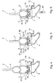
- Figs 4-6
- show a schematized sequence of locking the holding element to the supporting rail.
- Fig. 1 shows a perspective view of a holding element 1 which is latched together with and locked to a supporting
rail 2. - The supporting
rail 2 is fastened to an inner supporting structure, not illustrated, of a passenger cabin of a fuselage cell of an aircraft. The supportingrail 2 has arail head 3 which has approximately an elliptical cross-sectional outer contour and is preferably of hollow design on the inside. The holding element 1 comprises, inter alia, two curvedclamping arms locking frame 6, a bearingframe 7 and a supportingarm 8. The supportingarm 8 has a base plate 9 and two supports 10, 11, which are arranged thereon, for the fastening of an equipment element, not illustrated, for example an inner cladding panel or the like. - The clamping
arms rail head 3 as far as possible with a form fit over the entire surface in order to ensure a sufficiently firm fit. The curvature of the clampingarms rail head 3. Cross-sectional geometries which deviate from the elliptical cross-sectional outer contour of therail head 3 are possible. For example, the cross-sectional geometry of therail head 3 may also be of circular design. The clampingarms frame 7 and are pressed fixedly against therail head 3 by spring force. - Furthermore, the holding element 1 has an
actuating lever 12 which can be pivoted by a user and with which the locking of the holding element 1 on the supportingrail 2 can be released again if the need arises. - Fig. 2 shows a side view of the holding element 1 in the fully locked state.
The clampingarms frame 7 and are pressed fixedly against therail head 3 of the supportingrail 2 by two spring elements which, in the exemplary embodiment shown in Fig. 2, are designed in the form ofleaf springs arms rail head 3, i.e. a form fit is provided at least in some regions between the clampingarms rail head 3. Thelocking frame 6, thelongitudinal edges outer surfaces arms rail head 3 of the supportingrail 2. The equipment element is fastened to the supportingarm 8 by means of thesupports lever 12. - Fig. 3 illustrates the detailed construction of the holding element in a perspective, exploded illustration.
- The supporting
arm 8 has twosupports frame 7 is fastened to the supportingarm 8 by two elastic buffer elements which, in the exemplary embodiment shown, are designed as hollow-cylindrical silicone buffers silicone buffers frame 7 and the supportingarm 8 by a rivet connection or clamping connection, for example. In a departure from this, a different number of buffer elements can also be provided. Furthermore, the buffer elements can also be designed as rubber buffers. The mechanical prestressing between thelocking frame 6, the bearingframe 7 and thesupport 8, which prestressing is produced by the buffer elements, at the same time prevents rattling noises from arising. - Furthermore, a
spring clip 22 is arranged on arectangular base plate 21 of the bearingframe 2. Thespring clip 22 can be, for example, riveted to thebase plate 21. Furthermore, four bearingbrackets 23 to 26 are arranged on thebase plate 21. The clampingarm 4 is coupled pivotably to the bearingbrackets clamping arm 5 is coupled pivotably to the bearingbrackets arms bearing frame 7 by means of shaft sections, not denoted specifically, in the lower region of the clampingarms brackets 23 to 26. Furthermore, two pins are arranged on the supportingarm 8 and are used to connect the supportingarm 8 to thelocking frame 6. In the assembled state of the holding element 1, thebearing frame 7 is located between thebase plate 21 of the supportingarm 8 and thelocking frame 6. - Furthermore, in contrast to the variant embodiment of the holding element 1 according to Fig. 2, a total of four torsion springs 29 to 32 are provided in the embodiment of the holding element 1 according to Fig. 3. The clamping
arm 4 is pressed against therail head 3 of the supportingrail 2 by means of the torsion springs 29, 30 while the torsion springs 31, 32 ensure a sufficient degree of contact pressure of theclamping arm 5. Each of the torsion springs 29 to 32 has two limbs, which are not provided with a reference number for reasons of better graphical clarity. One limb in each case of the torsion springs 29 to 32 is accommodated in in each case one of four holes in the two clampingarms locking frame 6. The limbs of the torsion springs 29 to 32 and the total of eight holes in the clampingarms locking frame 6 have not been provided with a reference number for better graphical clarity. The openings of the torsion springs 29 to 32 are plugged onto short tenons, which are fastened laterally to the clampingarms - A plug-in
pin 33 is fastened pivotably in ahole 34 in the base plate 9 of the supportingarm 8. In order to ensure simple pivotability by means of a user, the plug-inpin 33 is connected in a rotationally fixed manner to thebent actuating lever 12. The plug-inpin 33 can be latched into thespring clip 22 for fastening purposes and can be unlatched again from thespring clip 22 by pivoting of the actuatinglever 12. - For this purpose, the plug-in
pin 33 has two grooves or wedge-shaped recesses which are placed into the plug-inpin 33, in each case on opposite sides in the end region thereof, transversely with respect to a longitudinal axis of the plug-inpin 33. Thegrooves spring arms pin 33 in thespring clip 22. Thespring clip 22 can be slightly spread open by rotation of the plug-inpin 33, and therefore the plug-inpin 33 can be pulled out of said spring clip again. For the sake of better graphical clarity, only thegrooves spring arms spring clip 22 have been provided with a reference number in the illustration of Fig. 3. - The
spring clip 22 in conjunction with the plug-inpin 33 permits a connection, which can be released again at any time if the need arises, between the supportingarm 8 and thebearing frame 7, thebearing frame 7, for its part, being connected to the clampingarms rail 2 by means of the clampingarms - The
locking frame 6 serving essentially to secure the clampingarms arm 8, i.e. is plugged onto the latter. Thebearing frame 7 has the task of forming an abutment for the leaf springs (cf. Fig. 2) and the four torsion springs 29 to 32. The locking of the clampingarms longitudinal edges locking frame 6, which, in the locked state, bear against the clamping armouter surfaces locking frame 6 which is open on the inside (lattice frame structure) is designed as a single piece and is preferably formed by a fibre-reinforced plastics material. Thelocking frame 6 does not have a base plate and is formed by two longitudinal members which run in parallel and are connected at their ends to a cross member running in an approximately U-shaped manner in each case. The inwardly pointinglongitudinal edges arms locking frame 6 rest on the base plate 9 of the supportingarm 8. For the sake of better clarity, the longitudinal and the transverse members forming thelocking frame 6 do not have any reference numbers. - The plug-in
pin 33 is latched into thespring clip 22 counter to the spring force of the silicone buffers 19, 20 or the rubber buffers. The mechanical force F to be applied for latching the plug-inpin 33 to the spring clip 22 (cf. Fig. 3, white direction arrow) can be adjusted as desired by variation of the height of the silicone buffers 19, 20 and/or of the elasticity of the silicone buffers 19, 20. The vertical displacement of the base plate 9 of the supportingarm 8 with respect to the horizontal, which displacement is caused by the silicone buffers 19, 20 being pressed in, serves at the same time as a type of "optical latching indication" in order to indicate the latched state of the holding element 1 unequivocally to a user at a glance. - If the plug-in
pin 33 is latched together with thespring clip 22, the clampingarms arm 2 by means of thelongitudinal edges outer surfaces longitudinal edges outer surfaces arm 8, which is caused as a consequence of the latching-in operation, and thelocking frame 6, which is arranged on said supporting arm, in conjunction with the mechanical prestressing produced as a result. - If the plug-in
bolt 33 is latched together with thespring clip 22, the holding element 1 is in a "locked state" (locking state), i.e. in a completely secured state, and can no longer be pulled off from the supportingrail 2 or displaced on the latter parallel to alongitudinal axis 39.
However, if the plug-inpin 33 is not latched into thespring clip 22, the holding element 1 is in a "clamped-on state" (installation state) in which, although the holding element 1 is held securely on the supportingrail 2 by the clampingarms rail 2 in the direction of thelongitudinal axis 39 is (still) possible. - Figs 4 to 6, to which reference is now made, schematically illustrate the sequence during the fastening of the holding element 1 on the supporting
rail 2. - In the illustration of Fig. 4, the holding element 1 is pushed ever further in the direction of the
arrow 40 onto therail head 3 of the supportingrail 2. In the process, the clampingarms bearing frame 7 in a resilient and articulated manner by means of the torsion springs 29, 30, expand in accordance with the elliptical outer geometry of therail head 3. The plug-inpin 33 is not yet latched together with thespring clip 22 in this state. - In the position illustrated by Fig. 5, the holding element 1 has been pushed upward to an extent such that the
rail head 3 of the supportingrail 2 is completely accommodated between the clampingarms arms arrows rail head 3 with a sufficient degree of mechanical contact pressure force by the action of the torsion springs 29, 32. In this "clamped-on state", a sufficiently secure support of the holding element 1 on the supportingrail 2 or the supportingrail head 3 is already provided by the action of the torsion springs 29, 32. Nevertheless, in this position, any desired displacement of the holding element 1 perpendicular with respect to the plane of projection is still possible. - By this means, correction of the position or compensation of tolerances, or the like, can take place in a simple manner. Latching between the plug-in
pin 33 and thespring clip 22 has also not yet taken place in this position. The longitudinal edges 15, 16 of thelocking frame 6 likewise do not yet bear against the clampingarms arms rail head 3, i.e. the clampingarms rail head 3. - If, however, the holding element 1 according to the invention is to be definitively locked, clamped or fixed on the supporting
rail 2 or therail head 3, then, according to Fig. 6, the holding element 1 or the supportingarm 8 is pressed with a defined force further in the direction of therail 43 until the plug-inpin 33 completely latches into thespring clip 22 and the holding element 1 is definitively fixed on the supportingrail 2. At the same time, the clampingarms rail 2 by thelongitudinal edges locking frame 6. Also in this position, the clampingarms rail head 3 in order to ensure an as efficient transmission of force as possible between the holding element 1 and the supportingrail 2. - If the holding element 1 is to be released again from the supporting rail 2 (cf. Fig. 4), a user first of all has to expand (unlock) the
spring clip 22, by a slight pivoting of the plug-inpin 33, to an extent such that the plug-inpin 33 disengages from thespring clip 22 and can be pulled out downward from the latter. The holding element 1 can subsequently be pulled downward a short distance. During this pulling-off operation, the clampingarms longitudinal edges locking frame 6, since, during this operation, the lockingframe 6 is also moved downwards by a corresponding amount. However, the holding element 1 does not drop off from the supportingrail 2 in an unchecked manner. On the contrary, the clampingarms rail head 3 in a resilient and articulated manner, still ensure a sufficiently fixed mechanical fit in this "clamped-on state" of the holding element 1. For the definitive removal of the holding element 1, the holding element 1 is then completely pulled off from therail head 3 of the supportingrail 2 by further expansion of the clampingarms - The holding element 1 permits a simple, rapid and flexible fastening of a multiplicity of very different equipment elements. The holding element 1 has great variability of use, and can therefore be used in a multiplicity of different types of aircraft without modifications.
-
- 1.
- Holding element
- 2.
- Supporting rail
- 3.
- Rail head
- 4.
- Clamping arm
- 5.
- Clamping arm
- 6.
- Locking frame
- 7.
- Bearing frame
- 8.
- Supporting arm
- 9.
- Base plate
- 10.
- Support
- 11.
- Support
- 12.
- Actuating lever
- 13.
- Leaf spring
- 14.
- Leaf spring
- 15.
- Longitudinal edge (locking frame)
- 16.
- Longitudinal edge (locking frame)
- 17.
- Clamping arm outer surface
- 18.
- Clamping arm outer surface
- 19.
- Silicone buffer
- 20.
- Silicone buffer
- 21.
- Base plate (bearing frame)
- 22.
- Spring clip
- 23.
- Bearing bracket
- 24.
- Bearing bracket
- 25.
- Bearing bracket
- 26.
- Bearing bracket
- 29.
- Torsion spring
- 30.
- Torsion spring
- 31.
- Torsion spring
- 32.
- Torsion spring
- 33.
- Plug-in pin
- 34.
- Hole
- 35.
- Groove
- 36.
- Groove
- 37.
- Spring arm
- 38.
- Spring arm
- 39.
- Longitudinal axis (supporting rail)
- 40.
- Arrow
- 41.
- Arrow
- 42
- Arrow
- 43.
- Arrow
Claims (9)
- Holding element (1) for fastening an equipment element to a supporting rail (2) with a rail head (3) having an elliptical cross-sectional outer contour which is fastened to an inner supporting structure of a fuselage cell of an aircraft, comprising:a) two curved and pivotable clamping arms (4, 5) which, when clamped on, bear on both sides against the rail head (3) with a form fit at least in some regions and which are displaceable parallel to a longitudinal axis (39) of the supporting rail (2),b) a locking frame (6) with a U-shaped cross-sectional geometry and two longitudinal edges (15, 16) running parallel to and at a distance from each other,c) a bearing frame (7) with a rectangular base plate (21) on which four bearing brackets (23 - 26) are arranged, each clamping arm (4, 5) being accommodated pivotably in two respective bearing brackets (23 - 26),d) a supporting arm (8) with a base plate (9) with two downwardly pointing supports (10, 11) for the fastening of the equipment element, the supporting arm (8) being connected to the bearing frame (7) by at least two elastic buffer elements,e) at least two spring elements which are arranged between the locking frame (6) and the clamping arms (4, 5) in order to press the clamping arms (4, 5) against the rail head (3) with a sufficient degree of force,f) at least one spring clip (22) which is fastened in the base plate (21) of the bearing frame (7), andg) a plug-in pin (33) which is fastened pivotably in the base plate (9) of the supporting arm (8) by means of an actuating lever (12) and can be latched to the spring clip (22), as a result of which the two longitudinal edges (15, 16) of the locking frame (6) are brought into contact with the two clamping arm outer surfaces (17, 18) for final securing in the locked state of the holding element (1), and a displacement parallel to the longitudinal axis (39) is no longer possible.
- Holding element (1) according to Claim 1, characterized in that two leaf springs (13, 14) are provided as spring elements.
- Holding element (1) according to Claim 1, characterized in that four torsion springs are provided as spring elements (19, 20).
- Holding element (1) according to one of Claims 1 to 3, characterized in that the spring clip (22) can be expanded by pivoting of the plug-in pin (33) by means of the actuating lever (12), as a result of which the plug-in pin (33) is unlocked.
- Holding element (1) according to one of Claims 1 to 4, characterized in that the plug-in pin (33) has two grooves (35, 36) which are arranged on both sides of the plug-in pin (33) transversely with respect to a longitudinal axis thereof, and the spring clip (22) has two spring arms (37, 38), it being possible for a respective latching edge arranged on one spring arm (37, 38) to latch together with the grooves (35, 36).
- Holding element (1) according to one of Claims 1 to 5, characterized in that the buffer elements are formed, in particular, by elastic silicone buffers (19, 20) or by elastic rubber buffers which have a hollow-cylindrical geometrical form.
- Holding element (1) according to one of Claims 1 to 6, characterized in that at least two pins for connection to the locking frame (6) are arranged on the supporting arm (8).
- Holding element (1) according to one of Claims 1 to 7, characterized in that the clamping arms (4, 5) each have a width of 1 cm up to 5 cm.
- Holding element (1) according to one of Claims 1 to 8, characterized in that the clamping arms (4, 5), the locking frame (6), the bearing frame (7) and the supporting arm (8) are formed from a plastics material.
Applications Claiming Priority (1)
| Application Number | Priority Date | Filing Date | Title |
|---|---|---|---|
| DE102006042337A DE102006042337B3 (en) | 2006-09-08 | 2006-09-08 | Retaining element for fastening an equipment element to a mounting rail |
Publications (2)
| Publication Number | Publication Date |
|---|---|
| EP1897803A1 true EP1897803A1 (en) | 2008-03-12 |
| EP1897803B1 EP1897803B1 (en) | 2010-04-07 |
Family
ID=38728847
Family Applications (1)
| Application Number | Title | Priority Date | Filing Date |
|---|---|---|---|
| EP07115623A Not-in-force EP1897803B1 (en) | 2006-09-08 | 2007-09-04 | Holding element for fastening an equipment element to a supporting rail |
Country Status (4)
| Country | Link |
|---|---|
| US (1) | US7770859B2 (en) |
| EP (1) | EP1897803B1 (en) |
| AT (1) | ATE463418T1 (en) |
| DE (2) | DE102006042337B3 (en) |
Cited By (7)
| Publication number | Priority date | Publication date | Assignee | Title |
|---|---|---|---|---|
| CN102620061A (en) * | 2012-03-31 | 2012-08-01 | 深圳市华星光电技术有限公司 | Line guiding mechanism |
| WO2014173773A1 (en) * | 2013-04-22 | 2014-10-30 | Sanofi-Aventis Deutschland Gmbh | A supplementary device for a manually operable injection device |
| CN107108036A (en) * | 2014-12-05 | 2017-08-29 | B/E航空系统有限公司 | Fastening system for the fastening object in transport facility |
| CN107327710A (en) * | 2017-07-13 | 2017-11-07 | 重庆源隆科技有限公司 | Monitoring pipeline safety system |
| CN107554751A (en) * | 2017-08-22 | 2018-01-09 | 中国商用飞机有限责任公司北京民用飞机技术研究中心 | A kind of stringer protection device |
| CN108331972A (en) * | 2018-02-05 | 2018-07-27 | 魏海勇 | A kind of hydraulic engineering is fixed with water pipe buries equipment |
| CN112758306A (en) * | 2021-04-08 | 2021-05-07 | 中国航天空气动力技术研究院 | Self-tensioning wing rib, wing and skin laying method |
Families Citing this family (28)
| Publication number | Priority date | Publication date | Assignee | Title |
|---|---|---|---|---|
| US8182469B2 (en) * | 1997-11-21 | 2012-05-22 | Intuitive Surgical Operations, Inc. | Surgical accessory clamp and method |
| US6132368A (en) | 1996-12-12 | 2000-10-17 | Intuitive Surgical, Inc. | Multi-component telepresence system and method |
| US8529582B2 (en) | 1996-12-12 | 2013-09-10 | Intuitive Surgical Operations, Inc. | Instrument interface of a robotic surgical system |
| US8206406B2 (en) | 1996-12-12 | 2012-06-26 | Intuitive Surgical Operations, Inc. | Disposable sterile surgical adaptor |
| US6331181B1 (en) | 1998-12-08 | 2001-12-18 | Intuitive Surgical, Inc. | Surgical robotic tools, data architecture, and use |
| US7727244B2 (en) | 1997-11-21 | 2010-06-01 | Intuitive Surgical Operation, Inc. | Sterile surgical drape |
| DE102008048499B4 (en) * | 2008-09-23 | 2014-08-21 | Airbus Operations Gmbh | Snap and Click storage box holding system |
| US8235344B1 (en) * | 2008-09-26 | 2012-08-07 | Bergin Peter W A | Guitar holder |
| US20100275549A1 (en) * | 2009-04-30 | 2010-11-04 | Roofscreen Manufacturing | Clips for connecting panels and cross members without visual reference |
| US8015755B2 (en) * | 2009-10-20 | 2011-09-13 | Bradley Miller | Integrated housing mounting system |
| US8505527B2 (en) | 2010-11-22 | 2013-08-13 | James J. Kempf | Archery quiver attachment |
| US9160273B2 (en) * | 2011-07-08 | 2015-10-13 | Unirac, Inc. | Universal end clamp |
| US8814117B2 (en) * | 2011-08-12 | 2014-08-26 | Protomet Corporation | Clamping accessory storage device |
| DE102012209272A1 (en) * | 2012-06-01 | 2013-12-05 | Hilti Aktiengesellschaft | Fixing device for solar panels |
| US9243870B2 (en) * | 2013-05-23 | 2016-01-26 | Wilcox Industries Corp. | Mounting apparatus for night vision system |
| US20150129516A1 (en) * | 2013-08-28 | 2015-05-14 | D Three Enterprises, Llc | Attachment device |
| CN106102642B (en) * | 2014-03-17 | 2020-03-31 | 直观外科手术操作公司 | Surgical cannula mounts and related systems and methods |
| US9748892B2 (en) * | 2015-07-27 | 2017-08-29 | Solarcity Corporation | Clip-in mounting system for photovoltaic systems |
| JP6250847B1 (en) * | 2017-01-12 | 2017-12-20 | アトムメディカル株式会社 | Tube holder |
| CN107740783A (en) * | 2017-10-17 | 2018-02-27 | 珠海格力电器股份有限公司 | Rotating shaft mounting structure and tower fan |
| EP3708483B1 (en) * | 2019-03-14 | 2021-09-15 | SFS Intec Holding AG | Holding device for wall modules |
| DE102019109573A1 (en) * | 2019-04-11 | 2020-10-15 | Airbus Operations Gmbh | Installation system for a cabin of a vehicle |
| CN111591433B (en) * | 2019-11-12 | 2021-10-22 | 中国科学院兰州化学物理研究所 | A kind of flexible skin and its preparation method and application |
| US11856347B1 (en) | 2020-01-16 | 2023-12-26 | David M. Roberts | Speaker stand |
| CN111623028B (en) * | 2020-07-02 | 2021-02-26 | 中国商用飞机有限责任公司 | a connecting device |
| US11873063B1 (en) | 2022-06-01 | 2024-01-16 | Protomet Corporation | Clamping storage device |
| CN117401153B (en) * | 2023-11-28 | 2025-04-04 | 上海奥科赛通用航空有限公司 | Aircraft float connection structure and fixed-wing aircraft having the same |
| CN117868313B (en) | 2024-02-29 | 2024-06-07 | 江苏科技大学 | Unlocking modularized self-locking type node and assembling method |
Citations (4)
| Publication number | Priority date | Publication date | Assignee | Title |
|---|---|---|---|---|
| GB1029246A (en) * | 1961-08-10 | 1966-05-11 | Harris & Sheldon Display Ltd | Improvements relating to mountings for rails of elliptical cross-section |
| US6199798B1 (en) * | 1997-07-07 | 2001-03-13 | Fischer Advanced Composite Components Gesellschaft M.B.H. | Device for releasably fastening covering panels |
| US20020039518A1 (en) * | 2000-09-29 | 2002-04-04 | Schwarz Verbindungs-Systeme Gmbh | Plate unit mounting system utilizing spring clips for adjustably and detachably mounting items |
| US20030209632A1 (en) * | 2002-05-10 | 2003-11-13 | Andre Hessling | Device for removably fastening a first part to a second part mountable in an aircraft |
Family Cites Families (8)
| Publication number | Priority date | Publication date | Assignee | Title |
|---|---|---|---|---|
| US4716811A (en) * | 1985-01-24 | 1988-01-05 | Harsco Corporation | Double toggle gripping apparatus |
| US5863021A (en) * | 1996-04-08 | 1999-01-26 | Nichols; Clark C. | Multiple fastener |
| US6612525B2 (en) * | 2001-06-18 | 2003-09-02 | Jds Uniphase Corporation | Electro-optical component holder |
| JP4010902B2 (en) * | 2002-08-02 | 2007-11-21 | 株式会社ヤマウラ | Concrete formwork fasteners |
| US6637082B1 (en) * | 2002-09-27 | 2003-10-28 | Chun-Yuan Chang | Quick holder |
| DE102004018736B4 (en) * | 2004-04-17 | 2006-03-16 | Airbus Deutschland Gmbh | connecting element |
| WO2006072131A1 (en) * | 2005-01-05 | 2006-07-13 | Telezygology Inc | Panel and clamping fasteners |
| US7621488B2 (en) * | 2005-12-23 | 2009-11-24 | Eugene Miller | Rotating cushion for a tubing clamp |
-
2006
- 2006-09-08 DE DE102006042337A patent/DE102006042337B3/en not_active Expired - Fee Related
-
2007
- 2007-09-04 DE DE602007005739T patent/DE602007005739D1/en active Active
- 2007-09-04 AT AT07115623T patent/ATE463418T1/en not_active IP Right Cessation
- 2007-09-04 EP EP07115623A patent/EP1897803B1/en not_active Not-in-force
- 2007-09-05 US US11/899,241 patent/US7770859B2/en active Active
Patent Citations (4)
| Publication number | Priority date | Publication date | Assignee | Title |
|---|---|---|---|---|
| GB1029246A (en) * | 1961-08-10 | 1966-05-11 | Harris & Sheldon Display Ltd | Improvements relating to mountings for rails of elliptical cross-section |
| US6199798B1 (en) * | 1997-07-07 | 2001-03-13 | Fischer Advanced Composite Components Gesellschaft M.B.H. | Device for releasably fastening covering panels |
| US20020039518A1 (en) * | 2000-09-29 | 2002-04-04 | Schwarz Verbindungs-Systeme Gmbh | Plate unit mounting system utilizing spring clips for adjustably and detachably mounting items |
| US20030209632A1 (en) * | 2002-05-10 | 2003-11-13 | Andre Hessling | Device for removably fastening a first part to a second part mountable in an aircraft |
Cited By (12)
| Publication number | Priority date | Publication date | Assignee | Title |
|---|---|---|---|---|
| CN102620061A (en) * | 2012-03-31 | 2012-08-01 | 深圳市华星光电技术有限公司 | Line guiding mechanism |
| WO2014173773A1 (en) * | 2013-04-22 | 2014-10-30 | Sanofi-Aventis Deutschland Gmbh | A supplementary device for a manually operable injection device |
| US10195355B2 (en) | 2013-04-22 | 2019-02-05 | Sanofi-Aventis Deutschland Gmbh | Supplementary device for a manually operable injection device |
| CN107108036A (en) * | 2014-12-05 | 2017-08-29 | B/E航空系统有限公司 | Fastening system for the fastening object in transport facility |
| US10457395B2 (en) | 2014-12-05 | 2019-10-29 | B/E Aerospace Systems Gmbh | Fastening system for fastening an object in a vehicle |
| CN107108036B (en) * | 2014-12-05 | 2019-11-08 | B/E航空系统有限公司 | Fastening systems for fastening objects in vehicles |
| CN107327710A (en) * | 2017-07-13 | 2017-11-07 | 重庆源隆科技有限公司 | Monitoring pipeline safety system |
| CN107554751A (en) * | 2017-08-22 | 2018-01-09 | 中国商用飞机有限责任公司北京民用飞机技术研究中心 | A kind of stringer protection device |
| CN107554751B (en) * | 2017-08-22 | 2020-06-23 | 中国商用飞机有限责任公司北京民用飞机技术研究中心 | Stringer protection device |
| CN108331972A (en) * | 2018-02-05 | 2018-07-27 | 魏海勇 | A kind of hydraulic engineering is fixed with water pipe buries equipment |
| CN112758306A (en) * | 2021-04-08 | 2021-05-07 | 中国航天空气动力技术研究院 | Self-tensioning wing rib, wing and skin laying method |
| CN112758306B (en) * | 2021-04-08 | 2021-07-16 | 中国航天空气动力技术研究院 | Self-tensioning wing rib, wing and skin laying method |
Also Published As
| Publication number | Publication date |
|---|---|
| DE602007005739D1 (en) | 2010-05-20 |
| US7770859B2 (en) | 2010-08-10 |
| EP1897803B1 (en) | 2010-04-07 |
| DE102006042337B3 (en) | 2008-04-03 |
| US20080061202A1 (en) | 2008-03-13 |
| ATE463418T1 (en) | 2010-04-15 |
Similar Documents
| Publication | Publication Date | Title |
|---|---|---|
| EP1897803B1 (en) | Holding element for fastening an equipment element to a supporting rail | |
| CN104185934B (en) | Cable holding meanss and method for keeping the cable in aircraft | |
| US7448822B2 (en) | Retaining member and method for use with a seat track | |
| US20170101188A1 (en) | Lightweight seat | |
| CA2814452C (en) | Wall installation system and method | |
| EP0691230A1 (en) | Visor clip assembly and releasable fastener | |
| CN107405002B (en) | Furniture and furniture accessories for connecting furniture parts | |
| CN103796869B (en) | Holding devices for motor vehicle seat adjustment drives | |
| US20030052581A1 (en) | Expandable slide and rail assembly for a rack and method of installing same | |
| US8616516B2 (en) | Assembling device for cabin interior components | |
| CN1305690A (en) | A device for plugging, unplugging and locking a module into a cabinet | |
| CN102317127A (en) | Wiper blade having an adapter unit for attaching to a wiper arm | |
| CN103237693B (en) | Spare windshield wiper assembly with self-locking end caps | |
| US6814331B2 (en) | Device for removably fastening a first part to a second part mountable in an aircraft | |
| KR20110033817A (en) | Vehicle Locking Mechanism | |
| CN101594762A (en) | Sliding rail assembly used on rack | |
| CN205422299U (en) | Connection system | |
| AU658366B2 (en) | Device for the rapid securing of electrical series built-in units | |
| JP2004517506A (en) | Adapter for support rail | |
| CN203920400U (en) | Case in supporting construction | |
| EP2372170A1 (en) | Assembling device for cabin interior components | |
| CN113423619A (en) | Adapter for a motor vehicle wiper blade mount | |
| US8662446B2 (en) | Fixing system for a seat, in particular an aircraft seat | |
| CN103661675B (en) | Reversible locking connection for improved assembly and disassembly of components at body-in-white parts | |
| CN115217400A (en) | Fitting with a latching hook that can be locked by a longitudinal slide |
Legal Events
| Date | Code | Title | Description |
|---|---|---|---|
| PUAI | Public reference made under article 153(3) epc to a published international application that has entered the european phase |
Free format text: ORIGINAL CODE: 0009012 |
|
| AK | Designated contracting states |
Kind code of ref document: A1 Designated state(s): AT BE BG CH CY CZ DE DK EE ES FI FR GB GR HU IE IS IT LI LT LU LV MC MT NL PL PT RO SE SI SK TR |
|
| AX | Request for extension of the european patent |
Extension state: AL BA HR MK YU |
|
| 17P | Request for examination filed |
Effective date: 20080813 |
|
| AKX | Designation fees paid |
Designated state(s): AT BE BG CH CY CZ DE DK EE ES FI FR GB GR HU IE IS IT LI LT LU LV MC MT NL PL PT RO SE SI SK TR |
|
| GRAP | Despatch of communication of intention to grant a patent |
Free format text: ORIGINAL CODE: EPIDOSNIGR1 |
|
| GRAS | Grant fee paid |
Free format text: ORIGINAL CODE: EPIDOSNIGR3 |
|
| GRAA | (expected) grant |
Free format text: ORIGINAL CODE: 0009210 |
|
| AK | Designated contracting states |
Kind code of ref document: B1 Designated state(s): AT BE BG CH CY CZ DE DK EE ES FI FR GB GR HU IE IS IT LI LT LU LV MC MT NL PL PT RO SE SI SK TR |
|
| REG | Reference to a national code |
Ref country code: GB Ref legal event code: FG4D |
|
| REG | Reference to a national code |
Ref country code: CH Ref legal event code: EP |
|
| REG | Reference to a national code |
Ref country code: IE Ref legal event code: FG4D |
|
| REF | Corresponds to: |
Ref document number: 602007005739 Country of ref document: DE Date of ref document: 20100520 Kind code of ref document: P |
|
| REG | Reference to a national code |
Ref country code: NL Ref legal event code: VDEP Effective date: 20100407 |
|
| PG25 | Lapsed in a contracting state [announced via postgrant information from national office to epo] |
Ref country code: SI Free format text: LAPSE BECAUSE OF FAILURE TO SUBMIT A TRANSLATION OF THE DESCRIPTION OR TO PAY THE FEE WITHIN THE PRESCRIBED TIME-LIMIT Effective date: 20100407 |
|
| LTIE | Lt: invalidation of european patent or patent extension |
Effective date: 20100407 |
|
| PG25 | Lapsed in a contracting state [announced via postgrant information from national office to epo] |
Ref country code: SE Free format text: LAPSE BECAUSE OF FAILURE TO SUBMIT A TRANSLATION OF THE DESCRIPTION OR TO PAY THE FEE WITHIN THE PRESCRIBED TIME-LIMIT Effective date: 20100407 Ref country code: NL Free format text: LAPSE BECAUSE OF FAILURE TO SUBMIT A TRANSLATION OF THE DESCRIPTION OR TO PAY THE FEE WITHIN THE PRESCRIBED TIME-LIMIT Effective date: 20100407 Ref country code: LT Free format text: LAPSE BECAUSE OF FAILURE TO SUBMIT A TRANSLATION OF THE DESCRIPTION OR TO PAY THE FEE WITHIN THE PRESCRIBED TIME-LIMIT Effective date: 20100407 Ref country code: ES Free format text: LAPSE BECAUSE OF FAILURE TO SUBMIT A TRANSLATION OF THE DESCRIPTION OR TO PAY THE FEE WITHIN THE PRESCRIBED TIME-LIMIT Effective date: 20100718 |
|
| PG25 | Lapsed in a contracting state [announced via postgrant information from national office to epo] |
Ref country code: LV Free format text: LAPSE BECAUSE OF FAILURE TO SUBMIT A TRANSLATION OF THE DESCRIPTION OR TO PAY THE FEE WITHIN THE PRESCRIBED TIME-LIMIT Effective date: 20100407 Ref country code: AT Free format text: LAPSE BECAUSE OF FAILURE TO SUBMIT A TRANSLATION OF THE DESCRIPTION OR TO PAY THE FEE WITHIN THE PRESCRIBED TIME-LIMIT Effective date: 20100407 Ref country code: IS Free format text: LAPSE BECAUSE OF FAILURE TO SUBMIT A TRANSLATION OF THE DESCRIPTION OR TO PAY THE FEE WITHIN THE PRESCRIBED TIME-LIMIT Effective date: 20100807 Ref country code: FI Free format text: LAPSE BECAUSE OF FAILURE TO SUBMIT A TRANSLATION OF THE DESCRIPTION OR TO PAY THE FEE WITHIN THE PRESCRIBED TIME-LIMIT Effective date: 20100407 |
|
| PG25 | Lapsed in a contracting state [announced via postgrant information from national office to epo] |
Ref country code: PL Free format text: LAPSE BECAUSE OF FAILURE TO SUBMIT A TRANSLATION OF THE DESCRIPTION OR TO PAY THE FEE WITHIN THE PRESCRIBED TIME-LIMIT Effective date: 20100407 Ref country code: CY Free format text: LAPSE BECAUSE OF FAILURE TO SUBMIT A TRANSLATION OF THE DESCRIPTION OR TO PAY THE FEE WITHIN THE PRESCRIBED TIME-LIMIT Effective date: 20100526 |
|
| PG25 | Lapsed in a contracting state [announced via postgrant information from national office to epo] |
Ref country code: DK Free format text: LAPSE BECAUSE OF FAILURE TO SUBMIT A TRANSLATION OF THE DESCRIPTION OR TO PAY THE FEE WITHIN THE PRESCRIBED TIME-LIMIT Effective date: 20100407 Ref country code: PT Free format text: LAPSE BECAUSE OF FAILURE TO SUBMIT A TRANSLATION OF THE DESCRIPTION OR TO PAY THE FEE WITHIN THE PRESCRIBED TIME-LIMIT Effective date: 20100809 Ref country code: EE Free format text: LAPSE BECAUSE OF FAILURE TO SUBMIT A TRANSLATION OF THE DESCRIPTION OR TO PAY THE FEE WITHIN THE PRESCRIBED TIME-LIMIT Effective date: 20100407 |
|
| PLBE | No opposition filed within time limit |
Free format text: ORIGINAL CODE: 0009261 |
|
| STAA | Information on the status of an ep patent application or granted ep patent |
Free format text: STATUS: NO OPPOSITION FILED WITHIN TIME LIMIT |
|
| PG25 | Lapsed in a contracting state [announced via postgrant information from national office to epo] |
Ref country code: BE Free format text: LAPSE BECAUSE OF FAILURE TO SUBMIT A TRANSLATION OF THE DESCRIPTION OR TO PAY THE FEE WITHIN THE PRESCRIBED TIME-LIMIT Effective date: 20100407 Ref country code: RO Free format text: LAPSE BECAUSE OF FAILURE TO SUBMIT A TRANSLATION OF THE DESCRIPTION OR TO PAY THE FEE WITHIN THE PRESCRIBED TIME-LIMIT Effective date: 20100407 Ref country code: CZ Free format text: LAPSE BECAUSE OF FAILURE TO SUBMIT A TRANSLATION OF THE DESCRIPTION OR TO PAY THE FEE WITHIN THE PRESCRIBED TIME-LIMIT Effective date: 20100407 Ref country code: SK Free format text: LAPSE BECAUSE OF FAILURE TO SUBMIT A TRANSLATION OF THE DESCRIPTION OR TO PAY THE FEE WITHIN THE PRESCRIBED TIME-LIMIT Effective date: 20100407 |
|
| 26N | No opposition filed |
Effective date: 20110110 |
|
| PG25 | Lapsed in a contracting state [announced via postgrant information from national office to epo] |
Ref country code: MC Free format text: LAPSE BECAUSE OF NON-PAYMENT OF DUE FEES Effective date: 20100930 Ref country code: GR Free format text: LAPSE BECAUSE OF FAILURE TO SUBMIT A TRANSLATION OF THE DESCRIPTION OR TO PAY THE FEE WITHIN THE PRESCRIBED TIME-LIMIT Effective date: 20100708 |
|
| PG25 | Lapsed in a contracting state [announced via postgrant information from national office to epo] |
Ref country code: IE Free format text: LAPSE BECAUSE OF NON-PAYMENT OF DUE FEES Effective date: 20100904 |
|
| REG | Reference to a national code |
Ref country code: FR Ref legal event code: CD Owner name: AIRBUS OPERATIONS GMBH Effective date: 20111118 |
|
| PG25 | Lapsed in a contracting state [announced via postgrant information from national office to epo] |
Ref country code: MT Free format text: LAPSE BECAUSE OF FAILURE TO SUBMIT A TRANSLATION OF THE DESCRIPTION OR TO PAY THE FEE WITHIN THE PRESCRIBED TIME-LIMIT Effective date: 20100407 |
|
| REG | Reference to a national code |
Ref country code: CH Ref legal event code: PL |
|
| PG25 | Lapsed in a contracting state [announced via postgrant information from national office to epo] |
Ref country code: LI Free format text: LAPSE BECAUSE OF NON-PAYMENT OF DUE FEES Effective date: 20110930 Ref country code: CH Free format text: LAPSE BECAUSE OF NON-PAYMENT OF DUE FEES Effective date: 20110930 |
|
| PG25 | Lapsed in a contracting state [announced via postgrant information from national office to epo] |
Ref country code: LU Free format text: LAPSE BECAUSE OF NON-PAYMENT OF DUE FEES Effective date: 20100904 Ref country code: BG Free format text: LAPSE BECAUSE OF FAILURE TO SUBMIT A TRANSLATION OF THE DESCRIPTION OR TO PAY THE FEE WITHIN THE PRESCRIBED TIME-LIMIT Effective date: 20100407 Ref country code: HU Free format text: LAPSE BECAUSE OF FAILURE TO SUBMIT A TRANSLATION OF THE DESCRIPTION OR TO PAY THE FEE WITHIN THE PRESCRIBED TIME-LIMIT Effective date: 20101008 |
|
| PG25 | Lapsed in a contracting state [announced via postgrant information from national office to epo] |
Ref country code: TR Free format text: LAPSE BECAUSE OF FAILURE TO SUBMIT A TRANSLATION OF THE DESCRIPTION OR TO PAY THE FEE WITHIN THE PRESCRIBED TIME-LIMIT Effective date: 20100407 |
|
| PG25 | Lapsed in a contracting state [announced via postgrant information from national office to epo] |
Ref country code: BG Free format text: LAPSE BECAUSE OF FAILURE TO SUBMIT A TRANSLATION OF THE DESCRIPTION OR TO PAY THE FEE WITHIN THE PRESCRIBED TIME-LIMIT Effective date: 20100707 |
|
| REG | Reference to a national code |
Ref country code: FR Ref legal event code: PLFP Year of fee payment: 10 |
|
| PGFP | Annual fee paid to national office [announced via postgrant information from national office to epo] |
Ref country code: GB Payment date: 20160920 Year of fee payment: 10 |
|
| PGFP | Annual fee paid to national office [announced via postgrant information from national office to epo] |
Ref country code: FR Payment date: 20160921 Year of fee payment: 10 |
|
| PGFP | Annual fee paid to national office [announced via postgrant information from national office to epo] |
Ref country code: IT Payment date: 20160922 Year of fee payment: 10 |
|
| GBPC | Gb: european patent ceased through non-payment of renewal fee |
Effective date: 20170904 |
|
| REG | Reference to a national code |
Ref country code: FR Ref legal event code: ST Effective date: 20180531 |
|
| PG25 | Lapsed in a contracting state [announced via postgrant information from national office to epo] |
Ref country code: GB Free format text: LAPSE BECAUSE OF NON-PAYMENT OF DUE FEES Effective date: 20170904 |
|
| PG25 | Lapsed in a contracting state [announced via postgrant information from national office to epo] |
Ref country code: FR Free format text: LAPSE BECAUSE OF NON-PAYMENT OF DUE FEES Effective date: 20171002 Ref country code: IT Free format text: LAPSE BECAUSE OF NON-PAYMENT OF DUE FEES Effective date: 20170904 |
|
| PGFP | Annual fee paid to national office [announced via postgrant information from national office to epo] |
Ref country code: DE Payment date: 20190918 Year of fee payment: 13 |
|
| REG | Reference to a national code |
Ref country code: DE Ref legal event code: R119 Ref document number: 602007005739 Country of ref document: DE |
|
| PG25 | Lapsed in a contracting state [announced via postgrant information from national office to epo] |
Ref country code: DE Free format text: LAPSE BECAUSE OF NON-PAYMENT OF DUE FEES Effective date: 20210401 |