EP1897752A1 - Vehicle mirror device - Google Patents
Vehicle mirror device Download PDFInfo
- Publication number
- EP1897752A1 EP1897752A1 EP07016777A EP07016777A EP1897752A1 EP 1897752 A1 EP1897752 A1 EP 1897752A1 EP 07016777 A EP07016777 A EP 07016777A EP 07016777 A EP07016777 A EP 07016777A EP 1897752 A1 EP1897752 A1 EP 1897752A1
- Authority
- EP
- European Patent Office
- Prior art keywords
- motor
- current
- circuit
- shunt resistance
- control circuit
- Prior art date
- Legal status (The legal status is an assumption and is not a legal conclusion. Google has not performed a legal analysis and makes no representation as to the accuracy of the status listed.)
- Granted
Links
Images





Classifications
-
- B—PERFORMING OPERATIONS; TRANSPORTING
- B60—VEHICLES IN GENERAL
- B60R—VEHICLES, VEHICLE FITTINGS, OR VEHICLE PARTS, NOT OTHERWISE PROVIDED FOR
- B60R1/00—Optical viewing arrangements; Real-time viewing arrangements for drivers or passengers using optical image capturing systems, e.g. cameras or video systems specially adapted for use in or on vehicles
- B60R1/02—Rear-view mirror arrangements
- B60R1/06—Rear-view mirror arrangements mounted on vehicle exterior
- B60R1/062—Rear-view mirror arrangements mounted on vehicle exterior with remote control for adjusting position
- B60R1/07—Rear-view mirror arrangements mounted on vehicle exterior with remote control for adjusting position by electrically powered actuators
- B60R1/074—Rear-view mirror arrangements mounted on vehicle exterior with remote control for adjusting position by electrically powered actuators for retracting the mirror arrangements to a non-use position alongside the vehicle
-
- B—PERFORMING OPERATIONS; TRANSPORTING
- B60—VEHICLES IN GENERAL
- B60R—VEHICLES, VEHICLE FITTINGS, OR VEHICLE PARTS, NOT OTHERWISE PROVIDED FOR
- B60R1/00—Optical viewing arrangements; Real-time viewing arrangements for drivers or passengers using optical image capturing systems, e.g. cameras or video systems specially adapted for use in or on vehicles
- B60R1/02—Rear-view mirror arrangements
- B60R1/06—Rear-view mirror arrangements mounted on vehicle exterior
- B60R1/062—Rear-view mirror arrangements mounted on vehicle exterior with remote control for adjusting position
- B60R1/07—Rear-view mirror arrangements mounted on vehicle exterior with remote control for adjusting position by electrically powered actuators
Definitions
- the present invention relates to a vehicle mirror device.
- a conventional vehicle mirror device disclosed in Japanese Patent Application Laid-open No. 2005-306277 includes a motor-control circuit for controlling a motor for changing a position of a vehicle side mirror.
- the conventional motor-control circuit includes a ripple-current detecting unit, a determining unit, and a switching unit.
- the ripple-current detecting unit detects ripples in drive current supplied to the motor at regular intervals corresponding to the number of rotations of a rotor of the motor.
- the determining unit determines whether the rotor is rotating based on a result of the detection obtained by the ripple-current detecting unit. If the rotor is not rotating, the switching unit cuts off the drive current supplied to the motor.
- a vehicle mirror device includes a base unit that is configured to be fixed to a vehicle, a body unit that includes a mirror and is rotatably attached to the base unit, and a driving unit that drives the body unit to rotate with respect to the base unit.
- the driving unit includes a motor that applies a driving force to the body unit to rotate the body unit, a current detecting circuit that detects current fluctuation that occurs due to rotation of the motor, and a switching circuit that switches ON or OFF current supply to the motor. While the current detecting circuit detects current fluctuation, the switching circuit keeps the current supply ON. When the current detecting circuit detects no current fluctuation, the switching circuit switches OFF the current supply.
- Figs. 1 and 2 are schematic diagrams of a vehicle mirror device 1 according to an embodiment of the present invention.
- the vehicle mirror device 1 is explained as being applied to, but not limited to, a power retractable side mirror of a vehicle.
- the vehicle mirror device 1 includes a base unit 2, a body unit 3, and a driving unit 4.
- the base unit 2 is configured to be fixed to a vehicle door (not shown).
- the body unit 3 includes a mirror housing 31 and a mirror 32 that is fitted in the mirror housing 31, and is rotatably attached to the base unit 2 (see Fig. 2).
- the driving unit 4 drives the body unit 3 to rotate with respect to the base unit 2, and is housed in the mirror housing 31.
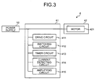
- Fig. 3 is a block diagram of the driving unit 4.
- the driving unit 4 includes a control circuit 41 and a drive mechanism 42.
- the control circuit 41 controls the drive mechanism 42.
- the control circuit 41 is connected to a power supply (a direct-current power supply) 10 of the vehicle.
- the drive mechanism 42 includes a motor 421 and a plurality of gears (not shown) that is connected to the motor 421.
- the drive mechanism 42 causes the body unit 3 to rotate with respect to the base unit 2 by transmitting a rotation force of the motor 421 to the body unit 3 via the gears.
- the body unit 3 When the mirror 32 is in use, the body unit 3 is set in a set position at a predetermined angle with respect to the vehicle door so that a driver of the vehicle can have a clear view from the mirror 32.
- the driver To retract the mirror 32, the driver performs a switch operation from inside the vehicle to drive the driving unit 4. Then, the driving unit 4 drives the body unit 3 to rotate to a predetermined retracted position.
- the driver also performs a switch operation from inside the vehicle, and the driving unit 4 drives the body unit 3 to rotate to the set position.
- the control circuit 41 includes a drive circuit 411, a switching circuit 412, a timer circuit 413, a current detecting circuit 414, and an amplifying circuit 415 (see Fig. 3).
- the drive circuit 411 is used for turning ON the switching circuit 412.
- the switching circuit 412 is used for switching ON/OFF current supply to the motor 421. Specifically, when the switching circuit 412 is turned ON, a current is supplied to the motor 421, and thereby causing the motor 421 to rotate. On the contrary, when the switching circuit 412 is turned OFF, the current supply to the motor 421 is cut off, so that the motor 421 stops rotating.
- the timer circuit 413 is used for defining a predetermined set time to turn OFF the switching circuit 412.
- the current detecting circuit 414 is used for detecting whether a current fluctuation (of a motor current) occurs due to the rotation of the motor 421.
- the amplifying circuit 415 is used for amplifying the current fluctuation detected by the current detecting circuit 414, and outputting the amplified current fluctuation to the timer circuit 413.
- the current detecting circuit 414 is configured to detect the current fluctuation constantly.
- the amplifying circuit 415 amplifies a detection signal of the current fluctuation, and outputs the amplified detection signal to the timer circuit 413 as an ON/OFF signal.
- the timer circuit 413 (for defining the set time to turn OFF the switching circuit 412) is configured to be reset periodically. A time interval to reset the timer circuit 413 is shorter than the set time, so that the switching circuit 412 can keep the current supply to the motor 421 ON. Therefore, the motor 421 keeps rotating.
- the timer circuit 413 is not reset.
- the switching circuit 412 switches OFF the current supply to the motor 421, and the current supply to the motor 421 is cut off, and then the motor 421 stops rotating. In this manner, when the motor 421 is locked, the current supply to the motor 421 can be cut off. Thus, it is possible to prevent an occurrence of damage to the motor 421 (for example, an occurrence of huge thermal stress on a coil of the motor 421).
- the current fluctuation due to the rotation of the motor 421 is detected to determine whether the motor 421 rotates or is locked. Based on a result of the determination, the switching circuit 412 switches ON/OFF the current supply to the motor 421. Therefore, when the motor 421 is locked, the current supply to the motor 421 can be cut off reliably, and thus the motor 421 can be protected from overcurrent.
- a conventional vehicle mirror device turns ON/OFF a switching circuit (current supply to a motor) by determining whether a motor rotates based on a current difference between currents obtained when the motor rotates and when the motor is locked.
- the conventional vehicle mirror device cannot properly determine whether the motor rotates.
- the vehicle mirror device 1 can properly determine whether the motor 421 rotates regardless of a current value of the motor 421.
- the current supply to the motor 421 can be cut off when the motor 421 is locked.
- the timer circuit 413 is reset periodically, and thus the current can be kept supplied to the motor 421. Therefore, even when a load on the motor 421 fluctuates suddenly, the vehicle mirror device 1 can properly determine whether the motor 421 rotates, as compared with the conventional vehicle mirror device in which whether the motor rotates is determined based on the current difference.
- Fig. 4 is a circuit diagram of the control circuit 41.
- an upper line of the control circuit 41 is connected to a positive pole of the power supply 10, and a lower line of the control circuit 41 is connected to a negative pole of the power supply 10 (see Fig. 4).
- the upper line of the control circuit 41 is connected to the negative pole of the power supply 10
- the lower line of the control circuit 41 is connected to the positive pole of the power supply 10.
- the drive circuit 411 includes a zener diode ZD1 and a resistance R3 (for the upper stage, a zener diode ZD2 and the resistance R3).
- the switching circuit 412 is turned ON via the drive circuit 411.
- the motor 421 is supplied with current, and is driven to rotate.
- a switching element FET1 for the upper stage, a switching element FET2 in the switching circuit 412 is turned ON by the action of the zener diode ZD1 (for the upper stage, the zener diode ZD2).
- the switching circuit 412 includes the switching element FET1 (the switching element FET2).
- the switching element FET1 When the switching element FET1 is turned ON, the current is supplied to the motor 421, and then the motor 421 is driven to rotate.
- the switching element FET1 When the switching element FET1 is turned OFF, the current supply to the motor 421 is cut off, and then the motor 421 stops rotating. In this manner, the current supply to the motor 421 can be switched ON/OFF.
- the timer circuit 413 includes a resistance R4, a capacitor C1, a zener diode ZD3, and a transistor Tr1 (for the upper stage, a resistance R5, a capacitor C2, a zener diode ZD4, and a transistor Tr2).
- the transistor Tr1 When the capacitor C1 is charged at a predetermined set voltage by the action of the zener diode ZD3, the transistor Tr1 is turned ON. Then, the switching element FET1 is turned OFF, and the current supply to the motor 421 is cut off, and then the motor 421 stops rotating.
- the transistor Tr1 is kept OFF. Namely, the current is supplied to the motor 421, so that the motor 421 keeps rotating.
- the amplifying circuit 415 includes resistances R10 and R11, and a transistor Tr7 (for the upper stage, resistances R12 and R13, and a transistor Tr8).
- the amplifying circuit 415 amplifies the received current fluctuation of the motor 421.
- the amplifies current fluctuation is converted into an ON/OFF signal by a transistor Tr3 (for the upper stage, a transistor Tr4), and the ON/OFF signal is output to the timer circuit 413.
- a current fluctuation (such as a current fluctuation due to a change of a relative position between a stator magnet and a rotor coil, or a current fluctuation due to a change of a current phase) occurs in a waveform of a detected current (see Fig. 5).
- the current fluctuation is detected by the current detecting circuit 414, and then the detected current fluctuation is amplified by the amplifying circuit 415. Then, the amplified current fluctuation is converted into an ON/OFF signal by the transistor Tr3 (for the upper stage, the transistor Tr4), and the ON/OFF signal is input to the timer circuit 413.
- the capacitor C1 (for the upper stage, the capacitor C2) is discharged, and then the timer circuit 413 is reset.
- the capacitor C1 is not charged at the set voltage because the timer circuit 413 is reset periodically, so that the transistor Tr1 is kept OFF. Namely, the switching element FET1 is kept ON, so that the motor 421 keeps rotating.
- the control circuit 41 (the current detecting circuit 414) detects a current fluctuation that occurs due to the rotation of the motor 421. When no current fluctuation is detected, it is determined that the motor 421 is locked, and the switching circuit 412 switches OFF the current supply to the motor 421. Consequently, the current supply to the motor 421 is cut off, and thus the motor 421 can be protected from overcurrent.
- the current fluctuation occurs as long as the motor 421 rotates even if a rotating speed of the motor 421 is low. Therefore, in case the motor 421 falls into an overcurrent state due to a sudden overload on the motor 421, the switching circuit 412 may keep switching ON the current supply to the motor 421, and thus the motor 421 may keep rotating. Also, in case the switching circuit 412 has any damage, the motor 421 may keep rotating.
- a positive temperature coefficient (PTC) thermistor is provided in the control circuit 41 (see Fig. 4).
- the PTC thermistor is connected in series with the control circuit 41.
- the PTC thermistor amplifies its resistance, and thereby developing a heat.
- a load on the motor 421 due to the overcurrent is reduced, and thus the motor 421 can be protected from the overcurrent.
- an applied voltage to the control circuit 41 may be degraded, and thereby causing the control circuit 41 to fall into an unstable condition.
- the control circuit 41 (the current detecting circuit 414) includes the shunt resistance R1 (the shunt resistance R2) for detecting the current fluctuation of the motor 421
- the shunt resistance R1 (the shunt resistance R2) preferably includes a PTC thermistor PTC1 (for the upper stage, a PTC thermistor PTC2) as shown in Fig. 6.
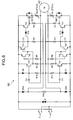
- Fig. 6 is a circuit diagram of a control circuit 641 according to a first modification of the embodiment. The portions identical to those in Fig. 4 for the control circuit 41 are denoted with the same reference numerals, and the description of those portions is omitted.
- the PTC thermistor is connected in series with the control circuit 41 (see Fig.
- the shunt resistance R1 (for the upper stage, the shunt resistance R2) includes the PTC thermistor PTC1 (for the upper stage, the PTC thermistor PTC2) instead of providing the PTC thermistor.
- the switching circuit 412 keeps switching ON the current supply to the motor 421, and thus the motor 421 keeps rotating.
- the switching circuit 412 switches OFF the current supply to the motor 421, and the current supply to the motor 421 is cut off, and then the motor 421 stops rotating.
- the motor 421 can be protected from the overcurrent.
- the shunt resistance R1 (for the upper stage, the shunt resistance R2) includes the PTC thermistor PTC1 (for the upper stage, the PTC thermistor PTC2), so that the shunt resistance R1 (for the upper stage, the shunt resistance R2) causes a development of heat, and thereby increasing its resistance value.
- an applied voltage to the motor 421 is degraded, and then the motor 421 stops rotating.
- the control circuit 641 in which the shunt resistance R1 (for the upper stage, the shunt resistance R2) includes the PTC thermistor PTC1 (for the upper stage, the PTC thermistor PTC2), even if the applied voltage to the motor 421 is degraded, the applied voltage to the control circuit 641 hardly fluctuates by the action of the PTC thermistor PTC1 (for the upper stage, the PTC thermistor PTC2) (the shunt resistance R1 (for the upper stage, the shunt resistance R2)) as compared with the control circuit 41 in which the shunt resistance R1 (for the upper stage, the shunt resistance R2) and the PTC thermistor are separately arranged (see Fig. 4).
- the control circuit 641 can operate stably.
- the control circuit 641 includes the first current detecting circuit 414 to be used when the mirror 32 is retracted and the second current detecting circuit 414 to be used when the mirror 32 is set up.
- the first and second current detecting circuits 414 are arranged symmetrically, and connected to the motor 421.
- the shunt resistances R1 and R2 of the first and second current detecting circuits 414 respectively include the PTC thermistors PTC1 and PTC2.
- the control circuit 641 when the current is supplied to the motor 421, the current flows in both of the PTC thermistors PTC1 and PTC2 (the shunt resistances R1 and R2). Therefore, in case a current value of the motor 421 increases due to a decrease of the rotating speed of the motor 421, any one of the PTC thermistors PTC1 and PTC2 that causes a development of heat earlier is activated. Moreover, the PTC thermistors PTC1 and PTC2 (the shunt resistances R1 and R2) are respectively arranged in each of the symmetrically-arranged current detecting circuits 414, so that a design of the control circuit 641 can be simplified.
- either one of the shunt resistances R1 and R2 can include the PTC thermistor PTC1 or PTC2 as shown in Fig. 7.
- Fig. 7 is a circuit diagram of a control circuit 741 according to a second modification of the embodiment. In the control circuit 741, only the shunt resistance R1 includes the PTC thermistor PTC1. Even though the shunt resistance R2 does not include the PTC thermistor PTC2, the control circuit 741 can operate stably.
- control circuit 641 includes the first and second current detecting circuits 414.
- the first and second current detecting circuits 414 include the shunt resistances R1 and R2, respectively, for detecting the current fluctuation of the motor 421.
- a diode is connected in parallel to the shunt resistance as shown in Fig. 8.
- Fig. 8 is a circuit diagram of a control circuit 841 according to a third modification of the embodiment.
- a diode D3 is connected in parallel to the shunt resistance R1 of the first current detecting circuit 414, and a diode D4 is connected in parallel to the shunt resistance R2 of the second current detecting circuit 414.
- the diodes D3 and D4 are arranged in such a manner that the current to flow into the shunt resistance R2 is cut off while the current is flowing into the shunt resistance R1, and vice versa.
- the shunt resistance R1 is connected in series with the switching element FET1 of the switching circuit 412.
- the diode D3 is connected in parallel to the shunt resistance R1 and the switching element FET1.
- the shunt resistance R2 is connected in series with the switching element FET2 of the switching circuit 412.
- the diode D4 is connected in parallel to the shunt resistance R2 and the switching element FET2.
- the diodes D3 and D4 are arranged in such a manner that when the current is supplied to the shunt resistance R1 (or the shunt resistance R2) and the switching element FET1 (or the switching element FET2), the current supply to the shunt resistance R2 (or the shunt resistance R1) and the switching element FET2 (or the switching element FET1) is cut off. Therefore, when the mirror 32 is retracted or set up, the current does not flow in both of the shunt resistances R1 and R2.
- the shunt resistances R1 and R2 of the first and second current detecting circuits 414 include the PTC thermistor PTC1 and the PTC thermistor PTC2, respectively, as shown in Fig. 8.
- the control circuit 841 can operate stably.
- a voltage applied to the motor decreases, a voltage applied to a control circuit hardly fluctuates by the action of a PTC thermistor.
- the control circuit can operate stably.
Landscapes
- Engineering & Computer Science (AREA)
- Multimedia (AREA)
- Mechanical Engineering (AREA)
- Rear-View Mirror Devices That Are Mounted On The Exterior Of The Vehicle (AREA)
Abstract
Description
- The present application claims priority to and incorporates by reference the entire contents of
Japanese priority document, 2006-239035 Japanese priority document, 2007-111885 - The present invention relates to a vehicle mirror device.
- In conventional vehicle mirror devices used for, for example, power retractable side mirrors, when a mirror is retracted to a retracted position, a driving motor is locked. When supplied with current, the driving motor is driven to rotate even if it is being locked. As a result, the driving motor may be damaged. Therefore, there is a need of a technology for cutting off current supply to the driving motor immediately when the driving motor is locked.
- For example, a conventional vehicle mirror device disclosed in
Japanese Patent Application Laid-open No. 2005-306277 - It is an object of the present invention to at least partially solve the problems in the conventional technology.
- According to an aspect of the present invention, a vehicle mirror device includes a base unit that is configured to be fixed to a vehicle, a body unit that includes a mirror and is rotatably attached to the base unit, and a driving unit that drives the body unit to rotate with respect to the base unit. The driving unit includes a motor that applies a driving force to the body unit to rotate the body unit, a current detecting circuit that detects current fluctuation that occurs due to rotation of the motor, and a switching circuit that switches ON or OFF current supply to the motor. While the current detecting circuit detects current fluctuation, the switching circuit keeps the current supply ON. When the current detecting circuit detects no current fluctuation, the switching circuit switches OFF the current supply.
- The above and other objects, features, advantages and technical and industrial significance of this invention will be better understood by reading the following detailed description of presently preferred embodiments of the invention, when considered in connection with the accompanying drawings.
-
- Fig. 1 is a schematic diagram of a vehicle mirror device according to an embodiment of the present invention;
- Fig. 2 is a schematic diagram for explaining movement of the vehicle mirror device shown in Fig: 1;
- Fig. 3 is a block diagram of a driving unit shown in Fig. 1;
- Fig. 4 is a circuit diagram of a control circuit shown in Fig. 3;
- Fig. 5 is a graph of currents caused by the rotation of a motor shown in Fig. 3;
- Fig. 6 is a circuit diagram of a control circuit according to a first modification of the embodiment;
- Fig. 7 is a circuit diagram of a control circuit according to a second modification of the embodiment; and
- Fig. 8 is a circuit diagram of a control circuit according to a third modification of the embodiment.
- Exemplary embodiments of the present invention are explained in detail below with reference to the accompanying drawings. The present invention is not limited to the embodiments.
- Figs. 1 and 2 are schematic diagrams of a
vehicle mirror device 1 according to an embodiment of the present invention. Thevehicle mirror device 1 is explained as being applied to, but not limited to, a power retractable side mirror of a vehicle. Thevehicle mirror device 1 includes abase unit 2, abody unit 3, and adriving unit 4. Thebase unit 2 is configured to be fixed to a vehicle door (not shown). Thebody unit 3 includes amirror housing 31 and amirror 32 that is fitted in themirror housing 31, and is rotatably attached to the base unit 2 (see Fig. 2). Thedriving unit 4 drives thebody unit 3 to rotate with respect to thebase unit 2, and is housed in themirror housing 31. - Fig. 3 is a block diagram of the
driving unit 4. Thedriving unit 4 includes acontrol circuit 41 and adrive mechanism 42. Thecontrol circuit 41 controls thedrive mechanism 42. Thecontrol circuit 41 is connected to a power supply (a direct-current power supply) 10 of the vehicle. Thedrive mechanism 42 includes amotor 421 and a plurality of gears (not shown) that is connected to themotor 421. Thedrive mechanism 42 causes thebody unit 3 to rotate with respect to thebase unit 2 by transmitting a rotation force of themotor 421 to thebody unit 3 via the gears. - When the
mirror 32 is in use, thebody unit 3 is set in a set position at a predetermined angle with respect to the vehicle door so that a driver of the vehicle can have a clear view from themirror 32. To retract themirror 32, the driver performs a switch operation from inside the vehicle to drive thedriving unit 4. Then, thedriving unit 4 drives thebody unit 3 to rotate to a predetermined retracted position. To use themirror 32, the driver also performs a switch operation from inside the vehicle, and thedriving unit 4 drives thebody unit 3 to rotate to the set position. - The
control circuit 41 includes adrive circuit 411, aswitching circuit 412, atimer circuit 413, a current detectingcircuit 414, and an amplifying circuit 415 (see Fig. 3). Thedrive circuit 411 is used for turning ON theswitching circuit 412. Theswitching circuit 412 is used for switching ON/OFF current supply to themotor 421. Specifically, when theswitching circuit 412 is turned ON, a current is supplied to themotor 421, and thereby causing themotor 421 to rotate. On the contrary, when theswitching circuit 412 is turned OFF, the current supply to themotor 421 is cut off, so that themotor 421 stops rotating. Thetimer circuit 413 is used for defining a predetermined set time to turn OFF theswitching circuit 412. Thecurrent detecting circuit 414 is used for detecting whether a current fluctuation (of a motor current) occurs due to the rotation of themotor 421. The amplifyingcircuit 415 is used for amplifying the current fluctuation detected by thecurrent detecting circuit 414, and outputting the amplified current fluctuation to thetimer circuit 413. - While the
motor 421 rotates (except when themirror 32 is set in the retracted position or the set position, i.e., themotor 421 is locked), a current fluctuation occurs due to the rotation of themotor 421. On the other hand, when themirror 32 is set in the retracted position or the set position, i.e., when themotor 421 is locked, no current fluctuation occurs. - The current detecting
circuit 414 is configured to detect the current fluctuation constantly. When the current fluctuation is detected by the current detectingcircuit 414, the amplifyingcircuit 415 amplifies a detection signal of the current fluctuation, and outputs the amplified detection signal to thetimer circuit 413 as an ON/OFF signal. The timer circuit 413 (for defining the set time to turn OFF the switching circuit 412) is configured to be reset periodically. A time interval to reset thetimer circuit 413 is shorter than the set time, so that theswitching circuit 412 can keep the current supply to themotor 421 ON. Therefore, themotor 421 keeps rotating. - When the
motor 421 is locked, no current fluctuation is detected. Therefore, thetimer circuit 413 is not reset. As a result, when the set time has elapsed, theswitching circuit 412 switches OFF the current supply to themotor 421, and the current supply to themotor 421 is cut off, and then themotor 421 stops rotating. In this manner, when themotor 421 is locked, the current supply to themotor 421 can be cut off. Thus, it is possible to prevent an occurrence of damage to the motor 421 (for example, an occurrence of huge thermal stress on a coil of the motor 421). - As described above, in the
vehicle mirror device 1, the current fluctuation due to the rotation of themotor 421 is detected to determine whether themotor 421 rotates or is locked. Based on a result of the determination, theswitching circuit 412 switches ON/OFF the current supply to themotor 421. Therefore, when themotor 421 is locked, the current supply to themotor 421 can be cut off reliably, and thus themotor 421 can be protected from overcurrent. - For example, a conventional vehicle mirror device turns ON/OFF a switching circuit (current supply to a motor) by determining whether a motor rotates based on a current difference between currents obtained when the motor rotates and when the motor is locked. However, if the current difference is slight because of a performance of the motor, the conventional vehicle mirror device cannot properly determine whether the motor rotates. On the other hand, the
vehicle mirror device 1 can properly determine whether themotor 421 rotates regardless of a current value of themotor 421. - According to the embodiment, the current supply to the
motor 421 can be cut off when themotor 421 is locked. Thus, it is possible to reduce the unnecessary current supply to themotor 421 as compared with a case where current supply to a motor is defined by only a set time of a timer circuit simply. - Furthermore, while the current fluctuation is detected, the
timer circuit 413 is reset periodically, and thus the current can be kept supplied to themotor 421. Therefore, even when a load on themotor 421 fluctuates suddenly, thevehicle mirror device 1 can properly determine whether themotor 421 rotates, as compared with the conventional vehicle mirror device in which whether the motor rotates is determined based on the current difference. - Fig. 4 is a circuit diagram of the
control circuit 41. When themirror 32 is to be retracted (or to be set up), an upper line of thecontrol circuit 41 is connected to a positive pole of thepower supply 10, and a lower line of thecontrol circuit 41 is connected to a negative pole of the power supply 10 (see Fig. 4). On the contrary, when themirror 32 is to be set up (or to be retracted), the upper line of thecontrol circuit 41 is connected to the negative pole of thepower supply 10, and the lower line of thecontrol circuit 41 is connected to the positive pole of thepower supply 10. A case where the upper line of thecontrol circuit 41 is connected to the positive pole of thepower supply 10 is explained below. - The
drive circuit 411 includes a zener diode ZD1 and a resistance R3 (for the upper stage, a zener diode ZD2 and the resistance R3). When themirror 32 is to be retracted (or to be set up), theswitching circuit 412 is turned ON via thedrive circuit 411. Then, themotor 421 is supplied with current, and is driven to rotate. At the same time, a switching element FET1 (for the upper stage, a switching element FET2) in theswitching circuit 412 is turned ON by the action of the zener diode ZD1 (for the upper stage, the zener diode ZD2). - The
switching circuit 412 includes the switching element FET1 (the switching element FET2). When the switching element FET1 is turned ON, the current is supplied to themotor 421, and then themotor 421 is driven to rotate. When the switching element FET1 is turned OFF, the current supply to themotor 421 is cut off, and then themotor 421 stops rotating. In this manner, the current supply to themotor 421 can be switched ON/OFF. - The
timer circuit 413 includes a resistance R4, a capacitor C1, a zener diode ZD3, and a transistor Tr1 (for the upper stage, a resistance R5, a capacitor C2, a zener diode ZD4, and a transistor Tr2). When the capacitor C1 is charged at a predetermined set voltage by the action of the zener diode ZD3, the transistor Tr1 is turned ON. Then, the switching element FET1 is turned OFF, and the current supply to themotor 421 is cut off, and then themotor 421 stops rotating. When the capacitor C1 is not charged at the set voltage because thetimer circuit 413 is reset, the transistor Tr1 is kept OFF. Namely, the current is supplied to themotor 421, so that themotor 421 keeps rotating. - The current detecting
circuit 414 includes a shunt resistance R1 and a capacitor C3 (for the upper stage, a shunt resistance R2 and a capacitor C4). The current detectingcircuit 414 obtains a current fluctuation (see Fig. 5) that occurs due to the rotation of themotor 421 through the shunt resistance R1 and the capacitor C3, and outputs the obtained current fluctuation to the amplifyingcircuit 415. - The amplifying
circuit 415 includes resistances R10 and R11, and a transistor Tr7 (for the upper stage, resistances R12 and R13, and a transistor Tr8). The amplifyingcircuit 415 amplifies the received current fluctuation of themotor 421. The amplifies current fluctuation is converted into an ON/OFF signal by a transistor Tr3 (for the upper stage, a transistor Tr4), and the ON/OFF signal is output to thetimer circuit 413. - While the
mirror 32 is retracted (or set up), when thecontrol circuit 41 is connected to thepower supply 10, a current is supplied to themotor 421 via thedrive circuit 411, and then themotor 421 rotates. At this time, when the upper line of thecontrol circuit 41 shown in Fig. 4 is connected to the positive pole of thepower supply 10, the current passes through an internal diode of the switching element FET2, the shunt resistance R2, themotor 421, the shunt resistance R1, and the switching element FET1 in this order. Then, the current flows to themotor 421, whereby themotor 421 rotates. At this time, the current is flowing in the zener diode ZD1 via the resistance R3, and the switching element FET1 is ON. - While the
motor 421 rotates, a current fluctuation (such as a current fluctuation due to a change of a relative position between a stator magnet and a rotor coil, or a current fluctuation due to a change of a current phase) occurs in a waveform of a detected current (see Fig. 5). The current fluctuation is detected by the current detectingcircuit 414, and then the detected current fluctuation is amplified by the amplifyingcircuit 415. Then, the amplified current fluctuation is converted into an ON/OFF signal by the transistor Tr3 (for the upper stage, the transistor Tr4), and the ON/OFF signal is input to thetimer circuit 413. If the ON/OFF signal indicates an ON signal, the capacitor C1 (for the upper stage, the capacitor C2) is discharged, and then thetimer circuit 413 is reset. The capacitor C1 is not charged at the set voltage because thetimer circuit 413 is reset periodically, so that the transistor Tr1 is kept OFF. Namely, the switching element FET1 is kept ON, so that themotor 421 keeps rotating. - On the other hand, while the
motor 421 is locked (i.e., thebody unit 3 is set in the set position or the retracted position), no current fluctuation occurs because themotor 421 does not rotate. Therefore, the waveform of the detected current indicates a constant current, so that the ON/OFF signal indicating an OFF signal only is input to thetimer circuit 413 via the transistor Tr3 (for the upper stage, the transistor Tr4). Therefore, the capacitor C1 (for the upper stage, the capacitor C2) is charged at the set voltage by the zener diode ZD3, and then the transistor Tr1 is turned ON. Consequently, the switching element FET1 is turned OFF, and the current supply to themotor 421 is cut off, and then themotor 421 stops rotating. - When the switching element FET1 is turned OFF, a potential of the shunt resistance R1 (for the upper stage, the shunt resistance R2) is surged, so that the transistor Tr5 (for the upper stage, the transistor Tr6) is turned ON, and the transistor Tr3 (for the upper stage, the transistor Tr4) is latched in the OFF state.
- In the
vehicle mirror device 1, the control circuit 41 (the current detecting circuit 414) detects a current fluctuation that occurs due to the rotation of themotor 421. When no current fluctuation is detected, it is determined that themotor 421 is locked, and theswitching circuit 412 switches OFF the current supply to themotor 421. Consequently, the current supply to themotor 421 is cut off, and thus themotor 421 can be protected from overcurrent. - However, the current fluctuation occurs as long as the
motor 421 rotates even if a rotating speed of themotor 421 is low. Therefore, in case themotor 421 falls into an overcurrent state due to a sudden overload on themotor 421, theswitching circuit 412 may keep switching ON the current supply to themotor 421, and thus themotor 421 may keep rotating. Also, in case theswitching circuit 412 has any damage, themotor 421 may keep rotating. - To protect the
motor 421 from the overcurrent, a positive temperature coefficient (PTC) thermistor is provided in the control circuit 41 (see Fig. 4). The PTC thermistor is connected in series with thecontrol circuit 41. Upon occurrence of the overcurrent, the PTC thermistor amplifies its resistance, and thereby developing a heat. As a result, a load on themotor 421 due to the overcurrent is reduced, and thus themotor 421 can be protected from the overcurrent. - However, in transition to the PTC thermistor, an applied voltage to the
control circuit 41 may be degraded, and thereby causing thecontrol circuit 41 to fall into an unstable condition. - Therefore, in a case where the control circuit 41 (the current detecting circuit 414) includes the shunt resistance R1 (the shunt resistance R2) for detecting the current fluctuation of the
motor 421, the shunt resistance R1 (the shunt resistance R2) preferably includes a PTC thermistor PTC1 (for the upper stage, a PTC thermistor PTC2) as shown in Fig. 6. Fig. 6 is a circuit diagram of acontrol circuit 641 according to a first modification of the embodiment. The portions identical to those in Fig. 4 for thecontrol circuit 41 are denoted with the same reference numerals, and the description of those portions is omitted. In thecontrol circuit 41, the PTC thermistor is connected in series with the control circuit 41 (see Fig. 4). In thecontrol circuit 641, the shunt resistance R1 (for the upper stage, the shunt resistance R2) includes the PTC thermistor PTC1 (for the upper stage, the PTC thermistor PTC2) instead of providing the PTC thermistor. - While the
motor 421 is driven to rotate, the current fluctuation, which occurs due to the rotation of themotor 421, is detected via the shunt resistance R1 (for the upper stage, the shunt resistance R2). While the current fluctuation is detected, the switching circuit 412 (the switching element FET1) keeps switching ON the current supply to themotor 421, and thus themotor 421 keeps rotating. When no current fluctuation is detected, theswitching circuit 412 switches OFF the current supply to themotor 421, and the current supply to themotor 421 is cut off, and then themotor 421 stops rotating. Thus, themotor 421 can be protected from the overcurrent. - If the rotating speed of the
motor 421 decreases, for example, due to an increase of a load on themotor 421, a current value of themotor 421 increases. In this case, the shunt resistance R1 (for the upper stage, the shunt resistance R2) includes the PTC thermistor PTC1 (for the upper stage, the PTC thermistor PTC2), so that the shunt resistance R1 (for the upper stage, the shunt resistance R2) causes a development of heat, and thereby increasing its resistance value. As a result, an applied voltage to themotor 421 is degraded, and then themotor 421 stops rotating. Therefore, no current fluctuation occurs because themotor 421 stops rotating, and theswitching circuit 412 switches OFF the current supply to themotor 421, i.e., the current supply to themotor 421 is cut off. Thus, themotor 421 can be protected from the overcurrent. - In the
control circuit 641 in which the shunt resistance R1 (for the upper stage, the shunt resistance R2) includes the PTC thermistor PTC1 (for the upper stage, the PTC thermistor PTC2), even if the applied voltage to themotor 421 is degraded, the applied voltage to thecontrol circuit 641 hardly fluctuates by the action of the PTC thermistor PTC1 (for the upper stage, the PTC thermistor PTC2) (the shunt resistance R1 (for the upper stage, the shunt resistance R2)) as compared with thecontrol circuit 41 in which the shunt resistance R1 (for the upper stage, the shunt resistance R2) and the PTC thermistor are separately arranged (see Fig. 4). Thus, thecontrol circuit 641 can operate stably. - The
control circuit 641 includes the first current detectingcircuit 414 to be used when themirror 32 is retracted and the second current detectingcircuit 414 to be used when themirror 32 is set up. The first and second current detectingcircuits 414 are arranged symmetrically, and connected to themotor 421. The shunt resistances R1 and R2 of the first and second current detectingcircuits 414 respectively include the PTC thermistors PTC1 and PTC2. - In the
control circuit 641, when the current is supplied to themotor 421, the current flows in both of the PTC thermistors PTC1 and PTC2 (the shunt resistances R1 and R2). Therefore, in case a current value of themotor 421 increases due to a decrease of the rotating speed of themotor 421, any one of the PTC thermistors PTC1 and PTC2 that causes a development of heat earlier is activated. Moreover, the PTC thermistors PTC1 and PTC2 (the shunt resistances R1 and R2) are respectively arranged in each of the symmetrically-arranged current detectingcircuits 414, so that a design of thecontrol circuit 641 can be simplified. - Alternatively, either one of the shunt resistances R1 and R2 can include the PTC thermistor PTC1 or PTC2 as shown in Fig. 7. Fig. 7 is a circuit diagram of a
control circuit 741 according to a second modification of the embodiment. In thecontrol circuit 741, only the shunt resistance R1 includes the PTC thermistor PTC1. Even though the shunt resistance R2 does not include the PTC thermistor PTC2, thecontrol circuit 741 can operate stably. - As described above, the
control circuit 641 includes the first and second current detectingcircuits 414. The first and second current detectingcircuits 414 include the shunt resistances R1 and R2, respectively, for detecting the current fluctuation of themotor 421. - However, with the configuration of the
control circuit 641, when thevehicle mirror device 1 is in use, the current flows in both of the shunt resistances R1 and R2, so that a voltage drop occurs in both of the shunt resistances R1 and R2. Therefore, a voltage to be supplied to themotor 421 is wasted. - To solve the problem, a diode is connected in parallel to the shunt resistance as shown in Fig. 8. Fig. 8 is a circuit diagram of a
control circuit 841 according to a third modification of the embodiment. In thecontrol circuit 841, a diode D3 is connected in parallel to the shunt resistance R1 of the first current detectingcircuit 414, and a diode D4 is connected in parallel to the shunt resistance R2 of the second current detectingcircuit 414. The diodes D3 and D4 are arranged in such a manner that the current to flow into the shunt resistance R2 is cut off while the current is flowing into the shunt resistance R1, and vice versa. - For example, in the first current detecting
circuit 414, which is used when themirror 32 is retracted, the shunt resistance R1 is connected in series with the switching element FET1 of theswitching circuit 412. The diode D3 is connected in parallel to the shunt resistance R1 and the switching element FET1. In the same manner as the first current detectingcircuit 414, in the second current detectingcircuit 414, which is used when themirror 32 is set up, the shunt resistance R2 is connected in series with the switching element FET2 of theswitching circuit 412. The diode D4 is connected in parallel to the shunt resistance R2 and the switching element FET2. - The diodes D3 and D4 are arranged in such a manner that when the current is supplied to the shunt resistance R1 (or the shunt resistance R2) and the switching element FET1 (or the switching element FET2), the current supply to the shunt resistance R2 (or the shunt resistance R1) and the switching element FET2 (or the switching element FET1) is cut off. Therefore, when the
mirror 32 is retracted or set up, the current does not flow in both of the shunt resistances R1 and R2. - In this manner, when the
mirror 32 is retracted (or themirror 32 is set up), the current flows in only the shunt resistance R1 (or the shunt resistance R2). Therefore, an occurrence of the voltage drop due to the shunt resistances R1 and R2 can be reduced as compared with the case of thecontrol circuit 641 in which the current flows in both of the shunt resistances R1 and R2. Thus, in thecontrol circuit 841, a voltage can be supplied to themotor 421 efficiently. - As in the other modifications, it is preferable that the shunt resistances R1 and R2 of the first and second current detecting
circuits 414 include the PTC thermistor PTC1 and the PTC thermistor PTC2, respectively, as shown in Fig. 8. By the action of the PTC thermistors PTC1 and PTC2, thecontrol circuit 841 can operate stably. - According to an aspect of the present invention, when a motor is locked, current supply to the motor can be appropriately cut off, and thus the motor can be protected from overcurrent. Even when a load on the motor fluctuates suddenly, whether the motor rotates can be properly determined.
- Moreover, even if a voltage applied to the motor decreases, a voltage applied to a control circuit hardly fluctuates by the action of a PTC thermistor. Thus, the control circuit can operate stably.
- Furthermore, when a mirror is retracted (or when the mirror is set up), current flows in either one of shunt resistances. Therefore, an occurrence of a voltage drop due to the shunt resistances can be reduced. Thus, a voltage can be supplied to the motor efficiently.
- Although the invention has been described with respect to a specific embodiment for a complete and clear disclosure, the appended claims are not to be thus limited but are to be construed as embodying all modifications and alternative constructions that may occur to one skilled in the art that fairly fall within the basic teaching herein set forth.
Claims (4)
- A vehicle mirror device comprising:a base unit (2) that is configured to be fixed to a vehicle;a body unit (3) that includes a mirror (32), and is rotatably attached to the base unit (2); anda driving unit (4) that drives the body unit (3) to rotate with respect to the base unit (2), wherein
the driving unit (4) includes
a motor (421) that applies a driving force to the body unit (3) to rotate the body unit (3);
a current detecting circuit (414) that detects current fluctuation that occurs due to rotation of the motor (421); and
a switching circuit (412) that switches ON or OFF current supply to the motor (421),while the current detecting circuit (414) detects current fluctuation, the switching circuit (412) keeps the current supply ON, andwhen the current detecting circuit (414) detects no current fluctuation, the switching circuit (412) switches OFF the current supply. - The vehicle mirror device according to claim 1, wherein
the driving unit (4) further includes a timer circuit (413) that defines a time to turn OFF the switching circuit (412), and
while the current detecting circuit (414) detects current fluctuation, the timer circuit (413) is reset. - The vehicle mirror device according to claim 1 or 2, wherein
the current detecting circuit (414) includes a shunt resistance for detecting current fluctuation, and
the shunt resistance includes a positive temperature coefficient thermistor. - The vehicle mirror device according to any one of claims 1 to 3, wherein
the current detecting circuit (414) includes a first current detecting circuit (414) used when the mirror (32) is retracted, and a second current detecting circuit (414) used when the mirror (32) is set up,
the first current detecting circuit (414) includes a first shunt resistance for detecting current fluctuation, and the second current detecting circuit (414) includes a second shunt resistance for detecting current fluctuation,
the driving unit (4) further includes a first diode connected in parallel to the first shunt resistance, and a second diode connected in parallel to the second shunt resistance, and
when a current flows in either one of the first shunt resistance and the second shunt resistance, current supply to other one of the first shunt resistance and the second shunt resistance is cut off by corresponding one of the first diode and the second diode.
Applications Claiming Priority (2)
| Application Number | Priority Date | Filing Date | Title |
|---|---|---|---|
| JP2006239035 | 2006-09-04 | ||
| JP2007111885A JP2008087754A (en) | 2006-09-04 | 2007-04-20 | Mirror device for vehicle |
Publications (2)
| Publication Number | Publication Date |
|---|---|
| EP1897752A1 true EP1897752A1 (en) | 2008-03-12 |
| EP1897752B1 EP1897752B1 (en) | 2010-05-26 |
Family
ID=38626431
Family Applications (1)
| Application Number | Title | Priority Date | Filing Date |
|---|---|---|---|
| EP07016777A Expired - Fee Related EP1897752B1 (en) | 2006-09-04 | 2007-08-27 | Vehicle mirror device |
Country Status (5)
| Country | Link |
|---|---|
| US (1) | US7759892B2 (en) |
| EP (1) | EP1897752B1 (en) |
| JP (1) | JP2008087754A (en) |
| KR (1) | KR100891898B1 (en) |
| DE (1) | DE602007006732D1 (en) |
Families Citing this family (10)
| Publication number | Priority date | Publication date | Assignee | Title |
|---|---|---|---|---|
| NL1032235C2 (en) * | 2006-07-26 | 2008-01-29 | Eaton Automotive Bv | Mirror adjustment mechanism, exterior mirror unit and method. |
| USD593468S1 (en) * | 2008-01-29 | 2009-06-02 | Chrysler Llc | Vehicle mirror |
| JP5262690B2 (en) * | 2008-12-25 | 2013-08-14 | 市光工業株式会社 | Door mirror control device |
| JP5522959B2 (en) * | 2009-03-13 | 2014-06-18 | 株式会社ミツバ | Motor drive circuit for vehicle door mirror |
| DE102010044292B4 (en) | 2010-09-03 | 2021-10-14 | Audi Ag | Method and movement device for moving an exterior mirror of a motor vehicle by an electric motor |
| US9449390B1 (en) * | 2015-05-19 | 2016-09-20 | Ford Global Technologies, Llc | Detecting an extended side view mirror |
| KR102463262B1 (en) * | 2017-12-14 | 2022-11-10 | 주식회사 에스엘미러텍 | Apparatus and method for operating control of vehicle mirror |
| KR102736468B1 (en) * | 2019-12-27 | 2024-11-29 | 주식회사 에스엘미러텍 | Controlling device of camera mirror for vehicle |
| US11279286B2 (en) * | 2020-04-15 | 2022-03-22 | Motherson Innovations Company Limited | Actuator assembly for mirror |
| CN111949051B (en) * | 2020-07-27 | 2023-03-14 | 江西久盛国际电力工程有限公司 | Automatic sun tracking control system and method for trough type heliostat field |
Citations (4)
| Publication number | Priority date | Publication date | Assignee | Title |
|---|---|---|---|---|
| DE3527906A1 (en) * | 1985-08-03 | 1987-02-12 | Keiper Recaro Gmbh Co | Circuit arrangement for positioning an object which can be adjusted by means of an adjusting device |
| JPH03193012A (en) * | 1989-12-24 | 1991-08-22 | Matsushita Electric Ind Co Ltd | Grinding equipment for coffee beans, etc. |
| JPH0767385A (en) * | 1993-08-25 | 1995-03-10 | Tokai Rika Co Ltd | Motor drive controller |
| GB2293152A (en) * | 1994-09-19 | 1996-03-20 | Murakami Kaimeido Kk | Control device for an electrically powered hinged rearview mirror for a vehicle |
Family Cites Families (10)
| Publication number | Priority date | Publication date | Assignee | Title |
|---|---|---|---|---|
| US4263536A (en) * | 1978-08-07 | 1981-04-21 | Clopay Corporation | Control circuit for a motor-driven door operator |
| DE3226614A1 (en) * | 1982-07-16 | 1984-01-19 | Robert Bosch Gmbh, 7000 Stuttgart | CIRCUIT ARRANGEMENT FOR INPUTING AND EXTENDING A MOTOR-DRIVEN ANTENNA |
| JP3200278B2 (en) * | 1994-03-16 | 2001-08-20 | マイクロン株式会社 | Motor controller |
| CA2143711A1 (en) * | 1994-12-30 | 1996-07-01 | Craig A. Miller | High voltage d-c current limiter |
| JPH0974780A (en) * | 1995-07-05 | 1997-03-18 | Tokai Rika Co Ltd | Stopping apparatus of driving gear to home position |
| JP2001287592A (en) * | 2000-04-06 | 2001-10-16 | Ichikoh Ind Ltd | Control circuit for electric retractable door mirror |
| US6960895B2 (en) * | 2003-03-20 | 2005-11-01 | Siemens Vdo Automotive Inc. | Coupled RFI choke as stall detection means for brush type DC motor |
| TWI232187B (en) * | 2003-06-28 | 2005-05-11 | Chaw Khong Co Ltd | Electrical operable pivoting back-mirror device |
| JP2005193889A (en) * | 2003-12-12 | 2005-07-21 | Tokai Rika Co Ltd | Motor control circuit for mirror arrangement |
| JP4199695B2 (en) * | 2004-04-23 | 2008-12-17 | 株式会社東海理化電機製作所 | Motor control circuit for mirror device |
-
2007
- 2007-04-20 JP JP2007111885A patent/JP2008087754A/en active Pending
- 2007-07-09 KR KR1020070068643A patent/KR100891898B1/en not_active Expired - Fee Related
- 2007-08-27 DE DE602007006732T patent/DE602007006732D1/en active Active
- 2007-08-27 US US11/892,809 patent/US7759892B2/en not_active Expired - Fee Related
- 2007-08-27 EP EP07016777A patent/EP1897752B1/en not_active Expired - Fee Related
Patent Citations (4)
| Publication number | Priority date | Publication date | Assignee | Title |
|---|---|---|---|---|
| DE3527906A1 (en) * | 1985-08-03 | 1987-02-12 | Keiper Recaro Gmbh Co | Circuit arrangement for positioning an object which can be adjusted by means of an adjusting device |
| JPH03193012A (en) * | 1989-12-24 | 1991-08-22 | Matsushita Electric Ind Co Ltd | Grinding equipment for coffee beans, etc. |
| JPH0767385A (en) * | 1993-08-25 | 1995-03-10 | Tokai Rika Co Ltd | Motor drive controller |
| GB2293152A (en) * | 1994-09-19 | 1996-03-20 | Murakami Kaimeido Kk | Control device for an electrically powered hinged rearview mirror for a vehicle |
Also Published As
| Publication number | Publication date |
|---|---|
| US7759892B2 (en) | 2010-07-20 |
| JP2008087754A (en) | 2008-04-17 |
| DE602007006732D1 (en) | 2010-07-08 |
| EP1897752B1 (en) | 2010-05-26 |
| KR20080021488A (en) | 2008-03-07 |
| US20080218888A1 (en) | 2008-09-11 |
| KR100891898B1 (en) | 2009-04-03 |
Similar Documents
| Publication | Publication Date | Title |
|---|---|---|
| EP1897752B1 (en) | Vehicle mirror device | |
| US8217608B2 (en) | Electric power supply device | |
| JP5144315B2 (en) | Drive circuit for brushless DC motor | |
| EP2006998A2 (en) | Load drive control circuit | |
| KR100923270B1 (en) | Mirror device for vehicle | |
| US20110188163A1 (en) | Abnormality detection circuit, load driving device, and electrical apparatus | |
| JP2011078228A (en) | Overcurrent protection circuit | |
| EP1974459B1 (en) | Systems and methods of monitoring a motor load | |
| CN100576717C (en) | Vehicle rearview mirror device | |
| EP1393976B1 (en) | Method for controlling motorized storing door mirror | |
| US5525878A (en) | Apparatus and method for controlling an electric motor | |
| JP5446249B2 (en) | Door mirror control device | |
| JP2007228704A (en) | Motor driver | |
| CN100454750C (en) | DC brushless motor driving device without Hall assembly | |
| JP4776251B2 (en) | Brushless motor drive circuit | |
| JP2008011662A (en) | Brushless motor drive device for outdoor fan of air conditioner | |
| JP2001339981A (en) | Control circuit for dc brushless motor | |
| JP2819863B2 (en) | Motor drive element protection method | |
| JP2010149655A (en) | Door mirror control device | |
| JP5262690B2 (en) | Door mirror control device | |
| JPH07312886A (en) | Dc motor controller | |
| JP2017063560A (en) | Brush motor | |
| KR19990070988A (en) | Overheat protection device of non-commutator motor | |
| JP2000308390A (en) | Rotation controller for dc brush motor | |
| JP2005069160A (en) | Motor-driven fan control device |
Legal Events
| Date | Code | Title | Description |
|---|---|---|---|
| PUAI | Public reference made under article 153(3) epc to a published international application that has entered the european phase |
Free format text: ORIGINAL CODE: 0009012 |
|
| 17P | Request for examination filed |
Effective date: 20080110 |
|
| AK | Designated contracting states |
Kind code of ref document: A1 Designated state(s): AT BE BG CH CY CZ DE DK EE ES FI FR GB GR HU IE IS IT LI LT LU LV MC MT NL PL PT RO SE SI SK TR |
|
| AX | Request for extension of the european patent |
Extension state: AL BA HR MK YU |
|
| 17Q | First examination report despatched |
Effective date: 20080429 |
|
| AKX | Designation fees paid |
Designated state(s): DE FR GB |
|
| GRAP | Despatch of communication of intention to grant a patent |
Free format text: ORIGINAL CODE: EPIDOSNIGR1 |
|
| GRAS | Grant fee paid |
Free format text: ORIGINAL CODE: EPIDOSNIGR3 |
|
| GRAA | (expected) grant |
Free format text: ORIGINAL CODE: 0009210 |
|
| AK | Designated contracting states |
Kind code of ref document: B1 Designated state(s): DE FR GB |
|
| REG | Reference to a national code |
Ref country code: GB Ref legal event code: FG4D |
|
| REF | Corresponds to: |
Ref document number: 602007006732 Country of ref document: DE Date of ref document: 20100708 Kind code of ref document: P |
|
| PGFP | Annual fee paid to national office [announced via postgrant information from national office to epo] |
Ref country code: FR Payment date: 20100824 Year of fee payment: 4 Ref country code: DE Payment date: 20100825 Year of fee payment: 4 |
|
| PLBE | No opposition filed within time limit |
Free format text: ORIGINAL CODE: 0009261 |
|
| STAA | Information on the status of an ep patent application or granted ep patent |
Free format text: STATUS: NO OPPOSITION FILED WITHIN TIME LIMIT |
|
| 26N | No opposition filed |
Effective date: 20110301 |
|
| REG | Reference to a national code |
Ref country code: DE Ref legal event code: R097 Ref document number: 602007006732 Country of ref document: DE Effective date: 20110228 |
|
| GBPC | Gb: european patent ceased through non-payment of renewal fee |
Effective date: 20110827 |
|
| REG | Reference to a national code |
Ref country code: FR Ref legal event code: ST Effective date: 20120430 |
|
| REG | Reference to a national code |
Ref country code: DE Ref legal event code: R119 Ref document number: 602007006732 Country of ref document: DE Effective date: 20120301 |
|
| PG25 | Lapsed in a contracting state [announced via postgrant information from national office to epo] |
Ref country code: FR Free format text: LAPSE BECAUSE OF NON-PAYMENT OF DUE FEES Effective date: 20110831 Ref country code: GB Free format text: LAPSE BECAUSE OF NON-PAYMENT OF DUE FEES Effective date: 20110827 |
|
| PG25 | Lapsed in a contracting state [announced via postgrant information from national office to epo] |
Ref country code: DE Free format text: LAPSE BECAUSE OF NON-PAYMENT OF DUE FEES Effective date: 20120301 |