EP1897623B1 - Dispenser assembly for a fluid dispensing receptacle and method of assembling same - Google Patents
Dispenser assembly for a fluid dispensing receptacle and method of assembling same Download PDFInfo
- Publication number
- EP1897623B1 EP1897623B1 EP07017311A EP07017311A EP1897623B1 EP 1897623 B1 EP1897623 B1 EP 1897623B1 EP 07017311 A EP07017311 A EP 07017311A EP 07017311 A EP07017311 A EP 07017311A EP 1897623 B1 EP1897623 B1 EP 1897623B1
- Authority
- EP
- European Patent Office
- Prior art keywords
- ferrule
- collar
- dispensing
- skirt
- dispensing assembly
- Prior art date
- Legal status (The legal status is an assumption and is not a legal conclusion. Google has not performed a legal analysis and makes no representation as to the accuracy of the status listed.)
- Active
Links
- 238000000034 method Methods 0.000 title claims description 16
- 239000012530 fluid Substances 0.000 title description 10
- 239000000463 material Substances 0.000 claims description 11
- 239000004033 plastic Substances 0.000 claims description 8
- 229910052782 aluminium Inorganic materials 0.000 claims description 4
- XAGFODPZIPBFFR-UHFFFAOYSA-N aluminium Chemical compound [Al] XAGFODPZIPBFFR-UHFFFAOYSA-N 0.000 claims description 4
- 239000004411 aluminium Substances 0.000 claims 1
- 230000008878 coupling Effects 0.000 claims 1
- 238000010168 coupling process Methods 0.000 claims 1
- 238000005859 coupling reaction Methods 0.000 claims 1
- 239000000126 substance Substances 0.000 claims 1
- 239000000047 product Substances 0.000 description 12
- 229910052751 metal Inorganic materials 0.000 description 11
- 239000002184 metal Substances 0.000 description 11
- 239000011521 glass Substances 0.000 description 9
- 239000000443 aerosol Substances 0.000 description 7
- 230000014759 maintenance of location Effects 0.000 description 6
- 239000007921 spray Substances 0.000 description 6
- 239000000428 dust Substances 0.000 description 4
- 238000009434 installation Methods 0.000 description 4
- 239000002304 perfume Substances 0.000 description 4
- 230000000717 retained effect Effects 0.000 description 4
- 230000006835 compression Effects 0.000 description 3
- 238000007906 compression Methods 0.000 description 3
- 238000007789 sealing Methods 0.000 description 3
- 239000003205 fragrance Substances 0.000 description 2
- 239000007788 liquid Substances 0.000 description 2
- 239000012263 liquid product Substances 0.000 description 2
- 238000004519 manufacturing process Methods 0.000 description 2
- 239000003595 mist Substances 0.000 description 2
- 238000003825 pressing Methods 0.000 description 2
- 230000001681 protective effect Effects 0.000 description 2
- 230000002829 reductive effect Effects 0.000 description 2
- 239000004743 Polypropylene Substances 0.000 description 1
- 244000273618 Sphenoclea zeylanica Species 0.000 description 1
- 230000000712 assembly Effects 0.000 description 1
- 238000000429 assembly Methods 0.000 description 1
- 239000011324 bead Substances 0.000 description 1
- 238000005452 bending Methods 0.000 description 1
- 230000009286 beneficial effect Effects 0.000 description 1
- 239000003086 colorant Substances 0.000 description 1
- 238000004891 communication Methods 0.000 description 1
- 239000012141 concentrate Substances 0.000 description 1
- 239000000470 constituent Substances 0.000 description 1
- 239000006071 cream Substances 0.000 description 1
- 238000002788 crimping Methods 0.000 description 1
- 230000001419 dependent effect Effects 0.000 description 1
- 230000000994 depressogenic effect Effects 0.000 description 1
- 230000000694 effects Effects 0.000 description 1
- 239000010408 film Substances 0.000 description 1
- 238000010348 incorporation Methods 0.000 description 1
- 238000002347 injection Methods 0.000 description 1
- 239000007924 injection Substances 0.000 description 1
- 230000007774 longterm Effects 0.000 description 1
- 238000000465 moulding Methods 0.000 description 1
- TWNQGVIAIRXVLR-UHFFFAOYSA-N oxo(oxoalumanyloxy)alumane Chemical compound O=[Al]O[Al]=O TWNQGVIAIRXVLR-UHFFFAOYSA-N 0.000 description 1
- 239000006072 paste Substances 0.000 description 1
- -1 polypropylene Polymers 0.000 description 1
- 229920001155 polypropylene Polymers 0.000 description 1
- 238000005086 pumping Methods 0.000 description 1
- 238000004064 recycling Methods 0.000 description 1
- 230000000284 resting effect Effects 0.000 description 1
- 230000000452 restraining effect Effects 0.000 description 1
- 238000009987 spinning Methods 0.000 description 1
- 229920005992 thermoplastic resin Polymers 0.000 description 1
- 239000010409 thin film Substances 0.000 description 1
Images


Classifications
-
- B—PERFORMING OPERATIONS; TRANSPORTING
- B05—SPRAYING OR ATOMISING IN GENERAL; APPLYING FLUENT MATERIALS TO SURFACES, IN GENERAL
- B05B—SPRAYING APPARATUS; ATOMISING APPARATUS; NOZZLES
- B05B11/00—Single-unit hand-held apparatus in which flow of contents is produced by the muscular force of the operator at the moment of use
- B05B11/0005—Components or details
- B05B11/0027—Means for neutralising the actuation of the sprayer ; Means for preventing access to the sprayer actuation means
- B05B11/0032—Manually actuated means located downstream the discharge nozzle for closing or covering it, e.g. shutters
-
- B—PERFORMING OPERATIONS; TRANSPORTING
- B05—SPRAYING OR ATOMISING IN GENERAL; APPLYING FLUENT MATERIALS TO SURFACES, IN GENERAL
- B05B—SPRAYING APPARATUS; ATOMISING APPARATUS; NOZZLES
- B05B11/00—Single-unit hand-held apparatus in which flow of contents is produced by the muscular force of the operator at the moment of use
- B05B11/01—Single-unit hand-held apparatus in which flow of contents is produced by the muscular force of the operator at the moment of use characterised by the means producing the flow
- B05B11/10—Pump arrangements for transferring the contents from the container to a pump chamber by a sucking effect and forcing the contents out through the dispensing nozzle
- B05B11/1042—Components or details
- B05B11/1043—Sealing or attachment arrangements between pump and container
- B05B11/1049—Attachment arrangements comprising a deformable or resilient ferrule clamped or locked onto the neck of the container by displacing, e.g. sliding, a sleeve surrounding the ferrule
-
- Y—GENERAL TAGGING OF NEW TECHNOLOGICAL DEVELOPMENTS; GENERAL TAGGING OF CROSS-SECTIONAL TECHNOLOGIES SPANNING OVER SEVERAL SECTIONS OF THE IPC; TECHNICAL SUBJECTS COVERED BY FORMER USPC CROSS-REFERENCE ART COLLECTIONS [XRACs] AND DIGESTS
- Y10—TECHNICAL SUBJECTS COVERED BY FORMER USPC
- Y10T—TECHNICAL SUBJECTS COVERED BY FORMER US CLASSIFICATION
- Y10T29/00—Metal working
- Y10T29/49—Method of mechanical manufacture
- Y10T29/49826—Assembling or joining
- Y10T29/49945—Assembling or joining by driven force fit
Definitions
- the present invention relates generally to dispensers or dispensing assemblies for receptacles containing fluid products to be dispensed, and the invention is especially suitable for use with bottles containing fragrance fluids or other personal care products.
- prior art fragrance dispensers and other personal care product dispensers include a pump or aerosol module with a finger actuator for operating the module.
- Pump dispensers typically also include at least the following additional components: (1) a ferrule that contains the pump module and crimps onto or otherwise engages the receptacle (e.g., glass bottle, plastic container, or metal can), (2) a gasket that seals the ferrule to the top of the flange on the receptacle's neck (although some dispenser designs do not require a gasket if the ferrule material is soft enough to provide a good seal), and (3) a decorative collar around the ferrule.
- a cap may also be provided over the finger actuator and collar, either in a slip-fit or a snap-fit arrangement.
- a pump module held in a ferrule is retained on a glass bottle by one of two methods:
- the collar can be metal or plastic.
- retention of a plastic collar on the ferrule is not a major concern because designs incorporate either snap fits or high force press fits (i.e., "heavy press fits") that do not compromise the outer aesthetics of the collar.
- metal collars are usually fabricated in aluminum and then anodized to produce a lustrous surface.
- the internal surface of the collar may contain multiple, elongated, vertical ribs that project radially inwardly several thousandths of an inch off the inner surface thereof.
- the collar When the collar is pushed over the ferrule with a heavy press fit, the collar slightly deforms, distorts, or “breathes,” into the shape of a polygon, with a resiliency that accommodates the tolerances.
- Another function of the ribs is to concentrate the "hoop" stress at multiple points, causing the ribs to dig into the ferrule and thus increase the resistance to removal.
- the press fit over the ferrule must be strong enough to assure that the collar cannot be accidentally pulled off the ferrule, the fit must not be so strong as to damage the outer surface of the collar.
- the outer surface of the collar is especially susceptible to damage because the anodized surface of the collar is typically a very thin film of aluminum oxide that contains a colorant dye. When stressed in tension, the oxide film can crack, creating a diffraction grating that produces a rainbow effect that detracts from the aesthetics. As a result, the rib locations become evident on the outer surface of the collar, a condition known as "crazing."
- the press fit force must be high enough to compress the gasket sufficiently to ensure sealing to the bottle neck so as to avoid leaking, the press fit force should not be so high as to over-compress the gasket, causing it to extrude out from under the ferrule, or create such stresses that the bottle collapses or breaks.
- the spiral ribs on the collar assist in securing the collar on the ferrule, while also permitting the collar to be subsequently twisted off of the ferrule in order to then permit the tabs to flex out as would be necessary to remove the assembly, such as may be desired for recycling the components of a used assembly.
- the pump module is initially snap-fitted into the ferrule. If the ferrule is not itself capable of providing a seal (e.g ., if the ferrule material is not soft enough to compress against and seal against the end of the bottle neck), a gasket is disposed inside the ferrule and around the module in a friction fit. Then the metal collar is mounted partially on the ferrule (i.e., the collar is pushed only partway down on the ferrule) in an "up" shipping position or configuration.
- the dispensing assembly is then shipped to the customer (e.g., a product manufacturer) for mounting to the bottle containing the fluid product.
- the customer e.g., a product manufacturer
- care must be exercised to avoid knocking the collar into a crooked orientation or off of the ferrule altogether.
- it would be desirable to provide an improved dispensing assembly facilitating initial mounting of the collar on the ferrule so that the collar can be initially positioned in the "up,” shipping position with an increased retention force while also accommodating subsequent lowering of the collar completely over the ferrule.
- Document EP 0 707 895 A2 discloses the preamble of claim 1 and relates to a sleeve (1) for the fixing of a pump (2) to a bottle with a neck (3) enlarged at the mouthpiece (4).
- the upper part (1a) of the sleeve (1) has tubular elements: one external tubular element (10) for receiving a metallic covering (5) and an internal tubular element (11) for receiving and restraining the pump (2), and a base transversal element (12) resting on the mouthpiece (4), between said base transversal element (12) and mouthpiece (4) being interposed an annular gasket (6).
- the lower tubular part (1b) of the sleeve is to be inserted onto the mouthpiece (4) and is held in place in its undercut (4a) by means of rounded projecting parts (16) shown internally by the part (1b).
- Said lower tubular part (1b) is provided with a plurality of facings (15) which are obtained externally on said part (1b).
- the part (1b) has externally a plurality of step projections (20) between the facings (15).
- Document US 722,642 relates to an invention relating to protective closure for bottles and other containers, and is concerned more particularly with a protective closure having novel features which enable it to be readily applied to the top of a container, such as a bottle, and to be secured firmly in place without the use of spinning or similar machine operations.
- the improved dispensing assembly should preferably also accommodate designs for use with standard or conventional containers, especially glass bottles.
- the present invention is directed toward overcoming one or more of the problems set forth above, and provides an improved system which can accommodate designs having one or more the above-discussed benefits and features.
- the present invention provides components for securing a container of a fluent material product to a dispenser that may include a dispenser cartridge (e.g ., a dispensing pump cartridge or an aerosol dispensing valve) having an upwardly projecting, reciprocatable, product-dispensing stem and an attached actuator (e.g ., button) through which the product can be discharged.
- a dispenser cartridge e.g ., a dispensing pump cartridge or an aerosol dispensing valve
- an actuator e.g ., button
- the present invention provides components for a dispensing assembly as set forth in claim 1 and a method for securing said components as set forth in claim 14. Preferred embodiments are defined by the dependent claims.
- the present invention provides an improved system for mounting a fluid dispensing module to a container.
- One presently preferred form of the invention is especially adapted for mounting a dispensing module in the form of a finger-operable, spray pump cartridge to a glass bottle that is particularly suitable for perfumes.
- the broad aspects of the invention are not limited to a particular dispensing module. Further, although the detailed design of the dispensing module forms no part of the broad aspects of the present invention, a brief discussion of some common types of dispensing modules is next presented below.
- Finger-operable dispensing modules or dispensers are typically adapted to be mounted on hand-held containers that are commonly used for liquid products.
- some pumps and valves operate with a suitable discharge structure, such as a mechanical break-up unit, to produce a fine mist or atomized spray of the liquid product (e.g ., perfume).
- Some pumps also operate to dispense a quantity of product in a liquid, cream, or paste form.
- Some finger-operable pumps conventionally employ a dispensing module in the form of a pump cartridge having a chamber in which is disposed a pressurizing piston that can be actuated by the user's finger pressing down on an external actuator (e.g., button) which has a dispensing passage and which is connected to the piston with a hollow discharge tube or stem (which may typically be molded as a unitary part, or extensions of, the piston).
- the hollow stem establishes communication between the pump chamber and actuator from which the product is discharged.
- a spring acts against the piston or actuator to return the piston and actuator upwardly to the elevated, rest position when the finger pressing force is released.
- aerosol valve dispensers are typically mounted at the top of a container, such as a metal can containing a pressurized product.
- a dispensing module that includes a hollow body which is open at the top and bottom ends and which is mounted in the top of the container. The bottom end of the hollow body is open to the pressurized contents in the container (usually through a dip tube connected to the bottom end opening in the aerosol valve body).
- a compression spring in the body biases a stem upwardly to project partly out of a body top end opening through an annular gasket at the top of the body.
- the upper part of the stem includes an internal, vertical discharge hole that is open at the upper end of the stem and that is connected to an external actuator button which has a dispensing passage from which the aerosol spray can be dispensed.
- the stem has one or more lateral orifices which communicate with the vertical discharge hole inside the stem. Until the actuator button is pressed, the lateral orifices in the stem are located adjacent the inner cylindrical vertical surface of the annular gasket at the top of the valve body, and fluid inside the valve body is blocked by the gasket from flowing into the stem lateral orifices.
- the stem When the actuator button is depressed, the stem is forced downwardly against the spring so as to locate the lateral orifices in the body below the gasket to permit the pressurized fluid in the valve body to flow through the stem lateral orifices, up the stem vertical hole, and through the actuator button.
- Figs. 1-3 illustrate a first embodiment of the present invention which consists of a dispensing assembly 90 for mounting to a container or receptacle 100.
- the illustrated receptacle 100 is shown in one preferred form as a conventional, transparent, glass bottle suitable for containing a liquid perfume.
- the container 100 includes a neck 102 with an outwardly projecting rim, lip or flange 104 at its upper end.
- the top of the bottle flange 104 has an upwardly projecting, annular sealing bead 105 (see Figs. 3 and 19 ).
- a suitable dispensing module 106 such as previously discussed, includes a pump cartridge 108, a dip tube 110, and an upwardly biased stem 112 on which an external actuator button 114 is disposed.
- the dip tube 110 is illustrated in Figs. 1 and 2 as visible as would be the case with a transparent or translucent container 100). It will be appreciated by those skilled in the art that a user may press down on the button 114 in order to operate the pump cartridge 108 whereby fluid in the container 100 is pumped up through the dip tube 110 and stem 112 and dispensed as a fine mist spray out the opening in the actuator button 114.
- a gasket 120 (preferably molded from a plastic rubber), ferrule 122 and collar 124 function to secure the assembly to the container 100 as described in greater detail below.
- a removable dust cap or overcap 126 (see Figs. 2 and 3 ) is also provided for decorative design as well as to protect the actuator button 114 and prevent inadvertent dispensing of the product.
- the ferrule 122 of the first embodiment is illustrated in detail in Figs. 4-10 , and may be advantageously molded of a durable but somewhat resilient, plastic material (e.g ., polypropylene).
- the ferrule 122 includes a lower skirt 130 having an outer surface which is generally a regular polygon in cross-section, and in the illustrated embodiment is generally octagonal with eight generally flat surfaces 132 connected at eight outwardly projecting, somewhat cut-off corners 134 (see, e.g ., Figs. 7 and 8 ).
- the skirt 130 may advantageously be continuous, although it should be appreciated that a ferrule 122 in which the skirt 130 is slit, particularly in the flat surfaces 132, could also be used with the present invention.
- the outer surface of the skirt 130 at each of the corners 134 has, at the upper end, a lip 136 having an outer diameter ODC 1 with recessed area 138 beneath the lip 136.
- the bottom portion 142 of the skirt corners 134 are tapered outwardly at an angle A (see Fig. 9 ) whereby the outer diameter at the bottom ODC 4 is slightly greater than the outer diameter ODC 3 of the axially extending surface 140 thereabove.
- the flat surfaces 132 of the ferrule 122 between the corners 134 may be slightly tapered inwardly from top to bottom ( e.g ., by the angle B as illustrated in Fig. 10 , where the outer diameter at the top of the skirt ODF 1 is greater than the outer diameter at the bottom of the skirt ODF 2 owing to the taper angle B).
- the inner surface 150 of the skirt 130 is, by contrast, generally cylindrical (see Fig. 7 ) with elongated ribs or nibs 152 projecting inwardly therefrom.
- sets of three nibs 152 are provided at each corner 134, where each nib 152 includes a lower face 156 which tapers in toward the axial center of the ferrule 122 from the bottom at a point spaced above the bottom of the skirt 130, and includes a less tapered upper shoulder 158.
- the internal diameter of the ferrule122, the distance each nib 152 projects inwardly, and the heights of the nib surfaces 156 and 158 are determined by the size and type of bottle flange 104 on which the ferrule 122 is to be mounted.
- different bottle flange sizes are provided according to industry standards such as GPI and FEA.
- the exterior configuration and size of the ferrule 122 can be constant regardless of the interior size and configuration of the ferrule 122.
- the design of the exterior of the ferrule 122 and the design of the collar 124 can remain the same regardless of the type and size of the bottle on which the dispensing assembly is to be installed.
- the ferrule 122 includes a deck or downwardly facing shoulder 160 extending inwardly from the upper end of the skirt 130, which shoulder 160 is adapted for seating against the gasket 120 on the top of the container neck 102 (see Figs. 3 and 19 ) when assembled as further described below.
- the hardness of the material of the ferrule 122 desired to ensure that the ferrule 122 will be properly retained on the container neck 102 as described in detail herein will be such that a softer gasket 120 may be advantageously used as described and shown to ensure a proper seal:
- the gasket 120 may be omitted. Therefore, it should be recognized that it would be within the scope of the present invention to provide a ferrule 122 which itself has sufficient softness to provide a desired seal without inclusion of a separate gasket.
- a generally cylindrical turret or cap portion 170 ( Fig. 10 ) with a central opening 172 extends up from the ferrule shoulder 160 and includes a reduced diameter portion 174 on its inner surface.
- the pump cartridge 108 may be secured in the cap portion 170 with the flange 176 (see Figs. 3 and 19 ) of the cartridge 108 trapped above the reduced diameter portion 174 with the stem 112 extending through the central opening 172.
- a concentric outer lip 178 also extends up from the shoulder 160 and surrounds the cap portion 170 to define an annular space 180 therebetween, and a lower skirt on the actuator button 114 may be guided within the space 180, and protected, during reciprocating pumping movement of the actuator button 114 (see Fig. 19 ).
- An outer shoulder or lip 184 defining outwardly extending lips at the corners above the ferrule skirt 130 is also provided to facilitate assembly as described hereinafter.
- a notch 188 may also be provided in the upper end of the outer lip 178 to accommodate the mold gate for the injection of the thermoplastic resin during molding of the ferrule 122.
- the metal collar 124 of the embodiment of Figs. 1-3 is illustrated in Figs. 11-14 wherein, as best seen in Fig. 14 , the collar consists of two parts: an inner mounting collar 200 and an outer decorative collar 202 which is secured thereon. Both collars 200, 202 may be made from aluminum or other suitable materials.
- the collar 124 may in one form be a single annular metal piece, and in another form may be a subassembly, such as illustrated, of two separate pieces (200, 202) which are mechanically staked together to form a single, integral subassembly for mounting on the ferrule 122 in a process described in detail hereafter.
- the mounting collar 200 is generally cylindrical with an inwardly extending lip 206 at its upper end and a Nomar edge 210 at its lower end.
- a pair of spaced annular ridges 214, 216 extend around the mounting collar 200 above the decorative collar 202 to define a groove within which the cap 126 (see Figs. 2 and 3 ) may be snapped in order to be secured thereon (see Fig. 15 ).
- Also provided around the lower portion of the mounting collar 200 are a plurality of discrete ribs 220 which project inwardly from the inner surface of the collar 200 and extend generally axially but at an angle of, for example, about 15° ( ⁇ 5°) from the axial direction.
- the inner diameter of the mounting collar 200 between the annular ridges 214, 216 is ID 1 .
- the general inner diameter of the lower portion of the mounting collar 200 is ID 3 , with the ribs 220 projecting inwardly to an effective inner diameter (between two diametrically opposite ribs) of ID 2 .
- the Nomar edge 210 at the lower end of the mounting collar 200 consists of a thinned annular portion above a thickened bottom annular portion (formed by bending up the bottom edge of the thinner, lower portion of the collar).
- Figs. 15-18 in which the above described components are illustrated as assembled but prior to mounting on a container 100.
- the components are in substantially the same relative orientation to one another that they will be when finally assembled on a container 100 except that the mounting collar 200 is snap fit in a raised position relative to the ferrule 122.
- the collar 124 In this raised (shipping) position, the collar 124 is only partially pushed onto the ferrule 122 with the bottom (Nomar) edge, at the corners 134, secured to the ferrule 122 between the lip 136 and the outer lip 184 (see Fig. 9 ) as seen in Figs. 15 and 16 .
- the lower end of the mounting collar 200 may be spaced from the outer surface of the ferrule 122 as shown in Figs. 17 and 18 .
- the gasket 120 may be stretched to fit over the pump cartridge 108 whereby it is frictionally held thereon as illustrated.
- the ferrule 122 is pushed down over the bottle neck 102 during initial assembly, at which time the nibs 152 are first forced outwardly (by compression of the nibs 152 and stretching of the skirt 130) in order to pass over the bottle flange 104 at the upper end of the bottle neck 102.
- the size of the bottle flange 104 may vary for different bottles 100 and may also vary due to manufacturing tolerances, the compression of the gasket 120, and the elasticity of the ferrule skirt 130 and nibs 152 cause the nibs 152 to move radially inwardly under the bottle flange 104 at the end of the initial phase of the mounting process.
- the mounting process may be effected entirely by automated equipment or partly manually. In either case, the process begins with the assembled components (as in Figs. 15-18 ) provided to a bottler (typically, however, without the cap 126 thereon during mounting). If a partially manual process is employed to mount the dispensing assembly 90 on the container 100, then the ferrule 122 (with gasket 120, dispensing module 106; and initially positioned collar 124) are manually pushed onto the neck of a filled container 100 (such as a bottle) at a first work station. During this step, the collar 124 does not move relative to the ferrule 122 so that the collar 124 remains in the "up" position between the ferrule lips 184 and 136 as shown in Fig. 15 .
- the ferrule 122 and collar 124 thus move downwardly together on the bottle flange 104.
- the snap-fit engagement of the ferrule 122 with the bottle neck flange 104 maintains the assembly 90 in position on the bottle 100 while the bottle 100 is moved to a second work station at which a mechanical plunger device is operated to hold the bottle 100 and push the metal collar 124 all the way down on the ferrule 122.
- a mechanical plunger device is operated to hold the bottle 100 and push the metal collar 124 all the way down on the ferrule 122.
- portions of the ferrule 122 are compressed and deformed inwardly (and, to a small extent, the collar 124 may stretch radially outwardly) as a tight, interference fit is established.
- the assembly of the gasket 120, dispensing module 106, ferrule 122, and collar 124 may be pushed down on the bottle 100 in one continuous motion by a spindle.
- the spindle exerts an initial force (e.g., 30 to 40 pounds) on the top of the collar 124 so that the collar 124 and ferrule 122 move together until the bottom of the ferrule 122 initially snaps down over the bottle flange 104 and can be pushed down no further as previously described.
- the spindle then exerts a greater force (e.g ., 40 to 80 pounds) in the final phase of mounting so that the collar 124 is then moved all the way down relative to the ferrule 122 so as to completely surround the exterior side of the ferrule 122 as shown in Figs. 19-24 and further described below.
- a greater force e.g . 40 to 80 pounds
- the bottom of the Nomar edge 210 of the collar 124 initially pushes down on the lip 136 at the corners 134 of the skirt 130, distorting the lip 136 and pushing its material down around the outside of the skirt.
- the recessed area 138 beneath the lip 136 provides a space into which the lip material can be deformed so that, once a sufficient force is applied to the collar 124 during mounting to distort the lip 136 and begin moving the collar 124 down over the ferrule 122 as desired, the deformed material of the lip 136 will thereafter provide little hindrance to the collar 124 as the collar 124 continues to be pushed over the ferrule 122.
- the collar 124 can be pushed down with a sufficient, but not excessive, vertical installation force (e.g. , less than 100 pounds, such as 80 pounds in one proposed commercial design) which will not risk damaging the collar 124 or container 100 in the process.
- a sufficient, but not excessive, vertical installation force e.g. , less than 100 pounds, such as 80 pounds in one proposed commercial design
- the collar 124 As the collar 124 continues to be pushed down over the ferrule 122 during the final mounting phase, it squeezes the outer surface of the ferrule 122 inwardly against the radial outward surface of the bottle flange 104. While this will involve some squeezing inwardly of the nibs 152 to a position which is further under the bottle flange 104 compared to the initial phase of the mounting, the nibs 152 are already generally under the bottle flange 104 after the initial mounting phase as previously described.
- the collar 124 has been pushed all the way down over the ferrule 122 so that the Nomar edge 210 is beneath the bottom edge of the ferrule skirt 130, with the skirt elastically expanded outwardly so that it is above the upwardly facing shoulder 224 of the Nomar edge 210.
- the nibs 152 are secured by the surrounding substantially rigid collar 124 underneath the bottle flange 104 whereby the mounted dispensing assembly 90 is securely retained on the bottle neck 102. While some buckling of the flat surfaces 132 of the ferrule skirt 130 may result in portions of the skirt 130 being positioned below the bottle flange 104, it is the nibs 152 which substantially retain the assembly 90 on the bottle neck 102.
- the ribs 220 on the inner surface of the collar 124 will also secure the collar 124 on the ferrule 122, as the ribs 220 press into the outer surface of the ferrule skirt 130 (at least at the corners 134), providing not only a friction connection but also, due to their slight angle relative to the axial direction, an interference against the collar 124 being pulled axially off the ferrule 122.
- such angled orientation of the ribs 220 enables the ribs 220 to be slid down relatively easily (and possibly slightly “screwed on") during the final phase of the mounting process without requiring that an undesirably excessive mounting force be applied to the collar 124. Once fully mounted, cold flow or creep of the plastic material of the ferrule 122 around the ribs 220 will further facilitate long term holding of the collar 124 on the ferrule 122.
- a ferrule 122 and collar 124 combination such as described above for mounting on a conventional glass bottle 100 (e.g., FEA design) having a flange 104 with a nominal outside diameter which is (a) greater than an effective inner diameter between two diametrically opposite ferrule nibs 152 of 14.70 mm ⁇ 0.20 and (b) no greater than an inside diameter of the ferrule skirt 150 of 15.60 mm ⁇ 0.13, for example, a bottle neck 104 having a nominal outside diameter of 15 mm:
- Figs. 25-39 illustrate an alternate embodiment of a dispensing module 90A also incorporating aspects of the present invention.
- the components may be the same as in the first described embodiment except that a different collar 300 is used, without an overcap. Accordingly, the same reference numerals are used in the Figs. 25-39 as used to describe the same components in Figs. 1-24 and repetition of the details of those same components will not be made here.
- comparable elements will be identified by comparable reference numbers as used in Figs. 1-24 but with 100 added (e.g ., the ribs 220 in Fig. 14 are identified as ribs 320 where appropriate in Figs. 25-39 ).
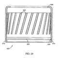
- the modified metal collar 300 is shown in particular in Figs. 26-29 , and is essentially simplified from the collar 124 of the first embodiment by providing a substantially cylindrical outer surface without annular ridges for mounting an overcap.
- This simpler configuration (with a longer straight cylindrical portion) provides a smooth aesthetic appearance to the entire collar 300 (which is not covered by an overcap), and also permits the internal ribs 320 to be longer as well (see Fig. 29 ).
- the friction between the ribs 320 and the ferrule 122 may be increased, as may the interference against axially pulling the fully mounted collar 300 off the ferrule 122, even though the ribs 320 extend up above the engaged outer surface of the ferrule 122 and therefore at their upper end are not enclosed by creep of the ferrule 122.
- this design may permit the collar 300 to be more readily twisted and pulled off if necessary for some unusual reason, such removal would still not be easy given the interference between the bottom of the ferrule skirt and the collar Nomar edge 310.
- the present invention permits easy and reliable assembly of a dispenser assembly 90, and further permits easy and reliable mounting of the assembly 90 on a container 100. Moreover, the present invention significantly reduces the likelihood that the dispenser assembly 90 will inadvertently or undesirably become decoupled from the container 100. In particular, the assembly 90 can be properly installed without requiring an excessive installation force - yet the installed configuration provides a greatly increased resistance to removal (owing significantly to the interference between the bottom of the ferrule corners 134 and the Nomar edge shoulders 224, 324 ( Figs. 20 and 35 )).
Description
- The present invention relates generally to dispensers or dispensing assemblies for receptacles containing fluid products to be dispensed, and the invention is especially suitable for use with bottles containing fragrance fluids or other personal care products.
- Generally speaking, prior art fragrance dispensers and other personal care product dispensers include a pump or aerosol module with a finger actuator for operating the module. Pump dispensers typically also include at least the following additional components: (1) a ferrule that contains the pump module and crimps onto or otherwise engages the receptacle (e.g., glass bottle, plastic container, or metal can), (2) a gasket that seals the ferrule to the top of the flange on the receptacle's neck (although some dispenser designs do not require a gasket if the ferrule material is soft enough to provide a good seal), and (3) a decorative collar around the ferrule. A cap may also be provided over the finger actuator and collar, either in a slip-fit or a snap-fit arrangement.
- Typically, a pump module held in a ferrule is retained on a glass bottle by one of two methods:
- (a) the lower edge of the ferrule, typically comprised of aluminum, is collapsed inwardly under the neck flange of the bottle by a crimping tool. Then, the collar is pushed over the ferrule as a separate operation; or
- (b) the ferrule, made of either plastic or metal, has one or more retention portions that are moved, or retained, under the neck flange of the bottle by sliding the collar down the ferrule. With some designs, the collar and ferrule are initially "preassembled" by the module manufacturer so that the collar is in an "up" shipping position on the upper end of the ferrule, and subsequently the assembly is shipped to the customer (e.g., a fluid product manufacturer) who mounts the assembly on the bottle flange, and then pushes the collar all the way down on the ferrule to move and/or retain the retention portions under the bottle flange.
- In either case, the collar can be metal or plastic. Usually, retention of a plastic collar on the ferrule is not a major concern because designs incorporate either snap fits or high force press fits (i.e., "heavy press fits") that do not compromise the outer aesthetics of the collar. However, metal collars are usually fabricated in aluminum and then anodized to produce a lustrous surface. In order to accommodate physical tolerances in the ferrule and collar diameters, the internal surface of the collar may contain multiple, elongated, vertical ribs that project radially inwardly several thousandths of an inch off the inner surface thereof. When the collar is pushed over the ferrule with a heavy press fit, the collar slightly deforms, distorts, or "breathes," into the shape of a polygon, with a resiliency that accommodates the tolerances. Another function of the ribs is to concentrate the "hoop" stress at multiple points, causing the ribs to dig into the ferrule and thus increase the resistance to removal.
- However, finding the optimal parameters that provide the best retention and sealing of the module to the receptacle is difficult and heretofore has been elusive. For example, although the press fit over the ferrule must be strong enough to assure that the collar cannot be accidentally pulled off the ferrule, the fit must not be so strong as to damage the outer surface of the collar. The outer surface of the collar is especially susceptible to damage because the anodized surface of the collar is typically a very thin film of aluminum oxide that contains a colorant dye. When stressed in tension, the oxide film can crack, creating a diffraction grating that produces a rainbow effect that detracts from the aesthetics. As a result, the rib locations become evident on the outer surface of the collar, a condition known as "crazing."
- Similarly, while the press fit force must be high enough to compress the gasket sufficiently to ensure sealing to the bottle neck so as to avoid leaking, the press fit force should not be so high as to over-compress the gasket, causing it to extrude out from under the ferrule, or create such stresses that the bottle collapses or breaks.
- Accordingly, it can be seen that improvements in the art are still desired. Specifically, it is desired to improve the state of the art collars to be able to increase the collar retention force (i.e., the force required to pull a collar off) while also not requiring so much force in initially applying the collar that crazing, bottle leaking, or breaking occurs.
- Another proposal that has been used is shown in
U.S. Patent No. 6,253,941 , which discloses a ferrule with a continuous skirt having an outwardly projecting lower edge which is deformed inwardly under the rim or flange of the container neck by the bottom portion of the rigid outer collar when the collar is forced down over the ferrule during the assembly process. However, it should be appreciated that the ferrule disclosed in that patent can therefore generally rest loosely on the container rim prior to the collar being pushed down over the ferrule during the assembly process. As a result, the ferrule may undesirably be dislodged or otherwise mis-positioned on the container rim during automated machine assembly. - Still another proposal which has been suggested is shown in
U.S. Patent No. 6,935,540 , which describes a collar having angled ribs which facilitate securing of the collar to a ferrule of a dispensing assembly. While the collar such as disclosed therein may be advantageously used with a variety of ferrules, such ferrules may be subjected to some of the same drawbacks as referenced above. - Another improvement that has been suggested is to provide spiraling ribs in the inner surface of the collar, such as described in
U.S. Pat. No. 5,799,810 . In that structure, the bottom of the ferrule skirt has circumferentially spaced legs or tabs with catches or feet so that the ferrule may be pushed down over the container rim for initial assembly whereby the tabs will flex out to allow the feet to pass the rim and then snap back in when the feet pass the rim, whereby the feet will grip under the rim. The collar is then pushed down over the ferrule so as to trap the tabs and prevent the tabs from being pulled, or flexing, back out--the lowered collar thereby securing the dispensing assembly on the container rim. The spiral ribs on the collar assist in securing the collar on the ferrule, while also permitting the collar to be subsequently twisted off of the ferrule in order to then permit the tabs to flex out as would be necessary to remove the assembly, such as may be desired for recycling the components of a used assembly. - In a typical method of assembling a dispensing package employing the types of collars and ferrules disclosed in the above-discussed
U.S. Patent No. 5,799,810 , the pump module is initially snap-fitted into the ferrule. If the ferrule is not itself capable of providing a seal (e.g., if the ferrule material is not soft enough to compress against and seal against the end of the bottle neck), a gasket is disposed inside the ferrule and around the module in a friction fit. Then the metal collar is mounted partially on the ferrule (i.e., the collar is pushed only partway down on the ferrule) in an "up" shipping position or configuration. The dispensing assembly is then shipped to the customer (e.g., a product manufacturer) for mounting to the bottle containing the fluid product. During such shipping and subsequent handling of the dispensing assembly, care must be exercised to avoid knocking the collar into a crooked orientation or off of the ferrule altogether. Thus, it would be desirable to provide an improved dispensing assembly facilitating initial mounting of the collar on the ferrule so that the collar can be initially positioned in the "up," shipping position with an increased retention force while also accommodating subsequent lowering of the collar completely over the ferrule. - Document
EP 0 707 895 A2 discloses the preamble of claim 1 and relates to a sleeve (1) for the fixing of a pump (2) to a bottle with a neck (3) enlarged at the mouthpiece (4). The upper part (1a) of the sleeve (1) has tubular elements: one external tubular element (10) for receiving a metallic covering (5) and an internal tubular element (11) for receiving and restraining the pump (2), and a base transversal element (12) resting on the mouthpiece (4), between said base transversal element (12) and mouthpiece (4) being interposed an annular gasket (6). The lower tubular part (1b) of the sleeve is to be inserted onto the mouthpiece (4) and is held in place in its undercut (4a) by means of rounded projecting parts (16) shown internally by the part (1b). Said lower tubular part (1b) is provided with a plurality of facings (15) which are obtained externally on said part (1b). The part (1b) has externally a plurality of step projections (20) between the facings (15). - Document
US 722,642 relates to an invention relating to protective closure for bottles and other containers, and is concerned more particularly with a protective closure having novel features which enable it to be readily applied to the top of a container, such as a bottle, and to be secured firmly in place without the use of spinning or similar machine operations. - It would be beneficial if an improved dispensing assembly for a dispensing package could optionally accommodate incorporation of various aesthetically pleasing designs.
- The improved dispensing assembly should preferably also accommodate designs for use with standard or conventional containers, especially glass bottles.
- It would also be desirable if the constituent components of such an improved assembly could be relatively easily and economically manufactured with high production quality, and could provide consistent operating parameters unit-to-unit with high reliability.
- The present invention is directed toward overcoming one or more of the problems set forth above, and provides an improved system which can accommodate designs having one or more the above-discussed benefits and features.
- The present invention provides components for securing a container of a fluent material product to a dispenser that may include a dispenser cartridge (e.g., a dispensing pump cartridge or an aerosol dispensing valve) having an upwardly projecting, reciprocatable, product-dispensing stem and an attached actuator (e.g., button) through which the product can be discharged.
- The present invention provides components for a dispensing assembly as set forth in claim 1 and a method for securing said components as set forth in
claim 14. Preferred embodiments are defined by the dependent claims. - Numerous other advantages and features of the present invention will become readily apparent from the following detailed description of the invention, from the claims, and from the accompanying drawings.
- In the accompanying drawings that form part of the specification, and in which like numerals are employed to designate like parts throughout the same,
-
Figure 1 is a fragmentary, isometric view of a hand-holdable dispensing package incorporating a glass bottle and a first embodiment of a finger-actuatable dispensing pump assembly, and the package is shown with the dispensing pump assembly in an unactuated condition prior to use and without the installation of a dust cap or overcap; -
Figure 2 is a view similar toFigure 1 , butFigure 2 shows the dust cap or overcap installed; -
Figure 3 is a fragmentary, exploded, isometric view of the package illustrated inFigure 2 ; -
Figure 4 is an isometric view of the ferrule of the dispensing pump assembly shown inFigure 3 from a vantage point generally above, or from the top of, the ferrule; -
Figure 5 is an elevational view of the side of the ferrule shown inFigure 4 as viewed directly toward one of eight corners of a lower portion of the ferrule; -
Figure 6 is a view similar toFigure 5 , butFigure 6 shows the ferrule rotated toward the left about 22.5 degrees; -
Figure 7 is a bottom view of the ferrule shown inFigure 4 ; -
Figure 8 is a top, plan view of the ferrule shown inFigure 4 ; -
Figure 9 is an enlarged, cross-sectional view taken generally along the plane 9-9 inFigure 8 (i.e., across two, diametrically opposite corners); -
Figure 10 is an enlarged, cross-sectional view taken generally along the plane 10-10 inFigure 8 (i.e., across two, diametrically opposite flat regions between the corners); -
Figure 11 is a side, elevational view of the metal collar employed in the first embodiment of the dispensing pump assembly shown inFigure 3 ; -
Figure 12 is a bottom view of the collar shown inFigure 11 ; -
Figure 13 is a top, plan view of the collar shown inFigure 11 ; -
Figure 14 is an enlarged, cross-sectional view taken generally along the plane 14-14 inFigure 13 ; -
Figure 15 is an enlarged, fragmentary, longitudinal, cross-sectional view of the first embodiment of the dispensing pump assembly components in an assembled shipping configuration prior to mounting on the bottle, except thatFigure 15 shows the internal dispensing pump cartridge and dip tube in a side, elevational view, andFigure 15 is viewed across two of the diametrically opposite corners of the ferrule corresponding to the cross-sectional view of the ferrule shown inFigure 9 ; -
Figure 16 is a fragmentary, greatly enlarged, cross-sectional view of a right-hand portion of the dispensing pump assembly shown inFigure 15 . -
Figure 17 is an enlarged, fragmentary, longitudinal, cross-sectional view of the first embodiment of the dispensing pump assembly components in an assembled shipping configuration prior to mounting on the bottle, except thatFigure 17 shows the internal dispensing pump cartridge and dip tube in a side, elevational view, andFigure 17 is viewed across two of the flat regions of the ferrule corresponding to the cross-sectional view of the ferrule shown inFigure 10 ; -
Figure 18 is a fragmentary, greatly enlarged, cross-sectional view of a right-hand portion of the dispensing pump assembly shown inFigure 17 ; -
Figure 19 is a view similar toFigure 15 , butFigure 19 shows the dispensing pump assembly mounted on the bottle shown inFigure 2 ; -
Figure 20 is a fragmentary, more greatly enlarged, cross-sectional view of a right-hand portion of the dispensing pump assembly and bottle shown inFigure 19 ; -
Figure 21 is a cross-sectional view taken generally along the plane 21-21 inFigure 19 ; -
Figure 22 is a fragmentary, cross-sectional view taken generally along the plane 22-22 inFigure 20 ; -
Figure 23 a view similar toFigure 17 , butFigure 23 shows the dispensing pump assembly mounted on the bottle shown inFigure 2 ; -
Figure 24 is a fragmentary, even more greatly enlarged, cross-sectional view of a right-hand portion of the dispensing pump assembly and bottle shown inFigure 23 ; -
Figure 25 is a fragmentary, isometric view of a hand-holdable dispensing package incorporating a glass bottle and a second embodiment of a finger-actuatable dispensing pump assembly, and the package is shown with the second embodiment of the dispensing pump assembly in an unactuated condition prior to use and without the installation of a dust cap or overcap; -
Figure 26 is a fragmentary, exploded, isometric view of the package illustrated inFigure 25 ; -
Figure 27 is a top, plan view of the collar shown inFigure 26 ; -
Figure 28 is a bottom view of the collar shown inFigure 26 ; -
Figure 29 is an enlarged, cross-sectional view taken generally along the plane 29-29 inFigure 28 ; -
Figure 30 is an enlarged, fragmentary, longitudinal, cross-sectional view of the second embodiment of the dispensing pump assembly components in an assembled shipping configuration prior to mounting on the bottle, except thatFigure 30 shows the internal dispensing pump cartridge and dip tube in a side, elevational view, andFigure 30 is viewed across two of the diametrically opposite corners of the ferrule corresponding to the cross-sectional view of the ferrule shown inFigure 9 ; -
Figure 31 is a fragmentary, greatly enlarged, cross-sectional view of a right-hand portion of the dispensing pump assembly shown inFigure 30 . -
Figure 32 is an enlarged, fragmentary, longitudinal, cross-sectional view of the second embodiment of the dispensing pump assembly components in an assembled shipping configuration prior to mounting on the bottle, except thatFigure 32 shows the internal dispensing pump cartridge and dip tube in a side, elevational view, andFigure 32 is viewed across two of the flat regions of the ferrule corresponding to the cross-sectional view of the ferrule shown inFigure 10 ; -
Figure 33 is a fragmentary, greatly enlarged, cross-sectional view of a right-hand portion of the dispensing pump assembly shown inFigure 32 ; -
Figure 34 is a view similar toFigure 30 , butFigure 34 shows the dispensing pump assembly mounted on the bottle shown inFigure 25 ; -
Figure 35 is a fragmentary, more greatly enlarged, cross-sectional view of a right-hand portion of the dispensing pump assembly and bottle shown inFigure 34 ; -
Figure 36 is a cross-sectional view taken generally along the plane 36-36 inFigure 34 ; -
Figure 37 is a fragmentary, cross-sectional view taken generally along the plane 37-37 inFigure 34 ; -
Figure 38 a view similar toFigure 32 , butFigure 38 shows the dispensing pump assembly mounted on the bottle shown inFigure 25 ; and -
Figure 39 is a fragmentary, even more greatly enlarged, cross-sectional view of a right-hand portion of the dispensing pump assembly and bottle shown inFigure 38 . - While this invention is susceptible of embodiment in many different forms, this specification and the accompanying drawings disclose only some specific forms as examples of the invention. The invention is not intended to be limited to the embodiments so described, however. The scope of the invention is pointed out in the appended claims.
- For ease of description, the components of this invention and the container employed with the components of this invention are described in the normal (upright) operating position, and terms such as upper, lower, horizontal, etc., are used with reference to this position. It will be understood, however, that the components embodying this invention may be manufactured, stored, transported, used and sold in an orientation other than the position described.
- Figures illustrating the components of this invention and the container show some conventional mechanical elements that are known and that will be recognized by one skilled in the art. The detailed descriptions of such elements are not necessary to an understanding of the invention, and accordingly, are herein presented only to the degree necessary to facilitate an understanding of the novel features of the present invention.
- The present invention provides an improved system for mounting a fluid dispensing module to a container. One presently preferred form of the invention is especially adapted for mounting a dispensing module in the form of a finger-operable, spray pump cartridge to a glass bottle that is particularly suitable for perfumes. However, the broad aspects of the invention are not limited to a particular dispensing module. Further, although the detailed design of the dispensing module forms no part of the broad aspects of the present invention, a brief discussion of some common types of dispensing modules is next presented below.
- Finger-operable dispensing modules or dispensers (which can include, for example, both dispensing pumps and aerosol dispensing valves) are typically adapted to be mounted on hand-held containers that are commonly used for liquid products. Typically, some pumps and valves operate with a suitable discharge structure, such as a mechanical break-up unit, to produce a fine mist or atomized spray of the liquid product (e.g., perfume). Some pumps also operate to dispense a quantity of product in a liquid, cream, or paste form.
- Some finger-operable pumps conventionally employ a dispensing module in the form of a pump cartridge having a chamber in which is disposed a pressurizing piston that can be actuated by the user's finger pressing down on an external actuator (e.g., button) which has a dispensing passage and which is connected to the piston with a hollow discharge tube or stem (which may typically be molded as a unitary part, or extensions of, the piston). The hollow stem establishes communication between the pump chamber and actuator from which the product is discharged. A spring acts against the piston or actuator to return the piston and actuator upwardly to the elevated, rest position when the finger pressing force is released.
- Like the above-discussed pump type dispensers, aerosol valve dispensers are typically mounted at the top of a container, such as a metal can containing a pressurized product. Conventional aerosol valve dispensing systems for a container have a dispensing module that includes a hollow body which is open at the top and bottom ends and which is mounted in the top of the container. The bottom end of the hollow body is open to the pressurized contents in the container (usually through a dip tube connected to the bottom end opening in the aerosol valve body). A compression spring in the body biases a stem upwardly to project partly out of a body top end opening through an annular gasket at the top of the body. The upper part of the stem includes an internal, vertical discharge hole that is open at the upper end of the stem and that is connected to an external actuator button which has a dispensing passage from which the aerosol spray can be dispensed. Below the upper end of the stem, the stem has one or more lateral orifices which communicate with the vertical discharge hole inside the stem. Until the actuator button is pressed, the lateral orifices in the stem are located adjacent the inner cylindrical vertical surface of the annular gasket at the top of the valve body, and fluid inside the valve body is blocked by the gasket from flowing into the stem lateral orifices. When the actuator button is depressed, the stem is forced downwardly against the spring so as to locate the lateral orifices in the body below the gasket to permit the pressurized fluid in the valve body to flow through the stem lateral orifices, up the stem vertical hole, and through the actuator button.
- Reference will now be had to the Figures and preferred embodiments incorporating the present invention providing an improved system for mounting a fluid dispensing module to a container. Some presently preferred forms of the present invention are described hereinafter as incorporated in a dispensing assembly that employs a dispensing module in the form of a finger-operable spray pump cartridge mounted on a glass bottle.
-
Figs. 1-3 illustrate a first embodiment of the present invention which consists of a dispensingassembly 90 for mounting to a container orreceptacle 100. The illustratedreceptacle 100 is shown in one preferred form as a conventional, transparent, glass bottle suitable for containing a liquid perfume. As best illustrated in the exploded view ofFig. 3 , thecontainer 100 includes aneck 102 with an outwardly projecting rim, lip orflange 104 at its upper end. The top of thebottle flange 104 has an upwardly projecting, annular sealing bead 105 (seeFigs. 3 and19 ). - A
suitable dispensing module 106, such as previously discussed, includes apump cartridge 108, adip tube 110, and an upwardlybiased stem 112 on which anexternal actuator button 114 is disposed. (Thedip tube 110 is illustrated inFigs. 1 and2 as visible as would be the case with a transparent or translucent container 100). It will be appreciated by those skilled in the art that a user may press down on thebutton 114 in order to operate thepump cartridge 108 whereby fluid in thecontainer 100 is pumped up through thedip tube 110 and stem 112 and dispensed as a fine mist spray out the opening in theactuator button 114. - In one preferred form, a gasket 120 (preferably molded from a plastic rubber),
ferrule 122 andcollar 124 function to secure the assembly to thecontainer 100 as described in greater detail below. A removable dust cap or overcap 126 (seeFigs. 2 and3 ) is also provided for decorative design as well as to protect theactuator button 114 and prevent inadvertent dispensing of the product. - The
ferrule 122 of the first embodiment is illustrated in detail inFigs. 4-10 , and may be advantageously molded of a durable but somewhat resilient, plastic material (e.g., polypropylene). - The
ferrule 122 includes alower skirt 130 having an outer surface which is generally a regular polygon in cross-section, and in the illustrated embodiment is generally octagonal with eight generallyflat surfaces 132 connected at eight outwardly projecting, somewhat cut-off corners 134 (see, e.g.,Figs. 7 and8 ). Theskirt 130 may advantageously be continuous, although it should be appreciated that aferrule 122 in which theskirt 130 is slit, particularly in theflat surfaces 132, could also be used with the present invention. - As best illustrated in
Fig. 9 , the outer surface of theskirt 130 at each of thecorners 134 has, at the upper end, alip 136 having an outer diameter ODC1 with recessedarea 138 beneath thelip 136. A generally flat and axially extendingsurface 140 extends below the recessed area 138 (where the outer diameters at the top and bottom are the same: ODC2 = ODC3). Thebottom portion 142 of theskirt corners 134 are tapered outwardly at an angle A (seeFig. 9 ) whereby the outer diameter at the bottom ODC4 is slightly greater than the outer diameter ODC3 of theaxially extending surface 140 thereabove. As illustrated inFig. 10 , theflat surfaces 132 of theferrule 122 between thecorners 134 may be slightly tapered inwardly from top to bottom (e.g., by the angle B as illustrated inFig. 10 , where the outer diameter at the top of the skirt ODF1 is greater than the outer diameter at the bottom of the skirt ODF2 owing to the taper angle B). - The
inner surface 150 of theskirt 130 is, by contrast, generally cylindrical (seeFig. 7 ) with elongated ribs ornibs 152 projecting inwardly therefrom. Specifically, as best seen inFigs. 7 ,9 and10 , sets of threenibs 152 are provided at eachcorner 134, where eachnib 152 includes alower face 156 which tapers in toward the axial center of theferrule 122 from the bottom at a point spaced above the bottom of theskirt 130, and includes a less taperedupper shoulder 158. - The internal diameter of the ferrule122, the distance each
nib 152 projects inwardly, and the heights of the nib surfaces 156 and 158 are determined by the size and type ofbottle flange 104 on which theferrule 122 is to be mounted. For example, in the perfume pump spray bottle industry, different bottle flange sizes are provided according to industry standards such as GPI and FEA. - The exterior configuration and size of the
ferrule 122 can be constant regardless of the interior size and configuration of theferrule 122. Thus, the design of the exterior of theferrule 122 and the design of thecollar 124 can remain the same regardless of the type and size of the bottle on which the dispensing assembly is to be installed. - The
ferrule 122 includes a deck or downwardly facingshoulder 160 extending inwardly from the upper end of theskirt 130, which shoulder 160 is adapted for seating against thegasket 120 on the top of the container neck 102 (seeFigs. 3 and19 ) when assembled as further described below. - In many instances, the hardness of the material of the
ferrule 122 desired to ensure that theferrule 122 will be properly retained on thecontainer neck 102 as described in detail herein will be such that asofter gasket 120 may be advantageously used as described and shown to ensure a proper seal: However, if theferrule deck 160 is capable of forming an adequate seal on top of thecontainer neck 102, thegasket 120 may be omitted. Therefore, it should be recognized that it would be within the scope of the present invention to provide aferrule 122 which itself has sufficient softness to provide a desired seal without inclusion of a separate gasket. - A generally cylindrical turret or cap portion 170 (
Fig. 10 ) with acentral opening 172 extends up from theferrule shoulder 160 and includes a reduceddiameter portion 174 on its inner surface. It should be appreciated that thepump cartridge 108 may be secured in thecap portion 170 with the flange 176 (seeFigs. 3 and19 ) of thecartridge 108 trapped above the reduceddiameter portion 174 with thestem 112 extending through thecentral opening 172. A concentricouter lip 178 also extends up from theshoulder 160 and surrounds thecap portion 170 to define anannular space 180 therebetween, and a lower skirt on theactuator button 114 may be guided within thespace 180, and protected, during reciprocating pumping movement of the actuator button 114 (seeFig. 19 ). - An outer shoulder or
lip 184 defining outwardly extending lips at the corners above theferrule skirt 130 is also provided to facilitate assembly as described hereinafter. - A notch 188 (
Fig. 4 ) may also be provided in the upper end of theouter lip 178 to accommodate the mold gate for the injection of the thermoplastic resin during molding of theferrule 122. - The
metal collar 124 of the embodiment ofFigs. 1-3 is illustrated inFigs. 11-14 wherein, as best seen inFig. 14 , the collar consists of two parts: aninner mounting collar 200 and an outerdecorative collar 202 which is secured thereon. Bothcollars collar 124 may in one form be a single annular metal piece, and in another form may be a subassembly, such as illustrated, of two separate pieces (200, 202) which are mechanically staked together to form a single, integral subassembly for mounting on theferrule 122 in a process described in detail hereafter. - As can be seen in
Fig. 14 , the mountingcollar 200 is generally cylindrical with an inwardly extendinglip 206 at its upper end and aNomar edge 210 at its lower end. A pair of spacedannular ridges collar 200 above thedecorative collar 202 to define a groove within which the cap 126 (seeFigs. 2 and3 ) may be snapped in order to be secured thereon (seeFig. 15 ). Also provided around the lower portion of the mountingcollar 200 are a plurality ofdiscrete ribs 220 which project inwardly from the inner surface of thecollar 200 and extend generally axially but at an angle of, for example, about 15° (± 5°) from the axial direction. - As indicated in
Fig. 14 , the inner diameter of the mountingcollar 200 between theannular ridges collar 200 is ID3, with theribs 220 projecting inwardly to an effective inner diameter (between two diametrically opposite ribs) of ID2. As will be understood by those skilled in the art, theNomar edge 210 at the lower end of the mountingcollar 200 consists of a thinned annular portion above a thickened bottom annular portion (formed by bending up the bottom edge of the thinner, lower portion of the collar). Above the thickened bottom annular portion on the inside of thecollar 200 there is a recess which, accordingly, has an increased inner diameter so that the thickened bottom annular portion has a smaller inner diameter ID4 so as to define an upwardly facingshoulder 224 that presents an annular face facing toward the top end of thecollar 200. - Reference will now be had to
Figs. 15-18 , in which the above described components are illustrated as assembled but prior to mounting on acontainer 100. In this condition, it should be appreciated that the components are in substantially the same relative orientation to one another that they will be when finally assembled on acontainer 100 except that the mountingcollar 200 is snap fit in a raised position relative to theferrule 122. In this raised (shipping) position, thecollar 124 is only partially pushed onto theferrule 122 with the bottom (Nomar) edge, at thecorners 134, secured to theferrule 122 between thelip 136 and the outer lip 184 (seeFig. 9 ) as seen inFigs. 15 and16 . At theflat surfaces 132 between thecorners 134, the lower end of the mountingcollar 200 may be spaced from the outer surface of theferrule 122 as shown inFigs. 17 and18 . (Thegasket 120 may be stretched to fit over thepump cartridge 108 whereby it is frictionally held thereon as illustrated.) These Figures illustrate a shipping position in which the components are secured together in an assembled condition and can be handled by a customer to securely mount the assembly to the customer's filledcontainer 100 as further described hereafter. - Mounting of the dispensing
assembly 90 to acontainer 100 will now be described, such mounting being illustrated inFigs. 19-24 . - Specifically, advantageously according to the present invention, the
ferrule 122 is pushed down over thebottle neck 102 during initial assembly, at which time thenibs 152 are first forced outwardly (by compression of thenibs 152 and stretching of the skirt 130) in order to pass over thebottle flange 104 at the upper end of thebottle neck 102. While the size of thebottle flange 104 may vary fordifferent bottles 100 and may also vary due to manufacturing tolerances, the compression of thegasket 120, and the elasticity of theferrule skirt 130 andnibs 152 cause thenibs 152 to move radially inwardly under thebottle flange 104 at the end of the initial phase of the mounting process. This occurs generally when the lower faces 156 of thenibs 152 pass below thebottle flange 104, at which point theupper shoulder 158 of thenibs 152 will either move under thebottle flange 104 or move under by compressing somewhat to provide some gripping or holding force preventing theferrule 122 from being removed from thebottle neck 102. - The mounting process may be effected entirely by automated equipment or partly manually. In either case, the process begins with the assembled components (as in
Figs. 15-18 ) provided to a bottler (typically, however, without thecap 126 thereon during mounting). If a partially manual process is employed to mount the dispensingassembly 90 on thecontainer 100, then the ferrule 122 (withgasket 120, dispensingmodule 106; and initially positioned collar 124) are manually pushed onto the neck of a filled container 100 (such as a bottle) at a first work station. During this step, thecollar 124 does not move relative to theferrule 122 so that thecollar 124 remains in the "up" position between theferrule lips Fig. 15 . Theferrule 122 andcollar 124 thus move downwardly together on thebottle flange 104. The snap-fit engagement of theferrule 122 with thebottle neck flange 104 maintains theassembly 90 in position on thebottle 100 while thebottle 100 is moved to a second work station at which a mechanical plunger device is operated to hold thebottle 100 and push themetal collar 124 all the way down on theferrule 122. Because the outside diameters of portions of theferrule 122 are greater than some inner diameters of portions of thecollar 124 as described above, portions of theferrule 122 are compressed and deformed inwardly (and, to a small extent, thecollar 124 may stretch radially outwardly) as a tight, interference fit is established. - In a fully automatic mounting process, the assembly of the
gasket 120, dispensingmodule 106,ferrule 122, andcollar 124 may be pushed down on thebottle 100 in one continuous motion by a spindle. The spindle exerts an initial force (e.g., 30 to 40 pounds) on the top of thecollar 124 so that thecollar 124 andferrule 122 move together until the bottom of theferrule 122 initially snaps down over thebottle flange 104 and can be pushed down no further as previously described. The spindle then exerts a greater force (e.g., 40 to 80 pounds) in the final phase of mounting so that thecollar 124 is then moved all the way down relative to theferrule 122 so as to completely surround the exterior side of theferrule 122 as shown inFigs. 19-24 and further described below. - Specifically, when the
collar 124 is pushed over theferrule 122 during the final phase of the mounting on abottle neck 102, the bottom of theNomar edge 210 of thecollar 124 initially pushes down on thelip 136 at thecorners 134 of theskirt 130, distorting thelip 136 and pushing its material down around the outside of the skirt. The recessedarea 138 beneath thelip 136 provides a space into which the lip material can be deformed so that, once a sufficient force is applied to thecollar 124 during mounting to distort thelip 136 and begin moving thecollar 124 down over theferrule 122 as desired, the deformed material of thelip 136 will thereafter provide little hindrance to thecollar 124 as thecollar 124 continues to be pushed over theferrule 122. As a result, thecollar 124 can be pushed down with a sufficient, but not excessive, vertical installation force (e.g., less than 100 pounds, such as 80 pounds in one proposed commercial design) which will not risk damaging thecollar 124 orcontainer 100 in the process. - As the
collar 124 continues to be pushed down over theferrule 122 during the final mounting phase, it squeezes the outer surface of theferrule 122 inwardly against the radial outward surface of thebottle flange 104. While this will involve some squeezing inwardly of thenibs 152 to a position which is further under thebottle flange 104 compared to the initial phase of the mounting, thenibs 152 are already generally under thebottle flange 104 after the initial mounting phase as previously described. - In the fully mounted configuration as shown in
Figs. 19-24 , thecollar 124 has been pushed all the way down over theferrule 122 so that theNomar edge 210 is beneath the bottom edge of theferrule skirt 130, with the skirt elastically expanded outwardly so that it is above the upwardly facingshoulder 224 of theNomar edge 210. In this position, thenibs 152 are secured by the surrounding substantiallyrigid collar 124 underneath thebottle flange 104 whereby the mounted dispensingassembly 90 is securely retained on thebottle neck 102. While some buckling of theflat surfaces 132 of theferrule skirt 130 may result in portions of theskirt 130 being positioned below thebottle flange 104, it is thenibs 152 which substantially retain theassembly 90 on thebottle neck 102. - Further, in addition to the interference between the
Nomar edge shoulder 224 and the bottom of the ferrule 122 (particularly at the skirt corners where thebottom portions 142 are tapered outwardly) which secures thecollar 124 from being slid back up off theferrule 122 after mounting, it should be appreciated that theribs 220 on the inner surface of thecollar 124 will also secure thecollar 124 on theferrule 122, as theribs 220 press into the outer surface of the ferrule skirt 130 (at least at the corners 134), providing not only a friction connection but also, due to their slight angle relative to the axial direction, an interference against thecollar 124 being pulled axially off theferrule 122. Moreover, such angled orientation of theribs 220 enables theribs 220 to be slid down relatively easily (and possibly slightly "screwed on") during the final phase of the mounting process without requiring that an undesirably excessive mounting force be applied to thecollar 124. Once fully mounted, cold flow or creep of the plastic material of theferrule 122 around theribs 220 will further facilitate long term holding of thecollar 124 on theferrule 122. - By way of example, the following previously discussed dimensions have been found to be suitable for a
ferrule 122 andcollar 124 combination such as described above for mounting on a conventional glass bottle 100 (e.g., FEA design) having aflange 104 with a nominal outside diameter which is (a) greater than an effective inner diameter between two diametricallyopposite ferrule nibs 152 of 14.70 mm ± 0.20 and (b) no greater than an inside diameter of theferrule skirt 150 of 15.60 mm ± 0.13, for example, abottle neck 104 having a nominal outside diameter of 15 mm: -
Fig. 9 (ferrule 122 at corners 134):- Angle A = 20° (18° to 25°)
- ODC1 = 16.73 mm ± 0.08
- ODC2 = 16.60 mm ± 0.10
- ODC3 = 16.60 mm ± 0.10
- ODC4 = 17.10 mm ± 0.10
-
Fig. 10 (ferrule 122 at flat surfaces 132):- Angle B = 1° Reference
- ODF1 = 16.18 mm ± 0.15
- ODF2 = 15.95 mm ± 0.15
-
Fig. 14 (collar 124):- ID1: = 16.08 mm
- ID2 = 16.08 mm ± 0.03
- ID3 = 16.33 mm ± 0.03
- ID4 = 16.13 mm
-
Figs. 25-39 illustrate an alternate embodiment of adispensing module 90A also incorporating aspects of the present invention. In this embodiment, the components may be the same as in the first described embodiment except that adifferent collar 300 is used, without an overcap. Accordingly, the same reference numerals are used in theFigs. 25-39 as used to describe the same components inFigs. 1-24 and repetition of the details of those same components will not be made here. With respect to thedifferent collar 300, comparable elements will be identified by comparable reference numbers as used inFigs. 1-24 but with 100 added (e.g., theribs 220 inFig. 14 are identified asribs 320 where appropriate inFigs. 25-39 ). - Specifically, the modified
metal collar 300 is shown in particular inFigs. 26-29 , and is essentially simplified from thecollar 124 of the first embodiment by providing a substantially cylindrical outer surface without annular ridges for mounting an overcap. This simpler configuration (with a longer straight cylindrical portion) provides a smooth aesthetic appearance to the entire collar 300 (which is not covered by an overcap), and also permits theinternal ribs 320 to be longer as well (seeFig. 29 ). As a result, the friction between theribs 320 and theferrule 122 may be increased, as may the interference against axially pulling the fully mountedcollar 300 off theferrule 122, even though theribs 320 extend up above the engaged outer surface of theferrule 122 and therefore at their upper end are not enclosed by creep of theferrule 122. Moreover, while this design may permit thecollar 300 to be more readily twisted and pulled off if necessary for some unusual reason, such removal would still not be easy given the interference between the bottom of the ferrule skirt and thecollar Nomar edge 310. Further, given the slight angle of theribs 320, while this configuration would facilitate appropriate removal if necessary by a manufacturer with knowledge of the rib configuration, it would be unlikely to be accomplished by an individual who would be unlikely to apply the correct combined degrees of pulling and twisting which would be required to accomplish such removal. - Accordingly, should be appreciated that the present invention permits easy and reliable assembly of a
dispenser assembly 90, and further permits easy and reliable mounting of theassembly 90 on acontainer 100. Moreover, the present invention significantly reduces the likelihood that thedispenser assembly 90 will inadvertently or undesirably become decoupled from thecontainer 100. In particular, theassembly 90 can be properly installed without requiring an excessive installation force - yet the installed configuration provides a greatly increased resistance to removal (owing significantly to the interference between the bottom of theferrule corners 134 and the Nomar edge shoulders 224, 324 (Figs. 20 and35 )). - Still other aspects, objects, and advantages of the present invention can be obtained from a study of the specification, the drawings, and the appended claims. It should be understood, however, that the present invention could be used in alternate forms where less than all of the objects and advantages of the present invention and preferred embodiment as described above would be obtained within the scope of the appended claims.
Claims (15)
- Components for a dispensing assembly (90) for dispensing a substance from a receptacle (100), the receptacle (100) comprising a neck (102) and a flange (104), the dispensing assembly components comprising:- a ferrule (122) adapted to maintain a coupling of a dispensing module (106) to the receptacle (100), the ferrule (122) including- a shoulder member (160) securable to said dispensing module (106),- a skirt (130) which is generally annular about an axis and defines an axial aperture open on one end, wherein said dispensing module (106) extends through said aperture when secured to said shoulder member (160), and- nibs (152) extending from the inner surface (150) of said skirt (130) toward said axis,
wherein said skirt (130) and nibs (152) are plastic;- a substantially rigid annular collar (124) having a generally annular inner surface adapted to be positioned over said ferrule skirt outer surface when said ferrule (122) is mounted on said receptacle (100), said collar (124) being open on one end and having an inwardly extending annular flange (206) on the other end, and said collar inner surface including an annular recess adjacent said open end defining an annular face (224) facing said collar other end; wherein- said open one end of said ferrule skirt (130) extends radially outwardly into said annular recess of said collar inner surface when said dispensing assembly (90) is secured to the receptacle (100),- said skirt (130) is continuous, and- wherein said skirt (130) has an outer surface which, in a plane perpendicular to said axis, is substantially shaped as a regular polygon with flat surfaces (132) between corners (134),characterised in that- said annular recess is conically tapered outwardly toward said collar open end, and said components further comprising at least portions of said ferrule skirt outer surface tapered conically outwardly, wherein said ferrule skirt outer surface portions extend into said collar annular recess when said dispensing assembly (90) is secured to the receptacle (100). - The dispensing assembly components of claim 1, further comprising a dispensing module (106) secured to said ferrule (122).
- The dispensing assembly components of claim 1, wherein said collar (124) has a Nomar edge (210) that is located at said open end and defines said recess and said annular face (224).
- The dispensing assembly components of claim 1, further comprising elongated ribs (220) projecting inwardly from said collar inner surface.
- The dispensing assembly components of claim 4, wherein said ribs (220) are angled along the inner surface of the collar (124).
- The dispensing assembly components of claim 5, wherein each rib (220) forms an angle of approximately 5 to 15 degrees on the inner surface of the collar (124) relative to the axis.
- The dispensing assembly components of claim 1, wherein said corners (134) of said female skirt (130) are rounded.
- The dispensing assembly components of claim 1, wherein said corners (134) of said ferrule skirt outer surface extend into said collar annular recess when said dispensing assembly (90) is secured to the receptacle (100).
- The dispensing assembly components of claim 1, wherein the radius of said ferrule corners (134) from said axis is X, and the radius of said collar inner surface is Z, wherein X > Z prior to assembly of said collar (124) on said ferrule (122).
- The dispensing assembly components of claim 9, wherein the radius at the center of said ferrule flat surfaces from said axis is Y, wherein Y < Z.
- The dispensing assembly components of claim 1, wherein the radius at the center of said flat surfaces (132) from said axis is Y, and the radius of said collar inner surface is Z, wherein Y < Z.
- The dispending assembly components of claim 1, wherein the collar is made of aluminium.
- The dispensing assembly components of claim 1, further comprising a lip (136) on the ferrule outer surface adjacent said other end of said ferrule skirt (130) and a recess (138) beneath said lip (136), wherein said lip (136) extends to a diameter greater than the diameter of said collar one end.
- A method of securing the dispensing assembly components of claim 1 to a receptacle (100) comprising a neck (102) and a flange (104), characterised by the step of:locating the ferrule (122) on the receptacle flange (104) with said dispensing module (90) extending into said receptacle (100);pushing the ferrule (122) over the receptacle flange (104) to locate said ferrule nibs (152) beneath said receptacle flange (104); andpushing said collar (124) over said ferrule skirt (130) to trap said nibs (152) beneath said flange.
- The method of claim 14, further comprising providing a lip (136) on the ferrule (122) with a recess (138) beneath said lip (136), wherein:said locating step includes supporting said collar (124) on said ferrule lip (136);said ferrule pushing step includes pushing said collar (124) while said collar (124) is located on said ferrule lip (136) to move both said collar (124) and said ferrule (122) relative to said receptacle flange (104); andsaid collar pushing step includes pushing said collar (124) relative to said ferrule (122) to push the material of said ferrule lip (136) into said recess (138) beneath said lip (136).
Priority Applications (1)
| Application Number | Priority Date | Filing Date | Title |
|---|---|---|---|
| EP12176560.6A EP2514532B1 (en) | 2006-09-06 | 2007-09-04 | Dispenser assembly for a fluid dispensing receptacle and method of assembling same |
Applications Claiming Priority (1)
| Application Number | Priority Date | Filing Date | Title |
|---|---|---|---|
| US11/516,276 US7757902B2 (en) | 2006-09-06 | 2006-09-06 | Dispenser assembly for a fluid dispensing receptacle and method of assembling same |
Related Child Applications (2)
| Application Number | Title | Priority Date | Filing Date |
|---|---|---|---|
| EP12176560.6A Division EP2514532B1 (en) | 2006-09-06 | 2007-09-04 | Dispenser assembly for a fluid dispensing receptacle and method of assembling same |
| EP12176560.6 Division-Into | 2012-07-16 |
Publications (3)
| Publication Number | Publication Date |
|---|---|
| EP1897623A2 EP1897623A2 (en) | 2008-03-12 |
| EP1897623A3 EP1897623A3 (en) | 2009-07-08 |
| EP1897623B1 true EP1897623B1 (en) | 2012-11-07 |
Family
ID=38663575
Family Applications (2)
| Application Number | Title | Priority Date | Filing Date |
|---|---|---|---|
| EP07017311A Active EP1897623B1 (en) | 2006-09-06 | 2007-09-04 | Dispenser assembly for a fluid dispensing receptacle and method of assembling same |
| EP12176560.6A Active EP2514532B1 (en) | 2006-09-06 | 2007-09-04 | Dispenser assembly for a fluid dispensing receptacle and method of assembling same |
Family Applications After (1)
| Application Number | Title | Priority Date | Filing Date |
|---|---|---|---|
| EP12176560.6A Active EP2514532B1 (en) | 2006-09-06 | 2007-09-04 | Dispenser assembly for a fluid dispensing receptacle and method of assembling same |
Country Status (3)
| Country | Link |
|---|---|
| US (2) | US7757902B2 (en) |
| EP (2) | EP1897623B1 (en) |
| ES (2) | ES2519840T3 (en) |
Families Citing this family (24)
| Publication number | Priority date | Publication date | Assignee | Title |
|---|---|---|---|---|
| FR2891533B1 (en) * | 2005-10-04 | 2007-12-07 | Valois Sas | RECOVERY BODY, METHOD FOR MANUFACTURING SAME, AND FLUID PRODUCT DISPENSER USING SAME |
| FR2891530B1 (en) | 2005-10-04 | 2007-12-07 | Valois Sas | RECOVERY BODY, METHOD FOR MANUFACTURING SAME, AND FLUID PRODUCT DISPENSER USING SAME |
| FR2891529B1 (en) * | 2005-10-04 | 2007-12-07 | Valois Sas | RECOVERY ORGAN, PROCESS FOR PRODUCING SUCH ORGAN AND DISPENSER COMPRISING SUCH AN ORGAN |
| US20090014679A1 (en) * | 2007-07-13 | 2009-01-15 | Precision Valve Corporation | Plastic aerosol valve and method of assembly, mounting and retention |
| USD636668S1 (en) * | 2008-03-24 | 2011-04-26 | Mary Kay Inc. | Dip tubes |
| US20110108579A1 (en) * | 2008-05-19 | 2011-05-12 | Meadwestvaco Corporation | Pump retention collar and methods for using the same |
| FR2948344B1 (en) * | 2009-07-27 | 2011-09-02 | Valois Sas | DETACHABLE FASTENING SYSTEM. |
| US8939327B2 (en) * | 2010-03-18 | 2015-01-27 | Meadwestvaco Calmar, Inc. | Pump and bottle fitments and methods for using the same |
| FR2957900B1 (en) * | 2010-03-25 | 2012-05-11 | Rexam Dispensing Sys | SYSTEM FOR FIXING AN ORGAN FOR DISPENSING A FLUID PRODUCT ON A BOTTLE BED |
| FR2961192B1 (en) * | 2010-06-10 | 2012-07-27 | Rexam Healthcare La Verpillier | PRODUCT DISPENSING DEVICE COMPRISING A PUMP AND A DISTRIBUTION TIP |
| US11814239B2 (en) | 2011-05-16 | 2023-11-14 | The Procter & Gamble Company | Heating of products in an aerosol dispenser and aerosol dispenser containing such heated products |
| US9296550B2 (en) | 2013-10-23 | 2016-03-29 | The Procter & Gamble Company | Recyclable plastic aerosol dispenser |
| FR2975675B1 (en) * | 2011-05-23 | 2014-06-06 | Valois Sas | FIXING MEMBER AND DISPENSER COMPRISING SUCH AN ORGAN. |
| US20140263479A1 (en) * | 2013-03-14 | 2014-09-18 | Inoac Packaging Group, Inc. | Cap for a container |
| JP6651449B2 (en) * | 2013-08-26 | 2020-02-19 | ネルソン スタッド ウェルディング,インコーポレイテッド | Ferrule for welding stud to workpiece |
| USD794450S1 (en) * | 2014-06-19 | 2017-08-15 | Aptar France Sas | Dispenser |
| MX2017015112A (en) | 2015-05-27 | 2018-05-17 | Flow Control LLC | Cartridge pump. |
| US20170095757A1 (en) | 2015-05-27 | 2017-04-06 | Flow Control LLC | Cartridge Accumulator |
| WO2017048802A1 (en) | 2015-09-14 | 2017-03-23 | Flow Control Llc. | Cartridge accumulator |
| US10526133B2 (en) | 2017-02-28 | 2020-01-07 | The Procter & Gamble Company | Aerosol dispenser having a safety valve |
| WO2020041792A1 (en) | 2018-08-24 | 2020-02-27 | Clayton Corporation | Plastic mounting cup and valve for pressurized container |
| EP3969896A1 (en) * | 2019-05-15 | 2022-03-23 | Waters Technologies Corporation | Method and apparatus for high pressure sealing |
| US11407000B2 (en) | 2019-09-23 | 2022-08-09 | S. C. Johnson & Son, Inc. | Volatile material dispenser |
| FR3110150B1 (en) * | 2020-05-15 | 2022-06-10 | Pm France Packaging | Pump casing |
Family Cites Families (26)
| Publication number | Priority date | Publication date | Assignee | Title |
|---|---|---|---|---|
| US722642A (en) | 1902-01-17 | 1903-03-10 | Joshua W Sykes | Carpet-sweeper. |
| GB722642A (en) | 1952-10-24 | 1955-01-26 | Inter Seal Corp | Improvements in bottle closures |
| US2723773A (en) * | 1952-10-24 | 1955-11-15 | Interseal Corp | Bottle closures |
| US3112048A (en) * | 1961-06-08 | 1963-11-26 | Virjune Mfg Co Inc | Decorative ring and flexible insert for spray container |
| NO132792C (en) * | 1973-09-07 | 1976-01-07 | Nordpremium As | |
| US4073398A (en) * | 1977-01-28 | 1978-02-14 | The Risdon Manufacturing Company | Snap-lock device for securing a dispensing mechanism to a container |
| DE2813940A1 (en) * | 1977-04-23 | 1978-10-26 | Zensho Honma | BOTTLE CAP |
| US4251003A (en) * | 1979-01-19 | 1981-02-17 | Toni Casutt | Bottle closing device |
| US4284211A (en) * | 1979-09-26 | 1981-08-18 | Emson Research, Inc. | Nibbed ferrule for holding cap |
| CH643201A5 (en) * | 1979-11-07 | 1984-05-30 | Createchnic Patent Ag | SEALING CAP AND METHOD FOR THEIR PRODUCTION. |
| US4773553A (en) * | 1985-09-12 | 1988-09-27 | Risdon Corporation | Assembly for securing and sealing a dispenser to a flanged container |
| FR2651837B1 (en) * | 1989-09-08 | 1993-04-23 | Aerosol Inventions Dev | PRE-ORIENTABLE MANUAL PUMP ON THE CONE OF A CONTAINER. |
| US5192006A (en) * | 1991-05-01 | 1993-03-09 | Risdon Corporation | Low profile pump |
| US5348174A (en) * | 1993-01-14 | 1994-09-20 | Eyelematic Manufacturing Co., Inc. | Metal flexible finger ferrule for flanged container closure |
| US5299703A (en) * | 1993-06-30 | 1994-04-05 | American Dispensing Systems Inc. | Device for securing a dispenser to a glass container |
| DE4342680A1 (en) * | 1993-12-15 | 1995-06-22 | Pfeiffer Erich Gmbh & Co Kg | Discharge device for media |
| US5562219A (en) * | 1994-09-22 | 1996-10-08 | Valois, S.A. | Device for attaching a dispenser member to a receptacle |
| ATE174537T1 (en) | 1994-10-17 | 1999-01-15 | Sar Spa | SLEEVE FOR FASTENING A HAND-OPERATED PUMP UNIT TO A GLASS BOTTLE |
| FR2760725B1 (en) * | 1997-03-14 | 1999-05-28 | Teleplastics Ind | DISPENSING DEVICE FOR FLUID PRODUCTS |
| FR2769860B1 (en) * | 1997-10-16 | 2000-01-21 | Sofab | DEVICE FOR ASSEMBLING A PUMP ON A CONTAINER |
| IT1302351B1 (en) * | 1998-10-01 | 2000-09-05 | Cml Costr Mecc Liri Srl | STRETCHING MACHINE FOR ELONGATED PIECES WITH A POLYGONAL SECTION. |
| US6253941B1 (en) * | 1999-01-19 | 2001-07-03 | Crown Cork & Seal Technologies Corporation | Assembly for securing and sealing a dispenser to a flanged container |
| AU3292400A (en) * | 1999-03-23 | 2000-10-09 | Calmar-Monturas, S.A. | Bottle closing device |
| FR2820123B1 (en) * | 2001-01-30 | 2003-05-02 | Valois Sa | DEVICE FOR FIXING A DISPENSING MEMBER ON A CONTAINER NECK |
| ES2187341B1 (en) * | 2001-02-28 | 2004-08-16 | Saint-Gobain Calmar S.A. | CAPSULE OF A DEVICE FOR THE CLOSURE OF A BOTTLE. |
| US6776311B2 (en) * | 2002-11-13 | 2004-08-17 | Emsar, Incorporated | Dispenser assembly for a fragrance or personal care bottle and a method of assembling same |
-
2006
- 2006-09-06 US US11/516,276 patent/US7757902B2/en not_active Expired - Fee Related
-
2007
- 2007-09-04 ES ES12176560.6T patent/ES2519840T3/en active Active
- 2007-09-04 ES ES07017311T patent/ES2397369T3/en active Active
- 2007-09-04 EP EP07017311A patent/EP1897623B1/en active Active
- 2007-09-04 EP EP12176560.6A patent/EP2514532B1/en active Active
-
2010
- 2010-07-20 US US12/839,494 patent/US8061567B2/en active Active
Also Published As
| Publication number | Publication date |
|---|---|
| ES2397369T3 (en) | 2013-03-06 |
| EP1897623A3 (en) | 2009-07-08 |
| EP1897623A2 (en) | 2008-03-12 |
| US20100282782A1 (en) | 2010-11-11 |
| US8061567B2 (en) | 2011-11-22 |
| EP2514532B1 (en) | 2014-08-20 |
| ES2519840T3 (en) | 2014-11-07 |
| US7757902B2 (en) | 2010-07-20 |
| EP2514532A1 (en) | 2012-10-24 |
| US20080053948A1 (en) | 2008-03-06 |
Similar Documents
| Publication | Publication Date | Title |
|---|---|---|
| EP1897623B1 (en) | Dispenser assembly for a fluid dispensing receptacle and method of assembling same | |
| US10864539B2 (en) | Device for packaging and dispensing a fluid product in metered quantities | |
| US6695171B2 (en) | Pump dispenser | |
| US6464111B2 (en) | Dispenser containing a product and dispensing method | |
| USRE38067E1 (en) | Device for separately storing at least two substances, for mixing them together, and for dispensing the mixture obtained thereby, and a method of manufacture | |
| US5341956A (en) | Method for assembling a dispensing container | |
| US6073805A (en) | Assembly for packaging and dispensing a liquid product | |
| US3698595A (en) | Pressurized dispenser | |
| JPS6027470Y2 (en) | pump dispenser | |
| US4311255A (en) | Hand held container and dispenser assembly | |
| US7011236B2 (en) | Assembly for securing and sealing a dispenser including a decorative collar to a flanged container | |
| US6318595B1 (en) | Finger-actuatable spray pump package with user-ready two-piece spray-through cap, pre-assembly cap, and method for making said package | |
| US5950880A (en) | Set of components for assembly as a dispensing package of the non-vented type having a take-up piston | |
| WO1988002297A1 (en) | An assembly and method for securing and sealing a dispenser to a flanged container | |
| US20060201975A1 (en) | Microdispensing pump | |
| KR102403988B1 (en) | Container for spraying liquid | |
| US11453022B2 (en) | Container for fluid product | |
| EP1539616B1 (en) | Plug style pump | |
| EP3426411B1 (en) | Dispenser pumps | |
| WO2000041951A1 (en) | Assembly for securing a dispenser | |
| KR20210124741A (en) | Pump cap | |
| US20040069811A1 (en) | Fixing member for fixing a dispensing member to an opening of a reservoir, and a dispenser including such a fixing member | |
| KR102427023B1 (en) | Pump for dispensing fluid | |
| KR20210136235A (en) | Variable dischareg pump | |
| CA2272886A1 (en) | Actuator cap for an aerosol dispenser |
Legal Events
| Date | Code | Title | Description |
|---|---|---|---|
| PUAI | Public reference made under article 153(3) epc to a published international application that has entered the european phase |
Free format text: ORIGINAL CODE: 0009012 |
|
| AK | Designated contracting states |
Kind code of ref document: A2 Designated state(s): AT BE BG CH CY CZ DE DK EE ES FI FR GB GR HU IE IS IT LI LT LU LV MC MT NL PL PT RO SE SI SK TR |
|
| AX | Request for extension of the european patent |
Extension state: AL BA HR MK YU |
|
| PUAL | Search report despatched |
Free format text: ORIGINAL CODE: 0009013 |
|
| AK | Designated contracting states |
Kind code of ref document: A3 Designated state(s): AT BE BG CH CY CZ DE DK EE ES FI FR GB GR HU IE IS IT LI LT LU LV MC MT NL PL PT RO SE SI SK TR |
|
| AX | Request for extension of the european patent |
Extension state: AL BA HR MK RS |
|
| 17P | Request for examination filed |
Effective date: 20100108 |
|
| AKX | Designation fees paid |
Designated state(s): AT BE BG CH CY CZ DE DK EE ES FI FR GB GR HU IE IS IT LI LT LU LV MC MT NL PL PT RO SE SI SK TR |
|
| 17Q | First examination report despatched |
Effective date: 20101001 |
|
| GRAP | Despatch of communication of intention to grant a patent |
Free format text: ORIGINAL CODE: EPIDOSNIGR1 |
|
| GRAS | Grant fee paid |
Free format text: ORIGINAL CODE: EPIDOSNIGR3 |
|
| GRAA | (expected) grant |
Free format text: ORIGINAL CODE: 0009210 |
|
| RAP1 | Party data changed (applicant data changed or rights of an application transferred) |
Owner name: APTARGROUP, INC. |
|
| AK | Designated contracting states |
Kind code of ref document: B1 Designated state(s): AT BE BG CH CY CZ DE DK EE ES FI FR GB GR HU IE IS IT LI LT LU LV MC MT NL PL PT RO SE SI SK TR |
|
| REG | Reference to a national code |
Ref country code: GB Ref legal event code: FG4D |
|
| REG | Reference to a national code |
Ref country code: CH Ref legal event code: EP Ref country code: AT Ref legal event code: REF Ref document number: 582761 Country of ref document: AT Kind code of ref document: T Effective date: 20121115 |
|
| REG | Reference to a national code |
Ref country code: IE Ref legal event code: FG4D |
|
| REG | Reference to a national code |
Ref country code: DE Ref legal event code: R096 Ref document number: 602007026487 Country of ref document: DE Effective date: 20130103 |
|
| REG | Reference to a national code |
Ref country code: ES Ref legal event code: FG2A Ref document number: 2397369 Country of ref document: ES Kind code of ref document: T3 Effective date: 20130306 |
|
| REG | Reference to a national code |
Ref country code: AT Ref legal event code: MK05 Ref document number: 582761 Country of ref document: AT Kind code of ref document: T Effective date: 20121107 |
|
| REG | Reference to a national code |
Ref country code: NL Ref legal event code: VDEP Effective date: 20121107 |
|
| REG | Reference to a national code |
Ref country code: LT Ref legal event code: MG4D |
|
| PG25 | Lapsed in a contracting state [announced via postgrant information from national office to epo] |
Ref country code: SE Free format text: LAPSE BECAUSE OF FAILURE TO SUBMIT A TRANSLATION OF THE DESCRIPTION OR TO PAY THE FEE WITHIN THE PRESCRIBED TIME-LIMIT Effective date: 20121107 Ref country code: IS Free format text: LAPSE BECAUSE OF FAILURE TO SUBMIT A TRANSLATION OF THE DESCRIPTION OR TO PAY THE FEE WITHIN THE PRESCRIBED TIME-LIMIT Effective date: 20130307 Ref country code: LT Free format text: LAPSE BECAUSE OF FAILURE TO SUBMIT A TRANSLATION OF THE DESCRIPTION OR TO PAY THE FEE WITHIN THE PRESCRIBED TIME-LIMIT Effective date: 20121107 Ref country code: NL Free format text: LAPSE BECAUSE OF FAILURE TO SUBMIT A TRANSLATION OF THE DESCRIPTION OR TO PAY THE FEE WITHIN THE PRESCRIBED TIME-LIMIT Effective date: 20121107 Ref country code: FI Free format text: LAPSE BECAUSE OF FAILURE TO SUBMIT A TRANSLATION OF THE DESCRIPTION OR TO PAY THE FEE WITHIN THE PRESCRIBED TIME-LIMIT Effective date: 20121107 |
|
| PG25 | Lapsed in a contracting state [announced via postgrant information from national office to epo] |
Ref country code: LV Free format text: LAPSE BECAUSE OF FAILURE TO SUBMIT A TRANSLATION OF THE DESCRIPTION OR TO PAY THE FEE WITHIN THE PRESCRIBED TIME-LIMIT Effective date: 20121107 Ref country code: GR Free format text: LAPSE BECAUSE OF FAILURE TO SUBMIT A TRANSLATION OF THE DESCRIPTION OR TO PAY THE FEE WITHIN THE PRESCRIBED TIME-LIMIT Effective date: 20130208 Ref country code: PT Free format text: LAPSE BECAUSE OF FAILURE TO SUBMIT A TRANSLATION OF THE DESCRIPTION OR TO PAY THE FEE WITHIN THE PRESCRIBED TIME-LIMIT Effective date: 20130307 Ref country code: BE Free format text: LAPSE BECAUSE OF FAILURE TO SUBMIT A TRANSLATION OF THE DESCRIPTION OR TO PAY THE FEE WITHIN THE PRESCRIBED TIME-LIMIT Effective date: 20121107 Ref country code: SI Free format text: LAPSE BECAUSE OF FAILURE TO SUBMIT A TRANSLATION OF THE DESCRIPTION OR TO PAY THE FEE WITHIN THE PRESCRIBED TIME-LIMIT Effective date: 20121107 Ref country code: PL Free format text: LAPSE BECAUSE OF FAILURE TO SUBMIT A TRANSLATION OF THE DESCRIPTION OR TO PAY THE FEE WITHIN THE PRESCRIBED TIME-LIMIT Effective date: 20121107 |
|
| PG25 | Lapsed in a contracting state [announced via postgrant information from national office to epo] |
Ref country code: AT Free format text: LAPSE BECAUSE OF FAILURE TO SUBMIT A TRANSLATION OF THE DESCRIPTION OR TO PAY THE FEE WITHIN THE PRESCRIBED TIME-LIMIT Effective date: 20121107 |
|
| PG25 | Lapsed in a contracting state [announced via postgrant information from national office to epo] |
Ref country code: DK Free format text: LAPSE BECAUSE OF FAILURE TO SUBMIT A TRANSLATION OF THE DESCRIPTION OR TO PAY THE FEE WITHIN THE PRESCRIBED TIME-LIMIT Effective date: 20121107 Ref country code: SK Free format text: LAPSE BECAUSE OF FAILURE TO SUBMIT A TRANSLATION OF THE DESCRIPTION OR TO PAY THE FEE WITHIN THE PRESCRIBED TIME-LIMIT Effective date: 20121107 Ref country code: BG Free format text: LAPSE BECAUSE OF FAILURE TO SUBMIT A TRANSLATION OF THE DESCRIPTION OR TO PAY THE FEE WITHIN THE PRESCRIBED TIME-LIMIT Effective date: 20130207 Ref country code: EE Free format text: LAPSE BECAUSE OF FAILURE TO SUBMIT A TRANSLATION OF THE DESCRIPTION OR TO PAY THE FEE WITHIN THE PRESCRIBED TIME-LIMIT Effective date: 20121107 Ref country code: CZ Free format text: LAPSE BECAUSE OF FAILURE TO SUBMIT A TRANSLATION OF THE DESCRIPTION OR TO PAY THE FEE WITHIN THE PRESCRIBED TIME-LIMIT Effective date: 20121107 |
|
| PG25 | Lapsed in a contracting state [announced via postgrant information from national office to epo] |
Ref country code: RO Free format text: LAPSE BECAUSE OF FAILURE TO SUBMIT A TRANSLATION OF THE DESCRIPTION OR TO PAY THE FEE WITHIN THE PRESCRIBED TIME-LIMIT Effective date: 20121107 |
|
| PLBE | No opposition filed within time limit |
Free format text: ORIGINAL CODE: 0009261 |
|
| STAA | Information on the status of an ep patent application or granted ep patent |
Free format text: STATUS: NO OPPOSITION FILED WITHIN TIME LIMIT |
|
| 26N | No opposition filed |
Effective date: 20130808 |
|
| PG25 | Lapsed in a contracting state [announced via postgrant information from national office to epo] |
Ref country code: CY Free format text: LAPSE BECAUSE OF FAILURE TO SUBMIT A TRANSLATION OF THE DESCRIPTION OR TO PAY THE FEE WITHIN THE PRESCRIBED TIME-LIMIT Effective date: 20121107 |
|
| REG | Reference to a national code |
Ref country code: DE Ref legal event code: R097 Ref document number: 602007026487 Country of ref document: DE Effective date: 20130808 |
|
| PG25 | Lapsed in a contracting state [announced via postgrant information from national office to epo] |
Ref country code: MC Free format text: LAPSE BECAUSE OF FAILURE TO SUBMIT A TRANSLATION OF THE DESCRIPTION OR TO PAY THE FEE WITHIN THE PRESCRIBED TIME-LIMIT Effective date: 20121107 |
|
| REG | Reference to a national code |
Ref country code: CH Ref legal event code: PL |
|
| REG | Reference to a national code |
Ref country code: IE Ref legal event code: MM4A |
|
| PG25 | Lapsed in a contracting state [announced via postgrant information from national office to epo] |
Ref country code: CH Free format text: LAPSE BECAUSE OF NON-PAYMENT OF DUE FEES Effective date: 20130930 Ref country code: IE Free format text: LAPSE BECAUSE OF NON-PAYMENT OF DUE FEES Effective date: 20130904 Ref country code: LI Free format text: LAPSE BECAUSE OF NON-PAYMENT OF DUE FEES Effective date: 20130930 |
|
| PG25 | Lapsed in a contracting state [announced via postgrant information from national office to epo] |
Ref country code: MT Free format text: LAPSE BECAUSE OF FAILURE TO SUBMIT A TRANSLATION OF THE DESCRIPTION OR TO PAY THE FEE WITHIN THE PRESCRIBED TIME-LIMIT Effective date: 20121107 Ref country code: TR Free format text: LAPSE BECAUSE OF FAILURE TO SUBMIT A TRANSLATION OF THE DESCRIPTION OR TO PAY THE FEE WITHIN THE PRESCRIBED TIME-LIMIT Effective date: 20121107 |
|
| PG25 | Lapsed in a contracting state [announced via postgrant information from national office to epo] |
Ref country code: HU Free format text: LAPSE BECAUSE OF FAILURE TO SUBMIT A TRANSLATION OF THE DESCRIPTION OR TO PAY THE FEE WITHIN THE PRESCRIBED TIME-LIMIT; INVALID AB INITIO Effective date: 20070904 Ref country code: LU Free format text: LAPSE BECAUSE OF NON-PAYMENT OF DUE FEES Effective date: 20130904 |
|
| REG | Reference to a national code |
Ref country code: FR Ref legal event code: PLFP Year of fee payment: 10 |
|
| REG | Reference to a national code |
Ref country code: FR Ref legal event code: PLFP Year of fee payment: 11 |
|
| REG | Reference to a national code |
Ref country code: FR Ref legal event code: PLFP Year of fee payment: 12 |
|
| PGFP | Annual fee paid to national office [announced via postgrant information from national office to epo] |
Ref country code: GB Payment date: 20231127 Year of fee payment: 17 |
|
| PGFP | Annual fee paid to national office [announced via postgrant information from national office to epo] |
Ref country code: ES Payment date: 20231201 Year of fee payment: 17 |
|
| PGFP | Annual fee paid to national office [announced via postgrant information from national office to epo] |
Ref country code: IT Payment date: 20231122 Year of fee payment: 17 Ref country code: FR Payment date: 20231127 Year of fee payment: 17 Ref country code: DE Payment date: 20231129 Year of fee payment: 17 |