EP1897000B1 - Methods and apparatus for maintaining consistency during analysis of large data sets - Google Patents
Methods and apparatus for maintaining consistency during analysis of large data sets Download PDFInfo
- Publication number
- EP1897000B1 EP1897000B1 EP06771328.9A EP06771328A EP1897000B1 EP 1897000 B1 EP1897000 B1 EP 1897000B1 EP 06771328 A EP06771328 A EP 06771328A EP 1897000 B1 EP1897000 B1 EP 1897000B1
- Authority
- EP
- European Patent Office
- Prior art keywords
- data
- change
- block
- sandbox
- blocks
- Prior art date
- Legal status (The legal status is an assumption and is not a legal conclusion. Google has not performed a legal analysis and makes no representation as to the accuracy of the status listed.)
- Active
Links
Images
Classifications
-
- G—PHYSICS
- G06—COMPUTING; CALCULATING OR COUNTING
- G06F—ELECTRIC DIGITAL DATA PROCESSING
- G06F16/00—Information retrieval; Database structures therefor; File system structures therefor
- G06F16/20—Information retrieval; Database structures therefor; File system structures therefor of structured data, e.g. relational data
- G06F16/28—Databases characterised by their database models, e.g. relational or object models
- G06F16/283—Multi-dimensional databases or data warehouses, e.g. MOLAP or ROLAP
-
- Y—GENERAL TAGGING OF NEW TECHNOLOGICAL DEVELOPMENTS; GENERAL TAGGING OF CROSS-SECTIONAL TECHNOLOGIES SPANNING OVER SEVERAL SECTIONS OF THE IPC; TECHNICAL SUBJECTS COVERED BY FORMER USPC CROSS-REFERENCE ART COLLECTIONS [XRACs] AND DIGESTS
- Y10—TECHNICAL SUBJECTS COVERED BY FORMER USPC
- Y10S—TECHNICAL SUBJECTS COVERED BY FORMER USPC CROSS-REFERENCE ART COLLECTIONS [XRACs] AND DIGESTS
- Y10S707/00—Data processing: database and file management or data structures
- Y10S707/99941—Database schema or data structure
- Y10S707/99943—Generating database or data structure, e.g. via user interface
-
- Y—GENERAL TAGGING OF NEW TECHNOLOGICAL DEVELOPMENTS; GENERAL TAGGING OF CROSS-SECTIONAL TECHNOLOGIES SPANNING OVER SEVERAL SECTIONS OF THE IPC; TECHNICAL SUBJECTS COVERED BY FORMER USPC CROSS-REFERENCE ART COLLECTIONS [XRACs] AND DIGESTS
- Y10—TECHNICAL SUBJECTS COVERED BY FORMER USPC
- Y10S—TECHNICAL SUBJECTS COVERED BY FORMER USPC CROSS-REFERENCE ART COLLECTIONS [XRACs] AND DIGESTS
- Y10S707/00—Data processing: database and file management or data structures
- Y10S707/99941—Database schema or data structure
- Y10S707/99944—Object-oriented database structure
- Y10S707/99945—Object-oriented database structure processing
-
- Y—GENERAL TAGGING OF NEW TECHNOLOGICAL DEVELOPMENTS; GENERAL TAGGING OF CROSS-SECTIONAL TECHNOLOGIES SPANNING OVER SEVERAL SECTIONS OF THE IPC; TECHNICAL SUBJECTS COVERED BY FORMER USPC CROSS-REFERENCE ART COLLECTIONS [XRACs] AND DIGESTS
- Y10—TECHNICAL SUBJECTS COVERED BY FORMER USPC
- Y10S—TECHNICAL SUBJECTS COVERED BY FORMER USPC CROSS-REFERENCE ART COLLECTIONS [XRACs] AND DIGESTS
- Y10S707/00—Data processing: database and file management or data structures
- Y10S707/99951—File or database maintenance
- Y10S707/99952—Coherency, e.g. same view to multiple users
- Y10S707/99953—Recoverability
Definitions
- the present invention relates to techniques for analyzing large data sets and, more specifically, to methods and apparatus for efficiently running "what if' scenarios with large, multi-dimensional data sets.
- data management software encompasses a vast array of solutions for manipulation of business data which can be loosely organized into three categories, On-Line Transaction Processing (OLTP), data warehousing, and On-Line Analytical Processing (OLAP). Each of these categories has certain advantages and drawbacks, which were discussed in the above-referenced application.
- OLTP relates to a class of solutions that facilitate and manage transaction-oriented applications, typically for data entry and retrieval transactions in a number of industries including, for example, banking, airlines, mail order, supermarkets, and manufacturing. It is an important goal of an OLTP system that the data stored in the system is readily accessible to ensure a high degree of responsiveness. It is also important to provide locking mechanisms to ensure, for example, that when an individual reserves a resource, e.g., an airline seat, that resource is no longer available to others in the system. Thus, in OLTP systems, storing of data in more than one place is disfavored, emphasizing instead a heavy reliance on joint processing of the different tables to combine data. OLTP systems are very effective for real-time transaction processing, but not particularly suited to reporting functions employing aggregate queries, e.g., show all of the people who are flying on a particular flight more than twice a month.
- Data warehousing employs different data schemas, which are better suited to support relatively sophisticated reporting functions.
- this duplication is not acceptable, since a change to a single piece of data would need to be duplicated in many places in the data warehouse tables instead of just a single location.
- data warehousing is advantageous from a reporting perspective in that it allows the creation and maintenance of summary tables which aggregate information which correspond to queries in which a particular business might be particularly interested, for example, passenger loads for specific routes by fiscal quarter. While data warehousing systems are highly optimized to generate static reports, they do not efficiently support analysis of the data in which the questions are not known in advance.
- a sales manager may look at a static report and see that nationwide sales of a specific product during a particular month were lower than expected. However, because of the static nature of the report, the reason for the shortfall may not be apparent. In such a situation, the sales manager would like to be able to drill down into the data to determine, for example, whether there are any identifiable disparities (e.g., regional, temporal, etc.), which might serve as an explanation. These types of capabilities fall within the domain of OLAP.
- OLAP systems organize data to allow the kind of ad hoc analysis which would allow the sales manager to zero in on the data that might explain the disparity identified in the static report. This is to be contrasted with OLTP solutions which are highly optimized for retrieving detailed data and typically very poor at providing summaries. The OLAP approach is also to be contrasted with data warehousing solutions that would be required to maintain an impracticable number of summary tables to duplicate such functionality.
- a significant issue with OLAP solutions relates to the fact that they are typically only optimized for batch processing (as opposed to transaction processing which is characterized by near real-time updating).
- a single user may have multiple levels of scenarios, that is, child scenarios based on the results of a parent scenario, none of which is currently practicable in the conventional OLAP domain.
- scenarios that is, child scenarios based on the results of a parent scenario, none of which is currently practicable in the conventional OLAP domain.
- US20020065818A discloses a system for developing a customizable electronic records management system to meet the ongoing needs of users of an enterprise application wherein plural control tables are configurable by an expert in the enterprise application.
- An input/output device enables users to access the control tables, one of which defines a selected output medium.
- the control tables are populated with prescribed rules provided by the expert for invoking a specific action in response to a user-triggered event.
- the system enables users to be actively engaged in the development of their business solutions without having to create a costly Information Technology department.
- a multi-dimensional data model which organizes data in multi-dimensional cubes.
- a cube is a multi-dimensional data set.
- Each data element in a cube is a dimensioned element.
- Dimensions which can be sparsely or densely populated, define the number of indices that are used to refer to a data element.
- a cube said to contain n dimensions uses n indices to define the location of a dimensioned element.
- the number of elements in the cube is the cardinality of the Cartesian product of each of the dimensions in the cube. Cubes have dimensionality equal to the number of dimensions that define the cube. Each dimension contains members , and the dimension itself is also a member. The number of members in a dimension (including the dimension itself) defines the cardinality of the dimension. The number of data elements in the cube is the product of the cardinality of each dimension in the cube. Sparsely populated or "key" dimensions are used as keys to index sets of values in the densely populated or "block” dimensions.
- blocks form the calculation units of the system, that is, the smallest subset of the multi-dimensional data set that is calculated together.
- the blocks also form input/output (I/O) units.
- I/O input/output
- blocks since all the data in a block is computed together, this allows for complex operations to be performed within the block, such as calculating a median value.
- Another interesting consequence of using blocks as computation units is that if a data value within a block can be derived from other data values residing within the block, then that data value does not need to be stored and the system can thus operate more efficiently.
- the multi-dimensional data model employed in the present invention can correspond directly or indirectly to the underlying data set. That is, the underlying data set can be stored in a multi-dimensional database corresponding to the data model described above. Alternatively, the underlying data set can be stored in a multi-dimensional database which corresponds to a different multi-dimensional model, or even as a relational database corresponding to any of a variety of models. In such cases, the underlying database is mapped to a multi-dimensional data model suitable for facilitating the techniques described herein. These mappings will be described in further detail in a separate section below.
- the system and methods described herein use a change list to keep track of modifications made to the data cells.
- Each modification to a data cell creates a change list entry (CLE).
- CLE change list entry
- An instantiated block on disk has an associated CLE that essentially represents a point in time for the block. To obtain a current version of the block, all CLEs between that point in time and the present are applied.
- a sandbox is also referred to as a scenario, in which a user performs a "what-if" analysis.
- the notion of sandboxes forms the support for updates of blocks and updates to the same block in different scenarios, which are sometimes run in parallel.
- sandbox isolation refers to the notion of providing sandboxes where users can make changes that are isolated from changes that other users are making in parallel, thus allowing each user to work in their own “world” and study how their own changes affect the underlying data set, even though other users simultaneously may be changing the underlying data set in their separate "world.”
- a CLE includes the coordinates of the affected cell, a sandbox identifier (ID), a change number, the parent sandbox ID, the parent sandbox change number, the new value, and the delta from the previously calculated value.
- a current change list number (CLN) is stored with each sandbox.
- the CLN is a monotonically increasing number and is incremented every time a change is made to a cell in a block in a sandbox.
- Each block contains the ID of the sandbox it was calculated against, as well as the CLN at that time.
- change list entry numbering is a simple incremental numbering using a sequence number.
- the original, underlying database is designated as sandbox 0.
- the current sandbox CLN When creating a CLE, the current sandbox CLN is incremented, a new entry for this number is created, and the current parent sandbox CLN is associated with it. Associating the parent CLN facilitates traversing through any ancestors and determining what changes need to be applied to the current sandbox for each parent sandbox.
- each of the sandbox CLNs can be stored in the block itself.
- all the sandbox change lists are arranged within a "master change list" which is a list of all activities that occur within the system.
- the new data value is always stored.
- the difference (also referred to as delta value) from the previous data value is stored when it is a sum or aggregation path value. This occurs when the data value is a leaf-level value along block dimensions, and has sum or count as its aggregation operator along the key dimensions (although it should be noted that aggregation operators are not limited to sum or count).
- the delta value is adjusted for all dependent CLEs. This can be accomplished by filtering for change list entries that have a delta value set, are for the corresponding sandbox or its descendants, and where the members have this member as a dependent.
- Embodiments of the present invention allow dependencies to be defined between members within the same cube and between members in different cubes.
- a block when retrieved from memory, it can be determined with reference to the dependency structure inherent in the data model and with reference to the change list whether a value change in another cube affects any values in this block.
- the dependency structure and the change list provide the necessary information to facilitate the transformation of the change information from one cube to another so that the change may be applied in accordance with the dependency. Transformation and application of change information will be discussed in further detail below in a separate section and can be done whether the underlying data source(s) is relational or multi-dimensional.
- a cost of a product line expressed in dollars
- a cost of a product line can be calculated by studying each type of unit in the product line, and multiplying the number of units of the particular type with a unit price for the type of unit, and when all multiplications are done adding the individual results.
- the system must have the capability of addressing such changes.
- this capability is managed by pieces of program code referred to as on-change applicators, which will now be described in further detail.
- changes to blocks are applied by on-change applicators, which can be characterized as pieces of program code that specify formulas for how a given change should be applied to a block.
- on-change applicators can be characterized as pieces of program code that specify formulas for how a given change should be applied to a block.
- a data value can appear as an operand in many different formulas used to calculate other data values, there can be many on-change applicators associated with a given type of CLE. Separating the data contained within a CLE from the program code used to apply the change can be seen to dramatically reduce the number and types of CLEs.
- the purpose of the on-change applicators is to perform updates to blocks while using data contained in the block itself and the CLE being processed, and not from other blocks.
- the on-change applicator ensures that all data utilized is as of the point in time when the change was originally made, not some earlier or later point in time. This allows a sequence of calculations to be performed with successive change applications wherein the order of application is preserved and resulting in the same data values as if the entire system had been instead invalidated and recalculated with each change. If the change applicator were instead to reference data in other blocks directly, those blocks may be at other points in time from the block being modified, resulting in order inconsistency.
- This example introduces macros for dereferencing data source and target and for getting at parts of a log entry. It can be seen that on-change applicators exemplified by the above example can be used to support aggregating operations such as sum or count.
- a demand cube includes product cost aggregated along product lines and computed as the product of unit demand and unit cost.
- unit demand and unit cost may change over time, that the order of change application must be preserved, and that as each change is processed, the value of the unchanged operand must be available as of the time the change was made to the changed operand.
- the CLE must contain not only the old and new values for the data being changed, but also the value at time of change of the other operand. This is accomplished by, at system initialization, inspecting all on-change applicators for the member, and adding all other 'source' operands to the list of values to be stored with the changed values themselves in the CLE. This further implies that, should the system be later modified to adjust a formula or on-change applicator, the change list must be first entirely processed or the system calculated using a batch calculation mechanism. With the above applicator, any product grouping block directly or indirectly depending upon a modified product block can directly be evolved based on its prior value and the change alone, without reference to any other data.
- the on-change applicators also support data retrieval and manipulation for data that is located in separate cubes or other non-multidimensional structures. In such cases, the system ensures that the remote data is not modified between the generation of the CLE and its application.
- the third scenario is a more complex allocation scenario that uses external data.
- a demand cube includes gross projected demand (pd) for a finished good. This projected demand is allocated across manufacturing locations in a manufacturing schedule cube.
- the allocation percentage is extracted from a third computation unit known as a row source (rs), where data is modeled as relational tuples rather than as a value at a multidimensional intersection. Formulaically, this can be expressed as shown in Table 2 below: Table 2
- mapping logic is described in a later section of this document.
- An interesting aspect of the above scenario is that the second argument used in processing the on-change application logic can be recomputed using the other operands already available in the block and CLE.
- the recomputing reduces the content that must be collected and stored in the CLE and can be automated through the identification of inverting operations for specific program logic.
- a multiplication is inverted through a division.
- operands can be rewritten in terms of the resultant and other operands, and thereby replaced in an on-change applicator utilizing peephole optimization techniques familiar to the skilled practitioner.
- the on-change applicator itself can be generated through application of peephole optimization rewriting of the original measure definition formula.
- the invocation of on-change programs is governed by the log entry variable, and the applicators are stored in a map, which are keyed by the source measure. Note that there is a one-to-many relationship between the source measure and the applicator. Pseudo-code of change applicator invocation is shown in Table 3 below.
- the applicator programs are segmented by target measure, which makes it possible to support several target measures that are functions of a single source measure. Since the program lookup key must be the source measure, there can be several applicator programs for a single log entry.
- a fourth scenario relates to ordering dependent on-change variables where several applicator programs exist for a single log entry.
- the on-change applicator programs must be applied in proper order.
- the order for application of the on-change applicator programs is maintained by referencing the dependency structure. Specifically, a needs to be evaluated before x because x is a function not only of q but also of a.
- Such orderings can be established at system initialization time by enumerating the on-change applicators using a partial ordering based on a recursive traversal of their definitions.
- the above scenarios show how on-change applicators can be used to calculate measures in a block when updates are made to a block, by accessing data within a block, by accessing data in other blocks, and mapping the data to the measure that is being updated, or by accessing data from external sources, such as row sources in a relational database.
- the change list is the communication mechanism for interdependent data values that can reside in different blocks, cubes or row sources.
- the measure definition includes an on-change attribute, which specifies an expression for summarization. This allows cubes to differ in their hierarchical aggregation structure, with only a subset of the two cubes needing to be mapped to each other.
- the base formula identifies the data sources used for aggregation, while the operand formulas define the actions that are to be taken when changes to operands are encountered.
- Table 4 illustrates how a measure with on-change expressions might look, and shows a Projected Demand (PD) measure definition for a schedule cube.
- PD Projected Demand
- an on-change attribute can specify one or more dimensions. In the multiple dimension case, this means that a summary will be evaluated in the same way along each dimension. Furthermore, since data source information can be inferred from the on-change expression, it is not necessary to specify a dependency structure in the member definition. In such cases, the initial user change entry must be supplemented with a system-generated change entry to further propagate the change along the summarizing dimensions.
- the TouchList is the data structure that enforces this consistency, and will now be discussed in further detail.
- the beginning inventory at a time T is equal to the ending inventory at a time T-1. It is also equal to the beginning inventory at time T-1 plus receipts minus demands. Similarly, the beginning inventory at a time T+1 is equal to the ending inventory at a time T, or expressed differently, the beginning inventory at time T plus receipts minus demands. Now, if the demand changes at time T-1, for example, this will affect all the future beginning and ending inventory values at time T, T+1, T+2, and so on.
- the touching algorithm can yield consistent results with varying degrees of efficiency.
- a "sledge hammer algorithm" approach that visits every block along all dependency paths; at the other, is an algorithm that visits a smaller set of blocks based on knowledge about what would change if a given change were to be applied.
- Four exemplary implementations of this grading are as follows (ordered from least conservative approach to most conservative approach).
- the first implementation involves touching a block if the application of a change entry will result in a new change entry.
- the second implementation involves touching a block if the application of a change entry may result in a new change entry that falls out of the evaluation of an expression for a specific measure that sparse summarizes.
- the third implementation involves touching if the application of a change entry may result in a new change entry that falls out of the evaluation of any expression for any sparse summarizing measure.
- the fourth implementation involves touching every block along the dependency path.
- the idea of touching a block is to check whether the block CLN is less than the sandbox CLN. If so, there may be CLEs that need to be applied to the block. The database is then searched for the list CLEs that are applicable, and these are then applied to the block. The block CLN is then advanced to the sandbox CLN.
- the DBMS in accordance with the invention runs in time that is proportional to the number of changes, it is desirable to reduce the number of system changes.
- One way of reducing the system changes was described above with respect to selecting an appropriate touching algorithm.
- Another technique for reducing the number of changes is associated with the notion of transient changes. If a user requests a block change, and the DBMS touches all blocks that are affected (directly or indirectly) by the request, there is no need to store the changes, since all variables that will ever be affected by that particular request have been changed.
- Calc CLN calculation change list number
- the interrogation can be strongly constrained by ensuring that all dependent changes are generated as part of the user operation generating the initial set of changes by draining the TouchList as part of the same user operation. In this case, after the user operation, any block may be queried with assurance that all entries have been generated.
- the interrogation can also be weakly constrained by instead ensuring that all dependent changes that a particular block is directly or indirectly dependent upon have been generated prior to that block being calculated.
- additional timesaving can be achieved through scoping.
- scoping Assume, for example, that a user performs an inventory analysis and is only able to see inventory-related data. In such a situation, the user will not be able to access (or care about), for example, fiscal data. Thus, since the outer bounds of a user's capabilities within the system are known a priori, the updates of the underlying data sets can be limited to within these outer bounds, in order to save processing time.
- this scoping relationship is created by associated sandboxes used for analysis with an "analysis type" that defines the data scope of the analysis.
- One embodiment of the invention supports the notion of compound entries.
- Compound entries are best explained with reference to the changing inventory example described above.
- a change to the demand changes at a particular time will affect all the future beginning and ending inventory values at subsequent times.
- the demand change can cause cascading changes to other blocks, for example, subassemblies or products using the part, delivery times, and so on, may change. All of these cascading changes can be generated as individual changes.
- the processing time is proportional to the number of changes, this is typically not recommended.
- the system of the invention supports the use of compound changes, which is similar to vector math. That is, there is a dependency only on one part, but the change repeats over multiple time periods.
- the on-change applicator programs are capable of supporting vectors, such that multiple values can be transferred between blocks and applied to the target measure in a single operation. This yields both far more efficient processing of the change list for the multitude of blocks that do not depend upon a change as well as more efficient application for the blocks that do depend upon the change.
- the system of the invention allows a user to input values into cells that typically contain derived values, such as upper-level cells.
- a user can set the value of a calculated value to something other than the results of calculating its dependents.
- This allows support for operations such as top-down allocation, by allowing a goal-derived value to be set prior to changing the input values used in computing the derived value.
- this feature is enabled by retaining some extra disk space for cells that are normally derived but can be overridden by user input values.
- the system also monitors any constraint violations that occur in response to the user changing the derived value. For example, assume that a company is expected to produce 10 units of a product during the month of January, 10 units in February and 10 units in March. The total production for the first quarter is then typically a derived value that is equal to the sum of the individual monthly produced units, i.e. 30 units. If the user changes the total production for the first quarter to 50 units, there is a difference of 20 units, which introduces a constraint violation, where the operands do not sum up. This change needs to be maintained along with the constraint violation.
- the difference causes the constraint violation to become 10 units instead of 20 units.
- the difference is now zero, and the constraint violation has been addressed.
- the value for the Year value should have been adjusted by the 20 units specified by the change to the first quarter value, but not additionally adjusted by the changes to January, February or March in the subsequent operations, until the constraint violation has been satisfied.
- One embodiment of the invention supports a derived category of CLEs for such user-specified derived values that additionally contain the "net change", or the remaining error between the user-specified target value and the value in the operands.
- the CLEs are tested to determine whether the derived entry has a dependency upon them. If so, a compensating derived CLE is created that adjusts the net change by the amount affected by the underlying calculation, using the on-change mechanisms discussed above, and decrements the delta amount by a similar amount so other dependent values are not affected.
- the active derived CLEs are maintained in a dependency hierarchy. When subsequent CLEs are created to be tested against the derived CLEs, they are first tested against the roots of the hierarchy. If a dependency is found, they are further recursively tested against derived CLEs that the parent derived CLE depends upon. Compensation is performed against the lowest elements in the hierarchy where no children exist that are also dependent.
- this feature is enabled by retaining some extra disk space for cells that are normally derived but can be overridden by user input values utilizing a bitmap indicating values that have been user-specified and should not be overridden by calculation. Additionally, such values do not generate derived CLEs in the manner above, since the net delta can always be computed by recalculating the formula from its arguments within the same block and comparing the result data value with the one stored, thus allowing the system to operate more efficiently.
- Row sources are particularly interesting when the data is more efficiently stored in a relational format than in a multi-dimensional cube format, or where the data is intrinsically relational.
- a unit cost typically does not change very often, so there is inefficiency introduced in duplicating the unit cost value for every time period along a time dimension, as described above.
- the system of the invention provides a mapping between row sources, such as relational databases, and cubes, such that row source or table data can be referred to during cube calculations.
- mappings are particularly important during operations involving aggregation, that is, where dimensions are collapsed, and allocations, that is, where dimensions are expanded. For example, there can be a situation in which sales data is stored for a product line in dollars and by geographical region, and a user would like to view the data as number of units per product for each product in the product line, and without respect to the geographical regions. In this case, several conversions need to be made.
- the product line will be converted into products, that is, an allocation operation needs to be performed, which can take place, for example, by using a product ratio for each product in the product line.
- the product ratio can typically be obtained from cube historical data.
- the monetary values in dollars need to be converted into numbers of units, which can be done, for example, by consulting an average selling price (ASP) in a row source, such as a relational database table. This is an example of a transformation operation.
- ASP average selling price
- the geography information needs to be collapsed, such that the data is no longer broken down into geography regions. This is an example of an aggregation operation. All of these conversions can be realized by providing mappings between cubes, or between cubes and row sources, as will now be described in further detail.
- a mapping must define the subset of the source and target regions being mapped. For example, when mapping one cube to another, the scope of applicability along each dimension must be specified. Additionally, the members in each dimension within the scope must be mapped to one or more members along one or more dimensions in the target. When mappings are not one-to-one, allocation or aggregation information must be specified.
- dependency analysis can be performed across unlike data such as multidimensional elements with different dimensionality or relational and multidimensional elements.
- Two exemplary implementations for performing dependency analysis and application of changes with mappings are as follows.
- the first implementation involves applying the mapping to transform a CLE from the source mapping into the corresponding set of entries on the target, and then applying dependency analysis against each of the target entries as in the single cube model.
- the second implementation involves generating dependency structures directly from source dimensions to target dimensions, so dependency analysis can be performed against the CLE directly without mapping, and then only mapping prior to execution of change list applicators if a dependency relationship is established. Note that a dependency relationship can exist between two values even if they do not reside within the scope of the mapped regions, for example if the target value summarizes from a value in the mapped target region or the source value summarizes into a value in the mapped source region.
- mappings can define a scoping, which specifies which members of which dimensions participate in the cross-cube mapping.
- Mappings can define a dimension map specification, such that a "parent" function is included when there is a mapping from a product dimension to a product line dimension, and a "children" function is included when there is a mapping from a product line dimension to product dimension.
- Mappings can define temporal transformations, such as a transformation from monthly data to weekly data or from a fiscal calendar to a manufacturing calendar.
- Sandboxes are introduced to isolate changes so that different change scenarios can be studied separately.
- Sandboxes can form a tree hierarchy, where the top sandbox is referred to as the base sandbox, or the base.
- cubes in different sandboxes share the same meta-data, that is, cube definitions.
- the main differences among the sandboxes are blocks and changes.
- the base has its own set of blocks with cell values derived from committed changes by other sandboxes. All the other sandboxes are either children of the base or descendents of the base.
- Each of the sandboxes has its own separate set of blocks.
- the sandboxes are treated as long-running transactions with optimistic locking. Changes are stored as change list entries for a number of purposes.
- the base sandbox can be viewed as a long-running transaction that can never be committed.
- a sandbox can be submitted (that is, a transaction can be committed) only when all its child sandboxes have been either submitted or discarded.
- sandboxes follow the similar change isolation rules as in databases. If two sandboxes do not have nesting relationship, they cannot see each other's changes. On the other hand, a child sandbox can typically see changes in its parent sandbox, with some restrictions that will be described in further detail below.
- a parent sandbox can have more than one child sandbox. These child sandboxes progress independently. Some sandboxes may be finished or discarded earlier than others. Therefore, between parent and child sandboxes, optimistic locking is used where snapshots of blocks are made and modified in the child sandboxes. To obtain consistent block snapshots, the child sandbox keeps a reference of the last change in the parent that was applied in the child.
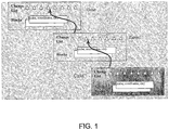
- FIG. 1 shows a hierarchy of base, parent, and child sandboxes. Each sandbox has its own CLEs, and contains a reference back to its respective parent CLE where the snapshot was made.
- the DBMS in accordance with the invention uses a mechanism different from the prior optimistic locking models. Rather than waiting until the end of the transaction (that is, submitting the child sandbox) before doing reconciliation, reconciliation can be performed continuously, since the reconciliation process is deterministic based on the notion that changes in a child sandbox have precedence over those in its parent sandbox. The reconciliation process will be discussed in further detail below.
- a sandbox has an attribute, Snapshot CLN, which specifies a consistency point in a parent sandbox that a child sandbox is consistent with.
- Snapshot CLN specifies a consistency point in a parent sandbox that a child sandbox is consistent with.
- the child sandbox is not supposed to see changes in the parent sandbox that occurs after the Snapshot CLN, until the changes in the child sandbox are reconciled with the parent.
- the system checks whether the evolution crosses the Snapshot CLN. If the evolution does not cross the snapshot CLN, then the block is updated as described above. However, if the evolution crosses the snapshot CLN, then the block is first copied such that the child sandbox will have access to the "stale" block data from the parent sandbox, and then the block is updated as described above.
- a block key has the following components: sandbox id, sparse coordinates, and CLN.
- CLN specifies the version of the block, and ensures that the block has been evolved to this point in logical time. Expressed differently, all prior changes in the log have been applied to the block up to the CLN (or the block does not depend on the changes). Any subsequent changes have not been applied (or the block does not depend on the changes).
- the first method includes retrieving a block with changes from the current sandbox up to the current Sandbox CLN (max CLN).
- the Sandbox CLN is a CLN that is used to represent the "current" point in time in the log, that is, the number of the last log entry for this particular sandbox.
- the other method includes retrieving a block with changes from the current sandbox up to a specific CLN.
- the first method can be reduced to the second method by using the current CLN of the sandbox.
- Pseudo-code for retrieving a block for a sandbox child for a particular CLN is shown in Table 4 below: Table 4
- the first one is through applying changes introduced locally.
- the second way is through on-demand block retrieval for various tasks, such as manipulating analysis spreadsheets, displaying key metrics, and reporting.
- the third way is through child sandbox submissions.
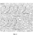
- FIG. 2 shows how a child sandbox is created with a Snapshot CLN1.
- FIG. 2 shows how a child sandbox is created with a Snapshot CLN1.
- Some block revisions can become garbage blocks when a child sandbox is discarded or submitted, or when a new change is introduced that causes a new revision to be generated.
- garbage blocks in a sandbox are collected only when a child sandbox is discarded or submitted, when changes are submitted to the sandbox, or when reconciliation occurs.
- the Snapshot CLNs of all the child sandboxes in ascending order are s 1 , ..., s n where n ⁇ 0.
- the Snapshot CLNs of all the child sandboxes in ascending order are s 1 , ..., s n where n ⁇ 0.
- the Snapshot CLNs of all the child sandboxes in ascending order are s 1 , ..., s n where n ⁇ 0.
- reconciliation can be initiated at any level of sandbox hierarchy and is only needed when the Sandbox CLN is greater than any Snapshot CLN for any child sandbox.
- the sandbox where the reconciliation is initiated the following steps are performed. First, all the garbage blocks are deleted under the assumption that no active child sandboxes exist.
- the sandbox hierarchy is traversed recursively, and for each descendent the following is performed: A new sandbox is created that will be used to replace the descendent.
- the current Sandbox CLN of the parent is taken as the Snapshot CLN.
- Non-internal change entries such as user-initiated changes, are extracted from the old sandbox and a touch list is built. The touch process is then performed, as described above. Finally, the old sandbox is discarded and the new sandbox is associated with the corresponding response. It should be noted that reconciliation is not necessary when there is order independence between the blocks.
- change entries relate to relational databases
- copies are kept of all old columns and all new columns that are necessary, either for doing the mapping to the cubes, or for obtaining data values for the cubes.
- the multiple copies are used when reconciliation occurs.
- Several users may have changed different values located in the same row of the relational database, and these changes need to be merged upon reconciliation. For example, in a relational order database, a first user may have made a change to the quantity of the order and another user may have made a change to a delivery date of the same order. Since both of these pertain to the same order, these changes need to be kept as separate copies until reconciliation, when they are merged.
- a child sandbox can be submitted only when there is no need to reconcile at its parent. Under such a condition, the submission does not require the evolution of the parent blocks by applying the child sandbox changes. Instead, the two sandboxes can be merged, by deleting each of the blocks in the parent sandbox where a block exists in the child sandbox, and re-keying the child sandbox blocks to represent entries in the parent sandbox, by updating their sandbox ids and adjusting their change list number values to represent the point in the merged log.
- garbage blocks are removed, as described above.
- the garbage block removal is followed by a submission of events.
- the submission includes getting IDs of all broken constraints created in the child, marking all broken constraint events created in the child as created in the parent, and using the IDs of all broken constraints to create new records for the child, which are subsequently marked as closed and fixed.
- the broken constraints are submitted by deleting every broken constraint in the parent that has a constraint in the child with the same coordinates, and adding all broken constraints in the child to the parent.
- the Calc CLN is then adjusted for each cube in the parent by the Calc CLN of that cube in the child sandbox.
- the change entries are submitted by cloning change entries from the child sandbox and appending them to the end of the change list of the parent.
- the Sandbox CLN is changed accordingly, which completes the child sandbox submission.
- a block is moved forward not only when they change, but also when the system determines that none of the changes applies to the block.
- the blocks are segmented into a header portion and a data portion, and whenever a block is evolved without changing its data, the data portion remains the same and only the header is moved forward.
- the invention can be implemented in digital electronic circuitry, or in computer hardware, firmware, software, or in combinations of them.
- Apparatus of the invention can be implemented in a computer program product tangibly embodied in a machine-readable medium for execution by a programmable processor.
- machine-readable media include, but are not limited to, magnetic media such as hard disks, floppy disks, and magnetic tape; optical media such as CD-ROM disks and DVDs; magneto-optical media such as floptical disks; and hardware devices that are specially configured to store and perform program instructions, such as read-only memory devices (ROM) and random access memory (RAM).
- the invention can also be embodied in a carrier wave traveling over an appropriate medium such as airwaves, optical lines, electric lines, and so on. Method steps of the invention can be performed by a programmable processor executing a program of instructions to perform functions of the invention by operating on input data and generating output.
- the invention can be implemented advantageously in one or more computer programs that are executable on a programmable system including at least one programmable processor coupled to receive data and instructions from, and to transmit data and instructions to, a data storage system, at least one input device, and at least one output device.
- Each computer program can be implemented in a high-level procedural or object-oriented programming language, or in assembly or machine language if desired; and in any case, the language can be a compiled or interpreted language.
- Suitable processors include, by way of example, both general and special purpose microprocessors. Generally, a processor will receive instructions and data from a read-only memory and/or a random access memory.
- a computer will include one or more mass storage devices for storing data files; such devices include magnetic disks, such as internal hard disks and removable disks; magneto-optical disks; and optical disks.
- Storage devices suitable for tangibly embodying computer program instructions and data include all forms of non-volatile memory, including by way of example semiconductor memory devices, such as EPROM, EEPROM, and flash memory devices; magnetic disks such as internal hard disks and removable disks; magneto-optical disks; and CD-ROM disks. Any of the foregoing can be supplemented by, or incorporated in, ASICs (application-specific integrated circuits).
- ASICs application-specific integrated circuits
- the invention can be implemented on a computer system having a display device such as a monitor or LCD screen for displaying information to the user and a keyboard and a pointing device such as a mouse or a trackball by which the user can provide input to the computer system.
- the computer system can be programmed to provide a graphical user interface through which computer programs interact with users.
Landscapes
- Engineering & Computer Science (AREA)
- Databases & Information Systems (AREA)
- Theoretical Computer Science (AREA)
- Data Mining & Analysis (AREA)
- Physics & Mathematics (AREA)
- General Engineering & Computer Science (AREA)
- General Physics & Mathematics (AREA)
- Information Retrieval, Db Structures And Fs Structures Therefor (AREA)
Description
- The present invention relates to techniques for analyzing large data sets and, more specifically, to methods and apparatus for efficiently running "what if' scenarios with large, multi-dimensional data sets.
- The term "data management software" encompasses a vast array of solutions for manipulation of business data which can be loosely organized into three categories, On-Line Transaction Processing (OLTP), data warehousing, and On-Line Analytical Processing (OLAP). Each of these categories has certain advantages and drawbacks, which were discussed in the above-referenced application.
- In short, OLTP relates to a class of solutions that facilitate and manage transaction-oriented applications, typically for data entry and retrieval transactions in a number of industries including, for example, banking, airlines, mail order, supermarkets, and manufacturing. It is an important goal of an OLTP system that the data stored in the system is readily accessible to ensure a high degree of responsiveness. It is also important to provide locking mechanisms to ensure, for example, that when an individual reserves a resource, e.g., an airline seat, that resource is no longer available to others in the system. Thus, in OLTP systems, storing of data in more than one place is disfavored, emphasizing instead a heavy reliance on joint processing of the different tables to combine data. OLTP systems are very effective for real-time transaction processing, but not particularly suited to reporting functions employing aggregate queries, e.g., show all of the people who are flying on a particular flight more than twice a month.
- Data warehousing employs different data schemas, which are better suited to support relatively sophisticated reporting functions. However, there may be a tremendous amount of duplication of data. In the OLTP context, this duplication is not acceptable, since a change to a single piece of data would need to be duplicated in many places in the data warehouse tables instead of just a single location. On the other hand, data warehousing is advantageous from a reporting perspective in that it allows the creation and maintenance of summary tables which aggregate information which correspond to queries in which a particular business might be particularly interested, for example, passenger loads for specific routes by fiscal quarter. While data warehousing systems are highly optimized to generate static reports, they do not efficiently support analysis of the data in which the questions are not known in advance. For example, a sales manager may look at a static report and see that nationwide sales of a specific product during a particular month were lower than expected. However, because of the static nature of the report, the reason for the shortfall may not be apparent. In such a situation, the sales manager would like to be able to drill down into the data to determine, for example, whether there are any identifiable disparities (e.g., regional, temporal, etc.), which might serve as an explanation. These types of capabilities fall within the domain of OLAP.
- OLAP systems organize data to allow the kind of ad hoc analysis which would allow the sales manager to zero in on the data that might explain the disparity identified in the static report. This is to be contrasted with OLTP solutions which are highly optimized for retrieving detailed data and typically very poor at providing summaries. The OLAP approach is also to be contrasted with data warehousing solutions that would be required to maintain an impracticable number of summary tables to duplicate such functionality. A significant issue with OLAP solutions relates to the fact that they are typically only optimized for batch processing (as opposed to transaction processing which is characterized by near real-time updating). Due to the large amount of highly interdependent summary information in the data underlying an OLAP system, the updating of any piece of detailed data tends to be computationally expensive in that many different summaries on many different levels of the hierarchy will typically need to be invalidated and recalculated. Thus, instead of supporting the interactive updating of data, most OLAP systems typically employ batch recalculations. There are OLAP solutions that attempt to strike various compromises to at least give the appearance of interactive updating. For example, some solutions limit the data set or indices upon it, such that it fits in main memory and then interactively recalculate all data values upon retrieval. Other solutions employ scripting techniques to isolate and update subsets of data between batches. Unfortunately, these approaches only partially mitigate the inefficiencies associated with updating multi-dimensional data sets. As a result, while OLAP systems are effective at the ad-hoc querying of data to assist in identifying and locating issues, they are relatively ineffective at the ad-hoc update or "what-if" scenario analysis needed to understand the implications of making changes to address those identified issues.
- There are a number of techniques by which large, complex data sets may be more efficiently invalidated and recalculated to reflect changes. Change logging is employed in the maintenance of summary information for large data sets, in combination with dependency checking among data blocks for different levels of hierarchical data in such data sets. As a result, the time required to update or recalculate the underlying data is closer to being a function of the number of changes made rather than, as with most OLAP solutions, a function of the size of the data set or the number of dimensions. Furthermore, the described techniques also allow the running of multiple "what if' scenarios using the same underlying data set substantially simultaneously. Different users can run these multiple peer scenarios in parallel. Alternatively, a single user may have multiple levels of scenarios, that is, child scenarios based on the results of a parent scenario, none of which is currently practicable in the conventional OLAP domain. As the complexity of the users' "what if' scenarios increases, there is an increased need for a well-structured system that enables performing changes and updates and that supports rich analytics, compared to what is possible in conventional OLAP systems.
-
US20020065818A discloses a system for developing a customizable electronic records management system to meet the ongoing needs of users of an enterprise application wherein plural control tables are configurable by an expert in the enterprise application. An input/output device enables users to access the control tables, one of which defines a selected output medium. The control tables are populated with prescribed rules provided by the expert for invoking a specific action in response to a user-triggered event. The system enables users to be actively engaged in the development of their business solutions without having to create a costly Information Technology department. - C. Mcgregor et al, 'Oracle Database 2 Day DBA, 10g Release 1 (10.1)', 1 March 2004 is a Oracle (RTM) database user guide. It discloses flashback tables which return a table to a previous state. Dependencies between tables may be retained during the flashback.
- D. Adams, 'Oracle Database Application Developer's Guide - Fundamentals, 10g Release 1 (10.1)', 1 December 2003 discloses the use integrity constraints to enforce business rules. The integrity constraints prevent erroneous data which does not match a pre-determined key from being entered or updated in a table.
- The invention is set out in the appended claims.
-
-
FIG. 1 shows a schematic view of a sandbox hierarchy in accordance with the invention. -
FIG. 2 shows a schematic view of how garbage collection of sandboxes is performed in accordance with the invention. - Like reference symbols in the various drawings indicate like elements.
- Reference will now be made in detail to specific embodiments of the invention including the best modes contemplated by the inventors for carrying out the invention. Examples of these specific embodiments are illustrated in the accompanying drawings. While the invention is described in conjunction with these specific embodiments, it will be understood that the description is not intended to limit the invention to the described embodiments. On the contrary, the description is intended to cover alternatives, modifications, and equivalents as can be included within the scope of the invention as defined by the appended claims. In the following description, specific details are set forth in order to provide a thorough understanding of the present invention. The present invention can be practiced without some or all of these specific details. In addition, well-known features may not have been described in detail to avoid unnecessarily obscuring the invention.
- There are systems and methods that employ change logging in the maintenance of summary information in large data sets, in combination with dependency checking among data blocks for different levels of hierarchical data in such data sets. This approach results in database management system (DBMS) solutions in which the time required to update or recalculate the underlying data is closer to being a function of the number of changes made rather than, as with most OLAP solutions, a function of the size of the data set or the number of dimensions. The techniques can be applied whether the underlying data set corresponds to a relational or multi-dimensional data model. Embodiments of the present invention provide a well-structured format for performing changes and updates enables more complex operations to be performed. As a result, the system and methods of the invention, enables several users to run much more complex "what-if" scenarios than what was previously possible. The following section describes some general characteristics of the system and some basic concepts. A more detailed description of these features can be found in the above referenced patent application.
- According to a specific embodiment of the invention, to facilitate the various techniques described herein, a multi-dimensional data model is employed which organizes data in multi-dimensional cubes. A cube is a multi-dimensional data set. Each data element in a cube is a dimensioned element. Dimensions, which can be sparsely or densely populated, define the number of indices that are used to refer to a data element. A cube said to contain n dimensions uses n indices to define the location of a dimensioned element.
- The number of elements in the cube is the cardinality of the Cartesian product of each of the dimensions in the cube. Cubes have dimensionality equal to the number of dimensions that define the cube. Each dimension contains members, and the dimension itself is also a member. The number of members in a dimension (including the dimension itself) defines the cardinality of the dimension. The number of data elements in the cube is the product of the cardinality of each dimension in the cube. Sparsely populated or "key" dimensions are used as keys to index sets of values in the densely populated or "block" dimensions. Such cube subsets are referred to herein as "blocks." In one embodiment of the present invention, the blocks form the calculation units of the system, that is, the smallest subset of the multi-dimensional data set that is calculated together. The blocks also form input/output (I/O) units. As will be discussed below, since all the data in a block is computed together, this allows for complex operations to be performed within the block, such as calculating a median value. Another interesting consequence of using blocks as computation units is that if a data value within a block can be derived from other data values residing within the block, then that data value does not need to be stored and the system can thus operate more efficiently.
- As previously noted, the multi-dimensional data model employed in the present invention can correspond directly or indirectly to the underlying data set. That is, the underlying data set can be stored in a multi-dimensional database corresponding to the data model described above. Alternatively, the underlying data set can be stored in a multi-dimensional database which corresponds to a different multi-dimensional model, or even as a relational database corresponding to any of a variety of models. In such cases, the underlying database is mapped to a multi-dimensional data model suitable for facilitating the techniques described herein. These mappings will be described in further detail in a separate section below.
- The system and methods described herein use a change list to keep track of modifications made to the data cells. Each modification to a data cell creates a change list entry (CLE). Thus, the application of CLEs from the "beginning of time" to a block results in the current version of that block. An instantiated block on disk has an associated CLE that essentially represents a point in time for the block. To obtain a current version of the block, all CLEs between that point in time and the present are applied.
- Before further discussing the notion of the change list and its operation, it may be useful to reintroduce the notion of "sandboxes." A sandbox is also referred to as a scenario, in which a user performs a "what-if" analysis. The notion of sandboxes forms the support for updates of blocks and updates to the same block in different scenarios, which are sometimes run in parallel. Typically, there is a base scenario or base sandbox and a hierarchy of child sandboxes branching from the base sandbox. Updates made to a particular sandbox may or may not be reflected in other sandboxes, depending on their relation in the hierarchy. The general rules for updating blocks and sandboxes will not be discussed here. However, some special cases relating to "sandbox isolation" will be discussed below. Generally, sandbox isolation refers to the notion of providing sandboxes where users can make changes that are isolated from changes that other users are making in parallel, thus allowing each user to work in their own "world" and study how their own changes affect the underlying data set, even though other users simultaneously may be changing the underlying data set in their separate "world."
- Returning now to the notion of the change list entries, according to a specific embodiment of the invention, a CLE includes the coordinates of the affected cell, a sandbox identifier (ID), a change number, the parent sandbox ID, the parent sandbox change number, the new value, and the delta from the previously calculated value. A current change list number (CLN) is stored with each sandbox. The CLN is a monotonically increasing number and is incremented every time a change is made to a cell in a block in a sandbox. Each block contains the ID of the sandbox it was calculated against, as well as the CLN at that time. Within a sandbox, change list entry numbering is a simple incremental numbering using a sequence number. The original, underlying database is designated as sandbox 0.
- When creating a CLE, the current sandbox CLN is incremented, a new entry for this number is created, and the current parent sandbox CLN is associated with it. Associating the parent CLN facilitates traversing through any ancestors and determining what changes need to be applied to the current sandbox for each parent sandbox. Alternatively, each of the sandbox CLNs can be stored in the block itself. In one embodiment, all the sandbox change lists are arranged within a "master change list" which is a list of all activities that occur within the system.
- When a CLE is created, the new data value is always stored. The difference (also referred to as delta value) from the previous data value is stored when it is a sum or aggregation path value. This occurs when the data value is a leaf-level value along block dimensions, and has sum or count as its aggregation operator along the key dimensions (although it should be noted that aggregation operators are not limited to sum or count). After the CLE is created, the delta value is adjusted for all dependent CLEs. This can be accomplished by filtering for change list entries that have a delta value set, are for the corresponding sandbox or its descendants, and where the members have this member as a dependent.
- Embodiments of the present invention allow dependencies to be defined between members within the same cube and between members in different cubes. Thus, when a block is retrieved from memory, it can be determined with reference to the dependency structure inherent in the data model and with reference to the change list whether a value change in another cube affects any values in this block. In addition, the dependency structure and the change list provide the necessary information to facilitate the transformation of the change information from one cube to another so that the change may be applied in accordance with the dependency. Transformation and application of change information will be discussed in further detail below in a separate section and can be done whether the underlying data source(s) is relational or multi-dimensional.
- The concepts discussed above are best applied to environments wherein the analytic operations between blocks are aggregating operations, such as sum or count. Such operations do not require attention to be paid to complicating elements such as the order of application, other data values outside the ones changed or in the target block, or data-dependent conditional operations. As the skilled reader recognizes, such elements are encountered in sophisticated data analysis, and there is value in extending such analysis to operations across block boundaries. Special care needs to be taken in such situations to ensure data consistency across changes.
- One such situation is when there are multiple arguments involved, such as in the case of a weighted sum. For example, a cost of a product line, expressed in dollars, can be calculated by studying each type of unit in the product line, and multiplying the number of units of the particular type with a unit price for the type of unit, and when all multiplications are done adding the individual results. Whenever the number of units change for any given unit type, or whenever the unit cost changes for one or more of the unit types, this will cause a change to the cost of the product line. Thus, the system must have the capability of addressing such changes. In one embodiment of the invention, this capability is managed by pieces of program code referred to as on-change applicators, which will now be described in further detail.
- In one embodiment of the invention, changes to blocks are applied by on-change applicators, which can be characterized as pieces of program code that specify formulas for how a given change should be applied to a block. Just as a data value can appear as an operand in many different formulas used to calculate other data values, there can be many on-change applicators associated with a given type of CLE. Separating the data contained within a CLE from the program code used to apply the change can be seen to dramatically reduce the number and types of CLEs.
- Generally, the purpose of the on-change applicators is to perform updates to blocks while using data contained in the block itself and the CLE being processed, and not from other blocks. By doing so, the on-change applicator ensures that all data utilized is as of the point in time when the change was originally made, not some earlier or later point in time. This allows a sequence of calculations to be performed with successive change applications wherein the order of application is preserved and resulting in the same data values as if the entire system had been instead invalidated and recalculated with each change. If the change applicator were instead to reference data in other blocks directly, those blocks may be at other points in time from the block being modified, resulting in order inconsistency.
- A number of exemplary scenarios involving on-change attributes will now be discussed. The first scenario relates to a simple case in which a measure, x, summarizes along a dimension s1 (that is, x = sum(children(x))). An on-change expression like the following defines what to do when x changes:

- This example introduces macros for dereferencing data source and target and for getting at parts of a log entry. It can be seen that on-change applicators exemplified by the above example can be used to support aggregating operations such as sum or count.
- The second scenario introduces the situation of a weighted sum described earlier. Here, a demand cube includes product cost aggregated along product lines and computed as the product of unit demand and unit cost. The skilled reader will recognize that both unit demand and unit cost may change over time, that the order of change application must be preserved, and that as each change is processed, the value of the unchanged operand must be available as of the time the change was made to the changed operand. Formulaically, this can be expressed as shown in Table 1 below:
Table 1
      cost = units * unitCost
      <OnChange measure="units"
        formula = "cost = target(cost) + (source(unitCost) *
      source(delta(units)))" />
      <OnChange measure="unit cost"
        formula = "cost = target(cost) + (source(units) *
      source(delta(unitCost)))" />
As can be seen, in general, one on-change expression is required per operand. schedule.pd = demand.pd * rs.allocPct
<OnChange measure="demand.pd"
formula = "schedule.pd = schedule.pd / old(demand.pd) *
new(demand.pd) />
<OnChange measure="rs.allocPct"
formula = "schedule.pd = schedule.pd / old(rs.allocPct) *
new(rs.allocPct) /> 


 /**
 * Retrieve a block for sandbox Child for a particular
 cln
 */
 getBlock(sandboxID, comboKey, expectedCLN)
 Try to locate a block with the sandbox ID, comboKey, and
 cln no greater than expectedCLN.
 If block is found, apply remaining changes when block cln
 is less than cln and return the copy, and
 persist/materialize the copy.
 If such a block cannot be found from the current sandbox,
 recursively find a copy from the parent using
 snapshotCLN. This is the process of taking snapshots.
 Snapshots are not saved.
 This will result either in finding a copy or creating a blank block
 from the base.
 Then apply remaining changes as the recursion rewind.
Claims (4)
- A computer-implemented method for updating a database using a multi-dimensional data model in which data corresponding to the database are organized in multi-dimensional data blocks, each data block having summary information associated therewith corresponding to a current state of evolution of the associated data block, the method comprising:maintaining dependency information in the data model which identifies data dependencies within and among the data blocks;maintaining a list of change entries which identifies changes made to particular ones of the data blocks and times at which the changes were made;receiving a request to apply a change entry to a data block, wherein receiving a request includes receiving a user input value into a cell of a data block that is designated to contain a derived value and monitoring any constraint violations resulting from the user input value until the constraint violations have been resolved, wherein a derived value is a value calculated from a plurality of dependent values;applying the change entry to the data block, including generating a dependency list of data blocks whose data depends from the updated data block; andprocessing the data blocks in the dependency list in accordance with a dependency update algorithm to update the data blocks in the dependency list;wherein processing includes:determining whether the cell with the user input value has any dependent values in one or more other blocks, and when the cell with the user input value has a dependent value in another block, creating a compensating derived change list entry that adjusts the dependent values in the one or more other blocks to resolve a constraint violation; anddetermining whether all values depending from the cell with the user input value are in the same block, and when all values depending from the cell with the user input value are determined to be in the same block, reserving additional disk space for cells that are derived but can be overriden by user input values utilizing a bitmap indicating said values that have been user-specified to ensure that the user input value is not overridden by a derived value.
- The method of claim 1, wherein processing includes processing a data block in the dependency list if the processing of the data block will generate a new change entry.
- The method of any of claims 1 to 2, wherein processing includes processing each data block in the dependency list.
- The method of any of claims 1 to 3, wherein maintaining change information entries includes maintaining a calculation change list number which identifies a point in time at which all change entries have been processed, whereby the calculation change list defines an earliest starting point processing of the data blocks in the dependency list.
Applications Claiming Priority (2)
| Application Number | Priority Date | Filing Date | Title |
|---|---|---|---|
| US11/154,259 US7571192B2 (en) | 2005-06-15 | 2005-06-15 | Methods and apparatus for maintaining consistency during analysis of large data sets |
| PCT/US2006/020494 WO2006138044A2 (en) | 2005-06-15 | 2006-05-24 | Methods and apparatus for maintaining consistency during analysis of large data sets |
Publications (3)
| Publication Number | Publication Date |
|---|---|
| EP1897000A2 EP1897000A2 (en) | 2008-03-12 |
| EP1897000A4 EP1897000A4 (en) | 2011-07-06 |
| EP1897000B1 true EP1897000B1 (en) | 2019-04-24 |
Family
ID=37570944
Family Applications (1)
| Application Number | Title | Priority Date | Filing Date |
|---|---|---|---|
| EP06771328.9A Active EP1897000B1 (en) | 2005-06-15 | 2006-05-24 | Methods and apparatus for maintaining consistency during analysis of large data sets |
Country Status (7)
| Country | Link |
|---|---|
| US (2) | US7571192B2 (en) |
| EP (1) | EP1897000B1 (en) |
| JP (1) | JP2008547086A (en) |
| CN (1) | CN101506804B (en) |
| AU (1) | AU2006259804A1 (en) |
| CA (1) | CA2612391A1 (en) |
| WO (1) | WO2006138044A2 (en) |
Families Citing this family (109)
| Publication number | Priority date | Publication date | Assignee | Title |
|---|---|---|---|---|
| US7613672B2 (en) * | 2006-04-27 | 2009-11-03 | Cardiac Pacemakers, Inc. | Medical device user interface automatically resolving interaction between programmable parameters |
| US8464211B2 (en) | 2007-03-01 | 2013-06-11 | Formotus, Inc. | Forms conversion and deployment system for mobile devices |
| US9430552B2 (en) * | 2007-03-16 | 2016-08-30 | Microsoft Technology Licensing, Llc | View maintenance rules for an update pipeline of an object-relational mapping (ORM) platform |
| US8738573B2 (en) * | 2008-05-23 | 2014-05-27 | Microsoft Corporation | Optimistic versioning concurrency scheme for database streams |
| US8984390B2 (en) | 2008-09-15 | 2015-03-17 | Palantir Technologies, Inc. | One-click sharing for screenshots and related documents |
| AU2010208112B2 (en) * | 2009-01-30 | 2015-05-28 | Ab Initio Technology Llc | Processing data using vector fields |
| US9031987B2 (en) * | 2009-09-30 | 2015-05-12 | Red Hat, Inc. | Propagation of data changes in distribution operations in hierarchical database |
| US8984013B2 (en) | 2009-09-30 | 2015-03-17 | Red Hat, Inc. | Conditioning the distribution of data in a hierarchical database |
| US8996453B2 (en) | 2009-09-30 | 2015-03-31 | Red Hat, Inc. | Distribution of data in a lattice-based database via placeholder nodes |
| US20110078199A1 (en) * | 2009-09-30 | 2011-03-31 | Eric Williamson | Systems and methods for the distribution of data in a hierarchical database via placeholder nodes |
| US8271426B2 (en) | 2009-10-01 | 2012-09-18 | Oracle International Corporation | Change application for datasets using frozen and delta values |
| US8315174B2 (en) * | 2009-12-31 | 2012-11-20 | Red Hat, Inc. | Systems and methods for generating a push-up alert of fault conditions in the distribution of data in a hierarchical database |
| CN102231130B (en) | 2010-01-11 | 2015-06-17 | 国际商业机器公司 | Method and device for analyzing computer system performances |
| US9767136B2 (en) * | 2010-03-31 | 2017-09-19 | Salesforce.Com, Inc. | System, method and computer program product for maintaining data stored in a data structure |
| US9785894B2 (en) | 2010-03-31 | 2017-10-10 | Oracle International Corporation | Simulation of supply chain plans using web service |
| US9740994B2 (en) * | 2010-03-31 | 2017-08-22 | Oracle International Corporation | Simulation of supply chain plans using data model |
| CN102262636B (en) * | 2010-05-25 | 2012-10-10 | 中国移动通信集团浙江有限公司 | Method and device for generating database partition execution plan |
| US9218408B2 (en) * | 2010-05-27 | 2015-12-22 | Oracle International Corporation | Method for automatically creating a data mart by aggregated data extracted from a business intelligence server |
| CN102402559A (en) * | 2010-09-16 | 2012-04-04 | 中兴通讯股份有限公司 | Database upgrade script generating method and device |
| US10360527B2 (en) * | 2010-11-10 | 2019-07-23 | International Business Machines Corporation | Casual modeling of multi-dimensional hierarchical metric cubes |
| US8666997B2 (en) | 2010-12-08 | 2014-03-04 | Microsoft Corporation | Placeholders returned for data representation items |
| US8983907B2 (en) * | 2010-12-08 | 2015-03-17 | Microsoft Technology Licensing, Llc | Change notifications from an updated data representation |
| US9069829B2 (en) | 2011-01-21 | 2015-06-30 | Microsoft Technology Licensing, Llc | Data items manager |
| US9996540B2 (en) * | 2011-03-31 | 2018-06-12 | EMC IP Holding Company LLC | System and method for maintaining consistent points in file systems using a prime dependency list |
| US10210169B2 (en) | 2011-03-31 | 2019-02-19 | EMC IP Holding Company LLC | System and method for verifying consistent points in file systems |
| US9196086B2 (en) | 2011-04-26 | 2015-11-24 | Here Global B.V. | Method, system, and computer-readable data storage device for creating and displaying three-dimensional features on an electronic map display |
| US8838533B2 (en) | 2011-05-20 | 2014-09-16 | Microsoft Corporation | Optimistic application of data edits |
| US9348941B2 (en) * | 2011-06-16 | 2016-05-24 | Microsoft Technology Licensing, Llc | Specification of database table relationships for calculation |
| US9092482B2 (en) | 2013-03-14 | 2015-07-28 | Palantir Technologies, Inc. | Fair scheduling for mixed-query loads |
| CN102222109B (en) * | 2011-06-28 | 2014-05-07 | 用友软件股份有限公司 | Data processing device and method |
| US8732574B2 (en) | 2011-08-25 | 2014-05-20 | Palantir Technologies, Inc. | System and method for parameterizing documents for automatic workflow generation |
| US8504542B2 (en) | 2011-09-02 | 2013-08-06 | Palantir Technologies, Inc. | Multi-row transactions |
| US8560494B1 (en) | 2011-09-30 | 2013-10-15 | Palantir Technologies, Inc. | Visual data importer |
| US9171055B1 (en) * | 2011-10-08 | 2015-10-27 | Bay Dynamics, Inc. | Content packs for multidimensional data storage cubes |
| US9330091B1 (en) | 2011-10-08 | 2016-05-03 | Bay Dynamics, Inc. | System for managing data storages |
| US10353922B1 (en) | 2011-10-08 | 2019-07-16 | Bay Dynamics, Inc. | Rendering multidimensional cube data |
| US8892545B2 (en) * | 2011-12-23 | 2014-11-18 | Sap Se | Generating a compiler infrastructure |
| US9348874B2 (en) * | 2011-12-23 | 2016-05-24 | Sap Se | Dynamic recreation of multidimensional analytical data |
| US8666968B2 (en) * | 2011-12-23 | 2014-03-04 | Sap Ag | Executing runtime callback functions |
| US9378526B2 (en) | 2012-03-02 | 2016-06-28 | Palantir Technologies, Inc. | System and method for accessing data objects via remote references |
| US8849747B2 (en) * | 2012-04-24 | 2014-09-30 | Sap Ag | Business process management |
| US9798768B2 (en) | 2012-09-10 | 2017-10-24 | Palantir Technologies, Inc. | Search around visual queries |
| US9348677B2 (en) | 2012-10-22 | 2016-05-24 | Palantir Technologies Inc. | System and method for batch evaluation programs |
| US9471370B2 (en) | 2012-10-22 | 2016-10-18 | Palantir Technologies, Inc. | System and method for stack-based batch evaluation of program instructions |
| US9367463B2 (en) | 2013-03-14 | 2016-06-14 | Palantir Technologies, Inc. | System and method utilizing a shared cache to provide zero copy memory mapped database |
| US8930897B2 (en) | 2013-03-15 | 2015-01-06 | Palantir Technologies Inc. | Data integration tool |
| US8909656B2 (en) | 2013-03-15 | 2014-12-09 | Palantir Technologies Inc. | Filter chains with associated multipath views for exploring large data sets |
| US8868486B2 (en) | 2013-03-15 | 2014-10-21 | Palantir Technologies Inc. | Time-sensitive cube |
| US8855999B1 (en) | 2013-03-15 | 2014-10-07 | Palantir Technologies Inc. | Method and system for generating a parser and parsing complex data |
| US9740369B2 (en) | 2013-03-15 | 2017-08-22 | Palantir Technologies Inc. | Systems and methods for providing a tagging interface for external content |
| US9898167B2 (en) | 2013-03-15 | 2018-02-20 | Palantir Technologies Inc. | Systems and methods for providing a tagging interface for external content |
| US8903717B2 (en) | 2013-03-15 | 2014-12-02 | Palantir Technologies Inc. | Method and system for generating a parser and parsing complex data |
| US9116953B2 (en) * | 2013-05-17 | 2015-08-25 | Sap Se | Calculation engine with dynamic partitioning of intermediate results |
| US9116960B2 (en) * | 2013-05-17 | 2015-08-25 | Sap Se | Calculation engine with optimized multi-part querying |
| US9984059B2 (en) | 2013-09-27 | 2018-05-29 | Ab Initio Technology Llc | Evaluating rules applied to data |
| US9105000B1 (en) | 2013-12-10 | 2015-08-11 | Palantir Technologies Inc. | Aggregating data from a plurality of data sources |
| CN103778218B (en) * | 2014-01-20 | 2017-01-25 | 浙江省方大标准信息有限公司 | Cloud computation-based standard information consistency early warning system and method |
| US8935201B1 (en) | 2014-03-18 | 2015-01-13 | Palantir Technologies Inc. | Determining and extracting changed data from a data source |
| JP6410932B2 (en) | 2014-06-20 | 2018-10-24 | アマゾン テクノロジーズ インコーポレイテッド | Embedded cloud analytics |
| US9882949B1 (en) | 2014-06-20 | 2018-01-30 | Amazon Technologies, Inc. | Dynamic detection of data correlations based on realtime data |
| US11868372B1 (en) | 2014-06-20 | 2024-01-09 | Amazon Technologies, Inc. | Automated hierarchy detection for cloud-based analytics |
| US10430438B2 (en) | 2014-06-20 | 2019-10-01 | Amazon Technologies, Inc. | Dynamic n-dimensional cubes for hosted analytics |
| US20160026923A1 (en) | 2014-07-22 | 2016-01-28 | Palantir Technologies Inc. | System and method for determining a propensity of entity to take a specified action |
| US20160071226A1 (en) * | 2014-09-05 | 2016-03-10 | Siemens Medical Solutions Usa, Inc. | Method and System for Validating Compliance of Medical Records |
| US20160232470A1 (en) * | 2015-02-05 | 2016-08-11 | Keguo Zhou | Automated Generation of Process Flow Charts |
| US10909178B2 (en) | 2015-03-05 | 2021-02-02 | Workday, Inc. | Methods and systems for multidimensional analysis of interconnected data sets stored in a graph database |
| US9348880B1 (en) | 2015-04-01 | 2016-05-24 | Palantir Technologies, Inc. | Federated search of multiple sources with conflict resolution |
| US10698607B2 (en) * | 2015-05-19 | 2020-06-30 | Netapp Inc. | Configuration update management |
| US9514205B1 (en) | 2015-09-04 | 2016-12-06 | Palantir Technologies Inc. | Systems and methods for importing data from electronic data files |
| US10558339B1 (en) | 2015-09-11 | 2020-02-11 | Palantir Technologies Inc. | System and method for analyzing electronic communications and a collaborative electronic communications user interface |
| US9772934B2 (en) | 2015-09-14 | 2017-09-26 | Palantir Technologies Inc. | Pluggable fault detection tests for data pipelines |
| WO2017070385A1 (en) | 2015-10-23 | 2017-04-27 | Oracle International Corporation | System and method for sandboxing support in a multidimensional database environment |
| US9652510B1 (en) | 2015-12-29 | 2017-05-16 | Palantir Technologies Inc. | Systems and user interfaces for data analysis including artificial intelligence algorithms for generating optimized packages of data items |
| US10554516B1 (en) | 2016-06-09 | 2020-02-04 | Palantir Technologies Inc. | System to collect and visualize software usage metrics |
| US9678850B1 (en) | 2016-06-10 | 2017-06-13 | Palantir Technologies Inc. | Data pipeline monitoring |
| US10621314B2 (en) | 2016-08-01 | 2020-04-14 | Palantir Technologies Inc. | Secure deployment of a software package |
| US10133782B2 (en) | 2016-08-01 | 2018-11-20 | Palantir Technologies Inc. | Techniques for data extraction |
| US11256762B1 (en) | 2016-08-04 | 2022-02-22 | Palantir Technologies Inc. | System and method for efficiently determining and displaying optimal packages of data items |
| US10552531B2 (en) | 2016-08-11 | 2020-02-04 | Palantir Technologies Inc. | Collaborative spreadsheet data validation and integration |
| US10373078B1 (en) | 2016-08-15 | 2019-08-06 | Palantir Technologies Inc. | Vector generation for distributed data sets |
| EP3282374A1 (en) | 2016-08-17 | 2018-02-14 | Palantir Technologies Inc. | User interface data sample transformer |
| US10650086B1 (en) | 2016-09-27 | 2020-05-12 | Palantir Technologies Inc. | Systems, methods, and framework for associating supporting data in word processing |
| US10152306B2 (en) | 2016-11-07 | 2018-12-11 | Palantir Technologies Inc. | Framework for developing and deploying applications |
| US10261763B2 (en) | 2016-12-13 | 2019-04-16 | Palantir Technologies Inc. | Extensible data transformation authoring and validation system |
| US11157951B1 (en) | 2016-12-16 | 2021-10-26 | Palantir Technologies Inc. | System and method for determining and displaying an optimal assignment of data items |
| US10509844B1 (en) | 2017-01-19 | 2019-12-17 | Palantir Technologies Inc. | Network graph parser |
| US10180934B2 (en) | 2017-03-02 | 2019-01-15 | Palantir Technologies Inc. | Automatic translation of spreadsheets into scripts |
| US10572576B1 (en) | 2017-04-06 | 2020-02-25 | Palantir Technologies Inc. | Systems and methods for facilitating data object extraction from unstructured documents |
| US10824604B1 (en) | 2017-05-17 | 2020-11-03 | Palantir Technologies Inc. | Systems and methods for data entry |
| US10534595B1 (en) | 2017-06-30 | 2020-01-14 | Palantir Technologies Inc. | Techniques for configuring and validating a data pipeline deployment |
| US10204119B1 (en) | 2017-07-20 | 2019-02-12 | Palantir Technologies, Inc. | Inferring a dataset schema from input files |
| US10754820B2 (en) | 2017-08-14 | 2020-08-25 | Palantir Technologies Inc. | Customizable pipeline for integrating data |
| CN107506147B (en) * | 2017-08-29 | 2020-05-29 | 郑州云海信息技术有限公司 | Method and system for keeping consistency of metadata |
| US11016936B1 (en) | 2017-09-05 | 2021-05-25 | Palantir Technologies Inc. | Validating data for integration |
| US11379525B1 (en) | 2017-11-22 | 2022-07-05 | Palantir Technologies Inc. | Continuous builds of derived datasets in response to other dataset updates |
| US10552524B1 (en) | 2017-12-07 | 2020-02-04 | Palantir Technolgies Inc. | Systems and methods for in-line document tagging and object based data synchronization |
| US10783162B1 (en) | 2017-12-07 | 2020-09-22 | Palantir Technologies Inc. | Workflow assistant |
| US10360252B1 (en) | 2017-12-08 | 2019-07-23 | Palantir Technologies Inc. | Detection and enrichment of missing data or metadata for large data sets |
| US11176116B2 (en) | 2017-12-13 | 2021-11-16 | Palantir Technologies Inc. | Systems and methods for annotating datasets |
| US10853352B1 (en) | 2017-12-21 | 2020-12-01 | Palantir Technologies Inc. | Structured data collection, presentation, validation and workflow management |
| GB201800595D0 (en) | 2018-01-15 | 2018-02-28 | Palantir Technologies Inc | Management of software bugs in a data processing system |
| US10599762B1 (en) | 2018-01-16 | 2020-03-24 | Palantir Technologies Inc. | Systems and methods for creating a dynamic electronic form |
| US10885021B1 (en) | 2018-05-02 | 2021-01-05 | Palantir Technologies Inc. | Interactive interpreter and graphical user interface |
| US11263263B2 (en) | 2018-05-30 | 2022-03-01 | Palantir Technologies Inc. | Data propagation and mapping system |
| US11061542B1 (en) | 2018-06-01 | 2021-07-13 | Palantir Technologies Inc. | Systems and methods for determining and displaying optimal associations of data items |
| US10795909B1 (en) | 2018-06-14 | 2020-10-06 | Palantir Technologies Inc. | Minimized and collapsed resource dependency path |
| US11651274B2 (en) * | 2019-07-10 | 2023-05-16 | Here Global B.V. | Method, apparatus, and system for providing semantic filtering |
| US20220019910A1 (en) * | 2020-07-20 | 2022-01-20 | Cigna Intellectual Property, Inc. | Computer-automated analysis and validation systems for data models |
| CN114912427A (en) * | 2021-02-10 | 2022-08-16 | 微软技术许可有限责任公司 | Data sheet analysis in response to user input |
Family Cites Families (18)
| Publication number | Priority date | Publication date | Assignee | Title |
|---|---|---|---|---|
| US5497486A (en) * | 1994-03-15 | 1996-03-05 | Salvatore J. Stolfo | Method of merging large databases in parallel |
| EP0823092A1 (en) * | 1995-04-24 | 1998-02-11 | Aspect Development, Inc. | Modeling of object-oriented database structures, translation to relational database structures, and dynamic searches thereon |
| US5907711A (en) * | 1996-01-22 | 1999-05-25 | Hewlett-Packard Company | Method and apparatus for transforming multiplications into product table lookup references |
| US6205447B1 (en) * | 1997-06-30 | 2001-03-20 | International Business Machines Corporation | Relational database management of multi-dimensional data |
| US6035306A (en) * | 1997-11-24 | 2000-03-07 | Terascape Software Inc. | Method for improving performance of large databases |
| JP3436879B2 (en) * | 1998-03-05 | 2003-08-18 | 松下電器産業株式会社 | Distance detecting method and device |
| US6493699B2 (en) * | 1998-03-27 | 2002-12-10 | International Business Machines Corporation | Defining and characterizing an analysis space for precomputed views |
| JP3004008B1 (en) * | 1998-10-20 | 2000-01-31 | 三菱電機株式会社 | Update history management device and update history management method |
| US6263334B1 (en) * | 1998-11-11 | 2001-07-17 | Microsoft Corporation | Density-based indexing method for efficient execution of high dimensional nearest-neighbor queries on large databases |
| CA2281331A1 (en) * | 1999-09-03 | 2001-03-03 | Cognos Incorporated | Database management system |
| US6393434B1 (en) * | 1999-09-14 | 2002-05-21 | International Business Machines Corporation | Method and system for synchronizing data using fine-grained synchronization plans |
| US6542883B1 (en) * | 2000-03-09 | 2003-04-01 | International Business Machines Corporation | Ordering relational database operations according to referential integrity constraints |
| US20020065818A1 (en) * | 2000-08-23 | 2002-05-30 | Starr Ronald E. | Computerized method and applications generator system for developing a customizable electronic records management system |
| CA2361242C (en) * | 2001-11-02 | 2010-11-30 | Cognos Incorporated | A calculation engine for use in olap environments |
| US20030149571A1 (en) * | 2002-02-01 | 2003-08-07 | Steve Francesco | System and method for facilitating decision making in scenario development |
| US6898608B2 (en) * | 2002-04-26 | 2005-05-24 | Oracle International Corporation | Techniques for managing what-if analysis of data managed by a relational database system |
| CN1856783B (en) * | 2002-07-26 | 2011-05-25 | 罗恩·埃弗里特 | Data management structure associated with general data item |
| US7647356B2 (en) * | 2004-05-07 | 2010-01-12 | Oracle International Corporation | Methods and apparatus for facilitating analysis of large data sets |
-
2005
- 2005-06-15 US US11/154,259 patent/US7571192B2/en active Active
-
2006
- 2006-05-24 JP JP2008516894A patent/JP2008547086A/en active Pending
- 2006-05-24 CA CA002612391A patent/CA2612391A1/en not_active Abandoned
- 2006-05-24 CN CN2006800298283A patent/CN101506804B/en active Active
- 2006-05-24 AU AU2006259804A patent/AU2006259804A1/en not_active Abandoned
- 2006-05-24 EP EP06771328.9A patent/EP1897000B1/en active Active
- 2006-05-24 WO PCT/US2006/020494 patent/WO2006138044A2/en active Application Filing
-
2009
- 2009-06-18 US US12/486,979 patent/US8069146B2/en active Active
Non-Patent Citations (2)
| Title |
|---|
| COLIN MCGREGOR: "Oracle Database 2 Day DBA 10g Release 1 (10.1)", 1 March 2004 (2004-03-01), XP055394280, Retrieved from the Internet <URL:http://docs.oracle.com/pdf/B10742_02.pdf> [retrieved on 20170727] * |
| DREW ADAMS ET AL: "Oracle Database Application Developer's Guide -Fundamentals 10g Release 1 (10.1)", 1 December 2003 (2003-12-01), XP055394289, Retrieved from the Internet <URL:https://docs.oracle.com/cd/B12037_01/appdev.101/b10795.pdf> [retrieved on 20170727] * |
Also Published As
| Publication number | Publication date |
|---|---|
| CN101506804B (en) | 2013-01-16 |
| CA2612391A1 (en) | 2006-12-28 |
| US7571192B2 (en) | 2009-08-04 |
| CN101506804A (en) | 2009-08-12 |
| AU2006259804A1 (en) | 2006-12-28 |
| US20090259695A1 (en) | 2009-10-15 |
| US8069146B2 (en) | 2011-11-29 |
| EP1897000A4 (en) | 2011-07-06 |
| US20060288046A1 (en) | 2006-12-21 |
| JP2008547086A (en) | 2008-12-25 |
| WO2006138044A2 (en) | 2006-12-28 |
| EP1897000A2 (en) | 2008-03-12 |
| WO2006138044A3 (en) | 2009-04-30 |
Similar Documents
| Publication | Publication Date | Title |
|---|---|---|
| EP1897000B1 (en) | Methods and apparatus for maintaining consistency during analysis of large data sets | |
| US7647356B2 (en) | Methods and apparatus for facilitating analysis of large data sets | |
| Inmon et al. | DW 2.0: The architecture for the next generation of data warehousing | |
| Malinowski et al. | Hierarchies in a multidimensional model: From conceptual modeling to logical representation | |
| Refaat | Data preparation for data mining using SAS | |
| Carey et al. | Data-Centric Systems and Applications | |
| Golfarelli et al. | Designing the data warehouse: Key steps and crucial issues | |
| US8099383B2 (en) | Apparatus and method for defining report parts | |
| US8311975B1 (en) | Data warehouse with a domain fact table | |
| EP1843286A1 (en) | Report management system | |
| US20110060753A1 (en) | Methods for effective processing of time series | |
| CN107533569B (en) | System and method for sandbox support in a multidimensional database environment | |
| CN104731791A (en) | Marketing analysis data market system | |
| JPH04217042A (en) | Physical-database designing system | |
| Holubová et al. | Evolution Management of Multi-model Data: (Position Paper) | |
| Albano | Decision support databases essentials | |
| Bender et al. | A proposal for future data organization in enterprise systems—an analysis of established database approaches | |
| Moukhi et al. | Towards a new method for designing multidimensional models | |
| Golfarelli et al. | Vertical Fragmentation of Views in Relational Data Warehouses. | |
| Ravat et al. | OLAP analysis operators for multi-state data warehouses | |
| Vaisman et al. | Data warehouse concepts | |
| Klauck et al. | Interactive, flexible, and generic what-if analyses using in-memory column stores | |
| Alur et al. | DB2 UDB's High-Function Business Intelligence in E-business | |
| Moustafa Essa | the Change from Data Warehousing to Business Intelligence: The Concept of Data Sources' Dynamicity | |
| Meier et al. | Postrelational Databases |
Legal Events
| Date | Code | Title | Description |
|---|---|---|---|
| PUAI | Public reference made under article 153(3) epc to a published international application that has entered the european phase |
Free format text: ORIGINAL CODE: 0009012 |
|
| 17P | Request for examination filed |
Effective date: 20080102 |
|
| AK | Designated contracting states |
Kind code of ref document: A2 Designated state(s): AT BE BG CH CY CZ DE DK EE ES FI FR GB GR HU IE IS IT LI LT LU LV MC NL PL PT RO SE SI SK TR |
|
| AX | Request for extension of the european patent |
Extension state: AL BA HR MK YU |
|
| RAP1 | Party data changed (applicant data changed or rights of an application transferred) |
Owner name: ORACLE INTERNATIONAL CORPORATION |
|
| DAX | Request for extension of the european patent (deleted) | ||
| RBV | Designated contracting states (corrected) |
Designated state(s): DE FR GB NL |
|
| REG | Reference to a national code |
Ref country code: HK Ref legal event code: DE Ref document number: 1114195 Country of ref document: HK |
|
| R17D | Deferred search report published (corrected) |
Effective date: 20090430 |
|
| A4 | Supplementary search report drawn up and despatched |
Effective date: 20110607 |
|
| 17Q | First examination report despatched |
Effective date: 20170306 |
|
| GRAP | Despatch of communication of intention to grant a patent |
Free format text: ORIGINAL CODE: EPIDOSNIGR1 |
|
| INTG | Intention to grant announced |
Effective date: 20181121 |
|
| GRAS | Grant fee paid |
Free format text: ORIGINAL CODE: EPIDOSNIGR3 |
|
| GRAA | (expected) grant |
Free format text: ORIGINAL CODE: 0009210 |
|
| AK | Designated contracting states |
Kind code of ref document: B1 Designated state(s): DE FR GB NL |
|
| REG | Reference to a national code |
Ref country code: GB Ref legal event code: FG4D |
|
| REG | Reference to a national code |
Ref country code: DE Ref legal event code: R096 Ref document number: 602006057828 Country of ref document: DE |
|
| REG | Reference to a national code |
Ref country code: NL Ref legal event code: MP Effective date: 20190424 |
|
| PG25 | Lapsed in a contracting state [announced via postgrant information from national office to epo] |
Ref country code: NL Free format text: LAPSE BECAUSE OF FAILURE TO SUBMIT A TRANSLATION OF THE DESCRIPTION OR TO PAY THE FEE WITHIN THE PRESCRIBED TIME-LIMIT Effective date: 20190424 |
|
| REG | Reference to a national code |
Ref country code: DE Ref legal event code: R097 Ref document number: 602006057828 Country of ref document: DE |
|
| PLBE | No opposition filed within time limit |
Free format text: ORIGINAL CODE: 0009261 |
|
| STAA | Information on the status of an ep patent application or granted ep patent |
Free format text: STATUS: NO OPPOSITION FILED WITHIN TIME LIMIT |
|
| 26N | No opposition filed |
Effective date: 20200127 |
|
| PG25 | Lapsed in a contracting state [announced via postgrant information from national office to epo] |
Ref country code: FR Free format text: LAPSE BECAUSE OF NON-PAYMENT OF DUE FEES Effective date: 20190624 |
|
| PGFP | Annual fee paid to national office [announced via postgrant information from national office to epo] |
Ref country code: GB Payment date: 20230330 Year of fee payment: 18 |
|
| P01 | Opt-out of the competence of the unified patent court (upc) registered |
Effective date: 20230523 |
|
| PGFP | Annual fee paid to national office [announced via postgrant information from national office to epo] |
Ref country code: DE Payment date: 20230331 Year of fee payment: 18 |