EP1896873B1 - Apparatus and method for providing communication between a probe and a sensor - Google Patents
Apparatus and method for providing communication between a probe and a sensor Download PDFInfo
- Publication number
- EP1896873B1 EP1896873B1 EP06773485.5A EP06773485A EP1896873B1 EP 1896873 B1 EP1896873 B1 EP 1896873B1 EP 06773485 A EP06773485 A EP 06773485A EP 1896873 B1 EP1896873 B1 EP 1896873B1
- Authority
- EP
- European Patent Office
- Prior art keywords
- probe
- antenna coil
- coil winding
- sensor
- antenna
- Prior art date
- Legal status (The legal status is an assumption and is not a legal conclusion. Google has not performed a legal analysis and makes no representation as to the accuracy of the status listed.)
- Active
Links
- 239000000523 sample Substances 0.000 title claims description 145
- 238000000034 method Methods 0.000 title claims description 23
- 238000004891 communication Methods 0.000 title description 17
- 238000004804 winding Methods 0.000 claims description 65
- 230000004323 axial length Effects 0.000 claims description 16
- 238000005553 drilling Methods 0.000 claims description 15
- 239000012530 fluid Substances 0.000 claims description 15
- 230000005251 gamma ray Effects 0.000 claims description 8
- 238000012545 processing Methods 0.000 claims description 8
- 230000035945 sensitivity Effects 0.000 claims description 4
- 230000004044 response Effects 0.000 claims description 2
- 230000005540 biological transmission Effects 0.000 description 12
- 238000010586 diagram Methods 0.000 description 11
- 230000002457 bidirectional effect Effects 0.000 description 6
- 238000010276 construction Methods 0.000 description 6
- 238000005259 measurement Methods 0.000 description 6
- 230000008901 benefit Effects 0.000 description 5
- 230000008878 coupling Effects 0.000 description 5
- 238000010168 coupling process Methods 0.000 description 5
- 238000005859 coupling reaction Methods 0.000 description 5
- 239000003302 ferromagnetic material Substances 0.000 description 5
- 230000001965 increasing effect Effects 0.000 description 5
- 230000001902 propagating effect Effects 0.000 description 4
- 230000015572 biosynthetic process Effects 0.000 description 3
- 238000000926 separation method Methods 0.000 description 3
- RYGMFSIKBFXOCR-UHFFFAOYSA-N Copper Chemical compound [Cu] RYGMFSIKBFXOCR-UHFFFAOYSA-N 0.000 description 2
- XEEYBQQBJWHFJM-UHFFFAOYSA-N Iron Chemical compound [Fe] XEEYBQQBJWHFJM-UHFFFAOYSA-N 0.000 description 2
- 239000004696 Poly ether ether ketone Substances 0.000 description 2
- 230000003321 amplification Effects 0.000 description 2
- 238000010420 art technique Methods 0.000 description 2
- 239000012141 concentrate Substances 0.000 description 2
- 239000004020 conductor Substances 0.000 description 2
- 238000013461 design Methods 0.000 description 2
- 230000001939 inductive effect Effects 0.000 description 2
- 230000005291 magnetic effect Effects 0.000 description 2
- 238000003199 nucleic acid amplification method Methods 0.000 description 2
- 230000010363 phase shift Effects 0.000 description 2
- 229920002530 polyetherether ketone Polymers 0.000 description 2
- 238000012360 testing method Methods 0.000 description 2
- 229910000831 Steel Inorganic materials 0.000 description 1
- 229910052802 copper Inorganic materials 0.000 description 1
- 239000010949 copper Substances 0.000 description 1
- 230000003247 decreasing effect Effects 0.000 description 1
- 230000000694 effects Effects 0.000 description 1
- 230000005670 electromagnetic radiation Effects 0.000 description 1
- 239000011152 fibreglass Substances 0.000 description 1
- 229930195733 hydrocarbon Natural products 0.000 description 1
- 150000002430 hydrocarbons Chemical class 0.000 description 1
- 229910052742 iron Inorganic materials 0.000 description 1
- 239000000463 material Substances 0.000 description 1
- 239000012811 non-conductive material Substances 0.000 description 1
- 230000008569 process Effects 0.000 description 1
- 230000009467 reduction Effects 0.000 description 1
- 239000010959 steel Substances 0.000 description 1
- 230000001360 synchronised effect Effects 0.000 description 1
- 238000012546 transfer Methods 0.000 description 1
- 229910000859 α-Fe Inorganic materials 0.000 description 1
Images


Classifications
-
- G—PHYSICS
- G01—MEASURING; TESTING
- G01V—GEOPHYSICS; GRAVITATIONAL MEASUREMENTS; DETECTING MASSES OR OBJECTS; TAGS
- G01V11/00—Prospecting or detecting by methods combining techniques covered by two or more of main groups G01V1/00 - G01V9/00
- G01V11/002—Details, e.g. power supply systems for logging instruments, transmitting or recording data, specially adapted for well logging, also if the prospecting method is irrelevant
-
- E—FIXED CONSTRUCTIONS
- E21—EARTH OR ROCK DRILLING; MINING
- E21B—EARTH OR ROCK DRILLING; OBTAINING OIL, GAS, WATER, SOLUBLE OR MELTABLE MATERIALS OR A SLURRY OF MINERALS FROM WELLS
- E21B47/00—Survey of boreholes or wells
- E21B47/12—Means for transmitting measuring-signals or control signals from the well to the surface, or from the surface to the well, e.g. for logging while drilling
- E21B47/13—Means for transmitting measuring-signals or control signals from the well to the surface, or from the surface to the well, e.g. for logging while drilling by electromagnetic energy, e.g. radio frequency
Definitions
- This invention relates to an apparatus that provides communication between a probe and a sensor. More particularly, but not by way of limitation, this invention relates to an apparatus and method that provides communication between a probe located in the central bore of a drill collar and sensor electronics located in the drill collar wall.
- the probe may contain various sensors such as resistivity, gamma ray, gamma density, neutron porosity, pressure, etc. As those of ordinary skill in the art will recognize, the probes may be lowered in open hole situations intermittent of drilling operations, or in post drilling applications where the well contains casing. These type of operations are commonly referred to as well logging.
- LWD logging while drilling
- MWD measurement while drilling
- Both the LWD and MWD devices employ sensors that collects specific types of information, and wherein that information is transferred to a down hole processor.
- the down hole processor in turn transmits the information to the surface.
- the transmission media may be a cable that electrically connects the down hole processor to a surface processor.
- the transmission media may be the fluid column in the well, and wherein the down hole device contains a vibrating valve that transmits coded fluid pressure pulses that will be decoded at the surface.
- the MWD sensors are placed in a cylindrical probe that is located in the central bore of the drill collar. Theses sensors are not affected by the steel of the surrounding drill collar and are able to make measurements continuously while drilling. However, some of the LWD sensors and some of the newer generation MWD sensors can be strongly affected by the surrounding drill collar and have to be located in the external wall of the drill collar. Examples of LWD/MWD measurements that are affected by the drill collar are resistivity, annulus pressure, gamma density, and to some extent natural gamma ray. Quite often the drilling operation will make use of both MWD and LWD measurement systems. In these situations there can be sensors located in both the probe positioned in the central bore of the drill collar and sensors located in the external wall of the drill collar. As a result, some form of communication is required between these sensor systems to coordinate the measurement functions and transmit data to the surface.
- the apparatus includes a sensor means, positioned within a pocket in a tubular string, for collecting information of the characteristic and processing the information, a first modem means for modulating the information from the sensor means into a signal, and a sensor antenna electrically connected to the first modem means for generating an electromagnetic wave.
- the apparatus further includes a probe antenna, concentrically disposed within the tubular string, for receiving the electromagnetic wave, and, a second modem means for demodulating the electromagnetic wave into the information.
- the sensor means may measure the following properties: resistivity; gamma ray; or pressure.
- the sensor means may include a circuit for collecting an analog signal and generating a digital record.
- the operating frequency range of the sensor antenna and the probe antenna is between 10,000 hertz and 100,000 hertz.
- the connection between the modem means and the probe means is a universal asynchronous receiver/transmitter (UART) interface, and the protocol of the UART is the RS 232 standard. Also, in one embodiment, there is some overlap in the axial direction of the probe antenna and the sensor antenna.
- UART universal asynchronous receiver/transmitter
- the probe antenna is disposed about the outer periphery of the probe, and the sensor antenna is disposed about the inner tubular string.
- the length of one of the antennas is longer than then length of the other antenna so that the electromagnetic coupling between the antennas is less sensitive to axial misalignment of the two antennas. This makes positioning of the probe in the center bore of the collar less problematic.
- the well bore may contain a fluid column, and wherein the probe drives a fluid valve that transmits fluid pressure pulses indicative of the measured properties.
- a method for communicating a sensor located within a tubing string with a probe concentrically disposed within the tubing string comprises providing the sensor located within the tubing string, generating a reading from the sensor, and transmitting the reading to a first modem means. Next, the reading is converted to a modulated signal, and the modulated signal is directed to a tubing string antenna located within the tubing string, and an electromagnetic signal is generated with the tubing string antenna in response to the reading from the sensor.
- the method includes receiving the propagating wave with a probe antenna located within the probe, and demodulating the electromagnetic wave (signal) within a second modem means to the reading.
- the reading is transmitted to a probe electronics module located within the probe.
- the sensor measures the characteristics of resistivity, gamma ray or pressure.
- the step of generating the reading from the sensor may include collecting an analog signal within a circuit and generating a digital record from the analog signal.
- an apparatus for communicating a sensor with a control unit comprises a housing containing the sensor, with the first housing having an opening therein, and a probe, slidably disposed within the opening.
- the apparatus includes a first circuit means, disposed within the housing, for receiving a reading generated by the sensor and generating an output reading, a first modem means, electrically connected with the first circuit means, for demodulating the output reading, and a housing antenna, electrically connected with the first modem means, for generating a modulated electromagnetic wave.
- the second embodiment further includes a probe antenna, disposed about the probe, for receiving the modulated electromagnetic wave, a second modem means, electrically connected with the probe antenna, for converting the electromagnetic wave to the output reading, and a second circuit means, electrically connected with the second modem means and positioned within the probe, for processing and recording the output reading into a digital record.
- the probe antenna can generate modulated electromagnetic waves and wherein the housing antenna can receive the modulated electromagnetic waves.
- the second circuit means can generate an output command that is received by the second modem means, and wherein the second modem means modulates the output command that is received by the probe antenna for generation of the modulated electromagnetic wave, which in turn will be received by the housing antenna.
- the probe antenna is disposed about the periphery of the probe, and the probe antenna comprises a non-metallic coil form; an antenna winding about the coil form, and a non-metallic shield covering the antenna winding.
- the housing antenna may comprise a non-metallic coil form that is adjacent an inner pocket; an antenna winding placed about the non-metallic coil form; and a non-metallic shield covering the antenna winding.
- probe and sensor electronics are located in separate sealed pressure housings, a wired connection between them is problematic.
- An advantage of the present invention is that it allows bi-directional transfer of data between the probe and sensor electronics without the use of wires.
- the wireless communication link overcomes the prior art problems and eliminates the complexities of connecting wires between the probe and the collar electronics in the field.
- Another advantage is that the disclosed method and apparatus allows a simple and cleaner field tool make-up, and wherein no wired connections are required to be made in the field. Also, another advantage of the disclosed method is a decreased sensitivity to axial misalignment of the probe inside the collar bore when the axial length of one of the antennas is extended to provide larger tolerance of axial alignment of the two antennas. Yet another advantage is that no pressure feed-thrus are required to route wiring between the probe and the collar.
- a feature of the present invention is that the apparatus uses electromagnetic radiation to establish the communication link. Another feature is that the probe and drill-collar instrumentation are in completely separate pressure containers reducing the risk of flooding both devices should one pressure container develop a leak. Yet another feature is that there are fewer mechanical intrusions into the fluid flowing through the center of the drill collar.
- a tubular member 2 such as a drill collar
- the drill collar 2 has an internal diameter portion 6, and wherein the probe 8, which is generally cylindrical, is slidably disposed within the internal diameter portion 6.
- the drill collar 2 may be connected to a drill bit used for boring a bore hole.
- the probe 8 may be operatively associated with a MWD tool or LWD tool (not shown).
- the MWD tool can create a pressure pulse that duplicates a digital code transmission thereby allowing the transmission of down hole data to the surface.
- MWD and LWD tools are commercially available from Baker Hughes Inc. It should also be noted that the probe 8 may be connected via a hard wired cable, known in the industry as electric line, and wherein the transmission path of the electrical signals is the electric line.
- the pressure pulse valve is denoted by the numeral 9.
- Fig. 1 depicts the apparatus, seen generally at 10, and wherein the apparatus 10 consists of two modem electronic modules and two antennas. More specifically, the first modem electronics module 12 and the probe antenna 14 are located in the probe 8. The probe antenna 14 is located on the outer periphery of the probe 8, underneath a non-conducting sleeve 16. This non-conductive sleeve 16 protects the probe antenna 14 from the drilling fluid flowing through the internal diameter portion 6 of the drill collar 2.
- the apparatus 10 further includes a second modem electronics module 18 and drill collar antenna 20 (sometimes referred to as the tubing antenna 20) located in the drill collar 2.
- the drill collar antenna 20 is located in a pocket 22 on the inside diameter portion of the drill collar 2. This pocket 22 is filled with a non-conducting material that covers the drill collar antenna 20 and protects it from the drilling fluid flowing through the inside of the drill collar 2. Because the sleeve 16 covering the probe antenna 14 and the pocket material covering the drill-collar antenna 20 are non-conductive, electromagnetic (EM) signals can pass between the two antennas and allow a wireless data communications link to be established between the probe electronics 24 and the sensor electronics 26.
- the probe electronics 24 allow for the processing, storage and bidirectional transmission of data with the first modem electronics module 12.
- the sensor electronics 26 collects information received from the various types of down hole sensors available such as resistivity, gamma ray, pressure, etc., and the sensor electronics 26 further allows for the bidirectional transmission of this data with the second modem electronics module 18.
- the first modem electronic module 12 and second modem electronic module 18 of the apparatus-system 10 will use the same electronic design. This allows the same modem module to be used for either position in the down hole tool.
- the connection between the modem electronic modules and the rest of the down hole tool system will utilize a Universal Asynchronous Receiver Transmitter (UART) interface.
- UART Universal Asynchronous Receiver Transmitter
- the sensor electronics 26 will employ a UART chip and the probe electronics 24 will also employ a UART chip.
- the interface between the electronic modules and the modem modules will employ the RS-232 standard for serial communication, as seen by the link 27a between the probe electronics 24 and the first modem electronics module 12, as well as the RS-232 link 27b between the sensor electronics 26 and the second modem electronics module 18.
- the apparatus 10 operates as a simple modulator-demodulator (modem) transferring the transmit data and the receive data signals of the UART interface across the EM link.
- the signal levels on the UART interface will be +5V logic levels, allowing the modem modules (namely modem electronics modules 12, 18) to be wired directly to standard UART that are embedded in most microprocessors.
- Attenuation of EM signals propagating in the internal bore of a drill-collar can be extremely high.
- the probe antenna 14 and the drill collar antenna 20 will be located coaxial with the axial center points of the antennas located in the same plane, as seen in Fig. 1 . This configuration reduces the EM signal attenuation and provides the lowest error rate possible for the data transmitted through the apparatus system 10.
- a sensor 32 will collect data such as resistivity of the formation fluids.
- the sensor 32 may also collect information on the gamma ray counts of the formation, the pressure of the well bore, and other properties as well understood by those of ordinary skill in the art.
- the sensor 32 is physically located within the drill collar.
- the sensor 32 may include a circuit means for collecting an analog signal and generating a record.
- the data collected by the sensor 32 is transmitted to the collar sensor electronics 34, and wherein the collar sensor electronics 34 includes a processor for receiving a reading generated by the sensor, processing the data signals from the sensor 32, and generating a digital output.
- the digital data will then be sent to the modem 36 (sometimes referred to as a transceiver 36).
- the modem means 36 includes a bit frame generator 37 that receives the digital data and formats the serial data stream for a modulator 38 that in turn will deliver the signal to the transmitter amplifier 40.
- the analog signal will be delivered to the antenna 42, wherein the antenna 42 is a radio frequency transducer.
- the antenna 42 is a coil of wire and the antenna will transmit the electromagnetic waves to a receiving antenna seen in Fig. 2B .
- Fig. 10 a cross-sectional diagram of one of the preferred embodiments of the antenna is illustrated.
- the antennas are wound on coil forms fabricated with a non-metallic or non-conductive material such as fiberglass or polyetheretherketone (PEEK).
- PEEK polyetheretherketone
- the probe 8 is disposed within the drill collar 2.
- This view shows the non-metallic coil form 120 disposed about the drill collar 2, as well as the antenna windings 122 disposed on the outer periphery of the drill collar 2.
- the non-metallic shield 124 covers and shields the antenna windings 122.
- Fig. 10 also shows the probe antenna windings 126, placed about the non-metallic coil form 128.
- Fig. 10 further depicts the non-metallic shield 130 for covering the antenna winding 126.Winding the wire of the antenna on this type of coil form reduces eddy current losses and improves the efficiency of the antenna by spacing the antenna away from the conductive materials of the collar and probe.
- the antennas are constructed without the use of soft ferro-magnetic materials like soft iron or ferrite. Soft ferro-magnetic materials are typically used to concentrate the magnetic field through the coil windings and increase the inductive coupling between the two antennas.
- the antennas of the present invention are manufactured from copper. -Eliminating the need for these ferro-magnetic materials in this antenna design allows a larger tolerance for alignment of the coils and makes the system more tolerant to axial misalignment of the two antennas.
- the system herein described is also bidirectional.
- the antenna 42 can also receive electromagnetic waves and directed the analog signal to the modem means 36, and in particular to the receiver amplifier 44.
- the resulting signal is therefore amplified with the receiver amplifier 44.
- the signal is then demodulated and converted to a digital signal in the demodulator 46.
- the demodulated signal would then be transmitted to the bit/frame synchronizer 47 which formats the serial data stream and thereafter the digital data stream is transmitted to the collar sensor electronics module 34.
- the digital signal may be a command to poll the sensor 32, in which case the sensor 32 can take a reading, and wherein the sensor 32 would collect the data and in turn send the data to the collar sensor electronics module 34.
- the process of generating a corresponding electromagnetic wave with antenna 42 is the same as previously described.
- the antenna 50 will receive the electromagnetic wave generated from the antenna 42 (seen in Fig. 2A ) and wherein antenna 50 is a radio frequency transducer similar in construction to antenna 42.
- the antenna 50 is electrically connected to the modem means 48, and wherein the modem means 48 is similar in construction to the previously mentioned modem means 36.
- the modem means 48 includes receiver amplifier 52 which receives the signal from the antenna 50 and amplifies the analog signal. The receiver amplifier 52 in turn delivers the signal to a demodulator 54.
- the demodulated signal would then be transmitted to the bit/frame synchronizer 55 which formats the serial data stream and thereafter the digital data stream is transmitted to the probe electronics module 56.
- the probe electronics module 56 which may include a processor for storing and processing the data can then send the data to a control unit 58.
- the control unit 58 may be located at the surface.
- the control unit 58 may communicate with the probe electronics module 56 via a hard wire (such as a electric line cable) or may transmit pressure pulses via MWD or LWD techniques, as previously described.
- the antenna 50 is a coil of wire as previously described with reference to Fig. 10 , which uses a copper wire in the preferred embodiment.
- communications may be bidirectional.
- probe electronics module 56 can send a signal to the modem means 48.
- the operator may institute this transmission via the control unit 58.
- a bit/frame generator 59 of the modem means 48 receives the digital data from probe electronics module 56 and formats the serial data stream for the modulator 60 which will modulate the data stream, and wherein the modulated analog signal can then be directed to transmitter amplifier 62 for amplification.
- the modulated signal data is then sent to the antenna 50 which generates the electromagnetic signal that will be received by the antenna 42 seen in Fig. 2A .
- the sensor means 70 collects information such as a resistivity measurement, gamma ray count, and/or pressure reading, and in turn directs that information to the drill collar sensor electronics module 72.
- the drill collar sensor electronics module 72 contains a processor for collecting, storing and processing the information from the sensor 70.
- the drill collar sensor electronics module 72 further contains a UART 74, and wherein the UART 74 converts the parallel digital information to a serial data stream.
- the serial data stream is directed to the first modem means 76, and wherein the first modem means 76 is also sometimes referred to as transceiver 76.
- the first modem means 76 contains the UART 78 that receives the digital data stream from UART 74 based on the RS-232 standard protocol which in turn directs the signal to the modulator 80 and wherein the modulator 80 can be either a frequency shift keying modulating scheme or an on-off keying scheme as understood by those of ordinary skill in the art.
- the modulated signal is then directed to the transmitter amplifier 82 which amplifies the modulated signal for transmission by the antenna 84.
- the antenna 84 is of similar construction as the antennas previously discussed which generates an electromagnetic wave signal representative of the information collected by the sensor 70.
- the apparatus is bidirectional.
- the antenna 84 receive propagating electromagnetic signals and wherein the received signals are directed to the receiver amplifier 86 which in turn amplifies and directs the analog signal to the demodulator 88.
- the received electromagnetic signal may be a command for the sensor to take sample readings.
- the demodulator 88 can use either the frequency shift keying method or the on-off keying method, depending on the modulating scheme of the transmitter, as previously noted.
- the demodulated signal is then directed to the UART 78 for serial data transmission to the UART 74 on the collar sensor electronics module 72 based on the RS-232 standard protocol.
- the processor can then communicate the command for the sensor 70 to obtain a reading.
- the reading can then be taken and wherein the reading can then be sent to the probe as previously described.
- the antenna 84 will generate an electromagnetic signal, and wherein that EM signal will be picked up by the antenna 90.
- the antenna 90 is of similar construction of the antennas previously discussed.
- the signal will in turn be directed to the modem means 91 (also sometimes referred to as a transceiver 91). More specifically, the signal is directed to the receiver amplifier 92, and wherein the receiver amplifier 92 will then amplify and direct the analog signal to the demodulator 94.
- the demodulator 94 can be either the frequency shift keying modulating scheme or the on-off keying scheme, depending on the transmitting modulating scheme.
- the demodulator 94 will then direct the signal to the UART 96.
- a hard wired connection will exist between the modem means 91 and the probe electronics module 98. More specifically, the probe electronics module 98 contains the UART 100 that receives the digital serial communication from the UART chip 96 and wherein the RS 232 standard is used.
- a processor is contained within the probe electronics module 98 and the UART 100 can convert the serial data stream to a parallel data stream for the processing by the processor.
- the probe electronics module 98 can communicate with the control unit 102, and wherein the communication path may be a hardwired connection or may be a pressure pulse telemetry type of system, as previously noted.
- the system is bidirectional. Hence, an operator can generate a signal from the control unit 102, which will in turn be sent to the probe electronics module 98.
- the UART 100 will then serially transmit the serial data stream to the modem means 91. More specifically, the serial data stream will be received by the UART 96 which in turn will direct the signal to the modulator 104.
- the modulator 104 can employ either frequency shift keying modulating or an on-off keying.
- the modulated signal will then be directed to the transmitter amplifier 106 for amplification.
- the analog signal can then be transmitted to the antenna 90 and wherein the antenna 90 will generate the EM signal as previously described, which in turn will be received by the antenna 84.
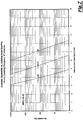
- Fig. 4 the empirical results of the attenuation of the received signal relative to the axial separation of the antennas are shown. Note that the empirical results graphed in Figs. 4 through 8 were utilizing four inch long antennas.
- the attenuation of the received signal relative to the coaxial case has been calculated for operating frequencies of 100 Hz, 1.0 kHz, 10.0 kHz and 100 kHz.
- the axial length of the antennas used for the cases shown is 4 inches.
- the antenna axial spacing is the horizontal distance from the center of one antenna to the center of the second antenna, as will be more fully explained later in the disclosure. As illustrated in Fig.
- the attenuation of the signal propagating in the internal bore of the drill-collar is severe.
- the signal levels drop off by approximately 200 dB per foot as the center-to-center axial spacing of the antennas is increased.
- the most preferred operation of the wireless link is with center-to-center axial spacings of the antennas less than the total length of the antennas. This provides some axial overlap of the two antennas and minimizes signal attenuation.
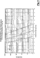
- the amount of power required by the apparatus system 10 to provide good data transmission has also been analyzed. Two cases were analyzed. The first case was the amount of bandwidth provided for a 10 dB signal-to-noise ratio (SNR) as a function of axial antenna spacing. A SNR of 10 dB is typically required for most high-performance synchronous data communication systems. The 10 dB results for two operating frequencies are shown in Figs. 5 and 6 . Note that the antenna axial spacing of the horizontal axis represents the distance from the center of one antenna to the center of the second antenna. As illustrated in the figures, good performance can be achieved with reasonable transmitter power levels and antenna spacings. The two figures also illustrate the effect of the high rate of attenuation inside the drill collar bore. Increasing the transmitter power by a factor of 10 only provides an additional 1 to 2 inches of antenna spacing.
- SNR signal-to-noise ratio
- the second case that has been analyzed is the amount of bandwidth provided for a 30 dB SNR as a function of axial antenna spacing.
- a SNR of 30 dB a much simpler asynchronous data communications systems can be employed for the wireless link.
- Figs. 7 and 8 present the 30 dB results for two operating frequencies.
- increasing the SNR requirements from 10 dB to 30 dB only reduces the required antenna spacing by approximately 1 inch.
- a spacing of 6 inches will provide a signal bandwidth of 1000 Hz with a SNR of 10 dB.
- this spacing is reduced from 6 inches to 4.9 inches at the 1 mW, 1000 Hz bandwidth point (as seen in Fig. 7 ). This is a reduction of only 1.1 inches.
- the wireless system link can be implemented with relatively low power. Power levels on the order of 1 mW will provide adequate performance. Also, for the most preferred embodiment, the axial antenna spacings should be such that there is some overlap of the two antennas.
- the testing also shows that signal attenuation does not increase dramatically with operating frequency.
- the operating frequency of the apparatus can be made as high as 10 kHz or 100 kHz.
- Increasing the operating frequency has the advantage of making the system immune to noise that is mechanically induced by the drilling operation.
- the mechanically induced noise should be virtually eliminated at frequencies above 5 kHz.
- a simple, robust, asynchronous communication system can be used for the apparatus 10 link without compromising the performance of the system.
- the high SNR requirements for the asynchronous link will only reduce the effective range of allowed axial antenna spacings by approximately 1 inch.
- a simple asynchronous system will reduce the complexity and size of the module electronics and also provide a simple user interface.
- the most preferred system for the apparatus is the standard RS-232 serial transmission protocol. This allows the use of a simple UART for the interface to the electronics module.
- FSK frequency shift keying
- OOK on-off keying
- PSK Phase Shift Keying
- MPSK Multi-Phase Shift Keying
- MAPSK Multiple Amplitude Phase Shift Keying
- the length of one or both of the antennas may be extended to decrease the sensitivity of system performance on axial misalignment of the probe and collar antennas.
- Figure 9 illustrates this concept.
- the length of the probe antenna can be made longer than the collar antenna.
- the axial location of the probe within the central bore of the drill collar can vary over a significantly larger interval.
- the coupling between the two antennas will be sufficient to provide good system performance.
- the length of the collar antenna could be made longer than the probe antenna.
- the coupling between the antennas will be adequate for good performance.
- Fig. 9A a schematic illustration of a probe antenna 200 centrally aligned with the collar antenna 202. More specifically, the probe antenna 200 is disposed about the probe 8, and the collar antenna 202 is disposed about the inner portion of the collar 2, as previously noted. As shown, the length of the antenna windings of the probe antenna 200 is longer than the length of the antenna windings of the collar antenna, and wherein the probe antenna 200 is positioned in the collar bore with the center of the antennas aligned.
- Fig. 9B a schematic illustration of the center of the probe antenna being higher than the center of the collar antenna is shown.
- the probe antenna 200 is positioned in the collar bore with the center of the probe antenna 200 higher than the collar antenna 202. It should be noted, however, that in the position shown in Fig. 9B , there is still no axial separation and instead depicts an axial overlap between the probe antenna 200 and the collar antenna 202.
- Fig. 9C a schematic illustration of the center of the probe antenna 200 being lower than the center of the collar antenna 202 is shown. Fig. 9C also depicts the axial overlap.
- Fig. 9D a schematic illustration of the probe antenna being axially separated from the collar antenna 202 by a distance "L".
- Fig. 9D depicts a scenario where there is no axial overlap between the probe antenna 200 and the collar antenna 202.
- the disclosed embodiments allow for greater misalignment of probe antenna 200 relative to the collar antenna 202.
- extending the probe antenna allows for greater misalignment of the two antennas when dealing with problems associated with the varying lengths of collars and probes and the location of the hardware used to position the probe inside the collar bore.
Landscapes
- Physics & Mathematics (AREA)
- Life Sciences & Earth Sciences (AREA)
- Engineering & Computer Science (AREA)
- General Life Sciences & Earth Sciences (AREA)
- Geophysics (AREA)
- Mining & Mineral Resources (AREA)
- Geology (AREA)
- Remote Sensing (AREA)
- General Physics & Mathematics (AREA)
- Environmental & Geological Engineering (AREA)
- Fluid Mechanics (AREA)
- Electromagnetism (AREA)
- Geochemistry & Mineralogy (AREA)
- Arrangements For Transmission Of Measured Signals (AREA)
Description
- This invention relates to an apparatus that provides communication between a probe and a sensor. More particularly, but not by way of limitation, this invention relates to an apparatus and method that provides communication between a probe located in the central bore of a drill collar and sensor electronics located in the drill collar wall.
- In the course of drilling wells, an operator finds it necessary to learn geologic properties of the subterranean zones. Regardless of whether the zones contain hydrocarbons, the knowledge of specific features and characteristics of the various reservoirs is imperative for the economical exploitation of a field. One way to obtain geologic information of the formation is to lower a probe on a wire line. The probe may contain various sensors such as resistivity, gamma ray, gamma density, neutron porosity, pressure, etc. As those of ordinary skill in the art will recognize, the probes may be lowered in open hole situations intermittent of drilling operations, or in post drilling applications where the well contains casing. These type of operations are commonly referred to as well logging.
- Another prior art technique is the use of sensors during actual drilling operations. Two techniques commonly used in the industry are logging while drilling (LWD) and measurement while drilling (MWD) devices. Both the LWD and MWD devices employ sensors that collects specific types of information, and wherein that information is transferred to a down hole processor. The down hole processor in turn transmits the information to the surface. The transmission media may be a cable that electrically connects the down hole processor to a surface processor. Alternatively, the transmission media may be the fluid column in the well, and wherein the down hole device contains a vibrating valve that transmits coded fluid pressure pulses that will be decoded at the surface.
- Typically the MWD sensors are placed in a cylindrical probe that is located in the central bore of the drill collar. Theses sensors are not affected by the steel of the surrounding drill collar and are able to make measurements continuously while drilling. However, some of the LWD sensors and some of the newer generation MWD sensors can be strongly affected by the surrounding drill collar and have to be located in the external wall of the drill collar. Examples of LWD/MWD measurements that are affected by the drill collar are resistivity, annulus pressure, gamma density, and to some extent natural gamma ray. Quite often the drilling operation will make use of both MWD and LWD measurement systems. In these situations there can be sensors located in both the probe positioned in the central bore of the drill collar and sensors located in the external wall of the drill collar. As a result, some form of communication is required between these sensor systems to coordinate the measurement functions and transmit data to the surface.
- Prior art techniques require that the probe located in the central bore of the drill collar and the sensors located in the collar wall contain a wired connection. However, wired connections are very problematic. Therefore, there is a need for a wireless link between the collar sensors and probe.
US 2004/0238166 A1 andUS 4 806 928 A disclose an interrogator and a sensing device attached to a casing in a wellbore with the interrogator and sensing device communicating in a wireless manner.US 2005/016770 A1 relates to a system and method for determining annular pressure while drilling. More specifically, there is a need for an electromagnetic (EM) communication between an LWD/MWD probe located in the internal bore of a drill collar and sensor electronics located in the drill-collar wall. These, and many other needs will be met by the invention herein disclosed. - The present invention is defined in the accompanying claims.
- An apparatus for communicating a sensor to a probe is disclosed. The apparatus includes a sensor means, positioned within a pocket in a tubular string, for collecting information of the characteristic and processing the information, a first modem means for modulating the information from the sensor means into a signal, and a sensor antenna electrically connected to the first modem means for generating an electromagnetic wave. The apparatus further includes a probe antenna, concentrically disposed within the tubular string, for receiving the electromagnetic wave, and, a second modem means for demodulating the electromagnetic wave into the information.
- In one preferred embodiment, the sensor means may measure the following properties: resistivity; gamma ray; or pressure. The sensor means may include a circuit for collecting an analog signal and generating a digital record. In one preferred embodiment, the operating frequency range of the sensor antenna and the probe antenna is between 10,000 hertz and 100,000 hertz. In the most preferred embodiment, the connection between the modem means and the probe means is a universal asynchronous receiver/transmitter (UART) interface, and the protocol of the UART is the
RS 232 standard. Also, in one embodiment, there is some overlap in the axial direction of the probe antenna and the sensor antenna. - In the most preferred embodiment, the probe antenna is disposed about the outer periphery of the probe, and the sensor antenna is disposed about the inner tubular string. The length of one of the antennas is longer than then length of the other antenna so that the electromagnetic coupling between the antennas is less sensitive to axial misalignment of the two antennas. This makes positioning of the probe in the center bore of the collar less problematic. The well bore may contain a fluid column, and wherein the probe drives a fluid valve that transmits fluid pressure pulses indicative of the measured properties.
- A method for communicating a sensor located within a tubing string with a probe concentrically disposed within the tubing string is also disclosed. The method comprises providing the sensor located within the tubing string, generating a reading from the sensor, and transmitting the reading to a first modem means. Next, the reading is converted to a modulated signal, and the modulated signal is directed to a tubing string antenna located within the tubing string, and an electromagnetic signal is generated with the tubing string antenna in response to the reading from the sensor.
- The method includes receiving the propagating wave with a probe antenna located within the probe, and demodulating the electromagnetic wave (signal) within a second modem means to the reading. The reading is transmitted to a probe electronics module located within the probe. In one preferred embodiment, the sensor measures the characteristics of resistivity, gamma ray or pressure. The step of generating the reading from the sensor may include collecting an analog signal within a circuit and generating a digital record from the analog signal.
- In a second embodiment, an apparatus for communicating a sensor with a control unit is disclosed. This apparatus comprises a housing containing the sensor, with the first housing having an opening therein, and a probe, slidably disposed within the opening. The apparatus includes a first circuit means, disposed within the housing, for receiving a reading generated by the sensor and generating an output reading, a first modem means, electrically connected with the first circuit means, for demodulating the output reading, and a housing antenna, electrically connected with the first modem means, for generating a modulated electromagnetic wave.
- The second embodiment further includes a probe antenna, disposed about the probe, for receiving the modulated electromagnetic wave, a second modem means, electrically connected with the probe antenna, for converting the electromagnetic wave to the output reading, and a second circuit means, electrically connected with the second modem means and positioned within the probe, for processing and recording the output reading into a digital record. In the preferred embodiment, the probe antenna can generate modulated electromagnetic waves and wherein the housing antenna can receive the modulated electromagnetic waves. The second circuit means can generate an output command that is received by the second modem means, and wherein the second modem means modulates the output command that is received by the probe antenna for generation of the modulated electromagnetic wave, which in turn will be received by the housing antenna.
- In one preferred embodiment, the probe antenna is disposed about the periphery of the probe, and the probe antenna comprises a non-metallic coil form; an antenna winding about the coil form, and a non-metallic shield covering the antenna winding. Also, the housing antenna may comprise a non-metallic coil form that is adjacent an inner pocket; an antenna winding placed about the non-metallic coil form; and a non-metallic shield covering the antenna winding.
- As noted earlier, since the probe and sensor electronics are located in separate sealed pressure housings, a wired connection between them is problematic. An advantage of the present invention is that it allows bi-directional transfer of data between the probe and sensor electronics without the use of wires. The wireless communication link overcomes the prior art problems and eliminates the complexities of connecting wires between the probe and the collar electronics in the field.
- Another advantage is that the disclosed method and apparatus allows a simple and cleaner field tool make-up, and wherein no wired connections are required to be made in the field. Also, another advantage of the disclosed method is a decreased sensitivity to axial misalignment of the probe inside the collar bore when the axial length of one of the antennas is extended to provide larger tolerance of axial alignment of the two antennas. Yet another advantage is that no pressure feed-thrus are required to route wiring between the probe and the collar.
- A feature of the present invention is that the apparatus uses electromagnetic radiation to establish the communication link. Another feature is that the probe and drill-collar instrumentation are in completely separate pressure containers reducing the risk of flooding both devices should one pressure container develop a leak. Yet another feature is that there are fewer mechanical intrusions into the fluid flowing through the center of the drill collar.
-
-
FIGURE 1 is a perspective block diagram of the most preferred embodiment of the present invention. -
FIGURE 2A is a block diagram of one of the preferred embodiments of the drill collar electronics. -
FIGURE 2B is a block diagram of one of the preferred embodiments of the probe electronics. -
FIGURE 3A is a block diagram of the most preferred embodiment of the drill collar electronics. -
FIGURE 3B is a block diagram of the most preferred embodiment of the probe electronics. -
FIGURE 4 is a graph of signal attenuation as a function of axial antenna spacing. -
FIGURE 5 is a graph of the available bandwidth at a 10,000 Hertz operating frequency for a 10 dB Signal-To-Noise ratio (SNR) as a function of axial antenna spacing for three transmitter power levels. -
FIGURE 6 is a graph of the available bandwidth at a 100,000 Hertz operating frequency for a 10 dB Signal-To-Noise ratio (SNR) as a function of axial antenna spacing for three transmitter power levels. -
FIGURE 7 is a graph of the available bandwidth at a 100,000 Hertz operating frequency for a 30 dB Signal-To-Noise ratio (SNR) as a function of axial antenna spacing for three transmitter power levels. -
FIGURE 8 is a graph of the available bandwidth at a 100,000 Hertz operating frequency for a 30 dB Signal-To-Noise ratio (SNR) as a function of axial antenna spacing for three transmitter power levels. -
FIGURE 9A is a schematic illustration of the probe antenna centrally aligned with the collar antenna. -
FIGURE 9B is a schematic illustration of the center of the probe antenna being higher than the center of the collar antenna. -
FIGURE 9C is a schematic illustration of the center of the probe antenna being lower than the center of the collar antenna. -
FIGURE 9D is a schematic illustration of the probe antenna being axially separated from the collar antenna -
FIGURE 10 is a partial cross-sectional view of the preferred antenna construction embodiment. - Referring now to
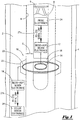
Fig. 1 , a perspective block diagram of the most preferred embodiment of the present invention will now be described. As shown inFig. 1 , atubular member 2, such as a drill collar, is disposed within awell bore 4. Thedrill collar 2 has aninternal diameter portion 6, and wherein theprobe 8, which is generally cylindrical, is slidably disposed within theinternal diameter portion 6. Thedrill collar 2 may be connected to a drill bit used for boring a bore hole. Theprobe 8 may be operatively associated with a MWD tool or LWD tool (not shown). As those of ordinary skill in the art will appreciate, the MWD tool can create a pressure pulse that duplicates a digital code transmission thereby allowing the transmission of down hole data to the surface. MWD and LWD tools are commercially available from Baker Hughes Inc. It should also be noted that theprobe 8 may be connected via a hard wired cable, known in the industry as electric line, and wherein the transmission path of the electrical signals is the electric line. The pressure pulse valve is denoted by thenumeral 9. -
Fig. 1 depicts the apparatus, seen generally at 10, and wherein theapparatus 10 consists of two modem electronic modules and two antennas. More specifically, the firstmodem electronics module 12 and theprobe antenna 14 are located in theprobe 8. Theprobe antenna 14 is located on the outer periphery of theprobe 8, underneath anon-conducting sleeve 16. Thisnon-conductive sleeve 16 protects theprobe antenna 14 from the drilling fluid flowing through theinternal diameter portion 6 of thedrill collar 2. - The
apparatus 10 further includes a secondmodem electronics module 18 and drill collar antenna 20 (sometimes referred to as the tubing antenna 20) located in thedrill collar 2. Thedrill collar antenna 20 is located in apocket 22 on the inside diameter portion of thedrill collar 2. Thispocket 22 is filled with a non-conducting material that covers thedrill collar antenna 20 and protects it from the drilling fluid flowing through the inside of thedrill collar 2. Because thesleeve 16 covering theprobe antenna 14 and the pocket material covering the drill-collar antenna 20 are non-conductive, electromagnetic (EM) signals can pass between the two antennas and allow a wireless data communications link to be established between theprobe electronics 24 and thesensor electronics 26. Theprobe electronics 24 allow for the processing, storage and bidirectional transmission of data with the firstmodem electronics module 12. Thesensor electronics 26 collects information received from the various types of down hole sensors available such as resistivity, gamma ray, pressure, etc., and thesensor electronics 26 further allows for the bidirectional transmission of this data with the secondmodem electronics module 18. - In the most preferred embodiment, the first modem
electronic module 12 and second modemelectronic module 18 of the apparatus-system 10 will use the same electronic design. This allows the same modem module to be used for either position in the down hole tool. The connection between the modem electronic modules and the rest of the down hole tool system will utilize a Universal Asynchronous Receiver Transmitter (UART) interface. Thus, thesensor electronics 26 will employ a UART chip and theprobe electronics 24 will also employ a UART chip. The interface between the electronic modules and the modem modules will employ the RS-232 standard for serial communication, as seen by thelink 27a between theprobe electronics 24 and the firstmodem electronics module 12, as well as the RS-232link 27b between thesensor electronics 26 and the secondmodem electronics module 18. In this configuration, theapparatus 10 operates as a simple modulator-demodulator (modem) transferring the transmit data and the receive data signals of the UART interface across the EM link. The signal levels on the UART interface will be +5V logic levels, allowing the modem modules (namelymodem electronics modules 12, 18) to be wired directly to standard UART that are embedded in most microprocessors. - Attenuation of EM signals propagating in the internal bore of a drill-collar can be extremely high. As a result, and as per the teachings of the present invention, there should be some axial overlap of the
probe antenna 14 and thedrill collar antenna 20. In the most preferred embodiment, theprobe antenna 14 and thedrill collar antenna 20 will be located coaxial with the axial center points of the antennas located in the same plane, as seen inFig. 1 . This configuration reduces the EM signal attenuation and provides the lowest error rate possible for the data transmitted through theapparatus system 10. - Referring now to
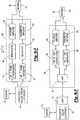
Fig. 2A , a block diagram of one of the preferred embodiments of the drill collar electronics will now be described. It should be noted that like numbers appearing in the various figures refer to like components. More specifically, asensor 32 will collect data such as resistivity of the formation fluids. Thesensor 32 may also collect information on the gamma ray counts of the formation, the pressure of the well bore, and other properties as well understood by those of ordinary skill in the art. Thesensor 32 is physically located within the drill collar. Thesensor 32 may include a circuit means for collecting an analog signal and generating a record. The data collected by thesensor 32 is transmitted to thecollar sensor electronics 34, and wherein thecollar sensor electronics 34 includes a processor for receiving a reading generated by the sensor, processing the data signals from thesensor 32, and generating a digital output. The digital data will then be sent to the modem 36 (sometimes referred to as a transceiver 36). - As seen in
Fig. 2A , the modem means 36 includes abit frame generator 37 that receives the digital data and formats the serial data stream for amodulator 38 that in turn will deliver the signal to thetransmitter amplifier 40. In turn, the analog signal will be delivered to theantenna 42, wherein theantenna 42 is a radio frequency transducer. Theantenna 42 is a coil of wire and the antenna will transmit the electromagnetic waves to a receiving antenna seen inFig. 2B . - Referring now to
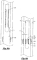
Fig. 10 , a cross-sectional diagram of one of the preferred embodiments of the antenna is illustrated. As per the teachings of the present invention, the antennas are wound on coil forms fabricated with a non-metallic or non-conductive material such as fiberglass or polyetheretherketone (PEEK). As shown inFig. 10 , theprobe 8 is disposed within thedrill collar 2. This view shows thenon-metallic coil form 120 disposed about thedrill collar 2, as well as theantenna windings 122 disposed on the outer periphery of thedrill collar 2. As seen inFig. 10 , thenon-metallic shield 124 covers and shields theantenna windings 122. -
Fig. 10 also shows theprobe antenna windings 126, placed about thenon-metallic coil form 128.Fig. 10 further depicts thenon-metallic shield 130 for covering the antenna winding 126...Winding the wire of the antenna on this type of coil form reduces eddy current losses and improves the efficiency of the antenna by spacing the antenna away from the conductive materials of the collar and probe. The antennas are constructed without the use of soft ferro-magnetic materials like soft iron or ferrite. Soft ferro-magnetic materials are typically used to concentrate the magnetic field through the coil windings and increase the inductive coupling between the two antennas. Eliminating the requirement for ferro-magnetic materials to enhance the inductive coupling between the antennas simplifies the construction of the antennas and also allows a significant gap (such as "G" as seen inFig. 10 ) to be used between the collar and probe antennas. This gap between the two antennas provides a path for the drilling fluids that flow down the center of the collar. - Also, prior art devices that use soft ferro-magnetic materials to direct and concentrate the magnetic field between the two antennas require relatively precise axial alignment of the two coils in order for the device to operate properly. In the most preferred embodiment, the antennas of the present invention are manufactured from copper. -Eliminating the need for these ferro-magnetic materials in this antenna design allows a larger tolerance for alignment of the coils and makes the system more tolerant to axial misalignment of the two antennas.
- Returning to
Fig. 2A , the system herein described is also bidirectional. Hence, theantenna 42 can also receive electromagnetic waves and directed the analog signal to the modem means 36, and in particular to thereceiver amplifier 44. The resulting signal is therefore amplified with thereceiver amplifier 44. The signal is then demodulated and converted to a digital signal in thedemodulator 46. The demodulated signal would then be transmitted to the bit/frame synchronizer 47 which formats the serial data stream and thereafter the digital data stream is transmitted to the collarsensor electronics module 34. The digital signal may be a command to poll thesensor 32, in which case thesensor 32 can take a reading, and wherein thesensor 32 would collect the data and in turn send the data to the collarsensor electronics module 34. The process of generating a corresponding electromagnetic wave withantenna 42 is the same as previously described. - Referring now to
Fig. 2B , a block diagram of the one of the preferred embodiments of the probe electronics, including the probe modem means 48 (sometimes referred to as a transceiver 48), will now be described. Theantenna 50 will receive the electromagnetic wave generated from the antenna 42 (seen inFig. 2A ) and whereinantenna 50 is a radio frequency transducer similar in construction toantenna 42. Returning toFig. 2B , theantenna 50 is electrically connected to the modem means 48, and wherein the modem means 48 is similar in construction to the previously mentioned modem means 36. The modem means 48 includesreceiver amplifier 52 which receives the signal from theantenna 50 and amplifies the analog signal. Thereceiver amplifier 52 in turn delivers the signal to ademodulator 54. The demodulated signal would then be transmitted to the bit/frame synchronizer 55 which formats the serial data stream and thereafter the digital data stream is transmitted to theprobe electronics module 56. Theprobe electronics module 56, which may include a processor for storing and processing the data can then send the data to acontrol unit 58. Thecontrol unit 58 may be located at the surface. Thecontrol unit 58 may communicate with theprobe electronics module 56 via a hard wire (such as a electric line cable) or may transmit pressure pulses via MWD or LWD techniques, as previously described. In the most preferred embodiments, theantenna 50 is a coil of wire as previously described with reference toFig. 10 , which uses a copper wire in the preferred embodiment. - In accordance with the teachings of the present invention, communications may be bidirectional. Hence,
probe electronics module 56 can send a signal to the modem means 48. It should be noted that the operator may institute this transmission via thecontrol unit 58. More specifically, a bit/frame generator 59 of the modem means 48 receives the digital data fromprobe electronics module 56 and formats the serial data stream for themodulator 60 which will modulate the data stream, and wherein the modulated analog signal can then be directed totransmitter amplifier 62 for amplification. The modulated signal data is then sent to theantenna 50 which generates the electromagnetic signal that will be received by theantenna 42 seen inFig. 2A . - Referring now to
Fig. 3A , a block diagram of the most preferred embodiment of the drill collar electronics will now be described. In this embodiment, the sensor means 70 collects information such as a resistivity measurement, gamma ray count, and/or pressure reading, and in turn directs that information to the drill collarsensor electronics module 72. As noted earlier, the drill collarsensor electronics module 72 contains a processor for collecting, storing and processing the information from thesensor 70. The drill collarsensor electronics module 72 further contains aUART 74, and wherein theUART 74 converts the parallel digital information to a serial data stream. - The serial data stream is directed to the first modem means 76, and wherein the first modem means 76 is also sometimes referred to as
transceiver 76. The first modem means 76 contains theUART 78 that receives the digital data stream fromUART 74 based on the RS-232 standard protocol which in turn directs the signal to themodulator 80 and wherein themodulator 80 can be either a frequency shift keying modulating scheme or an on-off keying scheme as understood by those of ordinary skill in the art. The modulated signal is then directed to thetransmitter amplifier 82 which amplifies the modulated signal for transmission by theantenna 84. Theantenna 84 is of similar construction as the antennas previously discussed which generates an electromagnetic wave signal representative of the information collected by thesensor 70. - According to the teachings of the present invention, the apparatus is bidirectional. Hence, it is possible that the
antenna 84 receive propagating electromagnetic signals and wherein the received signals are directed to thereceiver amplifier 86 which in turn amplifies and directs the analog signal to thedemodulator 88. The received electromagnetic signal may be a command for the sensor to take sample readings. Thedemodulator 88 can use either the frequency shift keying method or the on-off keying method, depending on the modulating scheme of the transmitter, as previously noted. The demodulated signal is then directed to theUART 78 for serial data transmission to theUART 74 on the collarsensor electronics module 72 based on the RS-232 standard protocol. The processor can then communicate the command for thesensor 70 to obtain a reading. The reading can then be taken and wherein the reading can then be sent to the probe as previously described. - Referring now to
Fig. 3B , a block diagram of the most preferred embodiment of the probe electronics will now be described. As noted in the discussion ofFig. 3A , theantenna 84 will generate an electromagnetic signal, and wherein that EM signal will be picked up by theantenna 90. Theantenna 90 is of similar construction of the antennas previously discussed. The signal will in turn be directed to the modem means 91 (also sometimes referred to as a transceiver 91). More specifically, the signal is directed to thereceiver amplifier 92, and wherein thereceiver amplifier 92 will then amplify and direct the analog signal to thedemodulator 94. Thedemodulator 94 can be either the frequency shift keying modulating scheme or the on-off keying scheme, depending on the transmitting modulating scheme. Thedemodulator 94 will then direct the signal to theUART 96. A hard wired connection will exist between the modem means 91 and theprobe electronics module 98. More specifically, theprobe electronics module 98 contains theUART 100 that receives the digital serial communication from theUART chip 96 and wherein theRS 232 standard is used. A processor is contained within theprobe electronics module 98 and theUART 100 can convert the serial data stream to a parallel data stream for the processing by the processor. Theprobe electronics module 98 can communicate with thecontrol unit 102, and wherein the communication path may be a hardwired connection or may be a pressure pulse telemetry type of system, as previously noted. - In accordance with the teachings of this invention, the system is bidirectional. Hence, an operator can generate a signal from the
control unit 102, which will in turn be sent to theprobe electronics module 98. TheUART 100 will then serially transmit the serial data stream to the modem means 91. More specifically, the serial data stream will be received by theUART 96 which in turn will direct the signal to themodulator 104. Themodulator 104 can employ either frequency shift keying modulating or an on-off keying. The modulated signal will then be directed to thetransmitter amplifier 106 for amplification. The analog signal can then be transmitted to theantenna 90 and wherein theantenna 90 will generate the EM signal as previously described, which in turn will be received by theantenna 84. - Referring now to
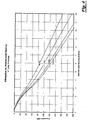
Fig. 4 , the empirical results of the attenuation of the received signal relative to the axial separation of the antennas are shown. Note that the empirical results graphed inFigs. 4 through 8 were utilizing four inch long antennas. InFig. 4 , the attenuation of the received signal relative to the coaxial case has been calculated for operating frequencies of 100 Hz, 1.0 kHz, 10.0 kHz and 100 kHz. The axial length of the antennas used for the cases shown is 4 inches. The antenna axial spacing is the horizontal distance from the center of one antenna to the center of the second antenna, as will be more fully explained later in the disclosure. As illustrated inFig. 4 , the attenuation of the signal propagating in the internal bore of the drill-collar is severe. The signal levels drop off by approximately 200 dB per foot as the center-to-center axial spacing of the antennas is increased. As a result, the most preferred operation of the wireless link is with center-to-center axial spacings of the antennas less than the total length of the antennas. This provides some axial overlap of the two antennas and minimizes signal attenuation. - The amount of power required by the
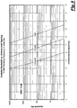
apparatus system 10 to provide good data transmission has also been analyzed. Two cases were analyzed. The first case was the amount of bandwidth provided for a 10 dB signal-to-noise ratio (SNR) as a function of axial antenna spacing. A SNR of 10 dB is typically required for most high-performance synchronous data communication systems. The 10 dB results for two operating frequencies are shown inFigs. 5 and6 . Note that the antenna axial spacing of the horizontal axis represents the distance from the center of one antenna to the center of the second antenna. As illustrated in the figures, good performance can be achieved with reasonable transmitter power levels and antenna spacings. The two figures also illustrate the effect of the high rate of attenuation inside the drill collar bore. Increasing the transmitter power by a factor of 10 only provides an additional 1 to 2 inches of antenna spacing. - With reference to
Figs. 7 and8 , the second case that has been analyzed is the amount of bandwidth provided for a 30 dB SNR as a function of axial antenna spacing. With a SNR of 30 dB, a much simpler asynchronous data communications systems can be employed for the wireless link.Figs. 7 and8 present the 30 dB results for two operating frequencies. As expected, increasing the SNR requirements from 10 dB to 30 dB only reduces the required antenna spacing by approximately 1 inch. Empirically, it has been shown that using a 1 mW transmitter operating at 10 kHz, a spacing of 6 inches will provide a signal bandwidth of 1000 Hz with a SNR of 10 dB. For a 30 dB SNR, this spacing is reduced from 6 inches to 4.9 inches at the 1 mW, 1000 Hz bandwidth point (as seen inFig. 7 ). This is a reduction of only 1.1 inches. - Based on the results of the test, it has been found that the wireless system link can be implemented with relatively low power. Power levels on the order of 1 mW will provide adequate performance. Also, for the most preferred embodiment, the axial antenna spacings should be such that there is some overlap of the two antennas.
- The testing also shows that signal attenuation does not increase dramatically with operating frequency. As a result, the operating frequency of the apparatus can be made as high as 10 kHz or 100 kHz. Increasing the operating frequency has the advantage of making the system immune to noise that is mechanically induced by the drilling operation. The mechanically induced noise should be virtually eliminated at frequencies above 5 kHz.
- A simple, robust, asynchronous communication system can be used for the
apparatus 10 link without compromising the performance of the system. The high SNR requirements for the asynchronous link will only reduce the effective range of allowed axial antenna spacings by approximately 1 inch. A simple asynchronous system will reduce the complexity and size of the module electronics and also provide a simple user interface. The most preferred system for the apparatus is the standard RS-232 serial transmission protocol. This allows the use of a simple UART for the interface to the electronics module. - In addition to allowing the use of a simple asynchronous communication system, providing a high SNR also allows the use of simplified modulation schemes. Although any of the standard modulation schemes used by communication systems can be used in the system, simple modulation schemes such as frequency shift keying (FSK) or on-off keying (OOK) can be employed for the disclosed modem. These modulations schemes are less complicated to implement than the higher performance modulation schemes such as Phase Shift Keying (PSK), Multi-Phase Shift Keying (MPSK), Multiple Amplitude Phase Shift Keying (MAPSK), etc. and can offer similar performance with a relatively small decrease in axial antenna separation without increasing the required transmitter power.
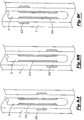
- In applications where the axial placement of the probe inside the drill collar bore can vary with some uncertainty, the length of one or both of the antennas may be extended to decrease the sensitivity of system performance on axial misalignment of the probe and collar antennas.
Figure 9 illustrates this concept. As shown in the figure, the length of the probe antenna can be made longer than the collar antenna. In this configuration, the axial location of the probe within the central bore of the drill collar can vary over a significantly larger interval. As long as there is some overlap of the two antennas, the coupling between the two antennas will be sufficient to provide good system performance. In a similar manner, the length of the collar antenna could be made longer than the probe antenna. Just as in the case illustrated inFig. 9 , as long as there is some overlap between the collar and probe antennas the coupling between the antennas will be adequate for good performance. - Referring now to
Fig. 9A , a schematic illustration of aprobe antenna 200 centrally aligned with thecollar antenna 202. More specifically, theprobe antenna 200 is disposed about theprobe 8, and thecollar antenna 202 is disposed about the inner portion of thecollar 2, as previously noted. As shown, the length of the antenna windings of theprobe antenna 200 is longer than the length of the antenna windings of the collar antenna, and wherein theprobe antenna 200 is positioned in the collar bore with the center of the antennas aligned. - In
Fig. 9B ,a schematic illustration of the center of the probe antenna being higher than the center of the collar antenna is shown. In other words, theprobe antenna 200 is positioned in the collar bore with the center of theprobe antenna 200 higher than thecollar antenna 202. It should be noted, however, that in the position shown inFig. 9B , there is still no axial separation and instead depicts an axial overlap between theprobe antenna 200 and thecollar antenna 202. Referring now toFig. 9C , a schematic illustration of the center of theprobe antenna 200 being lower than the center of thecollar antenna 202 is shown.Fig. 9C also depicts the axial overlap. InFig. 9D , a schematic illustration of the probe antenna being axially separated from thecollar antenna 202 by a distance "L".Fig. 9D depicts a scenario where there is no axial overlap between theprobe antenna 200 and thecollar antenna 202. Hence, as shown inFig. 9D , as the distance "L" increases, the attenuation of the signal increases. However, in accordance with the teachings of the present invention, by having an extended probe antenna winding (such as shown inFig. 9A ,), the disclosed embodiments allow for greater misalignment ofprobe antenna 200 relative to thecollar antenna 202. In other words, extending the probe antenna allows for greater misalignment of the two antennas when dealing with problems associated with the varying lengths of collars and probes and the location of the hardware used to position the probe inside the collar bore.
Claims (23)
- An apparatus for wirelessly communicating characteristics of a down hole environment in a tubular string (2), with the tubular string being concentrically positioned within a well bore (4), the apparatus comprising:a sensor means (32), positioned within a pocket (22) in the tubular string (2), for collecting information of the characteristic and processing the information;a sensor electronics module (26) electrically connected to said sensor means (32);a first modem means (18) for modulating the information from the sensor module (26);a sensor antenna coil winding (20, 122), electrically connected to said first modem means (18), for generating a modulated electromagnetic wave; anda probe (8) to be concentrically positioned within the tubular string (2);a probe antenna coil winding (14, 126), disposed within the probe (8), for receiving the modulated electromagnetic wave and generating an output, the probe antenna coil winding (14, 126) being disposed about the outer periphery of the probe (8) so that a gap (G) is formed between the sensor antenna coil winding (20, 122) and the probe antenna coil winding (14, 126) providing a path for drilling fluids;a second modem means (12) for demodulating the electromagnetic wave received from said sensor means;wherein the sensor antenna coil winding (122) is disposed about the tubular string (2); and characterised in thatthe probe antenna coil winding (126) has a first axial length and the sensor antenna coil winding (122) has a second axial length, wherein the first axial length of the probe antenna coil winding (126) is different from the second axial length of the sensor antenna coil winding (122) to reduce the sensitivity to axial misalignment of the two antenna coil windings (122, 126).
- The apparatus of claim 1 further comprising a probe electronics module (24) electrically connected to said second modem means (12).
- The apparatus of claim 2 wherein said sensor means includes a circuit means for collecting an analog signal and generating a record.
- The apparatus of claim 2 wherein an operating frequency range of said sensor antenna coil winding (122) and said probe antenna coil winding (126) is between 1,000 Hertz and 100,000 Hertz.
- The apparatus of claim 4 wherein the connection between the first modem means (18) and the sensor electronics module (26) is a universal asynchronous receiver/transmitter (UART) interface.
- The apparatus of claim 5 wherein the protocol of the UART interface is the RS 232 standard.
- The apparatus of claim 6 wherein there is some axial overlap of the probe antenna coil winding (126) and the sensor antenna coil winding (122).
- The apparatus of claim 7 wherein the probe (8) is a cylindrical member having an outer periphery and the probe antenna coil winding (126) is concentrically disposed about the outer periphery of the probe (8).
- The apparatus of claim 1 wherein the first axial length of the probe antenna coil winding (126) is longer than the second axial length of the sensor antenna coil winding (122).
- The apparatus of claim 1 wherein the second axial length of the sensor antenna coil winding (122) is longer than the first axial length of the probe antenna coil winding (126).
- The apparatus of claim 1 wherein the tubular string (2) has contained therein a fluid column, and wherein the probe electronics module (24) driving a fluid valve that transmits fluid pressure pulses indicative of the collecting information from the sensor means.
- The apparatus of claim 1 wherein the probe antenna coil winding (126) is disposed about an outer periphery of the probe (8) and wherein the probe antenna coil winding (126) comprises:
a non-metallic coil form (128); the probe antenna coil winding (126) wrapped about said coil form (128); and a non-metallic shield (128) covering said probe antenna coil winding (126). - The apparatus of claim 12 wherein the sensor antenna coil winding (122) is disposed about an inner pocket (22) within the tubing string (2), and wherein the sensor antenna coil winding (122) comprises: a non-metallic coil form that is adjacent the inner pocket (22); the sensor antenna coil winding (126) about said non-metallic coil form; and, a non-metallic shield covering said antenna winding.
- The apparatus of claim 13 wherein an operating frequency range of said sensor antenna coil winding (122) and said probe antenna coil winding (126) is between 10,000 Hertz and 100,000 Hertz, and a transmitter power range of the sensor antenna coil winding (122) between 1 Watt and 0.001 Watt.
- A method for communicating a sensor located within a tubing string (2) with a probe (8) concentrically disposed within the tubing string (2), the method comprising:providing the sensor within the tubing string (2);generating a reading from the sensor;transmitting the reading to a first modem means (18);modulating the reading onto a carrier wave to produce a modulated signal;directing the modulated signal to a tubing string antenna coil winding (122) located within the tubing string (2);generating an electromagnetic signal with the tubing string antenna coil winding (122) in response to the reading from said sensor;receiving the electromagnetic signal with a probe antenna coil winding (126) located within the probe (8), the probe antenna coil winding (126) being disposed about the outer periphery of the probe (8) so that a gap (G) is formed between the sensor antenna coil winding (122) and the probe antenna coil winding (126) providing a path for drilling fluids; anddemodulating the electromagnetic signal within a second modem means (12) in the probe (8) to the reading;transmitting the reading to a probe electronics module (24) located with the probe (8);wherein the probe antenna coil winding (126) is disposed about the outer periphery of the probe (8) and the tubing string antenna coil winding (122) is disposed about an inner portion of the tubing string (2); and characterised in thatthe probe antenna coil winding (126) has a first length and the tubing string antenna coil winding (122) has a second length;wherein the axial length of the probe antenna coil winding (126) is different from the axial length of the tubing string antenna coil winding (122) to reduce the sensitivity to axial misalignment of the two antenna coil windings (122, 126).
- The method of claim 15 wherein said sensor is selected from the group of resistivity sensors, gamma ray sensors, or pressure sensors.
- The method of claim 16 wherein the step of generating the reading from the sensor includes collecting an analog signal within a circuit and generating a record from said analog signal.
- The method of claim 16 wherein an operating frequency range of said tubing string antenna coil winding (122) and said probe antenna coil winding (126) is between 10,000 Hertz and 100,000 Hertz.
- The method of claim 18 wherein an electrical connection between the second modem means (12) and the probe electronics module (24) is a universal asynchronous receiver/transmitter (UART).
- The method of claim 19 wherein the protocol of the UART interface is the RS 232 standard.
- The method of claim 15 wherein an axial overlap between the probe antenna coil winding (126) and the tubing string antenna coil winding (122) is formed.
- The method of claim 15 wherein the axial length of the probe antenna coil winding (126) is longer than the axial length of the tubing string antenna coil winding (122).
- The method of claim 15 wherein an axial length of the tubing string antenna coil winding (122) is longer than an axial length of the probe antenna coil winding (126).
Applications Claiming Priority (2)
| Application Number | Priority Date | Filing Date | Title |
|---|---|---|---|
| US11/159,793 US7411517B2 (en) | 2005-06-23 | 2005-06-23 | Apparatus and method for providing communication between a probe and a sensor |
| PCT/US2006/023717 WO2007001946A2 (en) | 2005-06-23 | 2006-06-20 | Apparatus and method for providing communication between a probe and a sensor |
Publications (4)
| Publication Number | Publication Date |
|---|---|
| EP1896873A2 EP1896873A2 (en) | 2008-03-12 |
| EP1896873A4 EP1896873A4 (en) | 2017-08-09 |
| EP1896873B1 true EP1896873B1 (en) | 2021-02-17 |
| EP1896873B8 EP1896873B8 (en) | 2021-03-31 |
Family
ID=37566662
Family Applications (1)
| Application Number | Title | Priority Date | Filing Date |
|---|---|---|---|
| EP06773485.5A Active EP1896873B8 (en) | 2005-06-23 | 2006-06-20 | Apparatus and method for providing communication between a probe and a sensor |
Country Status (6)
| Country | Link |
|---|---|
| US (2) | US7411517B2 (en) |
| EP (1) | EP1896873B8 (en) |
| CN (1) | CN101208618B (en) |
| CA (1) | CA2609483C (en) |
| HK (1) | HK1119251A1 (en) |
| WO (1) | WO2007001946A2 (en) |
Families Citing this family (60)
| Publication number | Priority date | Publication date | Assignee | Title |
|---|---|---|---|---|
| US20070092022A1 (en) * | 2005-10-26 | 2007-04-26 | Broadcom Corporation | Integrated frequency shift-keying FSK transceiver |
| US8000730B2 (en) * | 2006-07-07 | 2011-08-16 | Wisconsin Alumni Research Foundation | Method and system for improving performance in a sparse multi-path environment using reconfigurable arrays |
| US20080031165A1 (en) * | 2006-08-07 | 2008-02-07 | Fenghua Shen | RS-232 data through a half duplex differential link |
| AU2008272907B2 (en) * | 2007-07-03 | 2011-03-10 | Shell Internationale Research Maatschappij B.V. | Down-hole transmitter system, method of inducing a transient electromagnetic field in an earth formation, method of obtaining a transient electromagnetic response signal, and method of producing a hydrocarbon fluid |
| GB0718956D0 (en) * | 2007-09-28 | 2007-11-07 | Qinetiq Ltd | Wireless communication system |
| US8242436B2 (en) * | 2010-11-30 | 2012-08-14 | Sondex Limited | Neutron porosity logging tool using microstructured neutron detectors |
| US9179843B2 (en) | 2011-04-21 | 2015-11-10 | Hassan Ghaderi MOGHADDAM | Method and system for optically evaluating proximity to the inferior alveolar nerve in situ |
| US20140084946A1 (en) * | 2012-09-24 | 2014-03-27 | Schlumberger Technology Corporation | System And Method For Wireless Power And Data Transmission In A Rotary Steerable System |
| DE102012110336A1 (en) | 2012-10-29 | 2014-04-30 | Thyssenkrupp Resource Technologies Gmbh | roll crusher |
| RU2616551C2 (en) * | 2012-11-27 | 2017-04-17 | Хэллибертон Энерджи Сервисиз, Инк. | Software applications for data transmission |
| US9759062B2 (en) | 2012-12-19 | 2017-09-12 | Exxonmobil Upstream Research Company | Telemetry system for wireless electro-acoustical transmission of data along a wellbore |
| US10480308B2 (en) | 2012-12-19 | 2019-11-19 | Exxonmobil Upstream Research Company | Apparatus and method for monitoring fluid flow in a wellbore using acoustic signals |
| WO2014100266A1 (en) | 2012-12-19 | 2014-06-26 | Exxonmobil Upstream Research Company | Apparatus and method for relieving annular pressure in a wellbore using a wireless sensor network |
| WO2014100275A1 (en) | 2012-12-19 | 2014-06-26 | Exxonmobil Upstream Research Company | Wired and wireless downhole telemetry using a logging tool |
| WO2014146207A1 (en) | 2013-03-21 | 2014-09-25 | Altan Technologies Inc. | Microwave communication system for downhole drilling |
| CA2913703C (en) | 2013-05-31 | 2020-09-29 | Evolution Engineering Inc. | Downhole pocket electronics |
| US9268053B2 (en) * | 2013-06-12 | 2016-02-23 | Well Resolutions Technology | Apparatus and methods for making azimuthal resistivity measurements |
| CN105518245B (en) | 2013-09-05 | 2018-08-07 | 开拓工程股份有限公司 | Across the electrical isolation gap transmission data in drill string |
| WO2015042291A1 (en) * | 2013-09-20 | 2015-03-26 | Halliburton Energy Services, Inc. | Quasioptical waveguides and systems |
| WO2015080754A1 (en) | 2013-11-26 | 2015-06-04 | Exxonmobil Upstream Research Company | Remotely actuated screenout relief valves and systems and methods including the same |
| US9763216B2 (en) | 2014-08-08 | 2017-09-12 | Wisconsin Alumni Research Foundation | Radiator localization |
| WO2016039900A1 (en) | 2014-09-12 | 2016-03-17 | Exxonmobil Upstream Research Comapny | Discrete wellbore devices, hydrocarbon wells including a downhole communication network and the discrete wellbore devices and systems and methods including the same |
| WO2016048457A1 (en) | 2014-09-26 | 2016-03-31 | Exxonmobil Upstream Research Company | Systems and methods for monitoring a condition of a tubular configured to convey a hydrocarbon fluid |
| US20160180804A1 (en) * | 2014-12-23 | 2016-06-23 | Intel Corporation | Refresh rate control using sink requests |
| US9863222B2 (en) | 2015-01-19 | 2018-01-09 | Exxonmobil Upstream Research Company | System and method for monitoring fluid flow in a wellbore using acoustic telemetry |
| US10408047B2 (en) | 2015-01-26 | 2019-09-10 | Exxonmobil Upstream Research Company | Real-time well surveillance using a wireless network and an in-wellbore tool |
| AU2015385796B2 (en) * | 2015-03-11 | 2018-10-18 | Halliburton Energy Services, Inc. | Downhole wireless communication using surface waves |
| BR112017016444A2 (en) | 2015-03-11 | 2018-04-10 | Halliburton Energy Services Inc | assembly, system and antenna for indoor communication using surface waves. |
| BR112017015953A2 (en) * | 2015-03-11 | 2018-03-20 | Halliburton Energy Services, Inc. | communication system and method |
| US10047602B2 (en) * | 2015-09-09 | 2018-08-14 | Aps Technology, Inc. | Antennas for a drilling system and method of making same |
| US20180348394A1 (en) * | 2015-12-07 | 2018-12-06 | Halliburton Energy Services, Inc. | Modular tool having combined em logging and telemetry |
| US10697287B2 (en) | 2016-08-30 | 2020-06-30 | Exxonmobil Upstream Research Company | Plunger lift monitoring via a downhole wireless network field |
| US10167716B2 (en) | 2016-08-30 | 2019-01-01 | Exxonmobil Upstream Research Company | Methods of acoustically communicating and wells that utilize the methods |
| US10526888B2 (en) | 2016-08-30 | 2020-01-07 | Exxonmobil Upstream Research Company | Downhole multiphase flow sensing methods |
| US11828172B2 (en) | 2016-08-30 | 2023-11-28 | ExxonMobil Technology and Engineering Company | Communication networks, relay nodes for communication networks, and methods of transmitting data among a plurality of relay nodes |
| US10465505B2 (en) | 2016-08-30 | 2019-11-05 | Exxonmobil Upstream Research Company | Reservoir formation characterization using a downhole wireless network |
| US10190410B2 (en) | 2016-08-30 | 2019-01-29 | Exxonmobil Upstream Research Company | Methods of acoustically communicating and wells that utilize the methods |
| US10344583B2 (en) * | 2016-08-30 | 2019-07-09 | Exxonmobil Upstream Research Company | Acoustic housing for tubulars |
| US10590759B2 (en) | 2016-08-30 | 2020-03-17 | Exxonmobil Upstream Research Company | Zonal isolation devices including sensing and wireless telemetry and methods of utilizing the same |
| US10415376B2 (en) | 2016-08-30 | 2019-09-17 | Exxonmobil Upstream Research Company | Dual transducer communications node for downhole acoustic wireless networks and method employing same |
| US10364669B2 (en) | 2016-08-30 | 2019-07-30 | Exxonmobil Upstream Research Company | Methods of acoustically communicating and wells that utilize the methods |
| US20190004208A1 (en) * | 2017-07-03 | 2019-01-03 | Wolverine Oilfield Technologies | Short distance electromagnetic communication for instruments in electrically conductive housings |
| US10837276B2 (en) | 2017-10-13 | 2020-11-17 | Exxonmobil Upstream Research Company | Method and system for performing wireless ultrasonic communications along a drilling string |
| WO2019074654A2 (en) | 2017-10-13 | 2019-04-18 | Exxonmobil Upstream Research Company | Method and system for performing hydrocarbon operations with mixed communication networks |
| US10697288B2 (en) | 2017-10-13 | 2020-06-30 | Exxonmobil Upstream Research Company | Dual transducer communications node including piezo pre-tensioning for acoustic wireless networks and method employing same |
| US10883363B2 (en) | 2017-10-13 | 2021-01-05 | Exxonmobil Upstream Research Company | Method and system for performing communications using aliasing |
| AU2018347467B2 (en) | 2017-10-13 | 2021-06-17 | Exxonmobil Upstream Research Company | Method and system for performing operations with communications |
| CN111201755B (en) | 2017-10-13 | 2022-11-15 | 埃克森美孚上游研究公司 | Method and system for performing operations using communication |
| US10690794B2 (en) | 2017-11-17 | 2020-06-23 | Exxonmobil Upstream Research Company | Method and system for performing operations using communications for a hydrocarbon system |
| CN111247310B (en) | 2017-11-17 | 2023-09-15 | 埃克森美孚技术与工程公司 | Method and system for performing wireless ultrasound communication along a tubular member |
| US12000273B2 (en) | 2017-11-17 | 2024-06-04 | ExxonMobil Technology and Engineering Company | Method and system for performing hydrocarbon operations using communications associated with completions |
| US10844708B2 (en) | 2017-12-20 | 2020-11-24 | Exxonmobil Upstream Research Company | Energy efficient method of retrieving wireless networked sensor data |
| CN111542679A (en) | 2017-12-29 | 2020-08-14 | 埃克森美孚上游研究公司 | Method and system for monitoring and optimizing reservoir stimulation operations |
| US11156081B2 (en) | 2017-12-29 | 2021-10-26 | Exxonmobil Upstream Research Company | Methods and systems for operating and maintaining a downhole wireless network |
| WO2019156966A1 (en) | 2018-02-08 | 2019-08-15 | Exxonmobil Upstream Research Company | Methods of network peer identification and self-organization using unique tonal signatures and wells that use the methods |
| US11268378B2 (en) | 2018-02-09 | 2022-03-08 | Exxonmobil Upstream Research Company | Downhole wireless communication node and sensor/tools interface |
| NO344782B1 (en) * | 2018-02-14 | 2020-04-27 | Well Id As | Downhole measurement tool assembly for measuring and storing at least one quantity in a wellbore and for wireless surface readout |
| US11952886B2 (en) | 2018-12-19 | 2024-04-09 | ExxonMobil Technology and Engineering Company | Method and system for monitoring sand production through acoustic wireless sensor network |
| US11293280B2 (en) | 2018-12-19 | 2022-04-05 | Exxonmobil Upstream Research Company | Method and system for monitoring post-stimulation operations through acoustic wireless sensor network |
| CN112259275B (en) * | 2020-10-19 | 2022-02-11 | 中国核动力研究设计院 | Communication system and communication method under electromagnetic shielding environment |
Family Cites Families (15)
| Publication number | Priority date | Publication date | Assignee | Title |
|---|---|---|---|---|
| US2370818A (en) * | 1942-07-30 | 1945-03-06 | Stanolind Oil & Gas Co | Well measurement |
| US3727616A (en) * | 1971-06-15 | 1973-04-17 | Gen Dynamics Corp | Electronic system for the stimulation of biological systems |
| US4539992A (en) * | 1978-12-22 | 1985-09-10 | Intermedics, Inc. | Method and apparatus for communicating with implanted body function stimulator |
| US4806928A (en) * | 1987-07-16 | 1989-02-21 | Schlumberger Technology Corporation | Apparatus for electromagnetically coupling power and data signals between well bore apparatus and the surface |
| US4901069A (en) * | 1987-07-16 | 1990-02-13 | Schlumberger Technology Corporation | Apparatus for electromagnetically coupling power and data signals between a first unit and a second unit and in particular between well bore apparatus and the surface |
| US5050675A (en) * | 1989-12-20 | 1991-09-24 | Schlumberger Technology Corporation | Perforating and testing apparatus including a microprocessor implemented control system responsive to an output from an inductive coupler or other input stimulus |
| US5241961A (en) * | 1990-07-13 | 1993-09-07 | Cook Pacemaker Corporation | Synchronous telemetry receiver and receiving method for an implantable medical device |
| US5455573A (en) * | 1994-04-22 | 1995-10-03 | Panex Corporation | Inductive coupler for well tools |
| US6693553B1 (en) * | 1997-06-02 | 2004-02-17 | Schlumberger Technology Corporation | Reservoir management system and method |
| US6392561B1 (en) * | 1998-12-18 | 2002-05-21 | Dresser Industries, Inc. | Short hop telemetry system and method |
| US6443228B1 (en) * | 1999-05-28 | 2002-09-03 | Baker Hughes Incorporated | Method of utilizing flowable devices in wellbores |
| GB2374099B (en) * | 1999-10-13 | 2004-04-21 | Baker Hughes Inc | Apparatus for transferring electrical energy between rotating and non-rotating members of downhole tools |
| US7168487B2 (en) | 2003-06-02 | 2007-01-30 | Schlumberger Technology Corporation | Methods, apparatus, and systems for obtaining formation information utilizing sensors attached to a casing in a wellbore |
| US7178607B2 (en) | 2003-07-25 | 2007-02-20 | Schlumberger Technology Corporation | While drilling system and method |
| US7046164B2 (en) * | 2004-02-24 | 2006-05-16 | Halliburton Energy Services, Inc. | Method and system for well telemetry |
-
2005
- 2005-06-23 US US11/159,793 patent/US7411517B2/en active Active
-
2006
- 2006-06-20 EP EP06773485.5A patent/EP1896873B8/en active Active
- 2006-06-20 CN CN200680022844XA patent/CN101208618B/en not_active Expired - Fee Related
- 2006-06-20 WO PCT/US2006/023717 patent/WO2007001946A2/en active Application Filing
- 2006-06-20 CA CA2609483A patent/CA2609483C/en active Active
-
2008
- 2008-07-31 US US12/221,243 patent/US20090021392A1/en not_active Abandoned
- 2008-08-18 HK HK08109151.8A patent/HK1119251A1/en not_active IP Right Cessation
Non-Patent Citations (1)
| Title |
|---|
| None * |
Also Published As
| Publication number | Publication date |
|---|---|
| CN101208618B (en) | 2011-11-23 |
| US20060290529A1 (en) | 2006-12-28 |
| EP1896873A4 (en) | 2017-08-09 |
| WO2007001946A2 (en) | 2007-01-04 |
| CA2609483C (en) | 2014-04-15 |
| EP1896873B8 (en) | 2021-03-31 |
| US20090021392A1 (en) | 2009-01-22 |
| WO2007001946A3 (en) | 2007-06-21 |
| US7411517B2 (en) | 2008-08-12 |
| CA2609483A1 (en) | 2007-01-04 |
| HK1119251A1 (en) | 2009-02-27 |
| EP1896873A2 (en) | 2008-03-12 |
| CN101208618A (en) | 2008-06-25 |
| WO2007001946A9 (en) | 2007-03-08 |
Similar Documents
| Publication | Publication Date | Title |
|---|---|---|
| EP1896873B1 (en) | Apparatus and method for providing communication between a probe and a sensor | |
| US6018501A (en) | Subsea repeater and method for use of the same | |
| US9477008B2 (en) | Method and system of transmitting acoustic signals from a wellbore | |
| US4578675A (en) | Apparatus and method for logging wells while drilling | |
| US6177882B1 (en) | Electromagnetic-to-acoustic and acoustic-to-electromagnetic repeaters and methods for use of same | |
| US6144316A (en) | Electromagnetic and acoustic repeater and method for use of same | |
| US4630243A (en) | Apparatus and method for logging wells while drilling | |
| EP0911484B1 (en) | Electromagnetic signal repeater and method for use of same | |
| EP0913555B1 (en) | Electromagnetic signal pickup device | |
| EP0273379A2 (en) | Well data transmission system using a magnetic drill string | |
| AU2000265796A1 (en) | Apparatus and method for telemetry | |
| US20180348394A1 (en) | Modular tool having combined em logging and telemetry | |
| GB2346509A (en) | Borehole communication system | |
| EP1276968B1 (en) | Logging sondes for use in boreholes | |
| EP3485142B1 (en) | System for cableless bidirectional data transmission in a well for the extraction of formation fluids |
Legal Events
| Date | Code | Title | Description |
|---|---|---|---|
| PUAI | Public reference made under article 153(3) epc to a published international application that has entered the european phase |
Free format text: ORIGINAL CODE: 0009012 |
|
| 17P | Request for examination filed |
Effective date: 20080123 |
|
| AK | Designated contracting states |
Kind code of ref document: A2 Designated state(s): AT BE BG CH CY CZ DE DK EE ES FI FR GB GR HU IE IS IT LI LT LU LV MC NL PL PT RO SE SI SK TR |
|
| DAX | Request for extension of the european patent (deleted) | ||
| DAX | Request for extension of the european patent (deleted) | ||
| RAP1 | Party data changed (applicant data changed or rights of an application transferred) |
Owner name: SONDEX LIMITED |
|
| RIN1 | Information on inventor provided before grant (corrected) |
Inventor name: SONDEX LIMITED |
|
| REG | Reference to a national code |
Ref country code: DE Ref legal event code: R079 Ref document number: 602006059930 Country of ref document: DE Free format text: PREVIOUS MAIN CLASS: G01V0003000000 Ipc: G01V0011000000 |
|
| A4 | Supplementary search report drawn up and despatched |
Effective date: 20170710 |
|
| RIC1 | Information provided on ipc code assigned before grant |
Ipc: E21B 47/12 20120101ALI20170704BHEP Ipc: G01V 11/00 20060101AFI20170704BHEP |
|
| STAA | Information on the status of an ep patent application or granted ep patent |
Free format text: STATUS: EXAMINATION IS IN PROGRESS |
|
| 17Q | First examination report despatched |
Effective date: 20180326 |
|
| GRAJ | Information related to disapproval of communication of intention to grant by the applicant or resumption of examination proceedings by the epo deleted |
Free format text: ORIGINAL CODE: EPIDOSDIGR1 |
|
| GRAP | Despatch of communication of intention to grant a patent |
Free format text: ORIGINAL CODE: EPIDOSNIGR1 |
|
| GRAP | Despatch of communication of intention to grant a patent |
Free format text: ORIGINAL CODE: EPIDOSNIGR1 |
|
| STAA | Information on the status of an ep patent application or granted ep patent |
Free format text: STATUS: GRANT OF PATENT IS INTENDED |
|
| INTG | Intention to grant announced |
Effective date: 20200120 |
|
| GRAS | Grant fee paid |
Free format text: ORIGINAL CODE: EPIDOSNIGR3 |
|
| GRAA | (expected) grant |
Free format text: ORIGINAL CODE: 0009210 |
|
| STAA | Information on the status of an ep patent application or granted ep patent |
Free format text: STATUS: THE PATENT HAS BEEN GRANTED |
|
| RAP1 | Party data changed (applicant data changed or rights of an application transferred) |
Owner name: PRIME DOWNHOLE MANUFACTURING LLC |
|
| RIN1 | Information on inventor provided before grant (corrected) |
Inventor name: PRIME DOWNHOLE MANUFACTURING LLC |
|
| GRAT | Correction requested after decision to grant or after decision to maintain patent in amended form |
Free format text: ORIGINAL CODE: EPIDOSNCDEC |
|
| AK | Designated contracting states |
Kind code of ref document: B1 Designated state(s): AT BE BG CH CY CZ DE DK EE ES FI FR GB GR HU IE IS IT LI LT LU LV MC NL PL PT RO SE SI SK TR |
|
| DIN1 | Information on inventor provided before grant (deleted) | ||
| REG | Reference to a national code |
Ref country code: GB Ref legal event code: FG4D |
|
| REG | Reference to a national code |
Ref country code: CH Ref legal event code: PK Free format text: BERICHTIGUNGEN Ref country code: CH Ref legal event code: EP |
|
| REG | Reference to a national code |
Ref country code: DE Ref legal event code: R096 Ref document number: 602006059930 Country of ref document: DE |
|
| REG | Reference to a national code |
Ref country code: AT Ref legal event code: REF Ref document number: 1362192 Country of ref document: AT Kind code of ref document: T Effective date: 20210315 Ref country code: CH Ref legal event code: PK Free format text: BERICHTIGUNG B8 |
|
| REG | Reference to a national code |
Ref country code: IE Ref legal event code: FG4D |
|
| RIN2 | Information on inventor provided after grant (corrected) |
Inventor name: FLANAGAN, WILLIAM D. |
|
| REG | Reference to a national code |
Ref country code: LT Ref legal event code: MG9D |
|
| REG | Reference to a national code |
Ref country code: NL Ref legal event code: MP Effective date: 20210217 |
|
| PG25 | Lapsed in a contracting state [announced via postgrant information from national office to epo] |
Ref country code: FI Free format text: LAPSE BECAUSE OF FAILURE TO SUBMIT A TRANSLATION OF THE DESCRIPTION OR TO PAY THE FEE WITHIN THE PRESCRIBED TIME-LIMIT Effective date: 20210217 Ref country code: LT Free format text: LAPSE BECAUSE OF FAILURE TO SUBMIT A TRANSLATION OF THE DESCRIPTION OR TO PAY THE FEE WITHIN THE PRESCRIBED TIME-LIMIT Effective date: 20210217 Ref country code: BG Free format text: LAPSE BECAUSE OF FAILURE TO SUBMIT A TRANSLATION OF THE DESCRIPTION OR TO PAY THE FEE WITHIN THE PRESCRIBED TIME-LIMIT Effective date: 20210517 Ref country code: PT Free format text: LAPSE BECAUSE OF FAILURE TO SUBMIT A TRANSLATION OF THE DESCRIPTION OR TO PAY THE FEE WITHIN THE PRESCRIBED TIME-LIMIT Effective date: 20210617 |
|
| REG | Reference to a national code |
Ref country code: AT Ref legal event code: MK05 Ref document number: 1362192 Country of ref document: AT Kind code of ref document: T Effective date: 20210217 |
|
| PG25 | Lapsed in a contracting state [announced via postgrant information from national office to epo] |
Ref country code: SE Free format text: LAPSE BECAUSE OF FAILURE TO SUBMIT A TRANSLATION OF THE DESCRIPTION OR TO PAY THE FEE WITHIN THE PRESCRIBED TIME-LIMIT Effective date: 20210217 Ref country code: PL Free format text: LAPSE BECAUSE OF FAILURE TO SUBMIT A TRANSLATION OF THE DESCRIPTION OR TO PAY THE FEE WITHIN THE PRESCRIBED TIME-LIMIT Effective date: 20210217 Ref country code: NL Free format text: LAPSE BECAUSE OF FAILURE TO SUBMIT A TRANSLATION OF THE DESCRIPTION OR TO PAY THE FEE WITHIN THE PRESCRIBED TIME-LIMIT Effective date: 20210217 Ref country code: LV Free format text: LAPSE BECAUSE OF FAILURE TO SUBMIT A TRANSLATION OF THE DESCRIPTION OR TO PAY THE FEE WITHIN THE PRESCRIBED TIME-LIMIT Effective date: 20210217 |
|
| PG25 | Lapsed in a contracting state [announced via postgrant information from national office to epo] |
Ref country code: IS Free format text: LAPSE BECAUSE OF FAILURE TO SUBMIT A TRANSLATION OF THE DESCRIPTION OR TO PAY THE FEE WITHIN THE PRESCRIBED TIME-LIMIT Effective date: 20210617 |
|
| PG25 | Lapsed in a contracting state [announced via postgrant information from national office to epo] |
Ref country code: EE Free format text: LAPSE BECAUSE OF FAILURE TO SUBMIT A TRANSLATION OF THE DESCRIPTION OR TO PAY THE FEE WITHIN THE PRESCRIBED TIME-LIMIT Effective date: 20210217 Ref country code: CZ Free format text: LAPSE BECAUSE OF FAILURE TO SUBMIT A TRANSLATION OF THE DESCRIPTION OR TO PAY THE FEE WITHIN THE PRESCRIBED TIME-LIMIT Effective date: 20210217 Ref country code: AT Free format text: LAPSE BECAUSE OF FAILURE TO SUBMIT A TRANSLATION OF THE DESCRIPTION OR TO PAY THE FEE WITHIN THE PRESCRIBED TIME-LIMIT Effective date: 20210217 |
|
| REG | Reference to a national code |
Ref country code: DE Ref legal event code: R097 Ref document number: 602006059930 Country of ref document: DE |
|
| PG25 | Lapsed in a contracting state [announced via postgrant information from national office to epo] |
Ref country code: DK Free format text: LAPSE BECAUSE OF FAILURE TO SUBMIT A TRANSLATION OF THE DESCRIPTION OR TO PAY THE FEE WITHIN THE PRESCRIBED TIME-LIMIT Effective date: 20210217 Ref country code: ES Free format text: LAPSE BECAUSE OF FAILURE TO SUBMIT A TRANSLATION OF THE DESCRIPTION OR TO PAY THE FEE WITHIN THE PRESCRIBED TIME-LIMIT Effective date: 20210217 Ref country code: SK Free format text: LAPSE BECAUSE OF FAILURE TO SUBMIT A TRANSLATION OF THE DESCRIPTION OR TO PAY THE FEE WITHIN THE PRESCRIBED TIME-LIMIT Effective date: 20210217 Ref country code: RO Free format text: LAPSE BECAUSE OF FAILURE TO SUBMIT A TRANSLATION OF THE DESCRIPTION OR TO PAY THE FEE WITHIN THE PRESCRIBED TIME-LIMIT Effective date: 20210217 |
|
| PLBE | No opposition filed within time limit |
Free format text: ORIGINAL CODE: 0009261 |
|
| STAA | Information on the status of an ep patent application or granted ep patent |
Free format text: STATUS: NO OPPOSITION FILED WITHIN TIME LIMIT |
|
| 26N | No opposition filed |
Effective date: 20211118 |
|
| PG25 | Lapsed in a contracting state [announced via postgrant information from national office to epo] |
Ref country code: MC Free format text: LAPSE BECAUSE OF FAILURE TO SUBMIT A TRANSLATION OF THE DESCRIPTION OR TO PAY THE FEE WITHIN THE PRESCRIBED TIME-LIMIT Effective date: 20210217 |
|
| REG | Reference to a national code |
Ref country code: CH Ref legal event code: PL |
|
| PG25 | Lapsed in a contracting state [announced via postgrant information from national office to epo] |
Ref country code: SI Free format text: LAPSE BECAUSE OF FAILURE TO SUBMIT A TRANSLATION OF THE DESCRIPTION OR TO PAY THE FEE WITHIN THE PRESCRIBED TIME-LIMIT Effective date: 20210217 |
|
| REG | Reference to a national code |
Ref country code: BE Ref legal event code: MM Effective date: 20210630 |
|
| PG25 | Lapsed in a contracting state [announced via postgrant information from national office to epo] |
Ref country code: LU Free format text: LAPSE BECAUSE OF NON-PAYMENT OF DUE FEES Effective date: 20210620 |
|
| PG25 | Lapsed in a contracting state [announced via postgrant information from national office to epo] |
Ref country code: LI Free format text: LAPSE BECAUSE OF NON-PAYMENT OF DUE FEES Effective date: 20210630 Ref country code: IT Free format text: LAPSE BECAUSE OF FAILURE TO SUBMIT A TRANSLATION OF THE DESCRIPTION OR TO PAY THE FEE WITHIN THE PRESCRIBED TIME-LIMIT Effective date: 20210217 Ref country code: IE Free format text: LAPSE BECAUSE OF NON-PAYMENT OF DUE FEES Effective date: 20210620 Ref country code: CH Free format text: LAPSE BECAUSE OF NON-PAYMENT OF DUE FEES Effective date: 20210630 |
|
| PG25 | Lapsed in a contracting state [announced via postgrant information from national office to epo] |
Ref country code: IS Free format text: LAPSE BECAUSE OF FAILURE TO SUBMIT A TRANSLATION OF THE DESCRIPTION OR TO PAY THE FEE WITHIN THE PRESCRIBED TIME-LIMIT Effective date: 20210617 Ref country code: FR Free format text: LAPSE BECAUSE OF NON-PAYMENT OF DUE FEES Effective date: 20210630 |
|
| PG25 | Lapsed in a contracting state [announced via postgrant information from national office to epo] |
Ref country code: BE Free format text: LAPSE BECAUSE OF NON-PAYMENT OF DUE FEES Effective date: 20210630 |
|
| PGFP | Annual fee paid to national office [announced via postgrant information from national office to epo] |
Ref country code: GB Payment date: 20220428 Year of fee payment: 17 Ref country code: DE Payment date: 20220427 Year of fee payment: 17 |
|
| PG25 | Lapsed in a contracting state [announced via postgrant information from national office to epo] |
Ref country code: HU Free format text: LAPSE BECAUSE OF FAILURE TO SUBMIT A TRANSLATION OF THE DESCRIPTION OR TO PAY THE FEE WITHIN THE PRESCRIBED TIME-LIMIT; INVALID AB INITIO Effective date: 20060620 Ref country code: CY Free format text: LAPSE BECAUSE OF FAILURE TO SUBMIT A TRANSLATION OF THE DESCRIPTION OR TO PAY THE FEE WITHIN THE PRESCRIBED TIME-LIMIT Effective date: 20210217 |
|
| PG25 | Lapsed in a contracting state [announced via postgrant information from national office to epo] |
Ref country code: GR Free format text: LAPSE BECAUSE OF FAILURE TO SUBMIT A TRANSLATION OF THE DESCRIPTION OR TO PAY THE FEE WITHIN THE PRESCRIBED TIME-LIMIT Effective date: 20210217 |
|
| REG | Reference to a national code |
Ref country code: DE Ref legal event code: R119 Ref document number: 602006059930 Country of ref document: DE |
|
| GBPC | Gb: european patent ceased through non-payment of renewal fee |
Effective date: 20230620 |
|
| PG25 | Lapsed in a contracting state [announced via postgrant information from national office to epo] |
Ref country code: DE Free format text: LAPSE BECAUSE OF NON-PAYMENT OF DUE FEES Effective date: 20240103 Ref country code: GB Free format text: LAPSE BECAUSE OF NON-PAYMENT OF DUE FEES Effective date: 20230620 |