EP1896181B1 - Method and apparatus for storing and dispensing reagent beads - Google Patents
Method and apparatus for storing and dispensing reagent beads Download PDFInfo
- Publication number
- EP1896181B1 EP1896181B1 EP06771753.8A EP06771753A EP1896181B1 EP 1896181 B1 EP1896181 B1 EP 1896181B1 EP 06771753 A EP06771753 A EP 06771753A EP 1896181 B1 EP1896181 B1 EP 1896181B1
- Authority
- EP
- European Patent Office
- Prior art keywords
- cover tape
- stripping
- wells
- dispense
- channel
- Prior art date
- Legal status (The legal status is an assumption and is not a legal conclusion. Google has not performed a legal analysis and makes no representation as to the accuracy of the status listed.)
- Active
Links
Images


Classifications
-
- B—PERFORMING OPERATIONS; TRANSPORTING
- B01—PHYSICAL OR CHEMICAL PROCESSES OR APPARATUS IN GENERAL
- B01L—CHEMICAL OR PHYSICAL LABORATORY APPARATUS FOR GENERAL USE
- B01L3/00—Containers or dishes for laboratory use, e.g. laboratory glassware; Droppers
- B01L3/52—Containers specially adapted for storing or dispensing a reagent
- B01L3/527—Containers specially adapted for storing or dispensing a reagent for a plurality of reagents
-
- B—PERFORMING OPERATIONS; TRANSPORTING
- B01—PHYSICAL OR CHEMICAL PROCESSES OR APPARATUS IN GENERAL
- B01J—CHEMICAL OR PHYSICAL PROCESSES, e.g. CATALYSIS OR COLLOID CHEMISTRY; THEIR RELEVANT APPARATUS
- B01J19/00—Chemical, physical or physico-chemical processes in general; Their relevant apparatus
- B01J19/0046—Sequential or parallel reactions, e.g. for the synthesis of polypeptides or polynucleotides; Apparatus and devices for combinatorial chemistry or for making molecular arrays
-
- B—PERFORMING OPERATIONS; TRANSPORTING
- B01—PHYSICAL OR CHEMICAL PROCESSES OR APPARATUS IN GENERAL
- B01L—CHEMICAL OR PHYSICAL LABORATORY APPARATUS FOR GENERAL USE
- B01L3/00—Containers or dishes for laboratory use, e.g. laboratory glassware; Droppers
- B01L3/02—Burettes; Pipettes
- B01L3/0289—Apparatus for withdrawing or distributing predetermined quantities of fluid
-
- B—PERFORMING OPERATIONS; TRANSPORTING
- B01—PHYSICAL OR CHEMICAL PROCESSES OR APPARATUS IN GENERAL
- B01J—CHEMICAL OR PHYSICAL PROCESSES, e.g. CATALYSIS OR COLLOID CHEMISTRY; THEIR RELEVANT APPARATUS
- B01J2219/00—Chemical, physical or physico-chemical processes in general; Their relevant apparatus
- B01J2219/00274—Sequential or parallel reactions; Apparatus and devices for combinatorial chemistry or for making arrays; Chemical library technology
- B01J2219/00277—Apparatus
- B01J2219/00457—Dispensing or evacuation of the solid phase support
- B01J2219/00459—Beads
- B01J2219/00468—Beads by manipulation of individual beads
-
- B—PERFORMING OPERATIONS; TRANSPORTING
- B01—PHYSICAL OR CHEMICAL PROCESSES OR APPARATUS IN GENERAL
- B01J—CHEMICAL OR PHYSICAL PROCESSES, e.g. CATALYSIS OR COLLOID CHEMISTRY; THEIR RELEVANT APPARATUS
- B01J2219/00—Chemical, physical or physico-chemical processes in general; Their relevant apparatus
- B01J2219/00274—Sequential or parallel reactions; Apparatus and devices for combinatorial chemistry or for making arrays; Chemical library technology
- B01J2219/00277—Apparatus
- B01J2219/00497—Features relating to the solid phase supports
- B01J2219/005—Beads
-
- B—PERFORMING OPERATIONS; TRANSPORTING
- B01—PHYSICAL OR CHEMICAL PROCESSES OR APPARATUS IN GENERAL
- B01J—CHEMICAL OR PHYSICAL PROCESSES, e.g. CATALYSIS OR COLLOID CHEMISTRY; THEIR RELEVANT APPARATUS
- B01J2219/00—Chemical, physical or physico-chemical processes in general; Their relevant apparatus
- B01J2219/00274—Sequential or parallel reactions; Apparatus and devices for combinatorial chemistry or for making arrays; Chemical library technology
- B01J2219/00583—Features relative to the processes being carried out
- B01J2219/00603—Making arrays on substantially continuous surfaces
- B01J2219/00657—One-dimensional arrays
-
- B—PERFORMING OPERATIONS; TRANSPORTING
- B01—PHYSICAL OR CHEMICAL PROCESSES OR APPARATUS IN GENERAL
- B01L—CHEMICAL OR PHYSICAL LABORATORY APPARATUS FOR GENERAL USE
- B01L2200/00—Solutions for specific problems relating to chemical or physical laboratory apparatus
- B01L2200/06—Fluid handling related problems
- B01L2200/0647—Handling flowable solids, e.g. microscopic beads, cells, particles
-
- B—PERFORMING OPERATIONS; TRANSPORTING
- B01—PHYSICAL OR CHEMICAL PROCESSES OR APPARATUS IN GENERAL
- B01L—CHEMICAL OR PHYSICAL LABORATORY APPARATUS FOR GENERAL USE
- B01L2200/00—Solutions for specific problems relating to chemical or physical laboratory apparatus
- B01L2200/16—Reagents, handling or storing thereof
-
- G—PHYSICS
- G01—MEASURING; TESTING
- G01N—INVESTIGATING OR ANALYSING MATERIALS BY DETERMINING THEIR CHEMICAL OR PHYSICAL PROPERTIES
- G01N35/00—Automatic analysis not limited to methods or materials provided for in any single one of groups G01N1/00 - G01N33/00; Handling materials therefor
- G01N2035/00465—Separating and mixing arrangements
- G01N2035/00564—Handling or washing solid phase elements, e.g. beads
- G01N2035/00574—Means for distributing beads
-
- Y—GENERAL TAGGING OF NEW TECHNOLOGICAL DEVELOPMENTS; GENERAL TAGGING OF CROSS-SECTIONAL TECHNOLOGIES SPANNING OVER SEVERAL SECTIONS OF THE IPC; TECHNICAL SUBJECTS COVERED BY FORMER USPC CROSS-REFERENCE ART COLLECTIONS [XRACs] AND DIGESTS
- Y10—TECHNICAL SUBJECTS COVERED BY FORMER USPC
- Y10T—TECHNICAL SUBJECTS COVERED BY FORMER US CLASSIFICATION
- Y10T436/00—Chemistry: analytical and immunological testing
- Y10T436/25—Chemistry: analytical and immunological testing including sample preparation
Definitions
- This application relates generally to systems and methods for storing and dispensing reagent beads for use in analyzing a sample.
- nucleic acid amplification reactions are important for research, medical, and industrial applications. Such reactions are used in clinical and biological research, detection and monitoring of infectious diseases, detection of mutations, detection of cancer markers, environmental monitoring, genetic identification, detection of pathogens in biodefense applications, and the like, e.g., Schweitzer et al., Current Opinion in Biotechnology, 12: 21-27 (2001 ); Koch, Nature Reviews Drug Discovery, 3: 749- 761 (2004 ).
- PCRs polymerase chain reactions
- viral and bacterial detection include viral load monitoring, detection of rare and/or difficult-to-culture pathogens, rapid detection of bio-terror threats, detection of minimal residual disease in cancer patients, food pathogen testing, blood supply screening, and the like, e.g., Mackay, Clin. Microbiol. Infect., 10: 190-212 (2004 ); Bernard et al., Clinical Chemistry, 48: 1178-1185 (2002 ).
- NL 1 006 813 C1 relates to a packaging containing a solid reaction carrier for chemical synthesis.
- WO 98/08092 A1 discloses a rapid process for arraying and synthesizing bead-based combinatorial libraries.
- WO 00/15653 A1 describes an apparatus for and method of storing a plurality of chemical compounds.
- Reagent beads carrying a reagent are commonly used to provide the reagent for analyzing samples including, for example, analysis by nucleic acid amplification reactions such as PCR.
- reagent beads may be used in a wide variety of other chemical reaction/detection methods known in the art. Reagent beads are fragile and contain static charges that present static handling problems.
- Embodiments of the present invention provide an efficient and effective technique for storing and dispensing reagent beads.
- a device for storing and dispensing reagent beads comprises a bead carrier including a plurality of wells; a plurality of reagent beads disposed in the plurality of wells; and a cover tape releasably attached to the bead carrier to cover the plurality of wells and retain the plurality of reagent beads in the plurality of wells of the bead carrier.
- the bead carrier and the cover tape each comprise an anti-static material.
- the cover tape is peelable from the bead carrier to expose the plurality of wells individually to dispense the plurality of reagent beads from the plurality of wells.
- the anti-static material comprises styrene impregnated with carbon.
- the cover tape is releasably attached to the bead carrier by a pressure sensitive adhesive.
- the cover tape may be heat-sealed to the bead carrier.
- the bead carrier preferably includes a linear array of wells spaced by a generally uniform distance.
- the cover tape is peelable from the bead carrier to expose the plurality of wells individually one at a time. Preferably, at least a portion of each well is transparent.
- a second aspect of the present invention is directed to an apparatus for dispensing reagent beads contained in a bead storage device according to the first aspect of the present invention which includes a bead carrier having a plurality of wells; a plurality of reagent beads disposed in the plurality of wells; and a cover tape releasably attached to the bead carrier to cover the plurality of wells and retain the plurality of reagent beads in the plurality of wells of the bead carrier.
- the apparatus comprises a channel in which to place the bead storage device with the bead carrier facing a support wall of the channel and the cover tape facing a stripping wall of the channel.
- the stripping wall includes a stripping gap disposed between a stripping edge and an opposite edge, and a dispense opening provided adjacent the opposite edge on a side of the stripping wall opposite from the stripping edge.
- the cover tape is insertable through the stripping gap to be pulled against the stripping edge to peel the cover tape from the bead carrier to move the plurality of wells of the bead carrier inside the channel toward the dispense opening and expose the plurality of wells individually to dispense the plurality of reagent beads from the plurality of wells through the dispense opening.
- Said apparatus comprises the bead storage device according to the first aspect.
- the stripping wall includes a spout coupled to the dispense opening and being oriented generally downward to dispense the reagent beads by gravity.
- a counter is coupled to a portion of the cover tape which has been peeled from the bead carrier to count the number of wells being exposed to dispense the reagent beads based on a travel amount of the cover tape with respect to the stripping edge.
- a third aspect of the invention is directed to an apparatus for dispensing reagent beads contained in a bead storage device according to the first aspect of the present invention which includes a bead carrier having a plurality of wells; a plurality of reagent beads disposed in the plurality of wells; and a cover tape releasably attached to the bead carrier to cover the plurality of wells and retain the plurality of reagent beads in the plurality of wells of the bead carrier.
- the apparatus comprises a housing having in an interior thereof a channel in which to place the bead storage device with the bead carrier facing a support wall of the channel and the cover tape facing a stripping wall of the channel, wherein the stripping wall includes a stripping gap disposed between a stripping edge and an opposite edge, and a dispense opening provided adjacent the opposite edge on a side of the stripping wall opposite from the stripping edge; a clutch configured to pull a leading end of the cover tape inserted through the stripping gap to pull the cover tape against the stripping edge; and a wheel coupled to the clutch for turning the clutch to pull the cover tape.
- Said apparatus comprises the bead storage device according to the first aspect.
- the clutch includes a ratchet mechanism to permit one-directional pulling of the cover tape.
- the wheel is exposed from the interior of the housing and sized to be rotatable by a user's finger or thumb.
- the stripping wall includes a spout coupled to the dispense opening and being oriented generally downward to dispense the reagent beads by gravity.
- the stripping edge includes a bend which bends outward from the channel and backward away from the opposite edge to guide the cover tape.
- the channel is generally circular in shape.
- the clutch is configured to pull the leading end of the cover tape inserted through the stripping gap against the stripping edge to peel the cover tape from the bead carrier to move the plurality of wells of the bead carrier inside the channel toward the dispense opening and expose the plurality of wells individually one at a time to dispense the reagent beads from the plurality of wells through the dispense opening.
- the wheel is configured to turn by at least about 60°C to move from one well to a next well toward the dispense opening and expose the next well to dispense through the dispense opening.
- a counter is coupled to the clutch to count the number of wells being exposed to dispense the reagent beads based on a travel amount of the cover tape.
- a fourth aspect of the present invention is directed to a method of dispensing reagent beads contained in a bead storage device according to the first aspect of the present invention which includes a bead carrier having a plurality of wells; a plurality of reagent beads disposed in the plurality of wells; and a cover tape releasably attached to the bead carrier to cover the plurality of wells and retain the plurality of reagent beads in the plurality of wells of the bead carrier.
- the method comprises placing the bead storage device in a channel with the bead carrier facing a support wall of the channel and the cover tape facing a stripping wall of the channel, wherein the stripping wall includes a stripping gap disposed between a stripping edge and an opposite edge, and a dispense opening provided adjacent the opposite edge on a side of the stripping wall opposite from the stripping edge.
- the method further comprises inserting the cover tape through the stripping gap; and pulling the cover tape against the stripping edge to peel the cover tape from the bead carrier to move the plurality of wells of the bead carrier inside the channel toward the dispense opening and expose the plurality of wells individually to dispense the plurality of reagent beads from the plurality of wells through the dispense opening.
- Fig. 1 is an exploded view of a reagent bead storage device for storing reagent beads to be dispensed.
- the storage device 10 includes a bead carrier 12 having a plurality of wells 14 and a plurality of reagent beads 16 disposed in the wells 14.
- the bead carrier 12 may be a flexible tape having the wells 14 formed therein, or the bead carrier may be a rigid or flexible molded part.
- Fig. 1 shows one bead 16 in each well 14, but the number of beads may vary in other embodiments.
- a cover tape 20 is releasably attached to the bead carrier 12 to cover the wells 14 and retain the reagent beads 16 in the wells 14 of the bead carrier 12.
- the bead carrier 12 and the cover tape 20 are made of an anti-static material.
- the cover tape 20 is peelable from the bead carrier 12 to expose the wells 14 individually to dispense the reagent beads 16 from the wells 14, as described in more
- the cover tape 20 may be releasably attached to the bead carrier 12 by a pressure sensitive adhesive, or heat-sealed to the bead carrier 12.
- the cover tape is preferably peelable from the bead carrier using a manual force exerted by one or more fingers of the user.
- the bead carrier includes a linear array of wells 14 spaced by a generally uniform distance.
- the cover tape 20 is peelable from the bead carrier 12 to expose the plurality of wells 14 individually one at a time.
- Other arrangements or configurations are possible, including nonlinear arrangement of wells and nonuniform distances between wells.
- At least a portion of each well 14 is preferably transparent to allow one to see the content inside.
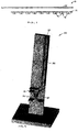
- Figs. 2 and 3 show a bead dispensing apparatus according to an embodiment of the present invention.
- the dispensing apparatus 30 can be used to dispense reagent beads 16 contained in the bead storage device 10 of Fig. 1 .
- the dispensing apparatus 30 includes a channel 32 in which to place the bead storage device 10 with the bead carrier 12 facing a support wall 34 of the channel 32 and the cover tape 20 facing a stripping wall 36 of the channel 32.
- the stripping wall 36 includes a stripping gap 40 disposed between a stripping edge 42 and an opposite edge 44.
- a dispense opening 48 is provided adjacent the opposite edge 44 on a side of the stripping wall 36 opposite from the stripping edge 42.
- the cover tape 20 is insertable through the stripping gap 40 to be pulled against the stripping edge 42 to peel the cover tape 20 from the bead carrier 12, thereby moving the wells 14 of the bead carrier 12 inside the channel 32 toward the dispense opening 48 and exposing the wells 14 individually to dispense the reagent beads 16 from the wells 14 through the dispense opening 48.
- the stripping wall 36 desirably includes a spout 50 coupled to the dispense opening 48 which is oriented generally downward to dispense the reagent beads 16 by gravity.
- the cover tape 20 is pulled against the stripping edge 42 in a direction generally opposite from a direction of travel of the bead carrier 12 toward the dispense opening 48.
- the generally opposite direction of pulling is convenient, but not required to separate the cover tape 20 from the bead carrier 12. Other directions can work.
- the pulling of the cover tape 20 creates the driving force for separating the cover tape 20 from the bead carrier 12 and for moving the bead carrier 12 toward the dispense opening 48 to dispense the reagent beads 16 from the wells 14 through the dispense opening 48.
- a counter 60 may be coupled to a portion of the cover tape 20 which has been peeled from the bead carrier 12 to count the number of wells 14 being exposed to dispense the reagent beads 16 based on a travel amount of the cover tape 20 with respect to the stripping edge 42. This is more easily done if the distance between the wells 14 is uniform.
- a counter may be coupled to a portion of the bead carrier 12 which has been separated from the cover tape 20 to count the number of exposed wells 14.
- Fig. 4 is an exploded perspective view of a bead dispensing apparatus according to another embodiment of the present invention.
- the dispensing apparatus 100 includes a base 102 and a cover 104 which are connected to form a housing with an interior.
- the base 102 includes in the interior thereof a channel 110 in which to place the bead storage device 10 with the bead carrier 12 facing a support wall 112 of the channel 110 and the cover tape 20 facing a stripping wall 114 of the channel 110.
- the stripping wall 114 includes a stripping gap 120 disposed between a stripping edge 122 and an opposite edge 124, and a dispense opening 128 provided adjacent the opposite edge 124 on a side of the stripping wall 114 opposite from the stripping edge 122.
- the stripping edge 122 includes a bend which bends outward from the channel 110 and backward away from the opposite edge 124 to guide the cover tape 20.
- the channel 110 is generally circular in shape.
- a spout 130 is desirably coupled to the dispense opening 128 and to be oriented generally downward to dispense the reagent beads 16 by gravity.
- the apparatus optionally includes a spout cap 131 for covering the spout 130 when the bead dispenser is not in use.
- Fig. 4 shows a desiccant 136 which may be placed inside the housing.
- a shaft 140 is provided in the base 102 to support a clutch 150 which is configured to grip and pull a leading end of the cover tape 20 inserted through the stripping gap 120 to pull the cover tape 20 against the stripping edge 122.
- a wheel 152 is coupled to the clutch 150 for turning the clutch 150 to pull the cover tape 20.
- the wheel 152 may include a corrugated surface for easier turning by the finger of a user.
- the clutch 150 preferably includes a ratchet mechanism to permit one-directional pulling of the cover tape 20.
- the ratchet mechanism may include a gear and a pawl.
- the wheel 152 is preferably exposed from the interior of the housing and sized to be rotatable by a user's finger or thumb.
- the clutch 150 is configured to pull the leading end of the cover tape 20 inserted through the stripping gap 120 against the stripping edge 122 to peel the cover tape 20 from the bead carrier 12 to move the wells 14 of the bead carrier 12 inside the channel 110 toward the dispense opening 128 with the spout 130 and expose the wells 14 individually one at a time to dispense the reagent beads 16 from the wells 14 through the dispense opening 128 and the spout 130.
- the wheel 152 is preferably configured to turn by a preset angle to move from one well to a next well toward the dispense opening 128 and expose the next well to dispense through the dispense opening 128 and spout 130.
- the preset angle is preferably at least about 60°C, and more preferably about 90-120°C.
- a counter may optionally be coupled to the clutch 150 which is connected to a portion of the cover tape 20 that has been peeled from the bead carrier 12 to count the number of wells 14 being exposed to dispense the reagent beads 16 based on a travel amount of the cover tape 20 (as pulled by turning the clutch).
- the housing of the apparatus 100 is transparent and has numbers 1 to X printed around its circumference, where X is the number of wells 14, to permit a user to see how many filled wells 14 remain by simple visual inspection.
- Fig. 6 shows one example of dispensing beads by turning the wheel 152 by a user's finger to pull the cover tape.
- the spout 130 is oriented generally downward the dispense the beads 16 by gravity.
- pulling of the cover tape can be performed by a machine either automatically or under the control of a user.
Description
- This application relates generally to systems and methods for storing and dispensing reagent beads for use in analyzing a sample.
- Many types of chemical reactions, such as nucleic acid amplification reactions, are important for research, medical, and industrial applications. Such reactions are used in clinical and biological research, detection and monitoring of infectious diseases, detection of mutations, detection of cancer markers, environmental monitoring, genetic identification, detection of pathogens in biodefense applications, and the like, e.g., Schweitzer et al., Current Opinion in Biotechnology, 12: 21-27 (2001); Koch, Nature Reviews Drug Discovery, 3: 749- 761 (2004). In particular, polymerase chain reactions (PCRs) have found applications in all of these areas, including applications for viral and bacterial detection, viral load monitoring, detection of rare and/or difficult-to-culture pathogens, rapid detection of bio-terror threats, detection of minimal residual disease in cancer patients, food pathogen testing, blood supply screening, and the like, e.g., Mackay, Clin. Microbiol. Infect., 10: 190-212 (2004); Bernard et al., Clinical Chemistry, 48: 1178-1185 (2002). In regard to PCR, key reasons for such widespread use are its speed and ease of use (typically performed within a few hours using standardized kits and relatively simple and low cost instruments), its sensitivity (often a few tens of copies of a target sequence in a sample can be detected), and its robustness (poor quality samples or preserved samples, such as forensic samples or fixed tissue samples are readily analyzed), Strachan and Read, Human Molecular Genetics 2 (John Wiley & Sons, New York, 1999).
NL 1 006 813 C1 WO 98/08092 A1 WO 00/15653 A1 - Reagent beads carrying a reagent are commonly used to provide the reagent for analyzing samples including, for example, analysis by nucleic acid amplification reactions such as PCR. In addition to nucleic acid amplification reactions, reagent beads may be used
in a wide variety of other chemical reaction/detection methods known in the art. Reagent beads are fragile and contain static charges that present static handling problems. - Embodiments of the present invention provide an efficient and effective technique for storing and dispensing reagent beads.
- In accordance with a first aspect of the present invention, a device for storing and dispensing reagent beads comprises a bead carrier including a plurality of wells; a plurality of reagent beads disposed in the plurality of wells; and a cover tape releasably attached to the bead carrier to cover the plurality of wells and retain the plurality of reagent beads in the plurality of wells of the bead carrier. The bead carrier and the cover tape each comprise an anti-static material. The cover tape is peelable from the bead carrier to expose the plurality of wells individually to dispense the plurality of reagent beads from the plurality of wells.
- In some embodiments, the anti-static material comprises styrene impregnated with carbon. In specific embodiments, the cover tape is releasably attached to the bead carrier by a pressure sensitive adhesive. Alternatively, the cover tape may be heat-sealed to the bead carrier. The bead carrier preferably includes a linear array of wells spaced by a generally uniform distance. The cover tape is peelable from the bead carrier to expose the plurality of wells individually one at a time. Preferably, at least a portion of each well is transparent.
- A second aspect of the present invention is directed to an apparatus for dispensing reagent beads contained in a bead storage device according to the first aspect of the present invention which includes a bead carrier having a plurality of wells; a plurality of reagent beads disposed in the plurality of wells; and a cover tape releasably attached to the bead carrier to cover the plurality of wells and retain the plurality of reagent beads in the plurality of wells of the bead carrier. The apparatus comprises a channel in which to place the bead storage device with the bead carrier facing a support wall of the channel and the cover tape facing a stripping wall of the channel. The stripping wall includes a stripping gap disposed between a stripping edge and an opposite edge, and a dispense opening provided adjacent the opposite edge on a side of the stripping wall opposite from the stripping edge. The cover tape is insertable through the stripping gap to be pulled against the stripping edge to peel the cover tape from the bead carrier to move the plurality of wells of the bead carrier inside the channel toward the dispense opening and
expose the plurality of wells individually to dispense the plurality of reagent beads from the plurality of wells through the dispense opening. Said apparatus comprises the bead storage device according to the first aspect. - In some embodiments, the stripping wall includes a spout coupled to the dispense opening and being oriented generally downward to dispense the reagent beads by gravity. A counter is coupled to a portion of the cover tape which has been peeled from the bead carrier to count the number of wells being exposed to dispense the reagent beads based on a travel amount of the cover tape with respect to the stripping edge.
- A third aspect of the invention is directed to an apparatus for dispensing reagent beads contained in a bead storage device according to the first aspect of the present invention which includes a bead carrier having a plurality of wells; a plurality of reagent beads disposed in the plurality of wells; and a cover tape releasably attached to the bead carrier to cover the plurality of wells and retain the plurality of reagent beads in the plurality of wells of the bead carrier. The apparatus comprises a housing having in an interior thereof a channel in which to place the bead storage device with the bead carrier facing a support wall of the channel and the cover tape facing a stripping wall of the channel, wherein the stripping wall includes a stripping gap disposed between a stripping edge and an opposite edge, and a dispense opening provided adjacent the opposite edge on a side of the stripping wall opposite from the stripping edge; a clutch configured to pull a leading end of the cover tape inserted through the stripping gap to pull the cover tape against the stripping edge; and a wheel coupled to the clutch for turning the clutch to pull the cover tape. Said apparatus comprises the bead storage device according to the first aspect.
- In some embodiments, the clutch includes a ratchet mechanism to permit one-directional pulling of the cover tape. The wheel is exposed from the interior of the housing and sized to be rotatable by a user's finger or thumb. The stripping wall includes a spout coupled to the dispense opening and being oriented generally downward to dispense the reagent beads by gravity. The stripping edge includes a bend which bends outward from the channel and backward away from the opposite edge to guide the cover tape. The channel is generally circular in shape. The clutch is configured to pull the leading end of the cover tape inserted through the stripping gap against the stripping edge to peel the cover tape from the bead carrier to move the plurality of wells of the bead carrier inside the channel toward the dispense opening and expose the plurality of wells individually one at a time to dispense the reagent beads from the plurality of wells through the dispense opening. The wheel is configured to turn by at least about 60°C to move from one well to a next well toward the
dispense opening and expose the next well to dispense through the dispense opening. A counter is coupled to the clutch to count the number of wells being exposed to dispense the reagent beads based on a travel amount of the cover tape. - A fourth aspect of the present invention is directed to a method of dispensing reagent beads contained in a bead storage device according to the first aspect of the present invention which includes a bead carrier having a plurality of wells; a plurality of reagent beads disposed in the plurality of wells; and a cover tape releasably attached to the bead carrier to cover the plurality of wells and retain the plurality of reagent beads in the plurality of wells of the bead carrier. The method comprises placing the bead storage device in a channel with the bead carrier facing a support wall of the channel and the cover tape facing a stripping wall of the channel, wherein the stripping wall includes a stripping gap disposed between a stripping edge and an opposite edge, and a dispense opening provided adjacent the opposite edge on a side of the stripping wall opposite from the stripping edge. The method further comprises inserting the cover tape through the stripping gap; and pulling the cover tape against the stripping edge to peel the cover tape from the bead carrier to move the plurality of wells of the bead carrier inside the channel toward the dispense opening and expose the plurality of wells individually to dispense the plurality of reagent beads from the plurality of wells through the dispense opening.
-
-
Fig. 1 is an exploded elevational view of a reagent bead storage device according to an embodiment of the present invention. -
Fig. 2 is a perspective view of a bead dispensing apparatus according to an embodiment of the present invention. -
Fig. 3 is an elevational of the bead dispensing apparatus ofFig. 2 for dispensing reagent beads from the reagent bead storage device ofFig. 1 . -
Fig. 4 is an exploded perspective view of a bead dispensing apparatus according to another embodiment of the present invention. -
Fig. 5 is a perspective view showing the interior of the bead dispensing apparatus ofFig. 4 . -
Fig. 6 is an elevational view of the bead dispensing apparatus ofFig. 4 . -
Fig. 1 is an exploded view of a reagent bead storage device for storing reagent beads to be dispensed. Thestorage device 10 includes abead carrier 12 having a plurality ofwells 14 and a plurality ofreagent beads 16 disposed in thewells 14. Thebead carrier 12 may be a flexible tape having thewells 14 formed therein, or the bead carrier may be a rigid or flexible molded part.Fig. 1 shows onebead 16 in each well 14, but the number of beads may vary in other embodiments. Acover tape 20 is releasably attached to thebead carrier 12 to cover thewells 14 and retain thereagent beads 16 in thewells 14 of thebead carrier 12. Thebead carrier 12 and thecover tape 20 are made of an anti-static material. Thecover tape 20 is peelable from thebead carrier 12 to expose thewells 14 individually to dispense thereagent beads 16 from thewells 14, as described in more detail below. - An example of a suitable anti-static material is styrene impregnated with carbon. Of course, other anti-static materials may be used. Examples of other anti-static materials includes, without limitation, metals and treated plastics (e.g., plastics impregnated with a conductive metal or plastics given a surface treatment). The
cover tape 20 may be releasably attached to thebead carrier 12 by a pressure sensitive adhesive, or heat-sealed to thebead carrier 12. The cover tape is preferably peelable from the bead carrier using a manual force exerted by one or more fingers of the user. InFig. 1 , the bead carrier includes a linear array ofwells 14 spaced by a generally uniform distance. Thecover tape 20 is peelable from thebead carrier 12 to expose the plurality ofwells 14 individually one at a time. Other arrangements or configurations are possible, including nonlinear arrangement of wells and nonuniform distances between wells. At least a portion of each well 14 is preferably transparent to allow one to see the content inside. -
Figs. 2 and3 show a bead dispensing apparatus according to an embodiment of the present invention. The dispensingapparatus 30 can be used to dispensereagent beads 16 contained in thebead storage device 10 ofFig. 1 . The dispensingapparatus 30 includes achannel 32 in which to place thebead storage device 10 with thebead carrier 12 facing a support wall 34 of thechannel 32 and thecover tape 20 facing a strippingwall 36 of thechannel 32. The strippingwall 36 includes a strippinggap 40 disposed between a strippingedge 42 and an opposite edge 44. A dispenseopening 48 is provided adjacent the opposite edge 44 on a side of the strippingwall 36 opposite from the strippingedge 42. Thecover tape 20 is insertable through the strippinggap 40 to be pulled against the strippingedge 42 to
peel thecover tape 20 from thebead carrier 12, thereby moving thewells 14 of thebead carrier 12 inside thechannel 32 toward the dispenseopening 48 and exposing thewells 14 individually to dispense thereagent beads 16 from thewells 14 through the dispenseopening 48. The strippingwall 36 desirably includes aspout 50 coupled to the dispenseopening 48 which is oriented generally downward to dispense thereagent beads 16 by gravity. - As seen in
Fig. 3 , thecover tape 20 is pulled against the strippingedge 42 in a direction generally opposite from a direction of travel of thebead carrier 12 toward the dispenseopening 48. The generally opposite direction of pulling is convenient, but not required to separate thecover tape 20 from thebead carrier 12. Other directions can work. The pulling of thecover tape 20 creates the driving force for separating thecover tape 20 from thebead carrier 12 and for moving thebead carrier 12 toward the dispenseopening 48 to dispense thereagent beads 16 from thewells 14 through the dispenseopening 48. Acounter 60 may be coupled to a portion of thecover tape 20 which has been peeled from thebead carrier 12 to count the number ofwells 14 being exposed to dispense thereagent beads 16 based on a travel amount of thecover tape 20 with respect to the strippingedge 42. This is more easily done if the distance between thewells 14 is uniform. In an alternative embodiment, a counter may be coupled to a portion of thebead carrier 12 which has been separated from thecover tape 20 to count the number of exposedwells 14. -
Fig. 4 is an exploded perspective view of a bead dispensing apparatus according to another embodiment of the present invention. The dispensingapparatus 100 includes abase 102 and acover 104 which are connected to form a housing with an interior. Thebase 102 includes in the interior thereof achannel 110 in which to place thebead storage device 10 with thebead carrier 12 facing asupport wall 112 of thechannel 110 and thecover tape 20 facing a stripping wall 114 of thechannel 110. The stripping wall 114 includes a strippinggap 120 disposed between a strippingedge 122 and anopposite edge 124, and a dispense opening 128 provided adjacent theopposite edge 124 on a side of the stripping wall 114 opposite from the strippingedge 122. In the embodiment shown, the strippingedge 122 includes a bend which bends outward from thechannel 110 and backward away from theopposite edge 124 to guide thecover tape 20. Thechannel 110 is generally circular in shape. Aspout 130 is desirably coupled to the dispenseopening 128 and to be oriented generally downward to dispense thereagent beads 16 by gravity. The apparatus optionally includes aspout cap 131 for covering thespout 130 when the bead dispenser is not in use.Fig. 4 shows adesiccant 136 which may be placed inside the housing. - A
shaft 140 is provided in the base 102 to support a clutch 150 which is configured to grip and pull a leading end of thecover tape 20 inserted through the strippinggap 120 to pull thecover tape 20 against the strippingedge 122. Awheel 152 is coupled to the clutch 150 for turning the clutch 150 to pull thecover tape 20. Thewheel 152 may include a corrugated surface for easier turning by the finger of a user. The clutch 150 preferably includes a ratchet mechanism to permit one-directional pulling of thecover tape 20. The ratchet mechanism may include a gear and a pawl. As seen inFigs. 5 and 6 , thewheel 152 is preferably exposed from the interior of the housing and sized to be rotatable by a user's finger or thumb. - As seen in
Fig. 5 , the clutch 150 is configured to pull the leading end of thecover tape 20 inserted through the strippinggap 120 against the strippingedge 122 to peel thecover tape 20 from thebead carrier 12 to move thewells 14 of thebead carrier 12 inside thechannel 110 toward the dispense opening 128 with thespout 130 and expose thewells 14 individually one at a time to dispense thereagent beads 16 from thewells 14 through the dispenseopening 128 and thespout 130. To avoid accidentally dispensing beads, thewheel 152 is preferably configured to turn by a preset angle to move from one well to a next well toward the dispenseopening 128 and expose the next well to dispense through the dispenseopening 128 andspout 130. For example, the preset angle is preferably at least about 60°C, and more preferably about 90-120°C. A counter may optionally be coupled to the clutch 150 which is connected to a portion of thecover tape 20 that has been peeled from thebead carrier 12 to count the number ofwells 14 being exposed to dispense thereagent beads 16 based on a travel amount of the cover tape 20 (as pulled by turning the clutch). In some embodiments, the housing of theapparatus 100 is transparent and has numbers 1 to X printed around its circumference, where X is the number ofwells 14, to permit a user to see how many filledwells 14 remain by simple visual inspection. -
Fig. 6 shows one example of dispensing beads by turning thewheel 152 by a user's finger to pull the cover tape. Thespout 130 is oriented generally downward the dispense thebeads 16 by gravity. In other embodiments, pulling of the cover tape can be performed by a machine either automatically or under the control of a user. - It is to be understood that the above description is intended to be illustrative and not restrictive. Many embodiments will be apparent to those of skill in the art upon reviewing the above description. The scope of the invention should, therefore, be determined not with reference to the above description, but instead should be determined with reference to the appended claims.
Claims (33)
- A device (10) for storing and dispensing reagent beads (16), the device comprising:a bead carrier (12) including a plurality of wells (14);a plurality of reagent beads (16) disposed in the plurality of wells (14); anda cover tape (20) releasably attached to the bead carrier (12) to cover the plurality of wells (14) and retain the plurality of reagent beads (16) in the plurality of wells (14) of the bead carrier (12);wherein the bead carrier (12) and the cover tape (20) each comprise an anti-static material; andwherein the cover tape (20) is peelable from the bead carrier (12) to expose the plurality of wells (14) individually to dispense the plurality of reagent beads (16) from the plurality of wells (14).
- The device of claim 1 wherein the anti-static material comprises styrene with impregnated carbon.
- The device of claim 1 wherein the cover tape (20) is releasably attached to the bead carrier (12) by a pressure sensitive adhesive.
- The device of claim 1 wherein the bead carrier (12) includes a linear array of wells (14) spaced by a generally uniform distance.
- The device of claim 1 wherein the cover tape (20) is peelable from the bead carrier (12) to expose the plurality of wells (14) individually one at a time.
- The device of claim 1 wherein at least a portion of each well (14) is transparent.
- An apparatus (30, 100) for dispensing reagent beads (16) contained in a bead storage device (10) of any one of the previous claims, the apparatus comprising:the bead storage device (10) of any one of claims 1 to 6;a channel (32, 110) in which to place the bead storage device (10) with the bead carrier (12) facing a support wall (34, 112) of the channel (32, 110) and the cover tape (20) facing a stripping wall (36, 114) of the channel (32, 110);wherein the stripping wall (36, 114) includes a stripping gap (40, 120) disposed between a stripping edge (42, 122) and an opposite edge (44, 124), and a dispense opening (48, 128) provided adjacent the opposite edge (44, 124) on a side of the stripping wall (36, 114) opposite from the stripping edge (42, 122), the cover tape (20) being insertable through the stripping gap (40, 120) to be pulled against the stripping edge (42, 122) to peel the cover tape (20) from the bead carrier (12) to move the plurality of wells (14) of the bead carrier (12) inside the channel (32, 110) toward the dispense opening (48, 128) and expose the plurality of wells (14) individually to dispense the plurality of reagent beads (16) from the plurality of wells (14) through the dispense opening (48, 128).
- The apparatus of claim 7 wherein the stripping wall (36, 114) includes a spout (50, 130) coupled to the dispense opening (48, 128) and being oriented generally downward to dispense the reagent beads (16) by gravity.
- The apparatus of claim 7 wherein the stripping edge (122) includes a bend which bends outward from the channel (110) and backward away from the opposite edge (124) to guide the cover tape (20).
- The apparatus of claim 7 wherein the channel (110) is generally circular in shape.
- The apparatus of claim 7 further comprising a clutch (150) configured to pull a leading end of the cover tape (20) inserted through the stripping gap (120).
- The apparatus of claim 11 wherein the clutch (150) includes a ratchet mechanism to permit one-directional pulling of the cover tape (20).
- The apparatus of claim 11 further comprising a wheel (152) coupled to the clutch (150) for turning the clutch (150) to pull the cover tape (20).
- The apparatus of claim 13 further comprising a housing (102, 104) including the channel (110) disposed in an interior thereof, the wheel being exposed from the interior of the housing (102, 104).
- The apparatus of claim 7 wherein the cover tape (20) is insertable through the stripping gap (40) to be pulled against the stripping edge (42) to peel the cover tape (20) from the bead carrier (12) to move the plurality of wells (14) of the bead carrier (12) inside the channel (32) toward the dispense opening (48) and expose the plurality of wells (14) individually one at a time to dispense the reagent beads (16) from the plurality of wells (14) through the dispense opening (48).
- The apparatus of claim 7 further comprising a counter (60) coupled to a portion of the cover tape (20) which has been peeled from the bead carrier (12) to count the number of wells (14) being exposed to dispense the reagent beads (16) based on a travel amount of the cover tape (20) with respect to the stripping edge (42).
- An apparatus (100) for dispensing reagent beads (16) contained in a bead storage device (10) according to any one of claims 1 through 6, the apparatus comprising:the bead storage device (10) of any one of claims 1 to 6;a housing (102, 104) having in an interior thereof a channel (110) in which to place the bead storage device (10) with the bead carrier (12) facing a support wall (112) of the channel (110) and the cover tape (20) facing a stripping wall (114) of the channel (110), wherein the stripping wall (114) includes a stripping gap (120) disposed between a stripping edge (122) and an opposite edge (124), and a dispense opening (128) provided adjacent the opposite edge (124) on a side of the stripping wall (114) opposite from the stripping edge (122);a clutch (150) configured to pull a leading end of the cover tape (20) inserted through the stripping gap (120) to pull the cover tape (20) against the stripping edge (122); anda wheel (152) coupled to the clutch (150) for turning the clutch (150) to pull the cover tape (20).
- The apparatus of claim 17 wherein the clutch (150) includes a ratchet mechanism to permit one-directional pulling of the cover tape (20).
- The apparatus of claim 17 wherein the wheel (152) is exposed from the interior of the housing (102, 104) and sized to be rotatable by a user's finger or thumb.
- The apparatus of claim 17 wherein the stripping wall (114) includes a spout (130) coupled to the dispense opening and being oriented generally downward to dispense the reagent beads (16) by gravity.
- The apparatus of claim 17 wherein the stripping edge includes a bend which bends outward from the channel (110) and backward away from the opposite edge to guide the cover tape (20).
- The apparatus of claim 17 wherein the channel (110) is generally circular in shape.
- The apparatus of claim 17 wherein the clutch (150) is configured to pull the leading end of the cover tape (20) inserted through the stripping gap (120) against the stripping edge (122) to peel the cover tape (20) from the bead carrier (12) to move the plurality of wells (14) of the bead carrier (12) inside the channel (110) toward the dispense opening (128) and expose the plurality of wells (14) individually one at a time to dispense the reagent beads (16) from the plurality of wells (14) through the dispense opening (128).
- The apparatus of claim 23 wherein the wheel (152) is configured to turn by at least about 60° to move from one well (14) to a next well (14) toward the dispense opening (128) and expose the next well (14) to dispense through the dispense opening (128).
- The apparatus of claim 17 further comprising a counter coupled to the clutch (150) to count the number of wells (14) being exposed to dispense the reagent beads (16) based on a travel amount of the cover tape (20).
- A method of dispensing reagent beads (16) contained in a bead storage device (10) of any one of the previous claims 1 to 6, the method comprising:placing the bead storage device (10) in a channel (32, 110) with the bead carrier (12) facing a support wall (34, 112) of the channel (32, 110) and the cover tape (20) facing a stripping wall (36, 114) of the channel (32, 110), wherein the stripping wall (36, 114) includes a stripping gap (40, 120) disposed between a stripping edge (42, 122) and an opposite edge (44, 124), and a dispense opening (48, 128) provided adjacent the opposite edge (44, 124) on a side of the stripping wall (36, 114) opposite from the stripping edge (42, 122);inserting the cover tape (20) through the stripping gap (40, 120);pulling the cover tape (20) against the stripping edge (42, 122) to peel the cover tape (20) from the bead carrier (12) to move the plurality of wells (14) of the bead carrier (12) inside the channel (32, 110) toward the dispense opening (48, 128) and expose the plurality of wells (14) individually to dispense the plurality of reagent beads (16) from the plurality of wells (14) through the dispense opening (48, 128).
- The method of claim 26 wherein the cover tape (20) is pulled against the stripping edge (42, 122) in a direction generally opposite from a direction of travel of the bead carrier (12) toward the dispense opening (48, 128).
- The method of claim 26 further comprising orienting the dispense opening (48, 128) generally downward with respect to the wells (14) to dispense the reagent beads (16) by gravity.
- The method of claim 26 further comprising providing a clutch (150) to pull a leading edge of the cover tape (20) to pull the cover tape (20) against the stripping edge (122) to peel the cover tape (20) from the bead carrier (12).
- The method of claim 29 wherein the clutch (150) includes a ratchet mechanism to permit one-directional pulling of the cover tape (20).
- The method of claim 29 wherein pulling the cover tape (20) comprises turning a wheel (152) coupled to the clutch (150).
- The method of claim 26 wherein the cover tape (20) is pulled against the stripping edge (42, 122) to peel the cover tape (20) from the bead carrier (12) to move the plurality of wells (14) of the bead carrier (12) inside the channel (32, 110) toward the dispense opening (48, 128) and expose the plurality of wells (14) individually one at a time to dispense the reagent beads (16) from the plurality of wells (14) through the dispense opening (48, 128).
- The method of claim 32 further comprising counting the number of wells (14) being exposed to dispense the reagent beads (16) based on a travel amount of the cover tape (20) with respect to the stripping edge (42, 122).
Applications Claiming Priority (2)
| Application Number | Priority Date | Filing Date | Title |
|---|---|---|---|
| US11/146,304 US7575721B2 (en) | 2005-06-06 | 2005-06-06 | Method and apparatus for storing and dispensing reagent beads |
| PCT/US2006/021147 WO2006132886A2 (en) | 2005-06-06 | 2006-05-31 | Method and apparatus for storing and dispensing reagent beads |
Publications (3)
| Publication Number | Publication Date |
|---|---|
| EP1896181A2 EP1896181A2 (en) | 2008-03-12 |
| EP1896181A4 EP1896181A4 (en) | 2012-10-17 |
| EP1896181B1 true EP1896181B1 (en) | 2019-03-20 |
Family
ID=37494247
Family Applications (1)
| Application Number | Title | Priority Date | Filing Date |
|---|---|---|---|
| EP06771753.8A Active EP1896181B1 (en) | 2005-06-06 | 2006-05-31 | Method and apparatus for storing and dispensing reagent beads |
Country Status (8)
| Country | Link |
|---|---|
| US (5) | US7575721B2 (en) |
| EP (1) | EP1896181B1 (en) |
| JP (1) | JP4934668B2 (en) |
| CN (1) | CN101193706B (en) |
| AU (1) | AU2006255603B2 (en) |
| CA (1) | CA2610013C (en) |
| HK (1) | HK1121710A1 (en) |
| WO (1) | WO2006132886A2 (en) |
Families Citing this family (21)
| Publication number | Priority date | Publication date | Assignee | Title |
|---|---|---|---|---|
| WO2006039293A2 (en) * | 2004-09-29 | 2006-04-13 | University Of Virginia Patent Foundation | Localized control of thermal properties on microdevices and applications thereof |
| US8056881B2 (en) | 2004-10-13 | 2011-11-15 | University Of Virginia Patent Foundation | Electrostatic actuation for management of flow in micro-total analysis systems (μ-TAS) and related method thereof |
| JP4922185B2 (en) * | 2004-12-22 | 2012-04-25 | ユニバーシティ・オブ・ヴァージニア・パテント・ファウンデーション | Use of microwaves for thermal or non-thermal applications in micro or nanoscale devices |
| US8343755B2 (en) * | 2005-08-01 | 2013-01-01 | University Of Virginia Patent Foundation | Microdevices for chemical sensing and chemical actuation |
| CA2620285C (en) | 2005-08-23 | 2016-08-16 | University Of Virginia Patent Foundation | Passive components for micro-fluidic flow profile shaping and related method thereof |
| US20110033922A1 (en) * | 2005-10-04 | 2011-02-10 | Landers James P | Microchip-based acoustic trapping or capture of cells for forensic analysis and related method thereof |
| WO2007047336A2 (en) | 2005-10-12 | 2007-04-26 | University Of Virginia Patent Foundation | Integrated microfluidic analysis systems |
| AU2007100449A4 (en) * | 2007-03-23 | 2007-08-02 | Moose Enterprise Pty Ltd | A bead dispensing system |
| GB0913258D0 (en) | 2009-07-29 | 2009-09-02 | Dynex Technologies Inc | Reagent dispenser |
| US9523701B2 (en) | 2009-07-29 | 2016-12-20 | Dynex Technologies, Inc. | Sample plate systems and methods |
| FR2950358B1 (en) | 2009-09-18 | 2015-09-11 | Biomerieux Sa | SIMPLIFIED NUCLEIC ACID AMPLIFICATION DEVICE AND METHOD FOR IMPLEMENTING THE SAME |
| JP5663985B2 (en) * | 2009-12-16 | 2015-02-04 | ソニー株式会社 | Cell for microbead inspection and method for analyzing microbead |
| US9987576B2 (en) | 2012-12-10 | 2018-06-05 | University Of Virginia Patent Foundation | Frequency-based filtering of mechanical actuation using fluidic device |
| JP6474970B2 (en) * | 2014-06-13 | 2019-02-27 | 株式会社スペース・バイオ・ラボラトリーズ | Clinostat |
| CN104240343A (en) * | 2014-09-01 | 2014-12-24 | 北京泛亚电通工贸有限责任公司 | Well cover as well as monitoring method and monitoring system thereof |
| JP6522346B2 (en) * | 2015-01-13 | 2019-05-29 | 株式会社スペース・バイオ・ラボラトリーズ | Clinostat |
| FR3035320B1 (en) * | 2015-04-22 | 2017-04-28 | W2Next | DISPENSER OF MEDICAMENTS TO A PATIENT |
| GB201620671D0 (en) * | 2016-12-05 | 2017-01-18 | Conceptomed As | Storage device |
| FR3065532B1 (en) * | 2017-04-20 | 2020-07-17 | Diagnostica Stago | BALL CONDITIONING DEVICE FOR REACTION CELLS FOR AN ANALYZING APPARATUS |
| CN111187718B (en) * | 2020-02-21 | 2021-02-09 | 厦门大学 | Nucleic acid extraction device and nucleic acid detection system |
| CN112547151B (en) * | 2020-10-19 | 2022-02-18 | 宁夏菲杰特检测有限公司 | Reagent quantitative extraction device used in chemical experiment process |
Family Cites Families (23)
| Publication number | Priority date | Publication date | Assignee | Title |
|---|---|---|---|---|
| US4935274A (en) * | 1988-08-26 | 1990-06-19 | E. I. Du Pont De Nemours And Company | Lid structure |
| JPH0731860A (en) * | 1993-07-20 | 1995-02-03 | Araki Tekko:Kk | Dispersion apparatus |
| US5575403A (en) * | 1995-01-13 | 1996-11-19 | Bayer Corporation | Dispensing instrument for fluid monitoring sensors |
| US5616299A (en) * | 1995-06-06 | 1997-04-01 | Pharmacia Biotech, Inc. | Dispenser for dried biological reagent spheres |
| US5885529A (en) * | 1996-06-28 | 1999-03-23 | Dpc Cirrus, Inc. | Automated immunoassay analyzer |
| JP2002515044A (en) * | 1996-08-21 | 2002-05-21 | スミスクライン・ビーチャム・コーポレイション | A rapid method for sequencing and synthesizing bead-based combinatorial libraries |
| JPH1086597A (en) * | 1996-09-13 | 1998-04-07 | Moritex Corp | Manufacturing device for marble picture |
| US6030692A (en) * | 1996-09-13 | 2000-02-29 | Netpco Incorporated | Cover tape for formed tape packing system and process for making same |
| NL1006813C1 (en) | 1997-08-20 | 1998-01-21 | Sipke Wadman | Packaging containing solid reaction carrier for chemical synthesis |
| WO1999054711A1 (en) * | 1998-04-17 | 1999-10-28 | Ljl Biosystems, Inc. | Sample-holding devices and systems |
| GB9820208D0 (en) * | 1998-09-16 | 1998-11-11 | Central Research Lab Ltd | Apparatus for and method of storing a plurality of chemical compounds |
| US6887431B1 (en) * | 1999-02-16 | 2005-05-03 | Applera Corporation | Bead dispensing system |
| US6601729B1 (en) * | 1999-03-26 | 2003-08-05 | Papp Enterprises, Llc | Automated portable medication radial dispensing apparatus and method using a carrier tape |
| JP3390377B2 (en) * | 1999-10-05 | 2003-03-24 | 株式会社日立製作所 | Reactor |
| EP1103304A3 (en) * | 1999-11-29 | 2003-06-25 | Becton, Dickinson and Company | Self-venting reagent vessel and method of delivering a reagent to an analyzing instrument or other apparatus |
| GB0026647D0 (en) * | 2000-10-31 | 2000-12-13 | Glaxo Group Ltd | Medicament dispenser |
| JP4001468B2 (en) * | 2001-05-28 | 2007-10-31 | 電気化学工業株式会社 | Carrier tape body |
| GB0110476D0 (en) * | 2001-04-30 | 2001-06-20 | Secr Defence | Reagent delivery system |
| EP1581442A1 (en) * | 2002-11-14 | 2005-10-05 | E.I. du Pont de Nemours and Company | Tablet dispenser |
| US7533514B2 (en) * | 2003-04-25 | 2009-05-19 | Boston Scientific Scimed, Inc. | Method and apparatus for automated handling of medical devices during manufacture |
| JP2004337108A (en) * | 2003-05-16 | 2004-12-02 | Hitachi High-Technologies Corp | Apparatus for refining nucleic acid, chip for catching nucleic acid and method for refining nucleic acid |
| WO2005110192A1 (en) * | 2004-05-14 | 2005-11-24 | Olympus Corporation | Insertion device |
| US20070051072A1 (en) * | 2005-09-06 | 2007-03-08 | Joseph Lai | Pills on tape and reel |
-
2005
- 2005-06-06 US US11/146,304 patent/US7575721B2/en active Active
-
2006
- 2006-05-31 EP EP06771753.8A patent/EP1896181B1/en active Active
- 2006-05-31 CN CN2006800197969A patent/CN101193706B/en active Active
- 2006-05-31 JP JP2008515760A patent/JP4934668B2/en active Active
- 2006-05-31 WO PCT/US2006/021147 patent/WO2006132886A2/en active Application Filing
- 2006-05-31 CA CA2610013A patent/CA2610013C/en active Active
- 2006-05-31 AU AU2006255603A patent/AU2006255603B2/en active Active
-
2008
- 2008-12-02 HK HK08113137.9A patent/HK1121710A1/en unknown
-
2009
- 2009-07-30 US US12/512,833 patent/US8409530B2/en active Active
- 2009-07-30 US US12/512,926 patent/US8409531B2/en active Active
-
2013
- 2013-03-25 US US13/849,640 patent/US8747782B2/en active Active
-
2014
- 2014-05-02 US US14/268,682 patent/US9446409B2/en active Active
Non-Patent Citations (1)
| Title |
|---|
| None * |
Also Published As
| Publication number | Publication date |
|---|---|
| US20090289076A1 (en) | 2009-11-26 |
| US7575721B2 (en) | 2009-08-18 |
| HK1121710A1 (en) | 2009-04-30 |
| AU2006255603A1 (en) | 2006-12-14 |
| CN101193706B (en) | 2012-12-12 |
| US8409531B2 (en) | 2013-04-02 |
| US8409530B2 (en) | 2013-04-02 |
| JP4934668B2 (en) | 2012-05-16 |
| AU2006255603B2 (en) | 2011-08-18 |
| EP1896181A4 (en) | 2012-10-17 |
| US20140335627A1 (en) | 2014-11-13 |
| US20140030817A1 (en) | 2014-01-30 |
| CA2610013A1 (en) | 2006-12-14 |
| US20090308886A1 (en) | 2009-12-17 |
| WO2006132886A3 (en) | 2007-12-21 |
| CN101193706A (en) | 2008-06-04 |
| EP1896181A2 (en) | 2008-03-12 |
| US9446409B2 (en) | 2016-09-20 |
| US20060275178A1 (en) | 2006-12-07 |
| US8747782B2 (en) | 2014-06-10 |
| WO2006132886A2 (en) | 2006-12-14 |
| JP2008542789A (en) | 2008-11-27 |
| CA2610013C (en) | 2014-01-21 |
Similar Documents
| Publication | Publication Date | Title |
|---|---|---|
| EP1896181B1 (en) | Method and apparatus for storing and dispensing reagent beads | |
| US9480983B2 (en) | Unitized reagent strip | |
| US6426215B1 (en) | PCR plate cover and maintaining device | |
| EP1340982A2 (en) | Assay work station | |
| JPH06509253A (en) | Reusable seals for diagnostic test reagent packs | |
| US20010007642A1 (en) | Sealing apparatus for use with microplates | |
| US20060154281A1 (en) | Reaction chamber | |
| AU2799199A (en) | Sealing apparatus for use with microplates | |
| WO2003086200A1 (en) | Disk testing apparatus | |
| AU2002248647A1 (en) | PCR plate cover and maintaining device | |
| AU5071102A (en) | A substance transfer device |
Legal Events
| Date | Code | Title | Description |
|---|---|---|---|
| PUAI | Public reference made under article 153(3) epc to a published international application that has entered the european phase |
Free format text: ORIGINAL CODE: 0009012 |
|
| 17P | Request for examination filed |
Effective date: 20071207 |
|
| AK | Designated contracting states |
Kind code of ref document: A2 Designated state(s): AT BE BG CH CY CZ DE DK EE ES FI FR GB GR HU IE IS IT LI LT LU LV MC NL PL PT RO SE SI SK TR |
|
| AX | Request for extension of the european patent |
Extension state: AL BA HR MK YU |
|
| DAX | Request for extension of the european patent (deleted) | ||
| A4 | Supplementary search report drawn up and despatched |
Effective date: 20120917 |
|
| RIC1 | Information provided on ipc code assigned before grant |
Ipc: B01L 3/02 20060101AFI20120911BHEP Ipc: B01J 19/00 20060101ALI20120911BHEP |
|
| 17Q | First examination report despatched |
Effective date: 20160310 |
|
| GRAP | Despatch of communication of intention to grant a patent |
Free format text: ORIGINAL CODE: EPIDOSNIGR1 |
|
| STAA | Information on the status of an ep patent application or granted ep patent |
Free format text: STATUS: GRANT OF PATENT IS INTENDED |
|
| INTG | Intention to grant announced |
Effective date: 20181008 |
|
| GRAS | Grant fee paid |
Free format text: ORIGINAL CODE: EPIDOSNIGR3 |
|
| GRAA | (expected) grant |
Free format text: ORIGINAL CODE: 0009210 |
|
| STAA | Information on the status of an ep patent application or granted ep patent |
Free format text: STATUS: THE PATENT HAS BEEN GRANTED |
|
| AK | Designated contracting states |
Kind code of ref document: B1 Designated state(s): AT BE BG CH CY CZ DE DK EE ES FI FR GB GR HU IE IS IT LI LT LU LV MC NL PL PT RO SE SI SK TR |
|
| REG | Reference to a national code |
Ref country code: GB Ref legal event code: FG4D |
|
| REG | Reference to a national code |
Ref country code: CH Ref legal event code: EP |
|
| REG | Reference to a national code |
Ref country code: DE Ref legal event code: R096 Ref document number: 602006057644 Country of ref document: DE |
|
| REG | Reference to a national code |
Ref country code: AT Ref legal event code: REF Ref document number: 1109998 Country of ref document: AT Kind code of ref document: T Effective date: 20190415 |
|
| REG | Reference to a national code |
Ref country code: IE Ref legal event code: FG4D |
|
| REG | Reference to a national code |
Ref country code: CH Ref legal event code: NV Representative=s name: MICHELI AND CIE SA, CH |
|
| REG | Reference to a national code |
Ref country code: SE Ref legal event code: TRGR |
|
| REG | Reference to a national code |
Ref country code: NL Ref legal event code: MP Effective date: 20190320 |
|
| PG25 | Lapsed in a contracting state [announced via postgrant information from national office to epo] |
Ref country code: FI Free format text: LAPSE BECAUSE OF FAILURE TO SUBMIT A TRANSLATION OF THE DESCRIPTION OR TO PAY THE FEE WITHIN THE PRESCRIBED TIME-LIMIT Effective date: 20190320 Ref country code: LT Free format text: LAPSE BECAUSE OF FAILURE TO SUBMIT A TRANSLATION OF THE DESCRIPTION OR TO PAY THE FEE WITHIN THE PRESCRIBED TIME-LIMIT Effective date: 20190320 |
|
| REG | Reference to a national code |
Ref country code: LT Ref legal event code: MG4D |
|
| PG25 | Lapsed in a contracting state [announced via postgrant information from national office to epo] |
Ref country code: NL Free format text: LAPSE BECAUSE OF FAILURE TO SUBMIT A TRANSLATION OF THE DESCRIPTION OR TO PAY THE FEE WITHIN THE PRESCRIBED TIME-LIMIT Effective date: 20190320 Ref country code: GR Free format text: LAPSE BECAUSE OF FAILURE TO SUBMIT A TRANSLATION OF THE DESCRIPTION OR TO PAY THE FEE WITHIN THE PRESCRIBED TIME-LIMIT Effective date: 20190621 Ref country code: LV Free format text: LAPSE BECAUSE OF FAILURE TO SUBMIT A TRANSLATION OF THE DESCRIPTION OR TO PAY THE FEE WITHIN THE PRESCRIBED TIME-LIMIT Effective date: 20190320 Ref country code: BG Free format text: LAPSE BECAUSE OF FAILURE TO SUBMIT A TRANSLATION OF THE DESCRIPTION OR TO PAY THE FEE WITHIN THE PRESCRIBED TIME-LIMIT Effective date: 20190620 |
|
| REG | Reference to a national code |
Ref country code: AT Ref legal event code: MK05 Ref document number: 1109998 Country of ref document: AT Kind code of ref document: T Effective date: 20190320 |
|
| PG25 | Lapsed in a contracting state [announced via postgrant information from national office to epo] |
Ref country code: EE Free format text: LAPSE BECAUSE OF FAILURE TO SUBMIT A TRANSLATION OF THE DESCRIPTION OR TO PAY THE FEE WITHIN THE PRESCRIBED TIME-LIMIT Effective date: 20190320 Ref country code: RO Free format text: LAPSE BECAUSE OF FAILURE TO SUBMIT A TRANSLATION OF THE DESCRIPTION OR TO PAY THE FEE WITHIN THE PRESCRIBED TIME-LIMIT Effective date: 20190320 Ref country code: CZ Free format text: LAPSE BECAUSE OF FAILURE TO SUBMIT A TRANSLATION OF THE DESCRIPTION OR TO PAY THE FEE WITHIN THE PRESCRIBED TIME-LIMIT Effective date: 20190320 Ref country code: ES Free format text: LAPSE BECAUSE OF FAILURE TO SUBMIT A TRANSLATION OF THE DESCRIPTION OR TO PAY THE FEE WITHIN THE PRESCRIBED TIME-LIMIT Effective date: 20190320 Ref country code: PT Free format text: LAPSE BECAUSE OF FAILURE TO SUBMIT A TRANSLATION OF THE DESCRIPTION OR TO PAY THE FEE WITHIN THE PRESCRIBED TIME-LIMIT Effective date: 20190720 Ref country code: SK Free format text: LAPSE BECAUSE OF FAILURE TO SUBMIT A TRANSLATION OF THE DESCRIPTION OR TO PAY THE FEE WITHIN THE PRESCRIBED TIME-LIMIT Effective date: 20190320 Ref country code: IT Free format text: LAPSE BECAUSE OF FAILURE TO SUBMIT A TRANSLATION OF THE DESCRIPTION OR TO PAY THE FEE WITHIN THE PRESCRIBED TIME-LIMIT Effective date: 20190320 |
|
| REG | Reference to a national code |
Ref country code: DE Ref legal event code: R082 Ref document number: 602006057644 Country of ref document: DE Representative=s name: ZWICKER SCHNAPPAUF & PARTNER PATENTANWAELTE PA, DE |
|
| PG25 | Lapsed in a contracting state [announced via postgrant information from national office to epo] |
Ref country code: PL Free format text: LAPSE BECAUSE OF FAILURE TO SUBMIT A TRANSLATION OF THE DESCRIPTION OR TO PAY THE FEE WITHIN THE PRESCRIBED TIME-LIMIT Effective date: 20190320 |
|
| PG25 | Lapsed in a contracting state [announced via postgrant information from national office to epo] |
Ref country code: AT Free format text: LAPSE BECAUSE OF FAILURE TO SUBMIT A TRANSLATION OF THE DESCRIPTION OR TO PAY THE FEE WITHIN THE PRESCRIBED TIME-LIMIT Effective date: 20190320 Ref country code: IS Free format text: LAPSE BECAUSE OF FAILURE TO SUBMIT A TRANSLATION OF THE DESCRIPTION OR TO PAY THE FEE WITHIN THE PRESCRIBED TIME-LIMIT Effective date: 20190720 |
|
| REG | Reference to a national code |
Ref country code: DE Ref legal event code: R097 Ref document number: 602006057644 Country of ref document: DE |
|
| PLBE | No opposition filed within time limit |
Free format text: ORIGINAL CODE: 0009261 |
|
| STAA | Information on the status of an ep patent application or granted ep patent |
Free format text: STATUS: NO OPPOSITION FILED WITHIN TIME LIMIT |
|
| PG25 | Lapsed in a contracting state [announced via postgrant information from national office to epo] |
Ref country code: MC Free format text: LAPSE BECAUSE OF FAILURE TO SUBMIT A TRANSLATION OF THE DESCRIPTION OR TO PAY THE FEE WITHIN THE PRESCRIBED TIME-LIMIT Effective date: 20190320 Ref country code: DK Free format text: LAPSE BECAUSE OF FAILURE TO SUBMIT A TRANSLATION OF THE DESCRIPTION OR TO PAY THE FEE WITHIN THE PRESCRIBED TIME-LIMIT Effective date: 20190320 |
|
| REG | Reference to a national code |
Ref country code: BE Ref legal event code: MM Effective date: 20190531 |
|
| 26N | No opposition filed |
Effective date: 20200102 |
|
| PG25 | Lapsed in a contracting state [announced via postgrant information from national office to epo] |
Ref country code: SI Free format text: LAPSE BECAUSE OF FAILURE TO SUBMIT A TRANSLATION OF THE DESCRIPTION OR TO PAY THE FEE WITHIN THE PRESCRIBED TIME-LIMIT Effective date: 20190320 Ref country code: LU Free format text: LAPSE BECAUSE OF NON-PAYMENT OF DUE FEES Effective date: 20190531 |
|
| PG25 | Lapsed in a contracting state [announced via postgrant information from national office to epo] |
Ref country code: TR Free format text: LAPSE BECAUSE OF FAILURE TO SUBMIT A TRANSLATION OF THE DESCRIPTION OR TO PAY THE FEE WITHIN THE PRESCRIBED TIME-LIMIT Effective date: 20190320 |
|
| PG25 | Lapsed in a contracting state [announced via postgrant information from national office to epo] |
Ref country code: IE Free format text: LAPSE BECAUSE OF NON-PAYMENT OF DUE FEES Effective date: 20190531 |
|
| PG25 | Lapsed in a contracting state [announced via postgrant information from national office to epo] |
Ref country code: BE Free format text: LAPSE BECAUSE OF NON-PAYMENT OF DUE FEES Effective date: 20190531 |
|
| PG25 | Lapsed in a contracting state [announced via postgrant information from national office to epo] |
Ref country code: CY Free format text: LAPSE BECAUSE OF FAILURE TO SUBMIT A TRANSLATION OF THE DESCRIPTION OR TO PAY THE FEE WITHIN THE PRESCRIBED TIME-LIMIT Effective date: 20190320 |
|
| PG25 | Lapsed in a contracting state [announced via postgrant information from national office to epo] |
Ref country code: HU Free format text: LAPSE BECAUSE OF FAILURE TO SUBMIT A TRANSLATION OF THE DESCRIPTION OR TO PAY THE FEE WITHIN THE PRESCRIBED TIME-LIMIT; INVALID AB INITIO Effective date: 20060531 |
|
| REG | Reference to a national code |
Ref country code: FR Ref legal event code: PLFP Year of fee payment: 18 |
|
| PGFP | Annual fee paid to national office [announced via postgrant information from national office to epo] |
Ref country code: SE Payment date: 20230314 Year of fee payment: 18 |
|
| PGFP | Annual fee paid to national office [announced via postgrant information from national office to epo] |
Ref country code: FR Payment date: 20230411 Year of fee payment: 18 Ref country code: DE Payment date: 20230404 Year of fee payment: 18 Ref country code: CH Payment date: 20230602 Year of fee payment: 18 |
|
| P01 | Opt-out of the competence of the unified patent court (upc) registered |
Effective date: 20230718 |
|
| PGFP | Annual fee paid to national office [announced via postgrant information from national office to epo] |
Ref country code: GB Payment date: 20230406 Year of fee payment: 18 |