EP1895566A2 - Gas monitoring apparatus and gas monitoring method - Google Patents
Gas monitoring apparatus and gas monitoring method Download PDFInfo
- Publication number
- EP1895566A2 EP1895566A2 EP07001763A EP07001763A EP1895566A2 EP 1895566 A2 EP1895566 A2 EP 1895566A2 EP 07001763 A EP07001763 A EP 07001763A EP 07001763 A EP07001763 A EP 07001763A EP 1895566 A2 EP1895566 A2 EP 1895566A2
- Authority
- EP
- European Patent Office
- Prior art keywords
- diphenylcyanoarsine
- signal
- diphenylchloroarsine
- intensity
- concentration
- Prior art date
- Legal status (The legal status is an assumption and is not a legal conclusion. Google has not performed a legal analysis and makes no representation as to the accuracy of the status listed.)
- Withdrawn
Links
- 238000012544 monitoring process Methods 0.000 title claims abstract description 17
- 238000000034 method Methods 0.000 title claims description 16
- BDHNJKLLVSRGDK-UHFFFAOYSA-N diphenylcyanoarsine Chemical compound C=1C=CC=CC=1[As](C#N)C1=CC=CC=C1 BDHNJKLLVSRGDK-UHFFFAOYSA-N 0.000 claims abstract description 35
- YHHKGKCOLGRKKB-UHFFFAOYSA-N diphenylchlorarsine Chemical compound C=1C=CC=CC=1[As](Cl)C1=CC=CC=C1 YHHKGKCOLGRKKB-UHFFFAOYSA-N 0.000 claims abstract description 23
- 238000000668 atmospheric pressure chemical ionisation mass spectrometry Methods 0.000 claims abstract description 9
- 150000002500 ions Chemical class 0.000 claims description 72
- 230000035945 sensitivity Effects 0.000 claims description 8
- 238000004458 analytical method Methods 0.000 claims description 7
- 239000002575 chemical warfare agent Substances 0.000 abstract description 8
- 238000011897 real-time detection Methods 0.000 abstract 1
- 239000007789 gas Substances 0.000 description 42
- 239000013043 chemical agent Substances 0.000 description 39
- 238000005259 measurement Methods 0.000 description 17
- 239000000523 sample Substances 0.000 description 16
- 239000000126 substance Substances 0.000 description 11
- 238000004949 mass spectrometry Methods 0.000 description 10
- 238000004885 tandem mass spectrometry Methods 0.000 description 9
- 238000005040 ion trap Methods 0.000 description 8
- 238000011088 calibration curve Methods 0.000 description 7
- 238000006243 chemical reaction Methods 0.000 description 7
- 238000001514 detection method Methods 0.000 description 7
- 238000005516 engineering process Methods 0.000 description 7
- 238000001819 mass spectrum Methods 0.000 description 6
- VLKZOEOYAKHREP-UHFFFAOYSA-N n-Hexane Chemical compound CCCCCC VLKZOEOYAKHREP-UHFFFAOYSA-N 0.000 description 6
- XLYOFNOQVPJJNP-UHFFFAOYSA-N water Chemical compound O XLYOFNOQVPJJNP-UHFFFAOYSA-N 0.000 description 6
- 238000002474 experimental method Methods 0.000 description 5
- XLYOFNOQVPJJNP-UHFFFAOYSA-O oxonium Chemical compound [OH3+] XLYOFNOQVPJJNP-UHFFFAOYSA-O 0.000 description 5
- 238000000354 decomposition reaction Methods 0.000 description 4
- 238000001212 derivatisation Methods 0.000 description 4
- 238000002347 injection Methods 0.000 description 4
- 239000007924 injection Substances 0.000 description 4
- 238000005202 decontamination Methods 0.000 description 3
- 230000003588 decontaminative effect Effects 0.000 description 3
- 238000010494 dissociation reaction Methods 0.000 description 3
- 230000005593 dissociations Effects 0.000 description 3
- 230000005684 electric field Effects 0.000 description 3
- 239000001307 helium Substances 0.000 description 3
- 229910052734 helium Inorganic materials 0.000 description 3
- SWQJXJOGLNCZEY-UHFFFAOYSA-N helium atom Chemical compound [He] SWQJXJOGLNCZEY-UHFFFAOYSA-N 0.000 description 3
- -1 nitrogen molecule ions Chemical class 0.000 description 3
- 238000005086 pumping Methods 0.000 description 3
- 239000012488 sample solution Substances 0.000 description 3
- 239000000243 solution Substances 0.000 description 3
- 239000013076 target substance Substances 0.000 description 3
- IJGRMHOSHXDMSA-UHFFFAOYSA-N Atomic nitrogen Chemical compound N#N IJGRMHOSHXDMSA-UHFFFAOYSA-N 0.000 description 2
- DYAHQFWOVKZOOW-UHFFFAOYSA-N Sarin Chemical compound CC(C)OP(C)(F)=O DYAHQFWOVKZOOW-UHFFFAOYSA-N 0.000 description 2
- 238000000065 atmospheric pressure chemical ionisation Methods 0.000 description 2
- 239000003795 chemical substances by application Substances 0.000 description 2
- 238000011109 contamination Methods 0.000 description 2
- 230000003247 decreasing effect Effects 0.000 description 2
- 238000010586 diagram Methods 0.000 description 2
- 230000008030 elimination Effects 0.000 description 2
- 238000003379 elimination reaction Methods 0.000 description 2
- 230000036541 health Effects 0.000 description 2
- 238000011835 investigation Methods 0.000 description 2
- 231100000518 lethal Toxicity 0.000 description 2
- 230000001665 lethal effect Effects 0.000 description 2
- 239000002243 precursor Substances 0.000 description 2
- 238000012545 processing Methods 0.000 description 2
- 239000010453 quartz Substances 0.000 description 2
- VYPSYNLAJGMNEJ-UHFFFAOYSA-N silicon dioxide Inorganic materials O=[Si]=O VYPSYNLAJGMNEJ-UHFFFAOYSA-N 0.000 description 2
- 239000002689 soil Substances 0.000 description 2
- 231100000331 toxic Toxicity 0.000 description 2
- 230000002588 toxic effect Effects 0.000 description 2
- HGUFODBRKLSHSI-UHFFFAOYSA-N 2,3,7,8-tetrachloro-dibenzo-p-dioxin Chemical compound O1C2=CC(Cl)=C(Cl)C=C2OC2=C1C=C(Cl)C(Cl)=C2 HGUFODBRKLSHSI-UHFFFAOYSA-N 0.000 description 1
- OKTJSMMVPCPJKN-UHFFFAOYSA-N Carbon Chemical compound [C] OKTJSMMVPCPJKN-UHFFFAOYSA-N 0.000 description 1
- 231100000111 LD50 Toxicity 0.000 description 1
- 230000015572 biosynthetic process Effects 0.000 description 1
- 229910052799 carbon Inorganic materials 0.000 description 1
- 239000003153 chemical reaction reagent Substances 0.000 description 1
- 150000001875 compounds Chemical class 0.000 description 1
- 238000012790 confirmation Methods 0.000 description 1
- 238000010276 construction Methods 0.000 description 1
- 230000000694 effects Effects 0.000 description 1
- 239000002895 emetic Substances 0.000 description 1
- 230000007613 environmental effect Effects 0.000 description 1
- 238000003912 environmental pollution Methods 0.000 description 1
- 238000011156 evaluation Methods 0.000 description 1
- 238000001704 evaporation Methods 0.000 description 1
- 230000008020 evaporation Effects 0.000 description 1
- 230000010220 ion permeability Effects 0.000 description 1
- 238000000752 ionisation method Methods 0.000 description 1
- GIKLTQKNOXNBNY-OWOJBTEDSA-N lewisite Chemical compound Cl\C=C\[As](Cl)Cl GIKLTQKNOXNBNY-OWOJBTEDSA-N 0.000 description 1
- 238000004519 manufacturing process Methods 0.000 description 1
- 239000000203 mixture Substances 0.000 description 1
- 230000007935 neutral effect Effects 0.000 description 1
- 229910052757 nitrogen Inorganic materials 0.000 description 1
- 239000002245 particle Substances 0.000 description 1
- 238000002360 preparation method Methods 0.000 description 1
- 230000008569 process Effects 0.000 description 1
- 230000000717 retained effect Effects 0.000 description 1
- 206010041232 sneezing Diseases 0.000 description 1
- 238000001179 sorption measurement Methods 0.000 description 1
- 230000007480 spreading Effects 0.000 description 1
- 238000003892 spreading Methods 0.000 description 1
- 229910001220 stainless steel Inorganic materials 0.000 description 1
- 239000010935 stainless steel Substances 0.000 description 1
- 231100000419 toxicity Toxicity 0.000 description 1
- 230000001988 toxicity Effects 0.000 description 1
Images



Classifications
-
- H—ELECTRICITY
- H01—ELECTRIC ELEMENTS
- H01J—ELECTRIC DISCHARGE TUBES OR DISCHARGE LAMPS
- H01J49/00—Particle spectrometers or separator tubes
- H01J49/0027—Methods for using particle spectrometers
- H01J49/0036—Step by step routines describing the handling of the data generated during a measurement
-
- Y—GENERAL TAGGING OF NEW TECHNOLOGICAL DEVELOPMENTS; GENERAL TAGGING OF CROSS-SECTIONAL TECHNOLOGIES SPANNING OVER SEVERAL SECTIONS OF THE IPC; TECHNICAL SUBJECTS COVERED BY FORMER USPC CROSS-REFERENCE ART COLLECTIONS [XRACs] AND DIGESTS
- Y10—TECHNICAL SUBJECTS COVERED BY FORMER USPC
- Y10T—TECHNICAL SUBJECTS COVERED BY FORMER US CLASSIFICATION
- Y10T436/00—Chemistry: analytical and immunological testing
- Y10T436/24—Nuclear magnetic resonance, electron spin resonance or other spin effects or mass spectrometry
Definitions
- the present invention belongs to the field of mass spectrometry technology and, more particularly, relates to a gas monitoring apparatus for measuring the concentration (s) of a chemical warfare agent(s) in the atmosphere using a mass spectrometer and displaying the same.
- the chemical agent detector is constituted of a sample introduction section 1, an ionization section 2, a mass spectrometry section 3, a control section 4, a suction pump 5, a computer 6 for measurement and processing and a vacuum pump 7.
- a sample 16 introduced into the sample introduction section 1 is heated and vaporized.
- the sample, now gaseous, is led to the ionization section 2 by means of the suction pump 5.
- the sample introduced into the ionization section 2 is sent to and ionized in a corona discharge region.
- the ions formed are led to the mass spectrometry section 3 for mass spectrometric analysis.
- the results of the mass analysis are processed by the measurement/processing computer 6 for displaying. When the results obtained show the characteristic features of the results of measurement of a chemical agent, the chemical agent is regarded as having been detected.
- JP 2000-162189 A As a gas monitoring apparatus which utilizes atmospheric pressure chemical ionization mass spectrometry, an exhaust gas monitoring apparatus is disclosed in JP 2000-162189 A . In this apparatus, an exhaust gas is taken into an atmospheric pressure chemical ionization mass spectrometer and the concentration of dioxin and related compounds contained in the exhaust gas is displayed.
- JP 2005-274566 A describes that lewisite, diphenylcyanoarsine and/or diphenylchloroarsine is subjected to derivatization treatment and then analyzed by a gas analyzer.
- DC diphenylcyanoarsine
- DA diphenylchloroarsine
- JP 2005-274565 A discloses a technology of analyzing DC and DA which comprises derivatization treatment thereof, followed by analysis using a gas analyzer.
- this method still has two problems in the following points.
- the first problem is the detection time problem.
- the above technology includes the steps of collection, by suction, of a sample gas ⁇ derivatization treatment ⁇ analysis by a gas chromatograph and, therefore, it seems that scores of minutes is required for obtaining the results. Since, however, once a person is exposed to a chemical agent, the effect thereof is produced in an instant, it is necessary, on the occasion of chemical agent leakage, to issue a warning as soon as possible. Thus, an apparatus which can detect DC and DA simultaneously without needing any complicated procedure has been demanded.
- the second problem is the sensitivity problem.
- DC and DA are converted to one and the same substance. Therefore, the total amount of DC and DA can be determined but a problem remains, namely the respective concentrations of DC and DA cannot be known.
- the median lethal dose concentration which is lethal to half of persons exposed to that concentration for 1 minute
- DC is estimated to be 1000-10000 mg-min/m 3 and that of DA to be about 15000 mg-min/m 3 .
- DC is considered to be more toxic than DA. Therefore, in case a worker engaged in abandoned chemical agent treatment should be exposed to DC and/or DA, it is important, in deciding the method of treatment, among others, to know the individual concentrations.
- the present invention provides a chemical agent monitoring apparatus capable of determining the respective concentrations of DC and DA simultaneously by utilizing the technology of atmospheric pressure chemical ionization mass spectrometry.
- the gas monitoring apparatus of the invention comprises a gas introduction section for introducing a sample gas, an ion source for ionizing components contained in the sample gas by corona discharge, a mass spectrometer for analyzing the ions formed by the ion source for m/z (value resulting from division of the mass by the valence), an operation section for calculating the concentrations of measurement target substances contained in the sample gas based on the ion intensity data obtained by the mass spectrometer, and a display section for displaying the operation results obtained in the operation section, in which apparatus the sum total concentration of diphenylcyanoarsine and diphenylchloroarsine are calculated from a signal common to diphenylcyanoarsine and diphenylchloroarsine included in the measurement target substances, the concentration of diphenylcyanoarsine is calculated from a signal specific to diphenylcyanoarsine and the concentration of diphenylchloroarsine is calculated from the difference between the sum total concentration
- the exact concentrations of DC and DA can be known in an instant in accordance with the present invention. Therefore, the information about the chemical agent species leaked out and the concentrations thereof, which are important in carrying out evacuation and leading of workers and nearby residents, treatment thereof and decontamination, among others, can be promptly provided. Since the respective concentrations of DC and DA, which differ in toxicity, can be determined, evacuation, treatment, decontamination and like dealing with the aftermath can be carried out appropriately.
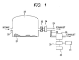
- Fig. 1 is a block diagram illustrating the constitution of the whole apparatus necessary for carrying out the invention. As a typical example, the case of monitoring the concentrations of chemical agents released into the atmosphere on the occasion of digging up and recovering an abandoned chemical weapon is described.
- a tent 22 is set up in the vicinity of the digging up/recovering site 21. It is necessary to maintain the inside of the tent 22 at a negative pressure relative to the outside open air so that even when a chemical agent gas is generated within the inside, the gas may be prevented from leaking out of the tent. For that purpose, the air inside the tent 22 is always exhausted by an exhaust fan 23, while the open air is fed to the tent inside through an air inlet 33.
- the pressure within the tent 22 is determined by the conductance balance between air intake and air exhaustion.
- the exhaust pipe 25 for exhausting the air in the tent 22 to the outside is provided with a chemical agent removing filter 24 such as an active carbon filter and, thus, even if a chemical agent gas is generated in the process of working inside the tent 22, the leakage of the gas to the outside can be prevented.
- a part of the gas in the exhaust pipe 25 is branched by an introduction pipeline 28 and introduced into a chemical agent detector 29.
- the detection signal from the chemical agent detector 29 is sent to a data processor 30.
- the data processor 30 refers to a database 31 storing chemical agent-derived signals, calculates the chemical agent concentration from the relation between the signal detected by the chemical agent detector 29 and the chemical agent concentration (namely sensitivity), and causes the chemical agent concentration to be displayed in a display section 32.
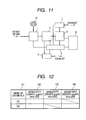
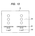
- the information stored in the database 31 includes substance names 101, sites of signals appearing on a mass spectrum (m/z) and sensitivities 102, 103 and 104 at respective m/z values, among others, as shown, for example, in Fig. 12. It is recommended that the display section 32 be provided with alarms 203, for instance, for judging the degree of danger with ease in addition to substance names 201 and concentrations thereof 202, as shown in Fig. 13.
- color coding is made on the alarm 32, for example if a blue lamp for indicating a level below the control level, a yellow lamp for indicating a level exceeding the control level, or a red lamp for indicating a level greatly exceeding the control level and needing emergent worker evacuation is lighted according to the situation, the situation can be recognized with ease. It is further recommended that such functions as sounding an alarm or/and notifying an administrator about the danger through wire or by radio be provided.
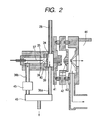
- Fig. 2 shows the ion source section of the chemical agent detector which utilizes the technique of atmospheric pressure chemical ionization mass spectrometry.
- a gas introduced through the introduction pipeline 28 is once introduced into an ion drift section 34.
- This ion drift section 34 is in an approximately atmospheric pressure condition.
- a part of the gas introduced into the ion drift section 34 is introduced into a corona discharge section 35 and the remainder is discharged out of the ion source via an exhaust pipeline 36a.
- the gas introduced into the corona discharge section 35 is introduced into a corona discharge region 38 formed in the vicinity of the extreme end of a needle electrode 37 by application of a high voltage to the needle electrode 37 and is ionized.
- a gas is introduced into the corona discharge region 38 in the direction approximately opposing the current of drifting ions from the needle electrode toward a counter electrode 39.
- the ions formed are introduced into the ion drift section 34 through the opening 40 of a counter electrode 39 under the influence of an electric field. On this occasion, it is possible to drift the ions and efficiently introduce them into a first narrow orifice 41.
- the ions introduced from the first narrow orifice 41 are introduced into a vacuum section 44 through a second narrow office 42 and a third narrow orifice 43.
- the flow rate control of the gas flowing into the corona discharge section 35 is important for high-sensitivity and stable detection.
- a flow rate controlling section 45 is preferably provided in an exhaust gas pipeline 36b.
- the ion drift section 34, corona discharge section 35 and introduction pipeline 28, among others, are preferably heated by means of heaters (not shown) or the like from the viewpoint of preventing the sample from being adsorbed thereon.
- the rates of flow of the gas passing through the introduction pipeline 28 and exhaust pipeline 36a can be determined by the capacity of a suction pump 46, for example a diaphragm pump, and the pipeline conductance, it is also possible to provide a control device such as a flow rate controller 45 in the introduction pipeline 28 and/or exhaust pipeline 36a.
- Fig. 3 is a figure showing the apparatus constitution of the mass spectrometry section of the chemical agent detector. It shows an example of the use of a quadrupole ion trap mass spectrometer (hereinafter referred to as "ion trap mass spectrometer") as the mass spectrometer.
- An ion source 47 having the structure shown in Fig. 2 is connected with an introduction pipeline 28 and exhaust pipelines 36a and 36b. Components contained in the gas introduced into the ion source are partly ionized.
- the ions formed by means of the ion source and the gas introduced into the ion source are partly taken into a vacuum section 44 evacuated by a vacuum pump 48 via the first narrow orifice 41, second narrow orifice 42 and third narrow orifice 43.
- These narrow orifices have a diameter of about 0.3 mm and the electrodes having the narrow orifices are heated to about 100°C-300°C by heaters (not shown).
- the gas portion not introduced into the first narrow orifice is exhausted to the outside via the exhaustion pipes 36a and 36b by means of a pump.
- differential exhaustion sections 49a and 49b which are exhausted by a roughing vacuum pump 50.
- a roughing vacuum pump 50 is a rotary pump, scroll pump or mechanical booster pump, for instance.
- a voltage can be applied to the electrodes having the narrow orifices 41, 42 and 43 by a power source (not shown) so that the ion permeability of the differential exhaustion sections 49a and 49b may be improved and, at the same time, cluster ions formed by adiabatic expansion may be cleaved by collision with remaining molecules.
- a power source not shown
- a scroll pump with a pumping speed of 900 liters/minute was used as the roughing vacuum pump 50, and a turbo-molecular pump with a pumping speed of 300 liters/second as the vacuum pump 48 for evacuating the vacuum section 44.
- the roughing vacuum pump 50 also serves as a pump for exhausting the back pressure side of the turbo-molecular pump.
- the pressure between the second narrow orifice 42 and the third narrow orifice 43 is about 100 pascals. It is also possible to remove the electrode having the second narrow orifice 42 to form a differential exhaustion section constituted of two narrow orifices, namely the first narrow orifice 41 and third narrow orifice 43.
- the ions formed after passage through the third narrow orifice 43 are converged by a convergent lens 51.
- An einzel lens consisting of three electrodes, for instance, is generally used as the convergent lens 51.
- the ions further pass through a slit electrode 52.
- the structure is such that the ions that have passed through the third narrow orifice 43 are focused on the opening section of the slit electrode 52 by the convergent lens 51 and pass therethrough, while the neutral and other particles not focused collide with this slit portion and hardly enter the mass spectrometer side.
- the ions that have passed through the slit electrode 52 are deflected and focused by means of a double cylinder type deflector 55 consisting of an inner cylindrical electrode 53 and an outer cylindrical electrode 54 each having a large number of openings.
- the double cylinder type deflector 55 the deflection and focusing are realized by utilizing the electric field of the outer cylindrical electrode as spreading from the opening of the inner cylindrical electrode. This is described in detail in JP 07 (1995) -85834 .
- the ions that have passed through the double cylinder type deflector 55 are introduced into the ion trap mass spectrometer constituted of a ring electrode 56 and end gap electrodes 57a and 57b.
- a gate electrode 58 for controlling the timing of injection of the ions into the mass spectrometer.
- Flange electrodes 59a and 59b are provided for preventing quartz rings 60a and 60b, which hold the ring electrode 56 and end cap electrodes 57a and 57b, from being charged by ions arriving at the quartz rings 60a and 60b.
- Helium is fed from a helium gas feeding pipe (not shown) to the ion trap mass spectrometer inside and the pressure therein is maintained at about 0.1 pascal.
- the ion trap mass spectrometer is controlled by a mass spectrometer controlling section (not shown).
- the ions introduced into the mass spectrometer collide with the helium gas and lose their energy and are entrapped by an alternating electric field.
- the ions entrapped are discharged out of the ion trap mass spectrometer according to the m/z values of the ions and, after passage through an ion outlet lens 61, are detected by a detector 62.
- the signals detected are amplified by an amplifier 63 and then processed in a data processor 64.
- the ion trap mass spectrometer has a characteristic feature in that it entraps ions within the inside thereof (in a space surrounded by the ring electrode 56 and the end gap electrodes 57a and 57b) , so that even when the concentration of the detection target substance(s) is low and the amount of ions formed is small, the ions can be detected by prolonging the ion introduction time. Therefore, even when the sample concentration is low, ions can be concentrated at a high rate in the ion trap mass spectrometer and thus the sample pretreatment (e.g. concentration) can be very much simplified.
- a mass spectrum of DC as obtained in the chemical agent monitoring apparatus described above referring to Figs. 1-3 is shown in Fig. 4, and a mass spectrum of DA as obtained in the same manner is shown in Fig. 5.
- the positive ionization mode was used.
- a hexane solution of DC or DA was injected into the introduction pipeline 28.
- the size of injection of the reagent was about 20 ng in each case.
- DC is a chemical substance having the following structure:
- DA is a chemical substance having the following structure
- DA has a molecular weight of 264
- the signals shown in Fig. 4 and Fig. 5 were obtained instantaneously (within 1 second) and thus it was found that the DC and DA gases can be instantaneously detected upon arrival thereof at the ion source when the technique of atmospheric pressure chemical ionization mass spectrometry is used in the positive ionization mode.
- the time required for each measurement was about 2 seconds. Therefore, once an alarm threshold value is determined by obtaining data for the air at the site of measurement and determining the standard deviation ⁇ of the background, it is possible to immediately detect DC in case of leakage thereof and give an alarm. Since the DC concentration can be easily determined from the calibration curve and signal intensity, it is possible to measure the DC concentration, even when it is very low, almost on the real time basis in accordance with the present invention.
- each sample solution was injected into the introduction pipeline 28.
- each arrow indicates the timing of sample solution injection.
- the narrow orifice-forming electrodes and pipelines were maintained at a temperature of 120°C and the corona discharge current was set at 10 microamperes.
- the intensity ratio was almost constant.
- a solution of a mixture of DC and DA was prepared and injected into the introduction pipeline 28.
- a flow for estimating the DA concentration is shown in Fig. 14.
- the concentrations of DC or/and DA at very low levels can be known rapidly and exactly and, therefore, environmental leakage monitoring becomes possible in abandoned chemical weapon treatment or the like and the invention can thus contribute to the safety of workers and nearby residents, among others.
Landscapes
- Chemical & Material Sciences (AREA)
- Analytical Chemistry (AREA)
- Other Investigation Or Analysis Of Materials By Electrical Means (AREA)
Abstract
A gas monitoring apparatus capable of real-time detection of a kind of chemical warfare agent, namely diphenylcyanoarsine (DC) and/or diphenylchloroarsine (DA). Atmospheric pressure chemical ionization mass spectrometry is carried out in the positive ionization mode, the total amount of DC and DA is determined from the intensity of an ion common to DC and DA, the DC concentration is determined from the intensity of an ion specific to DC, and the difference between them is regarded as the DA concentration.
Description
- The present application claims priority from
Japanese application JP 2006-237892 filed on September 1, 2006 - The present invention belongs to the field of mass spectrometry technology and, more particularly, relates to a gas monitoring apparatus for measuring the concentration (s) of a chemical warfare agent(s) in the atmosphere using a mass spectrometer and displaying the same.
- The threat of terrorism is increasing all over the world. As for chemical terrorism using a chemical warfare agent (hereinafter referred to as "chemical agent"), in particular, the production of such a chemical agent is easier as compared with nuclear weapons and, once really committed, it causes a serious damage, so that every country is taking strict precautions against it. In Japan, too, a chemical agent was misused in the Matsumoto and Subway sarin gas incidents, among others, and it is urgent that measures be taken against chemical agents. Further, it has become evident that chemical weapons estimably produced by the old Japanese army during the wartime are buried in China and in Japan; reportedly, chemical agents allowed to leak out into the environment during construction work, for instance, caused health damages in some instances. It is required that abandoned chemical weapons and chemical agents retained therein be dug up, recovered and rendered harmless safely and promptly.
- In case of actual use or leakage of a chemical agent, it is necessary to immediately know the chemical agent species and the concentration thereof in the atmosphere and utilize the information obtained in inhabitant evacuation, treatment and decontamination. Therefore, a chemical agent detector utilizing the technology of mass spectrometric analysis, which is known as a method excellent in speed, sensitivity and selectivity among various analytical methods, has been proposed (
JP 2004-158296 A JP 2004-286648 A sample introduction section 1, anionization section 2, amass spectrometry section 3, acontrol section 4, asuction pump 5, acomputer 6 for measurement and processing and avacuum pump 7. Asample 16 introduced into thesample introduction section 1 is heated and vaporized. The sample, now gaseous, is led to theionization section 2 by means of thesuction pump 5. The sample introduced into theionization section 2 is sent to and ionized in a corona discharge region. The ions formed are led to themass spectrometry section 3 for mass spectrometric analysis. The results of the mass analysis are processed by the measurement/processingcomputer 6 for displaying. When the results obtained show the characteristic features of the results of measurement of a chemical agent, the chemical agent is regarded as having been detected. - As a gas monitoring apparatus which utilizes atmospheric pressure chemical ionization mass spectrometry, an exhaust gas monitoring apparatus is disclosed in
JP 2000-162189 A JP 2005-274566 A - Detailed investigations have so far been made concerning the methods of analyzing and detecting lethal chemical agents such as sarin. On the other hand, diphenylcyanoarsine (hereinafter referred to as DC) and diphenylchloroarsine (hereinafter referred to as DA) developed for suppressing riots and called sneezing agents or emetics have not been produced since the Second World War and, therefore, methods of analyzing or detecting these agents DC and DA have seldom been investigated. However, it is to be worried that, in the treatment of abandoned chemical weapons, health damage and environmental pollution may be caused by those DC and DA produced in the past.
-
JP 2005-274565 A - The first problem is the detection time problem. The above technology includes the steps of collection, by suction, of a sample gas → derivatization treatment → analysis by a gas chromatograph and, therefore, it seems that scores of minutes is required for obtaining the results. Since, however, once a person is exposed to a chemical agent, the effect thereof is produced in an instant, it is necessary, on the occasion of chemical agent leakage, to issue a warning as soon as possible. Thus, an apparatus which can detect DC and DA simultaneously without needing any complicated procedure has been demanded.
- The second problem is the sensitivity problem. Upon derivatization treatment, as in the above technology, DC and DA are converted to one and the same substance. Therefore, the total amount of DC and DA can be determined but a problem remains, namely the respective concentrations of DC and DA cannot be known. While no detailed toxic data for DC and DA are available, the median lethal dose (concentration which is lethal to half of persons exposed to that concentration for 1 minute) of DC is estimated to be 1000-10000 mg-min/m3 and that of DA to be about 15000 mg-min/m3. Thus, DC is considered to be more toxic than DA. Therefore, in case a worker engaged in abandoned chemical agent treatment should be exposed to DC and/or DA, it is important, in deciding the method of treatment, among others, to know the individual concentrations.
- For such reasons as mentioned above, a chemical agent monitoring apparatus by which the respective concentrations of DC and DA can be known without delay has been desired.
- The present invention provides a chemical agent monitoring apparatus capable of determining the respective concentrations of DC and DA simultaneously by utilizing the technology of atmospheric pressure chemical ionization mass spectrometry.
- More specifically, the gas monitoring apparatus of the invention comprises a gas introduction section for introducing a sample gas, an ion source for ionizing components contained in the sample gas by corona discharge, a mass spectrometer for analyzing the ions formed by the ion source for m/z (value resulting from division of the mass by the valence), an operation section for calculating the concentrations of measurement target substances contained in the sample gas based on the ion intensity data obtained by the mass spectrometer, and a display section for displaying the operation results obtained in the operation section, in which apparatus the sum total concentration of diphenylcyanoarsine and diphenylchloroarsine are calculated from a signal common to diphenylcyanoarsine and diphenylchloroarsine included in the measurement target substances, the concentration of diphenylcyanoarsine is calculated from a signal specific to diphenylcyanoarsine and the concentration of diphenylchloroarsine is calculated from the difference between the sum total concentration and the concentration of diphenylcyanoarsine. On that occasion, the m/z=229 ion intensity signal is preferably used as the signal common to diphenylcyanoarsine and diphenylchloroarsine, and the m/z=256 ion intensity signal as the signal specific to diphenylcyanoarsine.
- If a chemical agent leakage accident should occur during abandoned chemical weapon treatment, the exact concentrations of DC and DA can be known in an instant in accordance with the present invention. Therefore, the information about the chemical agent species leaked out and the concentrations thereof, which are important in carrying out evacuation and leading of workers and nearby residents, treatment thereof and decontamination, among others, can be promptly provided. Since the respective concentrations of DC and DA, which differ in toxicity, can be determined, evacuation, treatment, decontamination and like dealing with the aftermath can be carried out appropriately.
-
- Fig. 1 is a block diagram illustrating the constitution of the whole apparatus necessary for carrying out the invention;
- Fig. 2 is a figure showing the ion source section of the chemical agent detector;
- Fig. 3 is a figure showing the mass spectrometry section of the chemical agent detector;
- Fig. 4 is a figure showing a mass spectrum of DC;
- Fig. 5 is a figure showing a mass spectrum of DA;
- Fig. 6 is a figure showing the signals detected in tandem mass spectrometry of DC;
- Fig. 7 is a figure showing a calibration curve for DA in tandem mass spectrometry;
- Fig. 8 is a figure showing the signals detected in mass spectrometry of DC;
- Fig. 9 is a figure showing the signals detected in mass spectrometry of DA;
- Fig. 10 is a figure showing the signals detected in mass spectrometry of a mixed sample containing DC and DA;
- Fig. 11 is a figure schematically illustrating a prior art chemical agent detector;
- Fig. 12 is a figure illustrating the contents of a database;
- Fig. 13 is a figure showing the display section; and
- Fig. 14 is a figure showing a flowchart for determining the required concentrations.
- In the following, referring to the drawings, certain modes of embodiment of the present invention are described in detail.
- Fig. 1 is a block diagram illustrating the constitution of the whole apparatus necessary for carrying out the invention. As a typical example, the case of monitoring the concentrations of chemical agents released into the atmosphere on the occasion of digging up and recovering an abandoned chemical weapon is described.
- On the occasion of digging up and recovering, among others, of an abandoned chemical weapon, there is the risk of contamination of the soil by a chemical agent and, in addition, there is the possibility of an undiscovered chemical weapon, for instance, being contained in the soil and, therefore, careful management is required. Thus, a
tent 22 is set up in the vicinity of the digging up/recoveringsite 21. It is necessary to maintain the inside of thetent 22 at a negative pressure relative to the outside open air so that even when a chemical agent gas is generated within the inside, the gas may be prevented from leaking out of the tent. For that purpose, the air inside thetent 22 is always exhausted by anexhaust fan 23, while the open air is fed to the tent inside through anair inlet 33. The pressure within thetent 22 is determined by the conductance balance between air intake and air exhaustion. The exhaust pipe 25 for exhausting the air in thetent 22 to the outside is provided with a chemicalagent removing filter 24 such as an active carbon filter and, thus, even if a chemical agent gas is generated in the process of working inside thetent 22, the leakage of the gas to the outside can be prevented. However, in preparation for a filter trouble, for example filter breakthrough, a part of the gas in the exhaust pipe 25 is branched by anintroduction pipeline 28 and introduced into achemical agent detector 29. The detection signal from thechemical agent detector 29 is sent to adata processor 30. Thedata processor 30 refers to adatabase 31 storing chemical agent-derived signals, calculates the chemical agent concentration from the relation between the signal detected by thechemical agent detector 29 and the chemical agent concentration (namely sensitivity), and causes the chemical agent concentration to be displayed in adisplay section 32. - The information stored in the
database 31 includessubstance names 101, sites of signals appearing on a mass spectrum (m/z) andsensitivities display section 32 be provided withalarms 203, for instance, for judging the degree of danger with ease in addition tosubstance names 201 and concentrations thereof 202, as shown in Fig. 13. If color coding is made on thealarm 32, for example if a blue lamp for indicating a level below the control level, a yellow lamp for indicating a level exceeding the control level, or a red lamp for indicating a level greatly exceeding the control level and needing emergent worker evacuation is lighted according to the situation, the situation can be recognized with ease. It is further recommended that such functions as sounding an alarm or/and notifying an administrator about the danger through wire or by radio be provided. - Fig. 2 shows the ion source section of the chemical agent detector which utilizes the technique of atmospheric pressure chemical ionization mass spectrometry. A gas introduced through the
introduction pipeline 28 is once introduced into anion drift section 34. Thision drift section 34 is in an approximately atmospheric pressure condition. A part of the gas introduced into theion drift section 34 is introduced into acorona discharge section 35 and the remainder is discharged out of the ion source via anexhaust pipeline 36a. The gas introduced into thecorona discharge section 35 is introduced into acorona discharge region 38 formed in the vicinity of the extreme end of aneedle electrode 37 by application of a high voltage to theneedle electrode 37 and is ionized. On that occasion, a gas is introduced into thecorona discharge region 38 in the direction approximately opposing the current of drifting ions from the needle electrode toward acounter electrode 39. - The ions formed are introduced into the
ion drift section 34 through theopening 40 of acounter electrode 39 under the influence of an electric field. On this occasion, it is possible to drift the ions and efficiently introduce them into a firstnarrow orifice 41. The ions introduced from the firstnarrow orifice 41 are introduced into avacuum section 44 through a secondnarrow office 42 and a thirdnarrow orifice 43. The flow rate control of the gas flowing into thecorona discharge section 35 is important for high-sensitivity and stable detection. For this purpose, a flowrate controlling section 45 is preferably provided in anexhaust gas pipeline 36b. Theion drift section 34,corona discharge section 35 andintroduction pipeline 28, among others, are preferably heated by means of heaters (not shown) or the like from the viewpoint of preventing the sample from being adsorbed thereon. While the rates of flow of the gas passing through theintroduction pipeline 28 andexhaust pipeline 36a can be determined by the capacity of asuction pump 46, for example a diaphragm pump, and the pipeline conductance, it is also possible to provide a control device such as aflow rate controller 45 in theintroduction pipeline 28 and/orexhaust pipeline 36a. By providing thesuction pump 46 downstream from the ion formation section (namely thecorona discharge section 35 in the constitution illustrated) in the direction of gas flow, it becomes possible to reduce the influence of contamination (e.g. adsorption of the sample) of the inside of thesuction pump 46 on the measurement. - Fig. 3 is a figure showing the apparatus constitution of the mass spectrometry section of the chemical agent detector. It shows an example of the use of a quadrupole ion trap mass spectrometer (hereinafter referred to as "ion trap mass spectrometer") as the mass spectrometer. An
ion source 47 having the structure shown in Fig. 2 is connected with anintroduction pipeline 28 andexhaust pipelines vacuum section 44 evacuated by avacuum pump 48 via the firstnarrow orifice 41, secondnarrow orifice 42 and thirdnarrow orifice 43. These narrow orifices have a diameter of about 0.3 mm and the electrodes having the narrow orifices are heated to about 100°C-300°C by heaters (not shown). The gas portion not introduced into the first narrow orifice is exhausted to the outside via theexhaustion pipes - Among the electrodes respectively having the
narrow orifices differential exhaustion sections roughing vacuum pump 50. Generally used as theroughing vacuum pump 50 is a rotary pump, scroll pump or mechanical booster pump, for instance. A voltage can be applied to the electrodes having thenarrow orifices differential exhaustion sections roughing vacuum pump 50, and a turbo-molecular pump with a pumping speed of 300 liters/second as thevacuum pump 48 for evacuating thevacuum section 44. Theroughing vacuum pump 50 also serves as a pump for exhausting the back pressure side of the turbo-molecular pump. The pressure between the secondnarrow orifice 42 and the thirdnarrow orifice 43 is about 100 pascals. It is also possible to remove the electrode having the secondnarrow orifice 42 to form a differential exhaustion section constituted of two narrow orifices, namely the firstnarrow orifice 41 and thirdnarrow orifice 43. In this case, however, the gas inflow increases as compared with the case mentioned above, so that contrivances are required, for example for increasing the pumping speed or/and increasing the distance between the narrow nozzles. In this case, too, it is important to apply a voltage between both the narrow orifices. - The ions formed after passage through the third
narrow orifice 43 are converged by a convergent lens 51. An einzel lens consisting of three electrodes, for instance, is generally used as the convergent lens 51. The ions further pass through a slit electrode 52. The structure is such that the ions that have passed through the thirdnarrow orifice 43 are focused on the opening section of the slit electrode 52 by the convergent lens 51 and pass therethrough, while the neutral and other particles not focused collide with this slit portion and hardly enter the mass spectrometer side. The ions that have passed through the slit electrode 52 are deflected and focused by means of a doublecylinder type deflector 55 consisting of an innercylindrical electrode 53 and an outercylindrical electrode 54 each having a large number of openings. In the doublecylinder type deflector 55, the deflection and focusing are realized by utilizing the electric field of the outer cylindrical electrode as spreading from the opening of the inner cylindrical electrode. This is described in detail inJP 07 (1995) -85834 cylinder type deflector 55 are introduced into the ion trap mass spectrometer constituted of aring electrode 56 andend gap electrodes gate electrode 58 for controlling the timing of injection of the ions into the mass spectrometer.Flange electrodes quartz rings ring electrode 56 andend cap electrodes - The ions introduced into the mass spectrometer collide with the helium gas and lose their energy and are entrapped by an alternating electric field. Upon scanning with a high frequency voltage applied upon the
ring electrode 56 andend gap electrodes ion outlet lens 61, are detected by adetector 62. The signals detected are amplified by anamplifier 63 and then processed in adata processor 64. The ion trap mass spectrometer has a characteristic feature in that it entraps ions within the inside thereof (in a space surrounded by thering electrode 56 and theend gap electrodes - Now, a mass spectrum of DC as obtained in the chemical agent monitoring apparatus described above referring to Figs. 1-3 is shown in Fig. 4, and a mass spectrum of DA as obtained in the same manner is shown in Fig. 5. In ionization, the positive ionization mode was used. In this measurement, a hexane solution of DC or DA was injected into the
introduction pipeline 28. The size of injection of the reagent was about 20 ng in each case. - In the positive atmospheric pressure chemical ionization mass spectrometry, water vapor is involved in the main ionization processes. First, nitrogen molecules are ionized by corona discharge and the nitrogen molecule ions are immediately ionize water vapor in the atmosphere to form hydronium ions (H3O+). Many chemical substances are ionized by the chemical reaction with these hydronium ions.
- Fig. 4 is first explained. DC is a chemical substance having the following structure:

- The molecular weight of DC is 255 and the ions observed upon atmospheric pressure chemical ionization are always monovalent and, therefore, the signal observed at m/z = 256 is considered to be a pseudomolecular ion resulting from addition of a proton to DC as formed by the reaction:
DC + H3O+ → (DC+H)+ + H2O (1)
The ion observed at m/z = 229 is considered to be a decomposition product ion resulting from elimination of CN from DC as formed by the reaction:
DC + H3O+ → (DC-CN)+ + HCN + H2O (2)
- Now, Fig. 5 is explained. DA is a chemical substance having the following structure

- Since DA has a molecular weight of 264, the signal observed at m/z = 265 is considered to be a pseudomolecular ion resulting from addition of a proton to DA as formed by the reaction:
DA + H3O+ → (DA+H) + + H2O (3)
The ion observed at m/z = 229 is considered to be a decomposition product ion resulting from elimination of C1 from DA as formed by the reaction:
DA + H3O+ → (DC-Cl) + + HCl + H2O (4)
- Upon injection of the sample solutions, the signals shown in Fig. 4 and Fig. 5 were obtained instantaneously (within 1 second) and thus it was found that the DC and DA gases can be instantaneously detected upon arrival thereof at the ion source when the technique of atmospheric pressure chemical ionization mass spectrometry is used in the positive ionization mode. In particular, the decomposition product ion at m/z = 229 shows a high intensity, and this experiment revealed for the first time that DC and DA can be measured very speedily and with good sensitivity by measuring this signal. Any complicated procedure as in the prior art technologies is not required and, even when signals are accumulated for increasing the reliability, the results can be obtained in several seconds following gas suction and, therefore, in case of leakage of DC and/or DA, it is now possible to issue a warning promptly.
- For determining the individual concentrations of DC and DA, it is enough to measure the respective specific signals, namely the m/z=256 and m/z=265 signals. As is evident from Fig. 4 and Fig. 5, the m/z=256 and m/z=265 signals are weak and, therefore, tandem mass spectrometry is effective in determining the individual concentrations of DC and DA at very low levels. Tandem mass spectrometry is well known in the field of analysis and the description of the technique thereof is omitted. It can reduce chemical noises appearing on the mass spectrum and makes it possible to detect weak signals as well. In an experiment, when tandem mass spectrometry was carried out with the DC-derived m/z = 256 ion as a precursor ion, the dissociation of m/z = 256 → 229 was observed. This is considered to be the result of occurrence of the reaction:
(DC+H)+ → (DC-CN)+ + HCN (5).
Then, when tandem mass spectrometry was carried out with the DA-derived m/z=265 ion as a precursor ion, the dissociation of m/z = 265 → 229 was observed. This is considered to be the result of occurrence of the reaction:
(DA+H)+ → (DA-Cl)+ + HCl (6).
- Now, the results of an investigation concerning the lower DC detection limit in m/z = 256 → 229 tandem mass spectrometry using the apparatus disclosed herein are described. In this experiment, a 10-liter stainless steel container was used. A hexane solution containing DC dissolved therein was poured into the stainless container and a desired concentration of DC gas was generated by allowing evaporation, the container was then connected with the apparatus and the DC-due ion intensity was measured. Fig. 6 shows the ion intensities as found upon sucking the gas in various concentrations shown in the figure into the apparatus. After connection of the container, the gas in the container was diluted with the air drawn into the container from the outside and the gas concentration decreased and, as a result, the signal intensity decreased gradually. In view of the gas concentration changing during measurement in that manner, signals obtained during about 1 minute after connection of the container were averaged to give ion intensities at respective concentrations, which were used to construct a calibration curve (working curve). The calibration curve for DC is shown in Fig. 7. The results shown in Fig. 7 indicate that the sensitivity (gradient of the calibration curve) of the apparatus disclosed herein is 34000 counts/(µg/m3). On the other hand, when DC-free air was sucked in, the fluctuation in background signal (standard deviation σ) as determined by 100 measurements was 340 counts and, therefore, the lower detection limit for DC, when defined as 3σ, was about 0.03 µg/m3.
- In the above experiment, the time required for each measurement was about 2 seconds. Therefore, once an alarm threshold value is determined by obtaining data for the air at the site of measurement and determining the standard deviation σ of the background, it is possible to immediately detect DC in case of leakage thereof and give an alarm. Since the DC concentration can be easily determined from the calibration curve and signal intensity, it is possible to measure the DC concentration, even when it is very low, almost on the real time basis in accordance with the present invention.
- Then, the lower detection limit for DA in tandem mass spectrometry based on the m/z = 265 → 229 dissociation was determined in the same manner as in the above-mentioned case of DC and was found to be about 1 µg/m3. This is because DA is more readily decomposed as compared with DC. As is evident from comparison between Fig. 4 and Fig. 5, the m/z=265 ion intensity specific to DA is weaker than the m/z=256 ion intensity specific to DC. Therefore, in the case of DA, the m/z=265 → 229 ion intensity after tandem mass spectrometry is also weaker as compared with the m/z=256 → 229 signal in the case of DC. Accordingly, the measurement of DA at very low concentrations becomes more difficult.
- As described above, it was found, as a result of the experiments, that, in determining the DA concentration at a very low level, namely 1 µg/m3 or lower, on the real time basis, it is recommendable to calculate the total concentration of DC and DA based on a signal (e.g. m/z = 229) common to DC and DA, calculate the DC concentration from the m/z=256 → 229 signal specific to DC and calculate the DA concentration as the difference between both.
- For confirmation, the results of comparison of the m/z = 229, 256 and 265 signal intensities obtained from DA and DC are shown in Figs. 8-10. Like in the cases of Fig. 4 and Fig. 5, each sample solution was injected into the
introduction pipeline 28. In Figs. 8-10, each arrow indicates the timing of sample solution injection. In this measurement, the narrow orifice-forming electrodes and pipelines were maintained at a temperature of 120°C and the corona discharge current was set at 10 microamperes. - First, Fig. 8 shows the results of measurement of DC. Sample-due signals were detected at m/z = 229 and 256 but no signal was detected at 265. The area ratio between the m/z = 229 and 256 signals was calculated to be 5:1. Fig. 9 shows the results of measurement of DA. Sample-due signals were detected at m/z = 229 and 265 but no signal was detected at 256. The area ratio between the m/z = 229 and 265 signals was calculated to be 50:1.
- Since the m/z = 229 signal is due to a decomposition product, the intensity ratio between m/z = 229 and 256 or 265 varies when the measurement conditions, for example the temperature of the narrow orifice-forming electrodes or/and the discharge current in the corona discharge section, are changed. However, when repeated evaluations were made using one and the same apparatus under standardized measurement conditions, the intensity ratio was almost constant.
- Then, a solution of a mixture of DC and DA was prepared and injected into the
introduction pipeline 28. The results obtained are shown in Fig. 10. Signals were observed at all of m/z = 229, 256 and 265, and the area ratio among these signals was calculated to be 59:1.6:1. When the intensity of the m/z=256 signal specific to DC alone was multiplied by 5 and the intensity of the m/z=265 signal specific to DA alone was multiplied by 50, the sum of the both products was almost in agreement with the m/z=229 intensity observed. From the results shown in Fig. 10, it was confirmed that the m/z=229 intensity for a sample containing DC and DA in admixture is represented as the sum of the contribution of DC and the contribution of DA. - After all, at very low DA concentrations, it becomes difficult to detect the m/z=265 signal specific to DA. However, when the intensity ratios among the m/z=229, 256 and 265 signals are measured in advance using DC and DA and are used to create a database according to the apparatus and experimental conditions, the concentration of DA can be estimated from the intensities of the m/z=229 signal common to DC and DA and the m/z=256 signal specific to DC even if the m/z=265 signal cannot be obtained.
- A flow for estimating the DA concentration is shown in Fig. 14. First, a sample gas is subjected to mass analysis by atmospheric pressure chemical ionization mass spectrometry and the m/z=229, 256 and 265 signal intensities are measured (S11). Then, the DC concentration is calculated using the m/z=256 signal and a calibration curve (S12). Then, based on that DC concentration, the m/z=229 intensity due to DC is determined (S13). The m/z=229 signal intensity due to DA is calculated by subtracting the contribution of DC from the m/z=229 signal intensity actually measured (S14). Finally, the DA concentration is calculated based on the m/z=229 signal intensity due to DA using a calibration curve (S15).
- According to the invention, the concentrations of DC or/and DA at very low levels can be known rapidly and exactly and, therefore, environmental leakage monitoring becomes possible in abandoned chemical weapon treatment or the like and the invention can thus contribute to the safety of workers and nearby residents, among others.
Claims (5)
- A gas monitoring apparatus comprising:a gas introduction section for introducing a sample gas;an ion source for ionizing a component or components contained in the sample gas by corona discharge;a mass spectrometer for analyzing the ion or ions formed by the ion source for m/z;an operation section for calculating the concentration of diphenylcyanoarsine and/or diphenylchloroarsine contained in the sample gas based on the ion intensity data obtained by the mass spectrometer; anda display section for displaying the result or results obtained in the operation section,wherein said operation section calculates the sum total concentration of diphenylcyanoarsine and diphenylchloroarsine from a signal common to diphenylcyanoarsine and diphenylchloroarsine as obtained in said mass spectrometer, calculates the concentration of diphenylcyanoarsine from a signal specific to diphenylcyanoarsine and calculates the concentration of diphenylchloroarsine from the difference between said sum total concentration and said concentration of diphenylcyanoarsine.
- The gas monitoring apparatus according to Claim 1,
wherein said signal common to diphenylcyanoarsine and diphenylchloroarsine is the m/z=229 ion intensity signal and said signal specific to diphenylcyanoarsine is the m/z=256 ion intensity signal. - The gas monitoring apparatus according to Claim 2, comprising a storage section for storing the information concerning the sensitivity to diphenylcyanoarsine and to diphenylchloroarsine at the m/z=229 ion intensity signal, and the sensitivity to diphenylcyanoarsine at the m/z=256 ion intensity signal.
- A gas monitoring method, comprising the steps of:subjecting a sample gas to mass analysis utilizing the technique of atmospheric pressure chemical ionization mass spectrometry and measuring a signal common to diphenylcyanoarsine and diphenylchloroarsine and a signal specific to diphenylcyanoarsine;calculating the diphenylcyanoarsine concentration based on said signal specific to diphenylcyanoarsine;determining the diphenylcyanoarsine-due intensity out of the intensity of said signal common to diphenylcyanoarsine and diphenylchloroarsine based on the diphenylcyanoarsine concentration calculated in the above step;calculating the diphenylchloroarsine-due signal intensity by subtracting said diphenylcyanoarsine-due intensity from the intensity of said signal common to diphenylcyanoarsine and diphenylchloroarsine as measured; andcalculating the diphenylchloroarsine concentration based on said diphenylchloroarsine-due signal intensity out of the intensity of the signal common to diphenylcyanoarsine and diphenylchloroarsine as measured.
- The gas monitoring method according to Claim 4,
wherein said signal common to diphenylcyanoarsine and diphenylchloroarsine is the m/z=229 ion intensity signal and said signal specific to diphenylcyanoarsine is the m/z=256 ion intensity signal.
Applications Claiming Priority (1)
| Application Number | Priority Date | Filing Date | Title |
|---|---|---|---|
| JP2006237892A JP2008058238A (en) | 2006-09-01 | 2006-09-01 | Gas monitoring device and gas monitoring method |
Publications (1)
| Publication Number | Publication Date |
|---|---|
| EP1895566A2 true EP1895566A2 (en) | 2008-03-05 |
Family
ID=38950827
Family Applications (1)
| Application Number | Title | Priority Date | Filing Date |
|---|---|---|---|
| EP07001763A Withdrawn EP1895566A2 (en) | 2006-09-01 | 2007-01-26 | Gas monitoring apparatus and gas monitoring method |
Country Status (4)
| Country | Link |
|---|---|
| US (1) | US7663098B2 (en) |
| EP (1) | EP1895566A2 (en) |
| JP (1) | JP2008058238A (en) |
| CN (1) | CN101135668A (en) |
Cited By (1)
| Publication number | Priority date | Publication date | Assignee | Title |
|---|---|---|---|---|
| CN113447611A (en) * | 2021-05-20 | 2021-09-28 | 南京云联信息科技有限公司 | Gas detection early warning system and device based on industrial internet |
Families Citing this family (6)
| Publication number | Priority date | Publication date | Assignee | Title |
|---|---|---|---|---|
| JP4837056B2 (en) * | 2009-02-25 | 2011-12-14 | 警察庁科学警察研究所長 | Gas analyzer |
| CN102109491B (en) * | 2009-12-24 | 2013-03-27 | 同方威视技术股份有限公司 | Substance identification method of ion mobility spectrum (IMS) detection instrument based on ion diagram sequence |
| US9099286B2 (en) * | 2012-12-31 | 2015-08-04 | 908 Devices Inc. | Compact mass spectrometer |
| WO2014171378A1 (en) * | 2013-04-19 | 2014-10-23 | 株式会社島津製作所 | Mass spectroscopy device |
| CN104199433A (en) * | 2014-09-26 | 2014-12-10 | 胡景宗 | Centralized controlling auxiliary pre-warning system in heat-engine plant |
| KR20180137516A (en) | 2016-04-15 | 2018-12-27 | 예일 유니버시티 | Systems, apparatus and methods for monitoring organic compounds in a gaseous environment |
Family Cites Families (12)
| Publication number | Priority date | Publication date | Assignee | Title |
|---|---|---|---|---|
| JPS5166894A (en) * | 1974-09-09 | 1976-06-09 | Denki Kagaku Keiki Kk | Taikichu no tankasuisonodosokuteihoshiki |
| JPS5916665B2 (en) * | 1977-04-23 | 1984-04-17 | 株式会社堀場製作所 | Hydrocarbon measuring device |
| JPS5984467A (en) * | 1982-11-06 | 1984-05-16 | Mitsubishi Electric Corp | Monolithic infrared ray charge transfer element |
| JP3876554B2 (en) * | 1998-11-25 | 2007-01-31 | 株式会社日立製作所 | Method and apparatus for monitoring chemical substance and combustion furnace using the same |
| US6338266B1 (en) * | 2000-04-05 | 2002-01-15 | Industrial Scientific Corporation | Method of identifying a gas and associated apparatus |
| US20020172967A1 (en) * | 2001-02-13 | 2002-11-21 | Gadek Thomas R. | Identification of non-covalent complexes by mass spectrometry |
| AU2003281805A1 (en) * | 2002-07-18 | 2004-02-23 | The Johns Hopkins University | Combined chemical/biological agent detection system and method utilizing mass spectrometry |
| US6822223B2 (en) * | 2002-08-29 | 2004-11-23 | Siemens Energy & Automation, Inc. | Method, system and device for performing quantitative analysis using an FTMS |
| JP3787116B2 (en) * | 2002-11-06 | 2006-06-21 | 株式会社日立製作所 | How to detect chemical agents |
| JP4303499B2 (en) * | 2003-03-24 | 2009-07-29 | 株式会社日立ハイテクコントロールシステムズ | Chemical agent detection device |
| JP2005274565A (en) * | 2004-02-27 | 2005-10-06 | Kobelco Kaken:Kk | Analysis method for organoarsenic chemical agent in air and apparatus for it |
| JP4418721B2 (en) * | 2004-08-20 | 2010-02-24 | 株式会社堀場製作所 | Nitrogen compound analyzer |
-
2006
- 2006-09-01 JP JP2006237892A patent/JP2008058238A/en active Pending
-
2007
- 2007-01-26 EP EP07001763A patent/EP1895566A2/en not_active Withdrawn
- 2007-02-09 US US11/704,351 patent/US7663098B2/en not_active Expired - Fee Related
- 2007-02-16 CN CN200710078911.6A patent/CN101135668A/en active Pending
Cited By (2)
| Publication number | Priority date | Publication date | Assignee | Title |
|---|---|---|---|---|
| CN113447611A (en) * | 2021-05-20 | 2021-09-28 | 南京云联信息科技有限公司 | Gas detection early warning system and device based on industrial internet |
| CN113447611B (en) * | 2021-05-20 | 2024-01-26 | 南京云联信息科技有限公司 | A gas detection and early warning system and device based on industrial Internet |
Also Published As
| Publication number | Publication date |
|---|---|
| US20080054172A1 (en) | 2008-03-06 |
| CN101135668A (en) | 2008-03-05 |
| JP2008058238A (en) | 2008-03-13 |
| US7663098B2 (en) | 2010-02-16 |
Similar Documents
| Publication | Publication Date | Title |
|---|---|---|
| US7829848B2 (en) | Gas monitoring apparatus | |
| US7663098B2 (en) | Gas monitoring apparatus and gas monitoring method | |
| JP3660279B2 (en) | Sample ionizer and mass spectrometer | |
| US6838664B2 (en) | Mass spectrometer, mass spectrometry, and monitoring system | |
| Mulligan et al. | Direct monitoring of toxic compounds in air using a portable mass spectrometer | |
| US8188444B2 (en) | Analytic spectrometers with non-radioactive electron sources | |
| JP4303499B2 (en) | Chemical agent detection device | |
| US7820962B2 (en) | Detection systems and dopants | |
| Wolf et al. | Direct gas-phase detection of nerve and blister warfare agents utilizing active capillary plasma ionization mass spectrometry | |
| Urabe et al. | Development of portable mass spectrometer with electron cyclotron resonance ion source for detection of chemical warfare agents in air | |
| Li et al. | Direct detection of chemical warfare agent simulants in soil by thermal desorption-low temperature plasma-mass spectrometry | |
| CN107195529B (en) | Ionization method and device based on excited proton electron cooperative transfer reaction | |
| US6943343B2 (en) | Chemical agent detection apparatus and method | |
| JP2001351569A (en) | Online monitoring device for gas measurement | |
| JP4054493B2 (en) | Ion source | |
| Ringer | Detection of nerve agents using proton transfer reaction mass spectrometry with ammonia as reagent gas | |
| CN210604501U (en) | Chemical gas trace detector | |
| JP4291398B2 (en) | Mass spectrometer and dangerous substance detection device | |
| JP4062341B2 (en) | Ionization mass spectrometer, analysis method, and measurement system using the same | |
| JP4197676B2 (en) | Monitoring system | |
| JP2004171859A (en) | Quadrupole mass spectrometer | |
| Hoffland et al. | Ion Mobility Spectrometry as a Field Screening Technique. | |
| JP2009047710A (en) | Detection method of chemical | |
| McLuckey et al. | Explosives detection with an ion trap mass spectrometer |
Legal Events
| Date | Code | Title | Description |
|---|---|---|---|
| PUAI | Public reference made under article 153(3) epc to a published international application that has entered the european phase |
Free format text: ORIGINAL CODE: 0009012 |
|
| AK | Designated contracting states |
Kind code of ref document: A2 Designated state(s): AT BE BG CH CY CZ DE DK EE ES FI FR GB GR HU IE IS IT LI LT LU LV MC NL PL PT RO SE SI SK TR |
|
| AX | Request for extension of the european patent |
Extension state: AL BA HR MK YU |
|
| 17P | Request for examination filed |
Effective date: 20080331 |
|
| STAA | Information on the status of an ep patent application or granted ep patent |
Free format text: STATUS: THE APPLICATION HAS BEEN WITHDRAWN |
|
| 18W | Application withdrawn |
Effective date: 20100604 |