EP1895557A1 - Input device - Google Patents
Input device Download PDFInfo
- Publication number
- EP1895557A1 EP1895557A1 EP07253386A EP07253386A EP1895557A1 EP 1895557 A1 EP1895557 A1 EP 1895557A1 EP 07253386 A EP07253386 A EP 07253386A EP 07253386 A EP07253386 A EP 07253386A EP 1895557 A1 EP1895557 A1 EP 1895557A1
- Authority
- EP
- European Patent Office
- Prior art keywords
- operating member
- contacting point
- input device
- pair
- parts
- Prior art date
- Legal status (The legal status is an assumption and is not a legal conclusion. Google has not performed a legal analysis and makes no representation as to the accuracy of the status listed.)
- Granted
Links
- 229910000679 solder Inorganic materials 0.000 claims abstract description 48
- 230000007935 neutral effect Effects 0.000 claims abstract description 14
- 230000005611 electricity Effects 0.000 claims abstract description 10
- 230000003068 static effect Effects 0.000 claims abstract description 10
- 238000007599 discharging Methods 0.000 claims description 2
- 238000005476 soldering Methods 0.000 claims 1
- 239000002184 metal Substances 0.000 abstract description 7
- 238000000034 method Methods 0.000 description 10
- 230000008569 process Effects 0.000 description 9
- 238000004519 manufacturing process Methods 0.000 description 7
- 238000005304 joining Methods 0.000 description 5
- 238000005192 partition Methods 0.000 description 3
- 238000003825 pressing Methods 0.000 description 3
- 238000003466 welding Methods 0.000 description 3
- 230000008859 change Effects 0.000 description 2
- 239000000470 constituent Substances 0.000 description 2
- 239000011347 resin Substances 0.000 description 2
- 229920005989 resin Polymers 0.000 description 2
- 230000008878 coupling Effects 0.000 description 1
- 238000010168 coupling process Methods 0.000 description 1
- 238000005859 coupling reaction Methods 0.000 description 1
- 230000002093 peripheral effect Effects 0.000 description 1
- 230000004044 response Effects 0.000 description 1
- 238000000638 solvent extraction Methods 0.000 description 1
Images




Classifications
-
- H—ELECTRICITY
- H01—ELECTRIC ELEMENTS
- H01H—ELECTRIC SWITCHES; RELAYS; SELECTORS; EMERGENCY PROTECTIVE DEVICES
- H01H15/00—Switches having rectilinearly-movable operating part or parts adapted for actuation in opposite directions, e.g. slide switch
- H01H15/02—Details
-
- H—ELECTRICITY
- H01—ELECTRIC ELEMENTS
- H01H—ELECTRIC SWITCHES; RELAYS; SELECTORS; EMERGENCY PROTECTIVE DEVICES
- H01H25/00—Switches with compound movement of handle or other operating part
- H01H25/008—Operating part movable both angularly and rectilinearly, the rectilinear movement being perpendicular to the axis of angular movement
-
- H—ELECTRICITY
- H01—ELECTRIC ELEMENTS
- H01H—ELECTRIC SWITCHES; RELAYS; SELECTORS; EMERGENCY PROTECTIVE DEVICES
- H01H25/00—Switches with compound movement of handle or other operating part
- H01H25/06—Operating part movable both angularly and rectilinearly, the rectilinear movement being along the axis of angular movement
Definitions
- the present invention relates to input devices included in small electronic equipment, such as mobile terminal devices, for inputting operation to the electronic equipment.
- a movable contacting point part moves accordingly thereby selectively contacting four fixed contacting point parts arranged on an inner wall surface of a case to switch the corresponding switching means (switching means made up of the selected movable contacting point part and the corresponding fixed contacting point part).
- Such an input device has a drawback in that static electricity charged when a user touches the operating member may flow through the operating member to an internal circuit such as the switching means.
- Japanese Laid-Open Patent Publication No. 09-63416 discloses an input device having an earth terminal arranged in the vicinity of the operating member.
- a signal terminal and an earth terminal are arranged on one metal plate, which is insert molded in a case, and later a coupling part of the signal terminal and the earth terminal is split. That is, it is required to provide a separate process of separating the signal terminal and the earth terminal after integrally arranging the signal terminal and the earth terminal in the case. Such separate process leads to increased manufacturing steps.
- the earth terminal since the earth terminal must be folded at a right angle before being solder connected to the circuit board, another separate process is required before solder connection, which also leads to increased manufacturing steps.
- the present invention is proposed in view of the above situation, and aims to provide an input device in which assembly and electrical connection of the earth terminal can be easily performed.
- the present invention provides an input device mountable on a circuit board, the circuit board including an electrode pattern and an earth pattern, the input device comprising a body having an accommodating part formed at one end; an operating member having a basal end accommodated in the accommodating part and a distal end projected from the accommodating part in an operable manner; a fixed contacting point part integrally arranged with the body and exposed to the accommodating part so as to be electrically connectable to the electrode pattern; a movable contacting point part arranged at the basal end of the operating member and slidably movable on the fixed contacting point part in concert with operation movement of the operating member; and an earth terminal for discharging static electricity charged in the operating member, being electrically connectable to the earth pattern, wherein the earth terminal is integrally arranged with the body and includes a receiving part exposed from the body and positioned near the operating member and a connecting part exposed from the other end face of the body and solder connectable to the earth pattern of the circuit board.
- the earth terminal is integrally arranged with the body; particularly, the receiving part of the earth terminal is exposed from the body and arranged near the operating member, while the connecting part of the earth terminal is exposed from the other end face of the body. Consequently, the earth terminal and the fixed contacting point part can be easily assembled to the body without performing a separate preceding or following process as in the prior art. Furthermore, the connecting part of the earth terminal is exposed from the other end face of the body and solder connectable to the earth pattern of the circuit board. Such earth terminal can be easily electrically connected to the circuit board without performing a separate preceding or following process as in the
- the input device may further include a frame ground attached to the one end of the body so as to cover the accommodating part and contactable with the basal end of the operating member.
- the frame ground includes a connecting piece exposed from the other end face of the body and solder connectable to the earth pattern of the circuit board.
- the static electricity charged in the operating member is thus more suitably discharged by using the frame ground in addition to the earth terminal.
- the connecting piece of the frame ground is exposed from the other end face of the body and solder connected to the earth pattern of the circuit board, the frame ground can be easily electrically connected to the earth pattern of the circuit board without performing a separate process.
- the connecting piece of the frame ground is exposed from the same surface of the body as the connecting part of the earth terminal so as to be solder connected to the earth pattern. As a result, solder connection can be carried out all at once using solder reflow etc. and thus the input device of the invention is suited for mass production.
- the connecting piece of the frame ground and the connecting part of the earth terminal are preferably exposed from the other end face of the body so as to be positioned close to each other and are solder connectable integrally to the earth pattern of the circuit board.
- the connecting piece of the frame ground and the connecting part of the earth terminal are solder connected all at once to the earth pattern of the circuit board.
- the connecting piece of the frame ground functions as a locking piece, and in a state of being locked to a locking part formed on the body, a distal end of the connecting piece is exposed from the other end face of the body.
- the connecting piece also functioning as a locking piece, the device can be manufactured with a reduced number of components and can be miniaturized.
- the fixed contacting point part preferably includes a connecting end exposed from the other end face of the body and solder connectable to the electrode pattern of the circuit board.
- the fixed contacting point part is easily electrically connected to the electrode pattern of the circuit board by exposing the connecting end of the fixed contacting point part from the other end face of the body and solder connecting the same to the electrode pattern of the circuit board. Furthermore, since the connecting end of the fixed contacting point part is exposed from the same surface of the body as the connecting piece of the frame ground and the connecting part of the earth terminal so as to be solder connected to the earth pattern, solder connection can be carried out all at once using solder reflow etc. Therefore, the input device of the invention is suited for mass production.
- An accommodating concave part for accommodating the connecting end of the fixed contacting point part is preferably formed in the other end face of the body.
- the connecting end of the fixed contacting point part is prevented from projecting out from the other end face side of the body as the connecting end is accommodated in the accommodating concave part.
- the thickness dimension of the device can be reduced.
- the operating member may be swing operable to either side from a neutral position substantially perpendicular to a bottom surface of the accommodating part and may also be push operable from the neutral position.
- the accommodating part of the body may include an opening part for projecting the distal end of the operating member in an operable manner; a pair of projections may be formed at opposite ends in a swinging direction of the distal end of the operating member; and the pair of projections may be guided by both edges in the swinging direction of the opening part when the operating member is pushed down, and one of the projections may be contactable with one of the edges in the swinging direction of the opening part when the operating member is swung.
- the pair of projections of the operating member is guided by both edges of the opening part of the body. Even if the operating member is carelessly swing operated during the press-down operation, one of the projections on the swinging operation direction side contacts one of the edges of the opening part of the body, thereby preventing the swinging operation.
- one of the projections on the swinging operation direction side of the operating member is positioned above and contactable to the edge on the swinging operation direction side of the opening part of the body.
- the frame ground may include a movable piece part defined by a slit, and a raised part formed at a central part of the movable piece part.
- the basal end of the operating member may be provided with a contacting part in a convex shape for riding over the raised part upon pushing movement of the operating member.
- the earth terminal can be easily assembled to the body and electrically connected to the circuit board without performing a separate preceding or following process as in the prior art. Consequently, the invention can reduce the number of manufacturing steps and the cost.
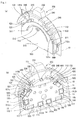
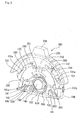
- the input device shown in Figs. 1 and 2 includes a body 100 having an accommodating part 140 formed at one end in the thickness direction; an operating member 200 having a basal end accommodated in the accommodating part 140 and a distal end projecting in a swinging operable manner to opposite sides in the width direction from an neutral position perpendicular to a bottom surface of the accommodating part 140 and in a pushing operable manner; a movement detecting means 300 for detecting the swinging and pressing movements of the operating member 200; an earth terminal 400 for dissipating static electricity charged at the operating member 200; a frame ground 500 attached to one end of the body 100 and contacted to the basal end of the operating member 200; and a returning means 600 for returning the move operated operating member 200 to the neutral position.
- the input device is attachable, in use, to a circuit board 10.
- the body 100 is a molded article made of resin, including a wall 110 of a substantially semicircular shape, in which the earth terminal 400 and first, second, third, and fourth fixed contacting point parts 310a, 310b, 310c, 310d of the movement detecting means 300 are insert molded; a bottom plate 120 arranged at a right angle to the lower end of one end face (hereinafter referred to as "inner face") in the thickness direction of the wall 110; a pair of overhanging parts 130 overhanging in the same direction as the bottom plate 120 at both sides of the top part of the inner face of the wall 110; and the accommodating part 140 formed in the inner face side of the wall 110.
- the top part is provided with a first cut-out part 111 for projecting a first projection 430 of the earth terminal 400.
- first cut-out part 111 for projecting a first projection 430 of the earth terminal 400.
- second cut-out parts 112 for projecting a pair of second projections 440 of the earth terminal 400, a pair of introducing holes 113 for leading out a pair of connecting parts 420 of the earth terminal 400, and a pair of first solder concave parts 114 for solder connecting a pair of first connecting pieces 520 of the frame ground 500.
- the introducing holes 113 and the first solder concave parts 114 are positioned close to each other so that the connecting parts 420 of the earth terminal 400 led out through the introducing holes 113 and the first connecting pieces 520 of the frame ground 500 exposed from the first solder concave parts 114 are integrally solder connectable.
- Both ends of the outer face of the wall 110 are formed with a pair of first accommodating concave parts 115 for accommodating second and third connecting ends 312b, 312c of the second and third fixed contacting point parts 310b, 310c, respectively.
- the central part of the lower end of the outer face of the wall 110 is formed with a pair of second accommodating concave parts 116 for accommodating first and fourth connecting ends 312a, 312d of the first and fourth fixed contacting point parts 310a, 310d, respectively.
- the projecting amount of the second connecting ends 312b, 312c towards the outer face side of the wall 110 and the projecting amount of the first and fourth connecting ends 312a, 312d towards the outer face side of the wall 110 are reduced by accommodating the second and third connecting ends 312b, 312c in the pair of first accommodating concave parts 115 and accommodating the first and fourth connecting ends 312a, 312d in the pair of second accommodating concave parts 116. Consequently, the thickness dimension of the device is reduced.
- a pair of second solder concave parts 117 for solder connecting a pair of second connecting pieces 530 of the frame ground 500 is formed at both ends of the lower end of the outer face of the wall 110.
- the overhanging parts 130 are formed upright at the edge of the accommodating part 140 of the wall 110. Their inner surfaces form a circular arc shape along the inner peripheral surface of the accommodating part 140. That is, the inner surfaces of the overhanging parts 130 form part of an accommodating part main body 141 of the accommodating part 140 and function as a guide surface for guiding the basal end of the operating member 200 during swinging movement.
- the outer surfaces of the overhanging parts 130 are provided with first locking parts 131 for locking the first connecting pieces 520 of the frame ground 500.
- the first locking parts 131 are rectangular recesses connecting to the first solder concave parts 114, and have first locking convex parts 131a formed at the central regions thereof.
- the overhanging parts 130 have convex parts 132 of substantially triangular prism shape formed at the upper end thereof.
- the inner surfaces of the convex part 132 are substantially perpendicular to the upper surface of the bottom plate 120. Furthermore, the lower ends of the overhanging parts 130 serve as contact stopping parts for a pair of arms 620 of the returning means 600.
- the second locking parts 121 are rectangular recesses connecting to the second solder concave parts 117, and have second locking convex parts 121a formed at the central regions thereof.
- the upper surface of the bottom plate 120 forms a bottom surface of the accommodating part main body 141 of the accommodating part 140.
- the central part of the upper surface of the bottom plate 120 is formed with a circular arc shaped concave part 122 to avoid interference with a coil part 610 of the returning means 600.
- the accommodating part 140 includes the accommodating part main body 141 that is an accommodating space defined by a concave part 141a of a substantially semicircular shape formed on the inner face of the wall 110, the inner surfaces of the overhanging parts 130, and the upper surface of the bottom plate 120; a partition wall 142, arranged at the lower end of the accommodating part main body 141, for partitioning the lower end of the accommodating part main body 141 in the thickness direction; a supporting part 143 of columnar shape formed on the inner surface of the accommodating part main body 141 (i.e., the inner face of the wall 110) that passes through the partition wall 142; and a pair of contact-stopping parts 144 arranged at both ends of the lower end of the partition wall 142.
- the accommodating part main body 141 has an opening part 141b between the convex parts 132 of the pair of overhanging parts 130.
- the opening part 141b allows the distal end of the operating member 200 to project therethrough.
- the contact-stopping part 144 is a projection of right-angled triangular shape inclined towards the outer side.
- the earth terminal 400 is a metal plate insert molded in the wall 110, and includes a contacting portion 410 of substantially circular arc shape, the pair of connecting parts 420 continuing from the ends of the contacting portion 410, the first projection 430 in a convex shape (i.e., receiving part) formed at the top of the contacting portion 410, and the pair of second projections 440 (i.e., receiving part) in a convex shape formed on opposite sides of the top of the contacting portion 410.
- the contacting portion 410 is exposed to the inner face of the wall 110 of the body 100 to contact a contacting convex portion 270 at the basal end of the operating member 200.
- the pair of connecting parts 420 are bent in the thickness direction of the wall 110 from the contacting portion 410, and exposed to the outer face of the wall 110 from the pair of introducing holes 113.
- the first and second projections 430, 440 are projected upward from the first and second cut-out parts 111, 112, and positioned near a main body part 210 of the distal end of the operating member 200.
- the movement detecting means 300 includes the first fixed contacting point part 310a commonly used for detecting the swinging and pushing movements of the operating member 200; the second and third fixed contacting point parts 310b, 310c, positioned on opposite sides of the first fixed contacting point part 310a, for detecting the swinging movement of the operating member 200 ; the fourth fixed contacting point part 310d, positioned between the first fixed contacting point part 310a and the third fixed contacting point part 310c, for detecting the pushing movement of the operating member 200; and a movable contacting point part 320 that is attached to the basal end of the operating member 200 and that slidably moves on the first, the second, the third, and the fourth fixed contacting point parts 310a, 310b, 310c, and 310d in concert with the operation movement of the operating member 200.
- the first fixed contacting point part 310a is a metal plate insert molded in the wall 110.
- the first fixed contacting point part 310a includes a first contacting point part main body 311a, having a substantially L-shape rotated to the right by 90° and being exposed from the inner face of the wall 110, and the first connecting end 312a, continuing from the lower end of the first contacting point part main body 311a and projecting from the bottom plate 120 of the body 100.
- the upper portion of the first contacting point part main body 311a is curved to a substantially circular arc shape.
- the lower portion of the first contacting point part main body 311a is a substantially straight plate-like body whose central part is bent towards the outer side (i.e., towards the second fixed contacting point part 310b side).
- the inner side of the central part is cut out in a semicircular shape.
- the first connecting end 312a is bent back to a hook shape, and has the distal end thereof accommodated in the second accommodating concave part 116 on the outer face of the wall 110 of the body 100. Thus, the distal end of the first connecting end 312a is exposed to the outer face of the wall 110 of the body 100.
- the second and third fixed contacting point parts 310b, 310c are also metal plates insert molded in the wall 110.
- the second and third fixed contacting point parts 310b, 310c respectively include second and third contacting point part main bodies 311b, 311c of substantially circular arc shape exposed from the inner face of the wall 110 and the second and third connecting ends 312b, 312c continuing from the second and third contacting point part main bodies 311b, 311c and projecting from opposite side faces in the width direction of the wall 110 of the body 100.
- the second and third contacting point part main bodies 311b, 311c and the first contacting point part main body 311a are arranged so that their upper ends form a substantially semicircular arc shape.
- the second and third connecting ends 312b, 312c are bent back to a hook shape and have the distal ends accommodated in the pair of accommodating concave parts 115 on the outer face of the wall 110 of the body 100.
- the distal ends of the second and third connecting ends 312b, 312b are thus exposed to the outer face of the wall 110 of the body 100.
- the fourth fixed contacting point part 310d is also a metal plate insert molded in the wall 110 and includes a fourth contacting point part main body 311d and the fourth connecting end 312d.
- the fourth contacting point part main body 311d is a substantially straight body, having a height dimension slightly smaller than the lower portion of the first contacting point part main body 311a, and is exposed from the inner surface of the wall 110.
- the fourth connecting end 312d continues from the lower end of the fourth contacting point part main body 311a and is projected from the bottom plate 120 of the body 100.
- the fourth fixed contacting point part 310d has the central part bent towards the outer side (i.e., towards the third fixed contacting point part 310c side) and has the inner side of the central part cut out to a semicircular shape.
- the fourth connecting end 312d is bent back to a hook shape and has the distal end accommodated in the second accommodating concave part 116 on the outer face of the wall 110 of the body 100. The distal end of the fourth connecting end 312d is thus exposed to the outer face of the wall 110 of the body 100.
- the movable contacting point part 320 includes an attachment part 321 of substantially circular arc shape to be attached to the basal end of the operating member 200, a pair of curved parts 322 (or bent parts) curved in a direction of moving away from both ends of the attachment part 321, and a pair of contacts 323 of substantially circular arc shape continuing from the pair of curved parts 322 and slidably contactable with the first, second, third, and fourth fixed contacting point parts 310a, 310b, 310c, 310d.
- a pair of temporary joining projections 321a in a convex shape is formed with spacing at the upper end of the attachment part 321.
- the pair of temporary joining projections 321a is fitted into a pair of attachment holes (not shown) formed at the upper end face of an attachment concave part 260 of the operating member 200. That is, the movable contacting point part 320 is temporarily joined to the attachment concave part 260 by fitting the pair of temporary joining projections 321a into the pair of attachment holes.
- a pair of boss grooves 321b of substantially circular shape is formed at both ends of the attachment parts 321.
- the pair of boss grooves 321b are respectively fitted with a boss 261 of the attachment concave part 260 of the operating member 200. Welding the boss 261, the attachment part 321 is secured to the attachment concave part 260 of the operating member 200.
- the curved parts 322 are curved so that the distal ends of the pair of contacts 323 project out from the attachment concave part 260 of the operating member 200 (i.e., in the direction of moving away from the attachment part 321).
- the pair of curved parts 322 elastically deform, thereby pressing the pair of contacts 323 against the first, second, third, fourth fixed contacting point part 310a, 310b, 310c, 310d.
- the operating member 200 is a molded article made of resin.
- the basal end of the operating member 200 is a two-way region of a substantially circular arc shape.
- the basal end of the operating member 200 is guided by the inner surface of the pair of overhanging parts 130 of the body 100 and supported by the pair of arms 620 of the returning means 600, thereby enabling swinging and pushing movements.
- An anastatic concave part 250 having a substantially anastatic shape in front view is formed at one end face in the thickness direction of the basal end of the operating member 200.
- a contacting part 251 is formed at the upper end of the anastatic concave part 250.
- the contacting part 251 is a hill shaped convex part that rides over a raised part or detent 513 of the frame ground 500 in response to the pushing operation.
- the attachment concave part 260 of substantially circular arc shape to be attached with the movable contacting point part 320 of the movement detecting means 300 is arranged on the other end face in the thickness direction of the basal end of the operating member.
- the pair of attachment holes (not shown) to which the temporary joining projections 321a of the movable contacting point part 320 are fitted is formed at the upper end face of the attachment concave part 260.
- the welding bosses 261 to be fitted into the pair of boss grooves 321b of the movable contacting point part 320 are formed on the attachment concave part 260.
- both edge parts 262 on the lower side of the attachment concave part 260 are inclined towards the pair of curved parts 322 of the movable contacting point part 320 attached to the attachment concave part 260.
- the edge parts 262 on the lower side of the attachment concave part 260 thus do not interfere with the elastically deformed pair of contacts 323.
- the contacting convex portion 270 having a substantially circular arc shape is formed on the upper edge of the attachment concave part 260.
- the contacting convex portion 270 is guided by the upper edge of a substantially semicircular shaped concave part of the accommodating part main body 141 of the body 100 and is slidably contacted to the contacting portion 410 of the earth terminal 400.
- a pair of locking projections 280 is formed at one end in the thickness direction of the two distal end faces of the basal end of the operating member 200. As shown in Fig. 2, the pair of locking projections 280 locks the pair of arms 620 of the returning means 600 between the edges of the concave part 141a of the accommodating part main body 141 of the wall 110.
- the other end in the thickness direction of the two distal end faces of the basal end of the operating member 200 is a region to which the pair of arms 620 of the returning means 600 contact, and faces the pair of contact-stopping parts 144 of the accommodating part 140 in a contacting manner by way of the pair of arms 620 of the returning means 600.
- the distal end of the operating member 200 includes a main body part 210 of a substantially trapezoidal shape arranged continuing from the basal end of the operating member 200, an arm part 220 of substantially semicircular arc shape arranged at the upper end of the main body part 210, an operation convex part 230 arranged at the top of the arm part 220, and a pair of projections 240 of circular arc shape arranged at both ends of the main body part 210.
- the thickness dimension of the main body part 210 and the pair of projections 240 is a dimension enabling fitting into the opening part 141b of the accommodating part main body 141 of the body 100 in the pushing operation.
- the width dimension of the main body part 210 and the pair of projections 240 is a dimension slightly smaller than the width dimension of the opening part 141b (i.e., distance between the pair of convex parts 132).
- the returning means 600 includes the coil part 610, and the pair of arms 620 continuing from both ends of the coil part 610.
- the coil part 610 has an inner diameter larger than the outer diameter of the supporting part 143 of the body 100, so that the supporting part can be inserted therein. The coil part 610 is thus supported by the supporting part 143.
- the pair of arms 620 extends substantially horizontally, and contacts the other ends in the thickness direction of the two distal end faces of the basal end of the operating member 200 and the lower end of the overhanging part 130 of the body 100.
- the arms 620 thus urge the two distal end faces of the basal end of the operating member 200 substantially equally towards the inner surface of the overhanging parts 130 (i.e., upward), thereby holding the operating member 200 at the neutral position perpendicular to the bottom surface of the accommodating part 140.
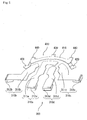
- the frame ground 500 is a plate shaped body made of metal that includes a frame main body 510 of substantially semicircular shape, a pair of first connecting pieces 520 arranged at a right angle at the edge on both sides of the top of the frame main body 510, a pair of second connecting pieces 530 arranged at a right angle at both ends in the width direction of the lower end of the frame main body 510, and a pair of side plate parts 540 arranged at both ends in the width direction of the lower end of the frame main body 510.
- the first and second connecting pieces 520, 530 are locking strips of substantially rectangular shape to be locked to the first and second locking parts 131, 121 of the body 100.
- First and second locking holes 521, 531 to be locked to the first and second locking convex parts 131a, 121a of the first and second locking parts 131, 121 are formed at the central part of the basal end of the first and second connecting pieces 520, 530.
- the length dimension of the first and second connecting pieces 520, 530 is a length dimension at which the distal ends are exposed from the first and second solder concave parts 114, 117, respectively, of the body 100 while being locked to the first and second locking parts 131, 121 of the body 100.
- the frame main body 510 contacts the basal end of the operating member 200 accommodated in the accommodating part 140 of the body 100 with the first and second connecting pieces 520, 530 locked to the first and second locking parts 131, 121 of the body 100.
- a slit 511 of semicircular arc shape, a movable piece part 512 defined by the slit 511, and the raised part 513 in a convex shape formed at the top of the central part of the movable piece part 512 are arranged at the central part of the upper end of the frame main body 510.
- the raised part 513 contacts the contacting part 251 through the pushing movement of the operating member 200.
- the movable piece part 512 thereby elastically deforms to the outer side.
- the circuit board 10 is attached to the outer face of the wall 110 of the body 100. Pairs of first and second earth patterns 11, 12 and pairs of first and second electrode patterns 13, 14 are formed on the surface of the circuit board 10 facing the body, as shown in Fig. 1(b).
- the first earth patterns 11 are arranged on the circuit board 10 so as to correspond to the positions of the pair of connecting parts 420 of the earth terminals 400 and the distal ends of the pair of first connecting pieces 520 of the frame ground 500, and are integrally solder connected with the pair of connecting parts 420 of the earth terminal 400 and the distal ends of the pair of first connecting pieces 520 of the frame ground 500.
- the second earth patterns 12 are arranged on the circuit board 10 so as to correspond to the positions of the distal ends of the pair of second connecting pieces 530 of the frame ground 500, and are solder connected to the distal ends of the pair of second connecting pieces 530 of the frame ground 500.
- static electricity charged at the operating member 200 jumps to the first and second projections 430, 440 of the earth terminal 400, and flows to the first earth patterns 11 of the circuit board 10 through the contacting portion 410 and the connecting parts 420.
- the static electricity flows to the first earth patterns 11 of the circuit board 10 through the contacting portion 410 and the connecting parts 420 of the earth terminal 400.
- the static electricity may also flow to the first earth patterns 11 of the circuit board 10 through the frame main body 510 and the first connecting pieces 520 of the frame ground 500.
- the static electricity alternatively flows to the second earth patterns 12 of the circuit board 10 through the frame main body 510 and the second connecting pieces 530 of the frame ground 500.
- the first electrode patterns 13 are arranged on the circuit board 10 so as to correspond to the positions of the second and third connecting ends 312b, 312c of the second and third fixed contacting point parts 310b, 310c, and are solder connected to the second and third connecting ends 312b, 312c of the second and third fixed contacting point parts 310b, 310c.
- the second electrode patterns 14 are arranged on the circuit board 10 so as to correspond to the positions of the first and fourth connecting ends 312a, 312d of the first and fourth fixed contacting point parts 310a, 310d, and are solder connected to the first and fourth connecting ends 312a, 312d of the first and fourth fixed contacting point parts 310a, 310d.
- the pair of temporary joining projections 321a of the attachment part 321 of the movable contacting point part 320 are inserted while being positioned at the pair of attachment holes of the attachment concave part 260 of the operating member 200.
- the movable contacting point part 320 is thereby temporary joined to the attachment concave part 260.
- the bosses 261 of the attachment concave part 260 of the operating member are then fitted into the pair of boss grooves 321b of the attachment part 321 of the movable contacting point part 320. Welding the boss 261, the attachment part 321 of the movable contacting point part 320 is secured to the attachment concave part 260 of the operating member 200.
- the supporting part 143 of the body 100 is inserted into the coil part 610 of the returning means 600, and at the same time, the arms 620 are contacted to the lower ends of the pair of overhanging parts 130 of the body 100.
- the body 100 is now ready to receive the basal end of the operating member 200 in the accommodating part main body 141 of the accommodating part 140. More particularly, the basal end is accommodated in the accommodating part main body 141 while pushing the two distal end faces of the basal end of the operating member 200 against the pair of arms 620 of the returning means 600. When such pressing of the operating member 200 is released, the basal end of the operating member 200 is biased towards the inner surfaces of the overhanging parts 130 of the body 100 by the biasing force of the returning means 600, and held at the neutral position.
- the first and second connecting pieces 520, 530 of the frame ground 500 are locked to the first and second locking parts 131, 121 of the body 100 to attach the frame ground 500 to the body 100.
- the frame ground 500 thus covers the accommodating part 140 of the body 100.
- the pair of first earth patterns 11 of the circuit board 10 is positioned and brought into contact with the pair of connecting parts 420 of the earth terminals 400 and the distal ends of the pair of first connecting pieces 520 of the frame ground 500;
- the pair of second earth patterns 12 is positioned and brought into contact with the distal ends of the pair of second connecting pieces 530 of the frame ground 500;
- the pair of first electrode patterns 13 is positioned and brought into contact with the second and third connecting ends 312b, 312c of the second and third fixed contacting point parts 310b, 310c;
- the pair of second electrode patterns 14 is positioned and brought into contact with the first and fourth connecting ends 312a, 312d of the first and fourth fixed contacting point parts 310a, 310d.
- solder connections may be performed all at once using solder reflow.
- one of the contacts 323 of the movable contacting point part 320 slidably contacts the upper end of the first contacting point part main body 311a of the first fixed contacting point part 310a, and the other contact 323 slidably contacts the third contacting point part main body 311c of the third fixed contacting point part 310c.
- the first fixed contacting point part 310a and the third fixed contacting point part 310c thereby become electrically continuous, and a signal is output to an electronic equipment (not shown).
- one contact 323 of the movable contacting point part 320 slidably contacts the second contacting point part main body 310b of the second fixed contacting point part 311b, and the other contact 323 slidably contacts the upper end of the first contacting point part main body 311a of the first fixed contacting point part 310a.
- the first fixed contacting point part 310a and the second fixed contacting point part 310b thereby become electrically continuous, and a signal is output to an electronic equipment (not shown).
- one of the pair of projections 240 of the operating member 200 is positioned above one of the pair of convex parts 132 so as to be contactable therewith.
- the pushing operation of the operating member 200 in time of the swinging operation is prevented by positioning one projection 240 at the position above one convex part 132 so as to be contactable therewith.
- the arm 620 on the operating direction side is pressed against the distal end face on the moving direction side of the basal end of the operating member 200, and the arm 620 on the non-operating direction side is maintained in a state contacting the lower end of the corresponding overhanging part 130 of the body 100, so that the coil part 610 is compressed.
- the distal end face on the moving direction side of the basal end of the operating member 200 contacts the contact-stopping part 144 on the operating direction side of the accommodating part 140 by way of the arm 620 on the operating direction side.
- the pushing operation of the operating member 200 in time of the swinging operation is thereby also prevented.
- the arm 620 on the operating direction side presses the distal end face on the moving direction side of the basal end of the operating member 200 to return the operating member to the neutral position.
- one of the contacts 323 of the movable contacting point part 320 slidably contacts the lower end of the first contacting point part main body 311a of the first fixed contacting point part 310a, and the other contact 323 slidably contacts the fourth contacting point part main body 311d of the fourth fixed contacting point part 310d.
- the first fixed contacting point part 310a and the fourth fixed contacting point part 310d thereby become electrically continuous, and a signal is output to an electronic equipment (not shown).
- Both outer side faces in the width direction of the pair of projections 240 of the operating member 200 are guided by the inner surfaces of the pair of concave parts 132 of the body 100, whereby the swinging operation of the operating member 200 in time of the pushing operation is prevented.
- the pair of arms 620 is pressed against the two distal end faces of the basal end of the operating member 200, so that the coil part 610 is compressed.
- the two distal end faces of the basal end of the operating member 200 contact the pair of contact-stopping parts 144 of the accommodating part 140. The swinging operation of the operating member 200 in time of the pushing operation is thereby also prevented.
- the contacting part 251 of the operating member 200 contacts the raised part 513 of the frame ground 500 and rides over the raised part 513.
- the movable piece part 512 then elastically deforms. The operation feeling is thereby generated in the pushing operation of the operating member 200.
- the pair of arms 620 presses the two distal end faces of the basal end of the operating member 200 upward to return the operating member to the neutral position.
- the earth terminal 400 and the first, second, third, and fourth fixed contacting point parts 310a, 310b, 310c, and 310d are insert molded to the body 100, in a state that the connecting parts 420 of the earth terminal 400 and the first, second, third, and fourth connecting ends 312a, 312b, 312c, and 312d of the first, second, third, and fourth fixed contacting point parts 310a, 310b, 310c, and 310d are exposed from the outer surface of the wall 110 of the body 100.
- the earth terminal 400 and the first, second, third, and fourth fixed contacting point parts 310a, 310b, 310c, and 310d can be easily assembled to the body 100 without performing a separate preceding or following process as in the prior art. Furthermore, in addition to the connecting parts 420 of the earth terminal 400 and the first, second, third, and fourth connecting ends 312a, 312b, 312c, and 312d of the first, second, third, and fourth fixed contacting point parts 310a, 310b, 310c, and 310d exposed from the outer surface of the wall 110 of the body 100, the distal ends of the first and second connecting pieces 520, 530 of the frame ground 500 are also exposed from the outer surface of the wall 110 so that all of the said elements can be solder connected to the circuit board 10 at one time.
- the earth terminal 400, and the first, second, third, and fourth fixed contacting point parts 310a, 310b, 310c, and 310d and the frame ground 500 are easily electrically connected to the circuit board 10 without performing a separate preceding or following process as in the prior art.
- the assembly of the components to the body 100 and electrical connection task of each component to the circuit board 10 can thus be very easily performed, whereby the manufacturing steps can be reduced and the cost can also be reduced.
- the body 100 may be of any type as long as the accommodating part is arranged at one end and the circuit board can be attached to the other end.
- the earth terminal 400 is a terminal integrally arranged with the body and includes a receiving part exposed from the body and positioned near the operating member and a connecting part exposed from the other end face of the body and solder connectable to the earth pattern of the circuit board.
- the frame ground 500 is a countermeasure against electrostatic discharge through the operating member 200, but the frame ground may be omitted. In this case, it is possible to provide a frame that simply covers the accommodating part of the body.
- the first and second connecting pieces 520, 530 of the frame ground 500 serve as locking pieces, they are not limited to such configuration. That is, separately from the locking pieces, there may be provided connecting pieces merely for connecting with the earth patterns 11.
- the shapes of the first, second, third, and fourth fixed contacting point parts 310a, 310b, 310c, and 310d and the movable contacting point part 320 may be of any shape as long as the movable contacting point part slidably contacts the fixed contacting point parts in accordance with the movement of the operating member. Moreover, design change may be made to have the fixed contacting point parts as resistor patterns to constitute variable resistors.
- the above described arrangement of the connecting parts 420 of the earth terminal 400; the first and second connecting pieces 520, 530 of the frame ground 500; and the first, second, third, and fourth connecting ends 312a, 312b, 312c, and 312d of the first, second, third, the fourth fixed contacting point parts 310a, 310b, 310c, and 310d of the movement detecting means 300 is merely one example and is not limited thereto.
- the arrangement of the earth patterns 11, 12 and the electrode patterns 13, 14 of the circuit board 10 may be optionally changed in design according to the arrangement of the connecting parts 420 of the earth terminal 400; the first and second connecting pieces 520, 530 of the frame ground 500; and the first, second, third, and fourth connecting ends 312a, 312b, 312c, and 312d of the first, second, third, and fourth fixed contacting point parts 310a, 310b, 310c, and 310d of the movement detecting means 300.
- the operating member 200 may be of any type as long as its basal end is accommodated in the accommodating part of the body and its distal end is projected from the accommodating part so as to be operable. Although it is described above that the operating member 200 can be operated in two directions (i.e., swinging and pushing operable), but the operating member may be adapted only for one type of operation or may be swinging operable in multi directions.
- the neutral position of the operating member can be set at any point.
- the returning means 600 may be of any type as long as it can return the operating member to the neutral position.
Landscapes
- Switches With Compound Operations (AREA)
- Switch Cases, Indication, And Locking (AREA)
- Telephone Set Structure (AREA)
- Coupling Device And Connection With Printed Circuit (AREA)
Abstract
Description
- The present invention relates to input devices included in small electronic equipment, such as mobile terminal devices, for inputting operation to the electronic equipment.
- In some input devices of this kind, for example as disclosed in
Japanese Utility Model Registered No. 3048274 Japanese Laid-Open Patent Publication No. 2005-149925 - Such an input device has a drawback in that static electricity charged when a user touches the operating member may flow through the operating member to an internal circuit such as the switching means. To overcome such a drawback,
Japanese Laid-Open Patent Publication No. 09-63416 - In such an input device, a signal terminal and an earth terminal are arranged on one metal plate, which is insert molded in a case, and later a coupling part of the signal terminal and the earth terminal is split. That is, it is required to provide a separate process of separating the signal terminal and the earth terminal after integrally arranging the signal terminal and the earth terminal in the case. Such separate process leads to increased manufacturing steps.
- Furthermore, since the earth terminal must be folded at a right angle before being solder connected to the circuit board, another separate process is required before solder connection, which also leads to increased manufacturing steps.
- The present invention is proposed in view of the above situation, and aims to provide an input device in which assembly and electrical connection of the earth terminal can be easily performed.
- In order to overcome such problems, the present invention provides an input device mountable on a circuit board, the circuit board including an electrode pattern and an earth pattern, the input device comprising a body having an accommodating part formed at one end; an operating member having a basal end accommodated in the accommodating part and a distal end projected from the accommodating part in an operable manner; a fixed contacting point part integrally arranged with the body and exposed to the accommodating part so as to be electrically connectable to the electrode pattern; a movable contacting point part arranged at the basal end of the operating member and slidably movable on the fixed contacting point part in concert with operation movement of the operating member; and an earth terminal for discharging static electricity charged in the operating member, being electrically connectable to the earth pattern, wherein the earth terminal is integrally arranged with the body and includes a receiving part exposed from the body and positioned near the operating member and a connecting part exposed from the other end face of the body and solder connectable to the earth pattern of the circuit board.
- In the claimed input device, the earth terminal is integrally arranged with the body; particularly, the receiving part of the earth terminal is exposed from the body and arranged near the operating member, while the connecting part of the earth terminal is exposed from the other end face of the body. Consequently, the earth terminal and the fixed contacting point part can be easily assembled to the body without performing a separate preceding or following process as in the prior art. Furthermore, the connecting part of the earth terminal is exposed from the other end face of the body and solder connectable to the earth pattern of the circuit board. Such earth terminal can be easily electrically connected to the circuit board without performing a separate preceding or following process as in the
- The input device may further include a frame ground attached to the one end of the body so as to cover the accommodating part and contactable with the basal end of the operating member. In this case, the frame ground includes a connecting piece exposed from the other end face of the body and solder connectable to the earth pattern of the circuit board.
- The static electricity charged in the operating member is thus more suitably discharged by using the frame ground in addition to the earth terminal. Furthermore, as the connecting piece of the frame ground is exposed from the other end face of the body and solder connected to the earth pattern of the circuit board, the frame ground can be easily electrically connected to the earth pattern of the circuit board without performing a separate process. Moreover, the connecting piece of the frame ground is exposed from the same surface of the body as the connecting part of the earth terminal so as to be solder connected to the earth pattern. As a result, solder connection can be carried out all at once using solder reflow etc. and thus the input device of the invention is suited for mass production.
- The connecting piece of the frame ground and the connecting part of the earth terminal are preferably exposed from the other end face of the body so as to be positioned close to each other and are solder connectable integrally to the earth pattern of the circuit board. In this case, the connecting piece of the frame ground and the connecting part of the earth terminal are solder connected all at once to the earth pattern of the circuit board.
- It is preferable that the connecting piece of the frame ground functions as a locking piece, and in a state of being locked to a locking part formed on the body, a distal end of the connecting piece is exposed from the other end face of the body. The connecting piece also functioning as a locking piece, the device can be manufactured with a reduced number of components and can be miniaturized.
- The fixed contacting point part preferably includes a connecting end exposed from the other end face of the body and solder connectable to the electrode pattern of the circuit board.
- Thus, the fixed contacting point part is easily electrically connected to the electrode pattern of the circuit board by exposing the connecting end of the fixed contacting point part from the other end face of the body and solder connecting the same to the electrode pattern of the circuit board. Furthermore, since the connecting end of the fixed contacting point part is exposed from the same surface of the body as the connecting piece of the frame ground and the connecting part of the earth terminal so as to be solder connected to the earth pattern, solder connection can be carried out all at once using solder reflow etc. Therefore, the input device of the invention is suited for mass production.
- An accommodating concave part for accommodating the connecting end of the fixed contacting point part is preferably formed in the other end face of the body. In this case, the connecting end of the fixed contacting point part is prevented from projecting out from the other end face side of the body as the connecting end is accommodated in the accommodating concave part. Thus, the thickness dimension of the device can be reduced.
- The operating member may be swing operable to either side from a neutral position substantially perpendicular to a bottom surface of the accommodating part and may also be push operable from the neutral position. In this configuration, the accommodating part of the body may include an opening part for projecting the distal end of the operating member in an operable manner; a pair of projections may be formed at opposite ends in a swinging direction of the distal end of the operating member; and the pair of projections may be guided by both edges in the swinging direction of the opening part when the operating member is pushed down, and one of the projections may be contactable with one of the edges in the swinging direction of the opening part when the operating member is swung.
- That is, in a press-down operation, the pair of projections of the operating member is guided by both edges of the opening part of the body. Even if the operating member is carelessly swing operated during the press-down operation, one of the projections on the swinging operation direction side contacts one of the edges of the opening part of the body, thereby preventing the swinging operation. On the other hand, in a swinging operation, one of the projections on the swinging operation direction side of the operating member is positioned above and contactable to the edge on the swinging operation direction side of the opening part of the body. Thus, even if the operating member is carelessly pressed down during the swinging operation, the lower end of the one projection contacts the one edge, thereby preventing the press-down operation.
- The frame ground may include a movable piece part defined by a slit, and a raised part formed at a central part of the movable piece part. The basal end of the operating member may be provided with a contacting part in a convex shape for riding over the raised part upon pushing movement of the operating member.
- In other words, when the operating member is pressed down, the contacting part of the operating member contacts and rides over the raised part of the frame ground. The movable piece part of the frame ground thereby elastically deforms. An operation feeling is thereby generated in the pushing operation of the operating member.
- According to the input device of the present invention, the earth terminal can be easily assembled to the body and electrically connected to the circuit board without performing a separate preceding or following process as in the prior art. Consequently, the invention can reduce the number of manufacturing steps and the cost.
- An input device according to the embodiment of the present invention will now be described by way of example only with reference to the drawings, in which:
- Fig. 1 is a schematic perspective view of an input device according to an embodiment of the present invention where (a) is a view showing the device from one end side in the thickness direction and (b) is a view showing the device from the other end side in the thickness direction;
- Fig. 2 is a schematic perspective view showing a state in which a frame ground of the device is detached;
- Fig. 3 is a view showing a body insert molded with fixed contacting point parts of the device, where (a) is a schematic front view of the body and (b) is a schematic rear view of the body;
- Fig. 4 is a view showing a body insert molded with the fixed contacting point parts of the device, where (a) is a schematic plan view of the body, (b) is a schematic bottom view of the body, (c) is a schematic side view of the body;
- Fig. 5 is a schematic perspective view showing an arrangement of an earth terminal of the device and the fixed contacting point parts of a detecting means;
- Fig. 6 is a schematic perspective view of an operating member of the device, where (a) is a view seen from one end side in the thickness direction and (b) is a view showing a state in which a movable contacting point part of the detecting means is attached from the other end side in the thickness direction;
- Fig. 7 is a view showing the movable contacting point part of the detecting means of the device, where (a) is a schematic front view of the movable contacting point part and (b) is a schematic rear view of the movable contacting point part; and
- Fig. 8 is a schematic perspective view of the frame ground of the device, where (a) is a view seen from one end side in the thickness direction and (b) is a view seen from the other end side in the thickness direction.
- In the description which follows, relative spatial terms such as "down", "left", "right", "bottom", "upright", "upward", etc., are used for the convenience of the skilled reader and refer to the orientation of the input device and its constituent parts as depicted in the drawings. No limitation is intended by use of these terms, either in use of the invention, during its manufacture, custody, or sale, or during assembly of its constituent parts.
- The input device shown in Figs. 1 and 2 includes a
body 100 having anaccommodating part 140 formed at one end in the thickness direction; anoperating member 200 having a basal end accommodated in theaccommodating part 140 and a distal end projecting in a swinging operable manner to opposite sides in the width direction from an neutral position perpendicular to a bottom surface of theaccommodating part 140 and in a pushing operable manner; a movement detecting means 300 for detecting the swinging and pressing movements of theoperating member 200; anearth terminal 400 for dissipating static electricity charged at theoperating member 200; aframe ground 500 attached to one end of thebody 100 and contacted to the basal end of theoperating member 200; and a returningmeans 600 for returning the move operatedoperating member 200 to the neutral position. The input device is attachable, in use, to acircuit board 10. - As shown in Figs. 2, 3, 4 and 5 the
body 100 is a molded article made of resin, including awall 110 of a substantially semicircular shape, in which theearth terminal 400 and first, second, third, and fourth fixedcontacting point parts bottom plate 120 arranged at a right angle to the lower end of one end face (hereinafter referred to as "inner face") in the thickness direction of thewall 110; a pair ofoverhanging parts 130 overhanging in the same direction as thebottom plate 120 at both sides of the top part of the inner face of thewall 110; and theaccommodating part 140 formed in the inner face side of thewall 110. - Looking at the other end face (hereinafter referred to as "outer face") in the thickness direction of the
wall 110, the top part is provided with a first cut-outpart 111 for projecting afirst projection 430 of theearth terminal 400. On opposite sides of the top part on the outer face (i.e., the other end face in the thickness direction of the body 100) of thewall 110, there are formed a pair of second cut-outparts 112 for projecting a pair ofsecond projections 440 of theearth terminal 400, a pair of introducingholes 113 for leading out a pair of connectingparts 420 of theearth terminal 400, and a pair of first solderconcave parts 114 for solder connecting a pair of first connectingpieces 520 of theframe ground 500. - The introducing
holes 113 and the first solderconcave parts 114 are positioned close to each other so that the connectingparts 420 of theearth terminal 400 led out through the introducingholes 113 and the first connectingpieces 520 of theframe ground 500 exposed from the first solderconcave parts 114 are integrally solder connectable. - Both ends of the outer face of the
wall 110 are formed with a pair of first accommodatingconcave parts 115 for accommodating second and third connectingends contacting point parts wall 110 is formed with a pair of second accommodatingconcave parts 116 for accommodating first and fourth connectingends contacting point parts - In the above arrangement, the projecting amount of the second connecting
ends wall 110 and the projecting amount of the first and fourth connectingends wall 110 are reduced by accommodating the second and third connectingends concave parts 115 and accommodating the first and fourth connectingends concave parts 116. Consequently, the thickness dimension of the device is reduced. - Furthermore, a pair of second solder
concave parts 117 for solder connecting a pair of second connectingpieces 530 of theframe ground 500 is formed at both ends of the lower end of the outer face of thewall 110. - The overhanging
parts 130 are formed upright at the edge of theaccommodating part 140 of thewall 110. Their inner surfaces form a circular arc shape along the inner peripheral surface of theaccommodating part 140. That is, the inner surfaces of the overhangingparts 130 form part of an accommodating partmain body 141 of theaccommodating part 140 and function as a guide surface for guiding the basal end of the operatingmember 200 during swinging movement. - The outer surfaces of the overhanging
parts 130 are provided with first lockingparts 131 for locking the first connectingpieces 520 of theframe ground 500. Thefirst locking parts 131 are rectangular recesses connecting to the first solderconcave parts 114, and have first lockingconvex parts 131a formed at the central regions thereof. - The overhanging
parts 130 haveconvex parts 132 of substantially triangular prism shape formed at the upper end thereof. The inner surfaces of theconvex part 132 are substantially perpendicular to the upper surface of thebottom plate 120. Furthermore, the lower ends of the overhangingparts 130 serve as contact stopping parts for a pair ofarms 620 of the returningmeans 600. - At opposite ends of the lower surface of the
bottom plate 120, there are formed a pair ofsecond locking parts 121 for locking the pair of second connectingpieces 530 of theframe ground 500. Thesecond locking parts 121 are rectangular recesses connecting to the second solderconcave parts 117, and have second lockingconvex parts 121a formed at the central regions thereof. - The upper surface of the
bottom plate 120 forms a bottom surface of the accommodating partmain body 141 of theaccommodating part 140. The central part of the upper surface of thebottom plate 120 is formed with a circular arc shapedconcave part 122 to avoid interference with acoil part 610 of the returningmeans 600. - As shown in Figs. 2 and 3, the
accommodating part 140 includes the accommodating partmain body 141 that is an accommodating space defined by aconcave part 141a of a substantially semicircular shape formed on the inner face of thewall 110, the inner surfaces of the overhangingparts 130, and the upper surface of thebottom plate 120; apartition wall 142, arranged at the lower end of the accommodating partmain body 141, for partitioning the lower end of the accommodating partmain body 141 in the thickness direction; a supportingpart 143 of columnar shape formed on the inner surface of the accommodating part main body 141 (i.e., the inner face of the wall 110) that passes through thepartition wall 142; and a pair of contact-stoppingparts 144 arranged at both ends of the lower end of thepartition wall 142. - The accommodating part
main body 141 has anopening part 141b between theconvex parts 132 of the pair of overhangingparts 130. Theopening part 141b allows the distal end of the operatingmember 200 to project therethrough. - The contact-stopping
part 144 is a projection of right-angled triangular shape inclined towards the outer side. - As shown in Fig. 5, the
earth terminal 400 is a metal plate insert molded in thewall 110, and includes a contactingportion 410 of substantially circular arc shape, the pair of connectingparts 420 continuing from the ends of the contactingportion 410, thefirst projection 430 in a convex shape (i.e., receiving part) formed at the top of the contactingportion 410, and the pair of second projections 440 (i.e., receiving part) in a convex shape formed on opposite sides of the top of the contactingportion 410. - The contacting
portion 410 is exposed to the inner face of thewall 110 of thebody 100 to contact a contactingconvex portion 270 at the basal end of the operatingmember 200. The pair of connectingparts 420 are bent in the thickness direction of thewall 110 from the contactingportion 410, and exposed to the outer face of thewall 110 from the pair of introducingholes 113. - The first and
second projections parts main body part 210 of the distal end of the operatingmember 200. - As shown in Figs. 5, 6, and 7, the movement detecting means 300 includes the first fixed contacting
point part 310a commonly used for detecting the swinging and pushing movements of the operatingmember 200; the second and third fixed contactingpoint parts point part 310a, for detecting the swinging movement of the operatingmember 200 ; the fourth fixed contactingpoint part 310d, positioned between the first fixed contactingpoint part 310a and the third fixed contactingpoint part 310c, for detecting the pushing movement of the operatingmember 200; and a movable contactingpoint part 320 that is attached to the basal end of the operatingmember 200 and that slidably moves on the first, the second, the third, and the fourth fixed contactingpoint parts member 200. - As shown in Figs. 3 and 5, the first fixed contacting
point part 310a is a metal plate insert molded in thewall 110. The first fixed contactingpoint part 310a includes a first contacting point partmain body 311a, having a substantially L-shape rotated to the right by 90° and being exposed from the inner face of thewall 110, and the first connectingend 312a, continuing from the lower end of the first contacting point partmain body 311a and projecting from thebottom plate 120 of thebody 100. - The upper portion of the first contacting point part
main body 311a is curved to a substantially circular arc shape. The lower portion of the first contacting point partmain body 311a is a substantially straight plate-like body whose central part is bent towards the outer side (i.e., towards the second fixed contactingpoint part 310b side). The inner side of the central part is cut out in a semicircular shape. - The first connecting
end 312a is bent back to a hook shape, and has the distal end thereof accommodated in the second accommodatingconcave part 116 on the outer face of thewall 110 of thebody 100. Thus, the distal end of the first connectingend 312a is exposed to the outer face of thewall 110 of thebody 100. - As shown in Figs. 3 and 5, the second and third fixed contacting
point parts wall 110. The second and third fixed contactingpoint parts main bodies wall 110 and the second and third connecting ends 312b, 312c continuing from the second and third contacting point partmain bodies wall 110 of thebody 100. - The second and third contacting point part
main bodies main body 311a are arranged so that their upper ends form a substantially semicircular arc shape. The second and third connecting ends 312b, 312c are bent back to a hook shape and have the distal ends accommodated in the pair of accommodatingconcave parts 115 on the outer face of thewall 110 of thebody 100. The distal ends of the second and third connecting ends 312b, 312b are thus exposed to the outer face of thewall 110 of thebody 100. - As shown in Figs. 3 and 5, the fourth fixed contacting
point part 310d is also a metal plate insert molded in thewall 110 and includes a fourth contacting point partmain body 311d and the fourth connectingend 312d. The fourth contacting point partmain body 311d is a substantially straight body, having a height dimension slightly smaller than the lower portion of the first contacting point partmain body 311a, and is exposed from the inner surface of thewall 110. The fourth connectingend 312d continues from the lower end of the fourth contacting point partmain body 311a and is projected from thebottom plate 120 of thebody 100. - The fourth fixed contacting
point part 310d has the central part bent towards the outer side (i.e., towards the third fixed contactingpoint part 310c side) and has the inner side of the central part cut out to a semicircular shape. - The fourth connecting
end 312d is bent back to a hook shape and has the distal end accommodated in the second accommodatingconcave part 116 on the outer face of thewall 110 of thebody 100. The distal end of the fourth connectingend 312d is thus exposed to the outer face of thewall 110 of thebody 100. - As shown in Figs. 6 and 7, the movable contacting
point part 320 includes anattachment part 321 of substantially circular arc shape to be attached to the basal end of the operatingmember 200, a pair of curved parts 322 (or bent parts) curved in a direction of moving away from both ends of theattachment part 321, and a pair ofcontacts 323 of substantially circular arc shape continuing from the pair ofcurved parts 322 and slidably contactable with the first, second, third, and fourth fixed contactingpoint parts - A pair of temporary joining
projections 321a in a convex shape is formed with spacing at the upper end of theattachment part 321. The pair of temporary joiningprojections 321a is fitted into a pair of attachment holes (not shown) formed at the upper end face of an attachmentconcave part 260 of the operatingmember 200. That is, the movable contactingpoint part 320 is temporarily joined to the attachmentconcave part 260 by fitting the pair of temporary joiningprojections 321a into the pair of attachment holes. - A pair of
boss grooves 321b of substantially circular shape is formed at both ends of theattachment parts 321. The pair ofboss grooves 321b are respectively fitted with aboss 261 of the attachmentconcave part 260 of the operatingmember 200. Welding theboss 261, theattachment part 321 is secured to the attachmentconcave part 260 of the operatingmember 200. - The
curved parts 322 are curved so that the distal ends of the pair ofcontacts 323 project out from the attachmentconcave part 260 of the operating member 200 (i.e., in the direction of moving away from the attachment part 321). Thus, when the pair ofcontacts 323 contact the first, second, third, fourth fixed contactingpoint part curved parts 322 elastically deform, thereby pressing the pair ofcontacts 323 against the first, second, third, fourth fixed contactingpoint part - As shown in Figs. 2 and 6, the operating
member 200 is a molded article made of resin. The basal end of the operatingmember 200 is a two-way region of a substantially circular arc shape. The basal end of the operatingmember 200 is guided by the inner surface of the pair of overhangingparts 130 of thebody 100 and supported by the pair ofarms 620 of the returning means 600, thereby enabling swinging and pushing movements. - An anastatic
concave part 250 having a substantially anastatic shape in front view is formed at one end face in the thickness direction of the basal end of the operatingmember 200. A contactingpart 251 is formed at the upper end of the anastaticconcave part 250. The contactingpart 251 is a hill shaped convex part that rides over a raised part ordetent 513 of theframe ground 500 in response to the pushing operation. - The attachment
concave part 260 of substantially circular arc shape to be attached with the movable contactingpoint part 320 of the movement detecting means 300 is arranged on the other end face in the thickness direction of the basal end of the operating member. The pair of attachment holes (not shown) to which the temporary joiningprojections 321a of the movable contactingpoint part 320 are fitted is formed at the upper end face of the attachmentconcave part 260. Thewelding bosses 261 to be fitted into the pair ofboss grooves 321b of the movable contactingpoint part 320 are formed on the attachmentconcave part 260. Furthermore, bothedge parts 262 on the lower side of the attachmentconcave part 260 are inclined towards the pair ofcurved parts 322 of the movable contactingpoint part 320 attached to the attachmentconcave part 260. Theedge parts 262 on the lower side of the attachmentconcave part 260 thus do not interfere with the elastically deformed pair ofcontacts 323. - Furthermore, the contacting
convex portion 270 having a substantially circular arc shape is formed on the upper edge of the attachmentconcave part 260. The contactingconvex portion 270 is guided by the upper edge of a substantially semicircular shaped concave part of the accommodating partmain body 141 of thebody 100 and is slidably contacted to the contactingportion 410 of theearth terminal 400. - A pair of locking
projections 280 is formed at one end in the thickness direction of the two distal end faces of the basal end of the operatingmember 200. As shown in Fig. 2, the pair of lockingprojections 280 locks the pair ofarms 620 of the returning means 600 between the edges of theconcave part 141a of the accommodating partmain body 141 of thewall 110. The other end in the thickness direction of the two distal end faces of the basal end of the operatingmember 200 is a region to which the pair ofarms 620 of the returning means 600 contact, and faces the pair of contact-stoppingparts 144 of theaccommodating part 140 in a contacting manner by way of the pair ofarms 620 of the returningmeans 600. - As shown in Figs. 2 and 6, the distal end of the operating
member 200 includes amain body part 210 of a substantially trapezoidal shape arranged continuing from the basal end of the operatingmember 200, anarm part 220 of substantially semicircular arc shape arranged at the upper end of themain body part 210, an operationconvex part 230 arranged at the top of thearm part 220, and a pair ofprojections 240 of circular arc shape arranged at both ends of themain body part 210. - The thickness dimension of the
main body part 210 and the pair ofprojections 240 is a dimension enabling fitting into theopening part 141b of the accommodating partmain body 141 of thebody 100 in the pushing operation. The width dimension of themain body part 210 and the pair ofprojections 240 is a dimension slightly smaller than the width dimension of theopening part 141b (i.e., distance between the pair of convex parts 132). - As shown in Fig. 2, the returning means 600 includes the
coil part 610, and the pair ofarms 620 continuing from both ends of thecoil part 610. - The
coil part 610 has an inner diameter larger than the outer diameter of the supportingpart 143 of thebody 100, so that the supporting part can be inserted therein. Thecoil part 610 is thus supported by the supportingpart 143. - The pair of
arms 620 extends substantially horizontally, and contacts the other ends in the thickness direction of the two distal end faces of the basal end of the operatingmember 200 and the lower end of the overhangingpart 130 of thebody 100. Thearms 620 thus urge the two distal end faces of the basal end of the operatingmember 200 substantially equally towards the inner surface of the overhanging parts 130 (i.e., upward), thereby holding the operatingmember 200 at the neutral position perpendicular to the bottom surface of theaccommodating part 140. - As shown in Figs. 1 and 8, the
frame ground 500 is a plate shaped body made of metal that includes a framemain body 510 of substantially semicircular shape, a pair of first connectingpieces 520 arranged at a right angle at the edge on both sides of the top of the framemain body 510, a pair of second connectingpieces 530 arranged at a right angle at both ends in the width direction of the lower end of the framemain body 510, and a pair ofside plate parts 540 arranged at both ends in the width direction of the lower end of the framemain body 510. - The first and second connecting
pieces second locking parts body 100. First and second locking holes 521, 531 to be locked to the first and second lockingconvex parts second locking parts pieces - The length dimension of the first and second connecting
pieces concave parts body 100 while being locked to the first andsecond locking parts body 100. - The frame
main body 510 contacts the basal end of the operatingmember 200 accommodated in theaccommodating part 140 of thebody 100 with the first and second connectingpieces second locking parts body 100. - A
slit 511 of semicircular arc shape, amovable piece part 512 defined by theslit 511, and the raisedpart 513 in a convex shape formed at the top of the central part of themovable piece part 512 are arranged at the central part of the upper end of the framemain body 510. - The raised
part 513 contacts the contactingpart 251 through the pushing movement of the operatingmember 200. Themovable piece part 512 thereby elastically deforms to the outer side. - As shown in Fig. 1, the
circuit board 10 is attached to the outer face of thewall 110 of thebody 100. Pairs of first andsecond earth patterns second electrode patterns circuit board 10 facing the body, as shown in Fig. 1(b). - The
first earth patterns 11 are arranged on thecircuit board 10 so as to correspond to the positions of the pair of connectingparts 420 of theearth terminals 400 and the distal ends of the pair of first connectingpieces 520 of theframe ground 500, and are integrally solder connected with the pair of connectingparts 420 of theearth terminal 400 and the distal ends of the pair of first connectingpieces 520 of theframe ground 500. - The
second earth patterns 12 are arranged on thecircuit board 10 so as to correspond to the positions of the distal ends of the pair of second connectingpieces 530 of theframe ground 500, and are solder connected to the distal ends of the pair of second connectingpieces 530 of theframe ground 500. - That is, static electricity charged at the operating
member 200 jumps to the first andsecond projections earth terminal 400, and flows to thefirst earth patterns 11 of thecircuit board 10 through the contactingportion 410 and the connectingparts 420. Alternatively, the static electricity flows to thefirst earth patterns 11 of thecircuit board 10 through the contactingportion 410 and the connectingparts 420 of theearth terminal 400. The static electricity may also flow to thefirst earth patterns 11 of thecircuit board 10 through the framemain body 510 and the first connectingpieces 520 of theframe ground 500. The static electricity alternatively flows to thesecond earth patterns 12 of thecircuit board 10 through the framemain body 510 and the second connectingpieces 530 of theframe ground 500. - The
first electrode patterns 13 are arranged on thecircuit board 10 so as to correspond to the positions of the second and third connecting ends 312b, 312c of the second and third fixed contactingpoint parts point parts - The
second electrode patterns 14 are arranged on thecircuit board 10 so as to correspond to the positions of the first and fourth connectingends point parts ends point parts - Hereinafter, description will be given of the assembly procedure of the input device configured as described above. First, as shown in Fig. 6(b), the pair of temporary joining
projections 321a of theattachment part 321 of the movable contactingpoint part 320 are inserted while being positioned at the pair of attachment holes of the attachmentconcave part 260 of the operatingmember 200. The movable contactingpoint part 320 is thereby temporary joined to the attachmentconcave part 260. - The
bosses 261 of the attachmentconcave part 260 of the operating member are then fitted into the pair ofboss grooves 321b of theattachment part 321 of the movable contactingpoint part 320. Welding theboss 261, theattachment part 321 of the movable contactingpoint part 320 is secured to the attachmentconcave part 260 of the operatingmember 200. - As shown in Fig. 2, the supporting
part 143 of thebody 100 is inserted into thecoil part 610 of the returning means 600, and at the same time, thearms 620 are contacted to the lower ends of the pair of overhangingparts 130 of thebody 100. - The
body 100 is now ready to receive the basal end of the operatingmember 200 in the accommodating partmain body 141 of theaccommodating part 140. More particularly, the basal end is accommodated in the accommodating partmain body 141 while pushing the two distal end faces of the basal end of the operatingmember 200 against the pair ofarms 620 of the returningmeans 600. When such pressing of the operatingmember 200 is released, the basal end of the operatingmember 200 is biased towards the inner surfaces of the overhangingparts 130 of thebody 100 by the biasing force of the returning means 600, and held at the neutral position. - Subsequently, the first and second connecting
pieces frame ground 500 are locked to the first andsecond locking parts body 100 to attach theframe ground 500 to thebody 100. Theframe ground 500 thus covers theaccommodating part 140 of thebody 100. - Thereafter, the pair of
first earth patterns 11 of thecircuit board 10 is positioned and brought into contact with the pair of connectingparts 420 of theearth terminals 400 and the distal ends of the pair of first connectingpieces 520 of theframe ground 500; the pair ofsecond earth patterns 12 is positioned and brought into contact with the distal ends of the pair of second connectingpieces 530 of theframe ground 500; the pair offirst electrode patterns 13 is positioned and brought into contact with the second and third connecting ends 312b, 312c of the second and third fixed contactingpoint parts second electrode patterns 14 is positioned and brought into contact with the first and fourth connectingends point parts - In this state, flowing solder into the pair of introducing
holes 113 and the pair of first solderconcave parts 114 of thewall 110 of thebody 100, the pair of connectingparts 420 of theearth terminals 400 and the distal ends of the pair of first connectingpieces 520 of theframe ground 500 are solder connected to the pair offirst earth patterns 11. Similarly, flowing solder into the pair of second solderconcave parts 117 of thewall 110, the distal ends of the pair of second connectingpieces 530 of theframe ground 500 are solder connected to the pair ofsecond earth patterns 12. - Furthermore, flowing solder into the pair of first accommodating
concave parts 115 of thewall 110 of thebody 100, the second and third connecting ends 312b, 312c of the second and third fixed contactingpoint parts first electrode patterns 13. Similarly, flowing solder into the pair of second accommodatingconcave parts 116 of thewall 110 of thebody 100, the first and fourth connectingends point parts second electrode patterns 14. These solder connections may be performed all at once using solder reflow. - Hereinafter, description will be given of how to use the input device assembled as above and how each section thereof.
- First, when the operating
member 200 is swing operated in one direction from the neutral position, one of thecontacts 323 of the movable contactingpoint part 320 slidably contacts the upper end of the first contacting point partmain body 311a of the first fixed contactingpoint part 310a, and theother contact 323 slidably contacts the third contacting point partmain body 311c of the third fixed contactingpoint part 310c. The first fixed contactingpoint part 310a and the third fixed contactingpoint part 310c thereby become electrically continuous, and a signal is output to an electronic equipment (not shown). - When the operating
member 200 is swing operated in the direction opposite the above direction, onecontact 323 of the movable contactingpoint part 320 slidably contacts the second contacting point partmain body 310b of the second fixed contactingpoint part 311b, and theother contact 323 slidably contacts the upper end of the first contacting point partmain body 311a of the first fixed contactingpoint part 310a. The first fixed contactingpoint part 310a and the second fixed contactingpoint part 310b thereby become electrically continuous, and a signal is output to an electronic equipment (not shown). - In time of the swinging operation, one of the pair of
projections 240 of the operatingmember 200 is positioned above one of the pair ofconvex parts 132 so as to be contactable therewith. Thus, the pushing operation of the operatingmember 200 in time of the swinging operation is prevented by positioning oneprojection 240 at the position above oneconvex part 132 so as to be contactable therewith. - The
arm 620 on the operating direction side is pressed against the distal end face on the moving direction side of the basal end of the operatingmember 200, and thearm 620 on the non-operating direction side is maintained in a state contacting the lower end of the corresponding overhangingpart 130 of thebody 100, so that thecoil part 610 is compressed. At this moment, the distal end face on the moving direction side of the basal end of the operatingmember 200 contacts the contact-stoppingpart 144 on the operating direction side of theaccommodating part 140 by way of thearm 620 on the operating direction side. The pushing operation of the operatingmember 200 in time of the swinging operation is thereby also prevented. - When the operating
member 200 is released thereafter, thearm 620 on the operating direction side presses the distal end face on the moving direction side of the basal end of the operatingmember 200 to return the operating member to the neutral position. - When the operating
member 200 is pushing operated, one of thecontacts 323 of the movable contactingpoint part 320 slidably contacts the lower end of the first contacting point partmain body 311a of the first fixed contactingpoint part 310a, and theother contact 323 slidably contacts the fourth contacting point partmain body 311d of the fourth fixed contactingpoint part 310d. The first fixed contactingpoint part 310a and the fourth fixed contactingpoint part 310d thereby become electrically continuous, and a signal is output to an electronic equipment (not shown). - Both outer side faces in the width direction of the pair of
projections 240 of the operatingmember 200 are guided by the inner surfaces of the pair ofconcave parts 132 of thebody 100, whereby the swinging operation of the operatingmember 200 in time of the pushing operation is prevented. At the same time, the pair ofarms 620 is pressed against the two distal end faces of the basal end of the operatingmember 200, so that thecoil part 610 is compressed. The two distal end faces of the basal end of the operatingmember 200 contact the pair of contact-stoppingparts 144 of theaccommodating part 140. The swinging operation of the operatingmember 200 in time of the pushing operation is thereby also prevented. - In time of the pushing operation of the operating
member 200, the contactingpart 251 of the operatingmember 200 contacts the raisedpart 513 of theframe ground 500 and rides over the raisedpart 513. Themovable piece part 512 then elastically deforms. The operation feeling is thereby generated in the pushing operation of the operatingmember 200. - When the operating
member 200 is thereafter released, the pair ofarms 620 presses the two distal end faces of the basal end of the operatingmember 200 upward to return the operating member to the neutral position. - In an input device as discussed above, the
earth terminal 400 and the first, second, third, and fourth fixed contactingpoint parts body 100, in a state that the connectingparts 420 of theearth terminal 400 and the first, second, third, and fourth connecting ends 312a, 312b, 312c, and 312d of the first, second, third, and fourth fixed contactingpoint parts wall 110 of thebody 100. Thus, theearth terminal 400 and the first, second, third, and fourth fixed contactingpoint parts body 100 without performing a separate preceding or following process as in the prior art. Furthermore, in addition to the connectingparts 420 of theearth terminal 400 and the first, second, third, and fourth connecting ends 312a, 312b, 312c, and 312d of the first, second, third, and fourth fixed contactingpoint parts wall 110 of thebody 100, the distal ends of the first and second connectingpieces frame ground 500 are also exposed from the outer surface of thewall 110 so that all of the said elements can be solder connected to thecircuit board 10 at one time. Thus, theearth terminal 400, and the first, second, third, and fourth fixed contactingpoint parts frame ground 500 are easily electrically connected to thecircuit board 10 without performing a separate preceding or following process as in the prior art. The assembly of the components to thebody 100 and electrical connection task of each component to thecircuit board 10 can thus be very easily performed, whereby the manufacturing steps can be reduced and the cost can also be reduced. - The
body 100 may be of any type as long as the accommodating part is arranged at one end and the circuit board can be attached to the other end. - Any change in design can be made on the
earth terminal 400, as long as it is a terminal integrally arranged with the body and includes a receiving part exposed from the body and positioned near the operating member and a connecting part exposed from the other end face of the body and solder connectable to the earth pattern of the circuit board. - It is preferable to provide the
frame ground 500 as a countermeasure against electrostatic discharge through the operatingmember 200, but the frame ground may be omitted. In this case, it is possible to provide a frame that simply covers the accommodating part of the body. Although it is discussed above that the first and second connectingpieces frame ground 500 serve as locking pieces, they are not limited to such configuration. That is, separately from the locking pieces, there may be provided connecting pieces merely for connecting with theearth patterns 11. - The shapes of the first, second, third, and fourth fixed contacting
point parts point part 320 may be of any shape as long as the movable contacting point part slidably contacts the fixed contacting point parts in accordance with the movement of the operating member. Moreover, design change may be made to have the fixed contacting point parts as resistor patterns to constitute variable resistors.
The above described arrangement of the connectingparts 420 of theearth terminal 400; the first and second connectingpieces frame ground 500; and the first, second, third, and fourth connecting ends 312a, 312b, 312c, and 312d of the first, second, third, the fourth fixed contactingpoint parts earth patterns electrode patterns circuit board 10 may be optionally changed in design according to the arrangement of the connectingparts 420 of theearth terminal 400; the first and second connectingpieces frame ground 500; and the first, second, third, and fourth connecting ends 312a, 312b, 312c, and 312d of the first, second, third, and fourth fixed contactingpoint parts movement detecting means 300. - The operating
member 200 may be of any type as long as its basal end is accommodated in the accommodating part of the body and its distal end is projected from the accommodating part so as to be operable. Although it is described above that the operatingmember 200 can be operated in two directions (i.e., swinging and pushing operable), but the operating member may be adapted only for one type of operation or may be swinging operable in multi directions. The neutral position of the operating member can be set at any point. - The returning means 600 may be of any type as long as it can return the operating member to the neutral position.
-
- 100
- body
- 140
- accommodating part
- 141a
- opening part
- 200
- operating member
- 240
- projection
- 251
- contacting part
- 300
- movement detecting means
- 310a
- first fixed contacting point part
- 311a
- first contacting point part main body
- 312a
- first connecting end
- 310b
- second fixed contacting point part
- 311b
- second contacting point part main body
- 312b
- second connecting end
- 310c
- third fixed contacting point part
- 311c
- third contacting point part main body
- 312c
- third connecting end
- 310d
- fourth fixed contacting point part
- 311d
- fourth contacting point part main body
- 312d
- fourth connecting end
- 320
- movable contacting point part
- 400
- earth terminal
- 410
- contacting portion
- 420
- connecting part
- 500
- frame ground
- 511
- slit
- 512
- movable piece part
- 513
- raised part
- 520
- first connecting piece
- 530
- second connecting piece
- 10
- circuit board
- 11
- earth pattern
- 12
- electrode pattern
Claims (8)
- An input device mountable, in use, on a circuit board (10), the circuit board (10) including an electrode pattern (13,14) and an earth pattern (11, 12), the input device comprising:a body (100) having an accommodating part (140) formed at one end;an operating member (200) having a basal end accommodated in the accommodating part (140) and a distal end projected from the accommodating part (140) in an operable manner;a fixed contacting point part (310a,310b,310c,310d) integrally arranged with the body (100) and exposed to the accommodating part (140) so as to be electrically connectable to the electrode pattern (13,14), in use;a movable contacting point part (320) arranged at the basal end of the operating member (200) and being slidably movable on the fixed contacting point part (310a,310b,310c,310d) in concert with operation movement of the operating member (200); andan earth terminal (400) for discharging static electricity charged in the operating member (200), being electrically connectable to the earth pattern (11,12), in use,wherein the earth terminal (400) is integrally arranged with the body (100) and includes:a receiving part (430) exposed from the body (100) and positioned near the operating member (200) anda connecting part (420) exposed from the other end face of the body (100) and being connectable by soldering to the earth pattern (11,12) of the circuit board (10), in use.
- The input device according to claim 1, further comprising:a frame ground (500) attachable to the one end of the body (100) so as to cover the accommodating part (140) and contactable with the basal end of the operating member (200); whereinthe frame ground (500) includes a connecting piece (520) exposed from the other end face of the body (100) and solder connectable to the earth pattern (11,12) of the circuit board (10), in use.
- The input device according to claim 2, wherein the connecting piece (520) of the frame ground (500) and the connecting part (420) of the earth terminal (400) are exposed from the other end face of the body (100) so as to be positioned close to each other and solder connectable integrally to the earth pattern (11,12) of the circuit board (10), in use.
- The input device according to claim 2 or 3, wherein the connecting piece (520) of the frame ground (500) functions as a locking piece and, in a state of being locked to a locking part (131a) formed on the body (100), a distal end of the connecting piece (520) is exposed from the other end face of the body (100).
- The input device according to claim 1, wherein the fixed contacting point part (310a,310b,310c,310d) includes a connecting end (312a,312b,312c,312d) exposed from the other end face of the body (100) and solder connectable to the electrode pattern (13,14) of the circuit board (10), in use.
- The input device according to claim 5, wherein an accommodating concave part (115) for accommodating the connecting end of the fixed contacting point part (310b,310c) is formed in the other end face of the body (100).
- The input device according to claim 2, wherein
the operating member is swing-operable to either side from a neutral position substantially perpendicular to a bottom surface of the accommodating part (140) and is push-operable from the neutral position;
the accommodating part of the body (100) includes an opening part (141b) for projecting the distal end of the operating member (200) in an operable manner;
a pair of projections (240) is formed at opposite ends in a swinging direction of the distal end of the operating member (200); and
the projections (240) are guided by both edges in the swinging direction of the opening part (141b) when the operating member (200) is pushed down, and one of the projections is contactable with one of the edges in the swinging direction of the opening part (141b) when the operating member (200) is swung. - The input device according to claim 7, wherein
the frame ground (500) includes a movable piece part (512) defined by a slit (511), and a raised part (513) formed at a central part of the movable piece part (512); and
the basal end of the operating member is provided with a contacting part (251) in a convex shape adapted for riding over the raised part (513) upon pushing movement of the operating member (200).
Applications Claiming Priority (1)
| Application Number | Priority Date | Filing Date | Title |
|---|---|---|---|
| JP2006230229A JP4338722B2 (en) | 2006-08-28 | 2006-08-28 | Input device |
Publications (2)
| Publication Number | Publication Date |
|---|---|
| EP1895557A1 true EP1895557A1 (en) | 2008-03-05 |
| EP1895557B1 EP1895557B1 (en) | 2012-12-19 |
Family
ID=38645728
Family Applications (1)
| Application Number | Title | Priority Date | Filing Date |
|---|---|---|---|
| EP07253386A Ceased EP1895557B1 (en) | 2006-08-28 | 2007-08-24 | Input device |
Country Status (7)
| Country | Link |
|---|---|
| US (1) | US7817442B2 (en) |
| EP (1) | EP1895557B1 (en) |
| JP (1) | JP4338722B2 (en) |
| KR (1) | KR101312466B1 (en) |
| CN (1) | CN101136289B (en) |
| CA (1) | CA2599024C (en) |
| TW (1) | TW200820294A (en) |
Cited By (1)
| Publication number | Priority date | Publication date | Assignee | Title |
|---|---|---|---|---|
| EP2101341A3 (en) * | 2008-03-14 | 2013-01-09 | Hosiden Corporation | Compound operation input device |
Families Citing this family (9)
| Publication number | Priority date | Publication date | Assignee | Title |
|---|---|---|---|---|
| USD582356S1 (en) * | 2006-09-15 | 2008-12-09 | Hosiden Corporation | Multidirectional switch |
| JP4531793B2 (en) * | 2007-06-11 | 2010-08-25 | ホシデン株式会社 | Combined operation type input device |
| TWD135941S1 (en) * | 2009-03-25 | 2010-07-21 | Smk股份有限公司 | Lever push switch |
| USD627745S1 (en) * | 2009-07-30 | 2010-11-23 | Hosiden Corporation | Switch |
| USD643484S1 (en) * | 2010-04-29 | 2011-08-16 | Precor Incorporated | Selector for a control panel of exercise equipment |
| USD643077S1 (en) * | 2010-04-29 | 2011-08-09 | Precor Incorporated | Dual selector for a control panel of exercise equipment |
| KR20170124068A (en) | 2016-05-01 | 2017-11-09 | (주)이노프레소 | Electrical device having multi-functional human interface |
| JP6792073B2 (en) * | 2016-06-23 | 2020-11-25 | イノプレッソ、インコーポレイテッド | Electronic equipment with complex human interface |
| US20240288942A1 (en) * | 2023-02-23 | 2024-08-29 | Dell Products L.P. | Five Way Haptics Scroll Button Finger Guidance and Scroll Profiles for Mouse and Keyboard |
Citations (7)
| Publication number | Priority date | Publication date | Assignee | Title |
|---|---|---|---|---|
| JPH052948A (en) | 1991-06-25 | 1993-01-08 | Matsushita Electric Works Ltd | Digital switch |
| JPH06251913A (en) * | 1993-02-26 | 1994-09-09 | Teikoku Tsushin Kogyo Co Ltd | Rotary electronic component |
| JPH11144921A (en) * | 1997-11-14 | 1999-05-28 | Alps Electric Co Ltd | Electronic component and their attaching structure |
| US20030099351A1 (en) * | 2001-11-27 | 2003-05-29 | Shin Jiuh Corp. | Switch capable of generating voices in response to a pressing action |
| EP1477999A2 (en) * | 2003-05-16 | 2004-11-17 | Alps Electric Co., Ltd. | Switching device including stopper surface-mounted on printed circuit board |
| US20050098422A1 (en) * | 2003-11-11 | 2005-05-12 | Kenji Nishimura | Switch |
| US20050150749A1 (en) * | 2003-11-14 | 2005-07-14 | Ssu-Min Lung | Combined control electrical switch |
Family Cites Families (11)
| Publication number | Priority date | Publication date | Assignee | Title |
|---|---|---|---|---|
| JPS61101931A (en) | 1984-10-23 | 1986-05-20 | オムロン株式会社 | Pressure switch |
| US5137673A (en) | 1987-11-17 | 1992-08-11 | Monsanto Company | Process for forming plasticized polyvinyl butyral sheet |
| JP3048274B2 (en) | 1992-03-31 | 2000-06-05 | 三井化学株式会社 | Recording material |
| EP0847069B1 (en) * | 1995-08-23 | 2004-02-11 | Matsushita Electric Industrial Co., Ltd. | Operation type electronic component |
| JP3617134B2 (en) | 1995-08-23 | 2005-02-02 | 松下電器産業株式会社 | Operational electronic components |
| JP3793290B2 (en) | 1996-02-07 | 2006-07-05 | アルプス電気株式会社 | Composite operation type electric parts |
| JP2001250451A (en) | 2000-03-07 | 2001-09-14 | Alps Electric Co Ltd | Pushbutton switch |
| JP3780185B2 (en) | 2001-08-06 | 2006-05-31 | アルプス電気株式会社 | Electrical component and method of manufacturing electrical component |
| JP4085676B2 (en) | 2002-04-04 | 2008-05-14 | 松下電器産業株式会社 | Push-on switch |
| JP4213019B2 (en) | 2003-11-17 | 2009-01-21 | アルプス電気株式会社 | Multi-directional input device |
| CN2909631Y (en) | 2006-02-22 | 2007-06-06 | 圜达实业股份有限公司 | action switcher |
-
2006
- 2006-08-28 JP JP2006230229A patent/JP4338722B2/en not_active Expired - Fee Related
-
2007
- 2007-07-26 TW TW096127360A patent/TW200820294A/en not_active IP Right Cessation
- 2007-08-16 KR KR1020070082368A patent/KR101312466B1/en not_active Expired - Fee Related
- 2007-08-23 US US11/892,453 patent/US7817442B2/en active Active
- 2007-08-24 EP EP07253386A patent/EP1895557B1/en not_active Ceased
- 2007-08-27 CA CA2599024A patent/CA2599024C/en not_active Expired - Fee Related
- 2007-08-28 CN CN2007101477747A patent/CN101136289B/en not_active Expired - Fee Related
Patent Citations (7)
| Publication number | Priority date | Publication date | Assignee | Title |
|---|---|---|---|---|
| JPH052948A (en) | 1991-06-25 | 1993-01-08 | Matsushita Electric Works Ltd | Digital switch |
| JPH06251913A (en) * | 1993-02-26 | 1994-09-09 | Teikoku Tsushin Kogyo Co Ltd | Rotary electronic component |
| JPH11144921A (en) * | 1997-11-14 | 1999-05-28 | Alps Electric Co Ltd | Electronic component and their attaching structure |
| US20030099351A1 (en) * | 2001-11-27 | 2003-05-29 | Shin Jiuh Corp. | Switch capable of generating voices in response to a pressing action |
| EP1477999A2 (en) * | 2003-05-16 | 2004-11-17 | Alps Electric Co., Ltd. | Switching device including stopper surface-mounted on printed circuit board |
| US20050098422A1 (en) * | 2003-11-11 | 2005-05-12 | Kenji Nishimura | Switch |
| US20050150749A1 (en) * | 2003-11-14 | 2005-07-14 | Ssu-Min Lung | Combined control electrical switch |
Cited By (1)
| Publication number | Priority date | Publication date | Assignee | Title |
|---|---|---|---|---|
| EP2101341A3 (en) * | 2008-03-14 | 2013-01-09 | Hosiden Corporation | Compound operation input device |
Also Published As
| Publication number | Publication date |
|---|---|
| US7817442B2 (en) | 2010-10-19 |
| CN101136289A (en) | 2008-03-05 |
| TW200820294A (en) | 2008-05-01 |
| CA2599024C (en) | 2015-12-22 |
| KR101312466B1 (en) | 2013-09-27 |
| EP1895557B1 (en) | 2012-12-19 |
| US20080047811A1 (en) | 2008-02-28 |
| TWI338311B (en) | 2011-03-01 |
| CN101136289B (en) | 2010-11-10 |
| CA2599024A1 (en) | 2008-02-28 |
| JP2008053139A (en) | 2008-03-06 |
| KR20080019544A (en) | 2008-03-04 |
| JP4338722B2 (en) | 2009-10-07 |
Similar Documents
| Publication | Publication Date | Title |
|---|---|---|
| EP1895557B1 (en) | Input device | |
| JP3923253B2 (en) | Pointing device | |
| JP3732380B2 (en) | Pointing device | |
| JP3621860B2 (en) | Pointing device | |
| JP2002287891A5 (en) | ||
| US20080217156A1 (en) | Switch device | |
| US9024215B2 (en) | Switch device | |
| TWI401718B (en) | Compound operation type input device | |
| EP2151840B1 (en) | Push-type switch device | |
| JP4735452B2 (en) | Push switch | |
| CN101577187B (en) | Electronic device | |
| JP2014053273A (en) | Contact member | |
| JP6729849B2 (en) | Operation unit assembly structure | |
| JP5429315B2 (en) | Contact member | |
| CN110651347B (en) | Push-type shifting device | |
| JP4364037B2 (en) | Operation panel for electronic parts | |
| JP4619196B2 (en) | Sliding electronic parts with pressure switch | |
| JP2004021790A (en) | Multidirectional input device | |
| JP5835841B2 (en) | Push switch | |
| JP2021022435A (en) | Slide switch | |
| JP2003178647A (en) | Sliding electronic components | |
| JPH10269894A (en) | Switch unit | |
| JP2007141501A (en) | Electronic component locking mechanism | |
| JP2009021188A (en) | Switch board |
Legal Events
| Date | Code | Title | Description |
|---|---|---|---|
| PUAI | Public reference made under article 153(3) epc to a published international application that has entered the european phase |
Free format text: ORIGINAL CODE: 0009012 |
|
| AK | Designated contracting states |
Kind code of ref document: A1 Designated state(s): AT BE BG CH CY CZ DE DK EE ES FI FR GB GR HU IE IS IT LI LT LU LV MC MT NL PL PT RO SE SI SK TR |
|
| AX | Request for extension of the european patent |
Extension state: AL BA HR MK YU |
|
| 17P | Request for examination filed |
Effective date: 20080902 |
|
| AKX | Designation fees paid |
Designated state(s): DE FI FR GB |
|
| 17Q | First examination report despatched |
Effective date: 20091002 |
|
| GRAP | Despatch of communication of intention to grant a patent |
Free format text: ORIGINAL CODE: EPIDOSNIGR1 |
|
| GRAS | Grant fee paid |
Free format text: ORIGINAL CODE: EPIDOSNIGR3 |
|
| GRAA | (expected) grant |
Free format text: ORIGINAL CODE: 0009210 |
|
| AK | Designated contracting states |
Kind code of ref document: B1 Designated state(s): DE FI FR GB |
|
| REG | Reference to a national code |
Ref country code: GB Ref legal event code: FG4D |
|
| REG | Reference to a national code |
Ref country code: DE Ref legal event code: R096 Ref document number: 602007027447 Country of ref document: DE Effective date: 20130221 |
|
| PLBE | No opposition filed within time limit |
Free format text: ORIGINAL CODE: 0009261 |
|
| STAA | Information on the status of an ep patent application or granted ep patent |
Free format text: STATUS: NO OPPOSITION FILED WITHIN TIME LIMIT |
|
| 26N | No opposition filed |
Effective date: 20130920 |
|
| REG | Reference to a national code |
Ref country code: DE Ref legal event code: R097 Ref document number: 602007027447 Country of ref document: DE Effective date: 20130920 |
|
| REG | Reference to a national code |
Ref country code: FR Ref legal event code: PLFP Year of fee payment: 10 |
|
| REG | Reference to a national code |
Ref country code: FR Ref legal event code: PLFP Year of fee payment: 11 |
|
| REG | Reference to a national code |
Ref country code: FR Ref legal event code: PLFP Year of fee payment: 12 |
|
| PGFP | Annual fee paid to national office [announced via postgrant information from national office to epo] |
Ref country code: FR Payment date: 20210715 Year of fee payment: 15 Ref country code: FI Payment date: 20210809 Year of fee payment: 15 |
|
| PGFP | Annual fee paid to national office [announced via postgrant information from national office to epo] |
Ref country code: GB Payment date: 20210714 Year of fee payment: 15 Ref country code: DE Payment date: 20210713 Year of fee payment: 15 |
|
| REG | Reference to a national code |
Ref country code: DE Ref legal event code: R119 Ref document number: 602007027447 Country of ref document: DE |
|
| GBPC | Gb: european patent ceased through non-payment of renewal fee |
Effective date: 20220824 |
|
| PG25 | Lapsed in a contracting state [announced via postgrant information from national office to epo] |
Ref country code: FI Free format text: LAPSE BECAUSE OF NON-PAYMENT OF DUE FEES Effective date: 20220824 |
|
| PG25 | Lapsed in a contracting state [announced via postgrant information from national office to epo] |
Ref country code: FR Free format text: LAPSE BECAUSE OF NON-PAYMENT OF DUE FEES Effective date: 20220831 Ref country code: DE Free format text: LAPSE BECAUSE OF NON-PAYMENT OF DUE FEES Effective date: 20230301 |
|
| PG25 | Lapsed in a contracting state [announced via postgrant information from national office to epo] |
Ref country code: GB Free format text: LAPSE BECAUSE OF NON-PAYMENT OF DUE FEES Effective date: 20220824 |