EP1895532A1 - Optical pickup device and optical disc reading device - Google Patents
Optical pickup device and optical disc reading device Download PDFInfo
- Publication number
- EP1895532A1 EP1895532A1 EP07016589A EP07016589A EP1895532A1 EP 1895532 A1 EP1895532 A1 EP 1895532A1 EP 07016589 A EP07016589 A EP 07016589A EP 07016589 A EP07016589 A EP 07016589A EP 1895532 A1 EP1895532 A1 EP 1895532A1
- Authority
- EP
- European Patent Office
- Prior art keywords
- objective lens
- laser beam
- lens
- spacer
- seat
- Prior art date
- Legal status (The legal status is an assumption and is not a legal conclusion. Google has not performed a legal analysis and makes no representation as to the accuracy of the status listed.)
- Withdrawn
Links
- 230000003287 optical effect Effects 0.000 title claims abstract description 122
- 125000006850 spacer group Chemical group 0.000 claims abstract description 64
- 239000011347 resin Substances 0.000 claims description 17
- 229920005989 resin Polymers 0.000 claims description 17
- 230000001678 irradiating effect Effects 0.000 claims description 8
- 238000001514 detection method Methods 0.000 claims description 5
- 230000006870 function Effects 0.000 description 6
- 238000003754 machining Methods 0.000 description 6
- 238000000034 method Methods 0.000 description 6
- 238000010586 diagram Methods 0.000 description 4
- 239000002184 metal Substances 0.000 description 3
- 230000005236 sound signal Effects 0.000 description 3
- 238000005516 engineering process Methods 0.000 description 2
- 230000002889 sympathetic effect Effects 0.000 description 2
- 239000004974 Thermotropic liquid crystal Substances 0.000 description 1
- 230000003139 buffering effect Effects 0.000 description 1
- 238000005259 measurement Methods 0.000 description 1
- 239000007769 metal material Substances 0.000 description 1
- 229920000728 polyester Polymers 0.000 description 1
- 238000006467 substitution reaction Methods 0.000 description 1
Images





Classifications
-
- G—PHYSICS
- G11—INFORMATION STORAGE
- G11B—INFORMATION STORAGE BASED ON RELATIVE MOVEMENT BETWEEN RECORD CARRIER AND TRANSDUCER
- G11B7/00—Recording or reproducing by optical means, e.g. recording using a thermal beam of optical radiation by modifying optical properties or the physical structure, reproducing using an optical beam at lower power by sensing optical properties; Record carriers therefor
- G11B7/12—Heads, e.g. forming of the optical beam spot or modulation of the optical beam
- G11B7/22—Apparatus or processes for the manufacture of optical heads, e.g. assembly
-
- G—PHYSICS
- G02—OPTICS
- G02B—OPTICAL ELEMENTS, SYSTEMS OR APPARATUS
- G02B7/00—Mountings, adjusting means, or light-tight connections, for optical elements
- G02B7/02—Mountings, adjusting means, or light-tight connections, for optical elements for lenses
- G02B7/021—Mountings, adjusting means, or light-tight connections, for optical elements for lenses for more than one lens
-
- G—PHYSICS
- G02—OPTICS
- G02B—OPTICAL ELEMENTS, SYSTEMS OR APPARATUS
- G02B7/00—Mountings, adjusting means, or light-tight connections, for optical elements
- G02B7/02—Mountings, adjusting means, or light-tight connections, for optical elements for lenses
- G02B7/023—Mountings, adjusting means, or light-tight connections, for optical elements for lenses permitting adjustment
-
- G—PHYSICS
- G02—OPTICS
- G02B—OPTICAL ELEMENTS, SYSTEMS OR APPARATUS
- G02B7/00—Mountings, adjusting means, or light-tight connections, for optical elements
- G02B7/02—Mountings, adjusting means, or light-tight connections, for optical elements for lenses
- G02B7/026—Mountings, adjusting means, or light-tight connections, for optical elements for lenses using retaining rings or springs
-
- G—PHYSICS
- G11—INFORMATION STORAGE
- G11B—INFORMATION STORAGE BASED ON RELATIVE MOVEMENT BETWEEN RECORD CARRIER AND TRANSDUCER
- G11B7/00—Recording or reproducing by optical means, e.g. recording using a thermal beam of optical radiation by modifying optical properties or the physical structure, reproducing using an optical beam at lower power by sensing optical properties; Record carriers therefor
- G11B7/08—Disposition or mounting of heads or light sources relatively to record carriers
- G11B7/082—Aligning the head or the light source relative to the record carrier otherwise than during transducing, e.g. adjusting tilt set screw during assembly of head
-
- G—PHYSICS
- G11—INFORMATION STORAGE
- G11B—INFORMATION STORAGE BASED ON RELATIVE MOVEMENT BETWEEN RECORD CARRIER AND TRANSDUCER
- G11B7/00—Recording or reproducing by optical means, e.g. recording using a thermal beam of optical radiation by modifying optical properties or the physical structure, reproducing using an optical beam at lower power by sensing optical properties; Record carriers therefor
- G11B2007/0003—Recording, reproducing or erasing systems characterised by the structure or type of the carrier
- G11B2007/0006—Recording, reproducing or erasing systems characterised by the structure or type of the carrier adapted for scanning different types of carrier, e.g. CD & DVD
-
- G—PHYSICS
- G11—INFORMATION STORAGE
- G11B—INFORMATION STORAGE BASED ON RELATIVE MOVEMENT BETWEEN RECORD CARRIER AND TRANSDUCER
- G11B7/00—Recording or reproducing by optical means, e.g. recording using a thermal beam of optical radiation by modifying optical properties or the physical structure, reproducing using an optical beam at lower power by sensing optical properties; Record carriers therefor
- G11B7/08—Disposition or mounting of heads or light sources relatively to record carriers
- G11B7/09—Disposition or mounting of heads or light sources relatively to record carriers with provision for moving the light beam or focus plane for the purpose of maintaining alignment of the light beam relative to the record carrier during transducing operation, e.g. to compensate for surface irregularities of the latter or for track following
- G11B7/0925—Electromechanical actuators for lens positioning
- G11B7/0935—Details of the moving parts
Definitions
- the present invention relates to an optical pickup device and optical disc reading device. Especially the present invention relates to an optical pickup device and an optical disc reading device that read data recorded at plural kinds of optical discs by using two objective lenses.
- optical pickup device 1 is known as a technology for reading data form optical discs like Digital Versatile Discs [DVDs] and compact discs [CDs].
- the optical pickup device is shown in FIG 8.
- the optical pickup device 1 is comprised of a laser diode 2 as a laser beam generator, a half mirror 3 that transmits the laser beam irradiated by the laser diode 2 and reflects the laser beam reflected by the optical disc, a mirror 4 that reflects the laser beam irradiated by the laser diode 2 to a predetermined angle, a collimate lens 5 that collimates the laser beam reflected by the mirror 4 and a objective lens 6 that focuses the laser beam collimated by the collimate lens 5 on the optical disc 100.
- a laser diode 2 as a laser beam generator
- a half mirror 3 that transmits the laser beam irradiated by the laser diode 2 and reflects the laser beam reflected by the optical disc
- a mirror 4 that reflects the laser beam ir
- the laser beam irradiated by the laser diode 2 is reflected at the mirror 4 and irradiated to the objective lens 6.
- the objective lens 6 focuses incoming laser beam on a reading surface of the optical disc 100 with predetermined focal length. Pits are formed on the reading surface of the optical disc 100, the laser beam incoming to the pits is reflected and irradiated to the half mirror 3 through substantially same route that is substantially identical to the incoming route. And the half mirror 3 reflects the laser beam incoming and sends the laser beam to a detector 7.
- the detector 7 detects the laser beam and reads data based on detections of the laser beam. Therefore it is required that a distance between the objective lens 6 and the optical disc 100 is identical to a focal length of the objective lens 6, in order to accurately focus the laser beam from the irradiator on the pits formed on the reading surface of the optical disc 100.
- FIG 9 shows the head unit having two objective lenses.
- the head unit 8 is consisted of a first objective lens 8a1, a second objective lens 8a2 and a lens holder 8b.
- the first objective lens 8a1 and the second objective lens 8a2 have different focal lengths each other.
- the first objective lens 8a1 and the second objective lens 8a2 are put on the lens holder 8b.
- the optical pickup device 1 in case the first objective lens 8a1 is used for reading the DVDs and the second objective lens 8a2 is used for reading the CDs, when the optical pickup device 1 reads the CDs, the optical pickup device 1 makes a movable part (not shown in FIG 9) move to transfer the lens holder 8b in order to make the laser beam from the laser beam generator be irradiated to the second objective lens 8a2.
- the optical pickup device 1 makes the movable part move to transfer the lens holder 8b in order to make the laser beam from the laser beam generator be irradiated to the first objective lens 8a1.
- each of the focal length of the first and second lenses 8a1, 8a2 to the CDs and the DVDs is adjusted by transferring whole lens holder 8b.
- each of the focal length of the first objective lens 8a1 and the second objective lens 8a2 is adjusted by controlling the focal length of the first lens 8a1. Therefore, the first objective lens 8a1 and the second objective lens 8a2 put on the lens holder 8b have to be adjusted to be parallel each other.
- the adjustment mentioned above is achieved by tilting one of the first objective lens 8 a1 and the second objective lens 8a2 to be parallel to the other one by a jig e.g. with measuring a tilting angle by an autocollimator e.g.. This adjustment is time consuming because sufficient accuracy is required. After the tilting, the first objective lens 8a1 and the second objective lens 8a2 are fixed to the lens holder 8b by an adhesion bond.
- JP-ANo.2005-174485 discloses a method comprised of forming seats for putting the objective lenses on the lens holder and adjusting angles of the objective lenses by inserting spacers into the seats.
- JP-A.No.H10-154342 discloses a method comprised of forming a yoke mechanism in a lens housing of the lens holder and adjusting angles of the objective lenses by the yoke mechanism.
- the invention of JP-ANo.2005-174485 has a problem mentioned below.
- Weight of the lens holder where the seat is formed have to be light in order to refrain vibrations occurring by moving of the lens holder in pickup direction and focal direction for reading data unfailingly and preventing the lens holder from sympathetic vibrations with vibrations from a movable part.
- the lens holder is made from resin called LCP [Thermo-tropic Liquid Crystal Polyester] e.g.. Therefore, it is difficult to make the seat geometrically accurate like a lens holder made from a metal material.
- JP-A No.H10-154342 has a problem mentioned below. That is an adjustment for forming the yoke mechanism at an opening of the lens holder is complicated. Further, a problem by the sympathetic vibrations arises because weight of the yoke mechanism is added to the weight of the lens holder, consequently the weight of the lens holder is increasing.
- An object of the present invention is providing an optical pickup device and optical disc reading device using the optical pickup device that make adjustment angles of objective lenses easy without increasing weight of a lens holder.
- an optical pickup device of an aspect of the present invention is configured to be comprised of: a first objective lens focusing laser beam generated by a laser generator; a second objective lens focusing the laser beam with a focal length different from that of the first objective lens; a first lens holding portion having a first seat whereon the first objective lens is placed; a second lens holding portion having a second seat that is substantially in a ring shape; a ring shaped spacer placed on the second seat and holding the second objective lens; a couple of foot portions protruding to the second seat from radially opposite positions in the spacer.
- the second objective lens is holed by the spacer is placed to the second lens holding portion by putting the spacer on the second seat of the second lens holding portion with the foot portions supported by the second seat.
- the objective lens can be adjusted its angle by rotating the spacer along to the opening and tilting the spacer by utilizing the foot portions as fulcrums.
- High machining accuracy for making the second lens holding portion is not required, because geometrical variations of the second lens holding portion can be absorbed by tilting and rotating the spacer. Therefore the second lens holding portion can be made from even resin whose machining accuracy is worse than metal.
- the second lens holding portion can be light because the second lens holding portion can be made from the resin. Therefore, unwanted vibration of the second lens holding portion can be reduced.
- Another aspect of the present invention discloses an optical pickup device wherein: the second lens holding portion, the spacer and the second objective lens are concentrically placed.
- An optional aspect of the present invention discloses an optical pickup device wherein: each of the foot portions is in a substantially triangular shape.
- each of the foot portions is in a substantially rectangular shape.
- Another aspect of the present invention discloses an optical pickup device wherein: the spacer, the first lens holding portion and the second lens holding portion are made from resin.
- a concrete aspect of the present invention discloses an optical disc reading device comprising: a laser diode generating laser beam; a first objective lens focusing the laser beam generated by the laser diode and irradiating the laser beam to a recording surface of an optical disc; a second objective lens focusing the laser beam with a focal length different from that of the first objective lens and irradiating the laser beam to the recording surface of the optical disc; an optical system irradiating the laser beam from the laser diode to one of the first objective lens and second objective lens; a detector detecting the laser beam reflected by the recording surface of the optical disc and converting a result of the laser beam detection to digital signals; a lens holder made from resin and formed in a substantially rectangular parallelepiped shape with a upper plane receiving the laser beam; a first lens holding portion made from resin and formed in a substantially tubular shape with a first opening parallel to the upper plane and with a first seat whereon the first objective lens is placed; a second lens holding portion made from resin and formed in a
- an optical disc reading device using the optical pickup device is explained.
- the optical pickup device according to the present invention can be not only used in the optical disc reading device but also applied to whatever the optical pickup device is utilized. Embodiments of the present invention will be explained according to an order mentioned below.
- the optical disc reading device is used for reading data recorded at optical discs such like DVDs and CDs.
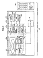
- the optical disc reading device 20 is configured as shown in FIG 1.
- the optical disc reading device 20 is comprised of an optical pickup device 10, a spindle motor 21, a transferring control unit 23, a loading motor 22, a control board 26 and a power unit 24.
- the optical pickup device 10 reads data recorded at the optical disc 100.
- the spindle motor 21 rotates the optical disc 100.
- the loading motor 22 loads a tray 20a whereon the optical disc 100 is placed.
- the control board 26 controls processing for reading data and recording data e.g..
- the power unit 24 supplies an electrical power.
- a remote control interface 26b receives an operation signal output from the remote control 25 and outputs the operation signal to a microcomputer 26a through a bus 26k.
- the microcomputer 26a accepts the operation signal, the loading motor 22 is driven for loading the tray 20a into the optical disc reading device 20.
- the microcomputer 26a drives the spindle motor 21 to rotate the optical disc 100.
- the microcomputer 26a selects a suitable obj ective lens of the optical pickup device 10 corresponding to the optical disc 100 which is going to be played.
- Hollows called pits are formed on a recording surface of the optical disc 100 and the optical pickup device 10 irradiates a laser beam to the pits and reads data by detecting the laser beam reflected by the optical disc 100. Then the transferring control unit 23 controls a position of the optical pickup device 10, and the optical pickup device 10 is controlled so as to follow the pits of the optical disc 100 on rotating.
- the laser beam irradiated to the optical disc 100 is reflected and outgoing through a route same as the incoming route to the optical disc 100.
- the laser beam 10 irradiated to the optical disc 100 is reflected by the optical disc 100.
- the laser beam 10 reflected by the optical disc 100 is detected by a detector and converted to digital video signals and digital sound signals.
- the digital video and sound signals are sent to the control board 26.
- the digital video signals are sent to a video reproduction unit 26e.
- the video reproduction unit 26e generates image data corresponding to every frame, the image data is sent to external equipment through an input / output [I/O] terminal 26d with temporarily buffering in a buffer memory 26f.
- the sound signals acquired by the control board 26 are converted to sound data by a sound generator 26g.
- the sound data is sent to external equipment through an input / output [I/O] terminal 26d and buffered in a buffer memory 26h.
- the video data and the sound data will be recorded at a hard disc drive [HDD] 26c of the optical disc reading device 20, the video data and the sound data buffered in the buffer memory 26f, 26h are written at predetermined addresses of the HDD 26c based on instructions by of the microcomputer 26a.
- FIG 2 is a block diagram of the optical pickup device 10.
- the optical pickup device 10 is configured for reading data by irradiating to the laser beam to the microscopic pits formed on the recording surface of the optical disc 100 and detecting the laser beam reflected by the pits.
- the pits are formed at a predetermined address area on the recording surface of the optical disc 100, the optical pickup device 10 have to accurately irradiate the laser beam to the pits by accurate transferring controlling of the optical pickup device 10.
- the optical pickup device 10 has a position controlling function (the transferring control unit 23 and a transferring controller 26i on the control board 26) for accurately irradiating and focusing the laser beam on the microscopic pits formed on the optical disc 100 rotated by the spindle motor 21. Further, the optical pickup device 10 has a function for adjusting the focal length and focal amount in order to playing each of different kinds of the optical discs 100 such like DVDs and CDs.
- the optical pickup device 10 is comprised of a laser diode 11, a couple of objective lenses 12a, 12b, a lens holder 13, an optical system 14, a position adjusting mechanism 15 and a detector 16.
- the laser diode 11 generates the laser beam.
- the objective lenses 12a, 12b focus the incoming laser beam.
- the lens holder 13 holds the objective lenses 12a, 12b.
- the optical system 14 reflects the laser beam from the laser diode 11 to irradiate the laser beam to the objective lenses 12a, 12b.
- the position adjusting mechanism 15 moves the lens holder 13 along a focusing direction perpendicular to the optical disc 100 and a tracking direction parallel to the optical disc 100 in order to follow the pits on rotating.
- the detector detects the laser beam reflected by the optical disc 100.
- the objective lenses 12a, 12b have different focal lengths and focal amounts. It can be possible to change the focal length and the focal amount corresponding to a kind of the optical discs by alternating the objective lenses 12a, 12b. Therefore, the optical pickup device 10 can read two or three kinds of the optical disc 100.
- the optical system 14 is comprised of a mirror 14a, a collimate lens 14b and a half mirror 14c.
- the laser beam irradiated by the laser diode 11 in transversal direction of FIG 2 is reflected to about 45 degree upper angle by the mirror 14a.
- the collimate lens 14b collimates the laser beam reflected by the mirror 14a.
- the half mirror 14c is arranged between the laser diode 11 and the mirror 14a. And the half mirror 14c gets through the laser beam irradiated by the laser diode 11 and reflects the laser beam reflected by the optical disc 100.
- the laser beam irradiated by the laser diode 11 is reflected to about 45 degree upper angle by the mirror 14a and irradiated to the collimate lens 14b.
- the laser beam irradiated to the collimate lens 14b is collimated and sent to the objective lenses 12a, 12b.
- the objective lenses 12a, 12b focus the laser beam on the pits formed on the optical disc 100.
- the position adjusting mechanism 15 adjusts the position of the lens holder 13 to irradiate the laser beam focused by the objective lenses 12a, 12b to the pits accurately.
- the position adjusting mechanism 15 uses a magnet for tracking, a coil for tracking, a magnet for focusing and a coil for focusing.
- the laser beam irradiated to the pits on the optical disc 100 is reflected at the pits and irradiated to the half mirror 14c through same route as the incoming route.
- the half mirror 14c irradiates the laser beam to the detector 15 by reflection.
- the detector 15 detects incoming laser beam from the half mirror 14c and converts the laser beam detection to digital video signals.
- the video signals are output to the control board 26.
- the detector 15 in the present invention uses photo diodes to convert the laser beam detection to the digital video signals. Further, if the optical disc 100 having the recording surface geometrically different from that of previous optical disc 100 will be played, the position adjusting mechanism 15 switches the objective lenses 12a, 12b to be used by moving the lens holder 13. These procedures are executed by processing of the microcomputer 26a and this processing also realizes each function of the optical pickup device 10.
- the objective lenses 12a, 12b are switched by the position adjusting mechanism 15 for changing the focal length and the focal amount for focusing the incoming laser beam.
- the changing the focal length and the focal amount of the incoming laser beam enables to play a plural of kinds of the optical discs like the DVDs and the CDs having different geometry of recording surfaces.
- the objective lenses 12a, 12b have to be assembled to keep being parallel each other during assembling, because the position adjusting mechanism 15 adjusts the position of the lens holder 13 with the objective lenses 12a, 12b as a whole. It's preferable that adjusting each angles of the objective lenses 12a, 12b can easily be done during the assembling them. Therefore, the optical pickup device 10 as the first embodiment of the present invention is configured to be easily adjusted each inclination angles of the objective lenses 12a, 12b.
- FIG 3 is a perspective view showing the configuration of the lens holder 13 of the embodiment of the present invention.
- the lens holder 13 is comprised of a body, a first lens housing portion 13a, a second lens housing portion 13b and a shaft-inserting hole 13c.
- the body is formed in a rectangular parallelepiped shape and the laser beam is incoming to upper plane of the body.
- the first lens housing portion 13a and the second lens housing portion 13b are formed in a hollow tubular shape and disposed at an edge of the upper plane of the body.
- the shaft-inserting hole 13c is inserted a shaft that functions as a horizontal rotating axis of the lens holder 13 when the position adjusting mechanism 15 adjusts the position of the lens holder 13.
- the coils (for tracking and focusing) of the position adjusting mechanism 15 are arranged on front plane and a bottom plane of the body.
- the first lens housing portion 13a has a first opening 13a1 and the second lens housing portion has a second opening 13b1.
- the openings 13a1, 13b1 are opening to upper direction where the laser beam is incoming.
- the objective lenses 12a, 12b are placed to the openings 13a1, 13b1. Radiated grooves are formed along circular edge of the openings 13a1, 13b1.
- the first objective lenses 12a is placed to the first opening 13a1
- the second objective lenses 12b is placed to the second opening 13b1.
- the inclination angle of the second objective lens 12b is adjusted to be substantially parallel to that of the first objective lenses 12a by using a spacer 13d. If the angles of the objective lenses 12a, 12b don't become substantially parallel each other, the angle of the second objective lens 12b is adjusted again by adjusting the spacer 13d. Therefore, the lens housing portions 13a, 13b and the spacer 13d have to be configured to make adjusting the inclination angle of the second objective lens 12b easy.
- the detail configuration of the lens housing portions 13a, 13b and the spacer 13d will be explained below.
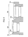
- FIG 4 is a cross sectional view of the lens holder 13 that mainly illustrates the lens housing portions 13a, 13b.
- the lens holder 13 has the lens housing portions 13a, 13b with the openings 13a1, 13b1 that are substantially parallel to the upper plane of the body.
- the lens housing portion 13a is comprised of a first seat 13a2 having a diameter that is different from a diameter of the first opening 13a1.
- the first objective lens 12a has a radially extended edge.
- the first objective lenses 12a is placed to the first lens housing portion 13a by being coupled a lower surface of the radially extended edge to the first seat 13a2.
- the second lens housing portion 13b has a second seat 13b2 that is formed at a position where is inward from the second opening 13b1 by a predetermined length.
- a diameter of the second seat 13b2 is wider than that of the first seat 13a1, the second objective lens 12b fixed by the spacer 13d is placed to the second lens housing portion 13b by placing lower surface of edge of the spacer 13 d on the, second seat 13b2.
- FIG. 5 is a perspective view showing the spacer 13d.
- the spacer 13d is comprised of a receiving plane 13d1, a third seat 13d2 and a couple of foot portions 13d3, 13d4.
- the spacer 13d is configured to be in a ring shape to be rotated in the second lens housing portion 13b.
- the receiving plane 13dl is formed in an aerial ring shape in transversal cross section.
- the second objective lens 12b is concentrically placed on the spacer 13d and the edge of the second objective lens 12b is supported by the third seat 13d2.
- the foot portions 13d3, 13d4 are configured to enable to adjust the inclination angle of the spacer 13d.
- the foot portions 13d3, 13d4 are arranged at radially opposite positions each other.
- the foot portions 13d3, 13d4 are vertically protruding below [aim to second seat 13b2] and the foot portions 13d3, 13d4 are triangular shape with slopes 13d5, 13d6 sloping to make peaks as the lowest portion of the foot portions 13d3, 13d4.
- the peaks of the foot portions 13d3, 13d4 work as fulcrums for tilting the spacer 13d.
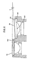
- FIG 6 is a vertical cross sectional view of the objective lenses 12a, 12b being placed to the lens holder 13.
- the inclination angle of the second objective lens 12b is slanted off the inclination angle of the first objective lens 12a by ⁇ in anticlockwise direction.
- the spacer 13d is rotated on the seat 13b2 to make a virtual straight line connecting the foot portions 13d3, 13d4 orthogonal to inclination direction of the first objective lens 12a.
- the inclination direction of the first objective lens 12a is a direction along a diameter connecting the highest point and the lowest point in the circular edge of the first objective lens 12a.
- the spacer 13d is tilted by ⁇ in clockwise direction with making the foot portions 13d3, 13d4 touching the seat 13d2 work as fulcrums. Therefore the spacer 13d can be tilted to make the inclination angle of the second objective lens 12b substantially parallel to that of the first objective lens 12a.
- the spacer 13d is fixed to second lens housing portion 13b by an adhesion bond. This leads that the second objective lens 12b is fixed at the inclination angle same as that of the first objective lens 12a.
- the second objective lens 12b can be adjusted its rotation angle by rotating the spacer 13d along the second opening 13b1 and adjusted its inclination angle by tilting the spacer 13d by making the foot portions 13d3, 13d4 work as fulcrums.
- High machining accuracy for making the lens holder 13 is not required, because geometrical variations of the lens housing portions 13a, 13b can be absorbed by tilting and rotating of the spacer 13d. Therefore the lens holder 13 can be made from even resin whose machining accuracy is worse than metal. And the lens holder 13 can be light because the lens holder 13 is made from the resin. Therefore, unwanted vibration of the lens holder 13 can be reduced.
- FIG 7 is a perspective view of the spacer in the second embodiment.
- the spacer 13d is shaped as explained below for easily forming the spacer 13d.
- the spacer 13d is a shape having foot portions 13d7, 13d8 protruding to lower direction from a receiving plane 13d1.
- the foot portions 13d7, 13d8 are formed rectangular shapes and allocated at radially opposite positions each other.
- the shape of the spacer 13d is simple and easy-to-make because of the rectangular shaped foot portions 13d7, 13d8.
- An object of the present invention is providing an optical pickup device and optical disc reading device using the optical pickup device that make adjustment angles of objective lenses easy without increasing weight of a lens holder.
- an optical pickup device of an aspect of the present invention is configured to be comprised of: a first objective lens focusing laser beam generated by a laser generator; a second objective lens focusing the laser beam with a focal length different from that of the first objective lens; a first lens housing portion having a first seat whereon the first objective lens is put; a second lens housing portion having a second seat that is substantially ring shape; a ring shaped spacer put on the second seat and holding the second objective lens; a couple of foot portions protruding to the second seat from radially opposite positions in the spacer.
- the second objective lens is holed by the spacer is placed to the second lens housing portion by putting the spacer on the second seat of the second lens housing portion with the foot portions supported by the second seat.
- the objective lens can be adjusted its angle by rotating the spacer along to the opening and tilting the spacer by using the foot portions as fulcrums.
- High machining accuracy for making the second lens housing portion is not required, because geometrical variations of the second lens housing portion can be absorbed by tilting and rotating the spacer. Therefore the second lens housing portion can be made from even resin whose machining accuracy is worse than metal.
- the second lens housing portion can be light because the second lens housing portion can be made from the resin. Therefore, unwanted vibration of the second lens housing portion can be reduced.
Landscapes
- Physics & Mathematics (AREA)
- Optics & Photonics (AREA)
- General Physics & Mathematics (AREA)
- Optical Head (AREA)
Abstract
The present invention discloses an optical pickup device comprising: a first objective lens focusing laser beam generated by a laser generator; a second objective lens focusing the laser beam with a focal length different from that of the first objective lens; a first lens holding portion having a first seat whereon the first objective lens is put; a second lens holding portion having a second seat that is substantially ring shape; a ring shaped spacer put on the second seat and holding the second objective lens; a couple of foot portions protruding to the second seat from radially opposite positions in the spacer.
Description
- The present invention relates to an optical pickup device and optical disc reading device. Especially the present invention relates to an optical pickup device and an optical disc reading device that read data recorded at plural kinds of optical discs by using two objective lenses.
- An optical pickup device described blow is known as a technology for reading data form optical discs like Digital Versatile Discs [DVDs] and compact discs [CDs]. The optical pickup device is shown in FIG 8. According to the FIG 8, the optical pickup device 1 is comprised of a
laser diode 2 as a laser beam generator, ahalf mirror 3 that transmits the laser beam irradiated by thelaser diode 2 and reflects the laser beam reflected by the optical disc, amirror 4 that reflects the laser beam irradiated by thelaser diode 2 to a predetermined angle, acollimate lens 5 that collimates the laser beam reflected by themirror 4 and aobjective lens 6 that focuses the laser beam collimated by thecollimate lens 5 on theoptical disc 100. - According to the optical pickup device 1, the laser beam irradiated by the
laser diode 2 is reflected at themirror 4 and irradiated to theobjective lens 6. Theobjective lens 6 focuses incoming laser beam on a reading surface of theoptical disc 100 with predetermined focal length. Pits are formed on the reading surface of theoptical disc 100, the laser beam incoming to the pits is reflected and irradiated to thehalf mirror 3 through substantially same route that is substantially identical to the incoming route. And thehalf mirror 3 reflects the laser beam incoming and sends the laser beam to adetector 7. Thedetector 7 detects the laser beam and reads data based on detections of the laser beam. Therefore it is required that a distance between theobjective lens 6 and theoptical disc 100 is identical to a focal length of theobjective lens 6, in order to accurately focus the laser beam from the irradiator on the pits formed on the reading surface of theoptical disc 100. - There are variations of sizes of the pits and positions of the pits on the reading surface in the DVDs and the CDs. Therefore, the focal length has to be adjusted corresponding to the variations. In
JP-A No.H11-259891 - In this optical pickup device 1, in case the first objective lens 8a1 is used for reading the DVDs and the second objective lens 8a2 is used for reading the CDs, when the optical pickup device 1 reads the CDs, the optical pickup device 1 makes a movable part (not shown in FIG 9) move to transfer the lens holder 8b in order to make the laser beam from the laser beam generator be irradiated to the second objective lens 8a2. When the optical pickup device 1 reads the DVDs, the optical pickup device 1 makes the movable part move to transfer the lens holder 8b in order to make the laser beam from the laser beam generator be irradiated to the first objective lens 8a1. Then each of the focal length of the first and second lenses 8a1, 8a2 to the CDs and the DVDs is adjusted by transferring whole lens holder 8b. In particular each of the focal length of the first objective lens 8a1 and the second objective lens 8a2 is adjusted by controlling the focal length of the first lens 8a1. Therefore, the first objective lens 8a1 and the second objective lens 8a2 put on the lens holder 8b have to be adjusted to be parallel each other.
- The adjustment mentioned above is achieved by tilting one of the first objective lens 8 a1 and the second objective lens 8a2 to be parallel to the other one by a jig e.g. with measuring a tilting angle by an autocollimator e.g.. This adjustment is time consuming because sufficient accuracy is required. After the tilting, the first objective lens 8a1 and the second objective lens 8a2 are fixed to the lens holder 8b by an adhesion bond.
-
JP-ANo.2005-174485 - And
JP-A.No.H10-154342 - The invention of
JP-ANo.2005-174485 - And the invention of
JP-A No.H10-154342 - An object of the present invention is providing an optical pickup device and optical disc reading device using the optical pickup device that make adjustment angles of objective lenses easy without increasing weight of a lens holder.
- To achieve the object, an optical pickup device of an aspect of the present invention is configured to be comprised of: a first objective lens focusing laser beam generated by a laser generator; a second objective lens focusing the laser beam with a focal length different from that of the first objective lens; a first lens holding portion having a first seat whereon the first objective lens is placed; a second lens holding portion having a second seat that is substantially in a ring shape; a ring shaped spacer placed on the second seat and holding the second objective lens; a couple of foot portions protruding to the second seat from radially opposite positions in the spacer.
- According to the configuration mentioned above, the second objective lens is holed by the spacer is placed to the second lens holding portion by putting the spacer on the second seat of the second lens holding portion with the foot portions supported by the second seat. The objective lens can be adjusted its angle by rotating the spacer along to the opening and tilting the spacer by utilizing the foot portions as fulcrums. High machining accuracy for making the second lens holding portion is not required, because geometrical variations of the second lens holding portion can be absorbed by tilting and rotating the spacer. Therefore the second lens holding portion can be made from even resin whose machining accuracy is worse than metal. And the second lens holding portion can be light because the second lens holding portion can be made from the resin. Therefore, unwanted vibration of the second lens holding portion can be reduced.
- Another aspect of the present invention discloses an optical pickup device wherein: the second lens holding portion, the spacer and the second objective lens are concentrically placed.
- An optional aspect of the present invention discloses an optical pickup device wherein: each of the foot portions is in a substantially triangular shape.
- Another aspect of the present invention discloses an optical pickup device as wherein: each of the foot portions is in a substantially rectangular shape.
- Another aspect of the present invention discloses an optical pickup device wherein: the spacer, the first lens holding portion and the second lens holding portion are made from resin.
- A concrete aspect of the present invention discloses an optical disc reading device comprising: a laser diode generating laser beam; a first objective lens focusing the laser beam generated by the laser diode and irradiating the laser beam to a recording surface of an optical disc; a second objective lens focusing the laser beam with a focal length different from that of the first objective lens and irradiating the laser beam to the recording surface of the optical disc; an optical system irradiating the laser beam from the laser diode to one of the first objective lens and second objective lens; a detector detecting the laser beam reflected by the recording surface of the optical disc and converting a result of the laser beam detection to digital signals; a lens holder made from resin and formed in a substantially rectangular parallelepiped shape with a upper plane receiving the laser beam; a first lens holding portion made from resin and formed in a substantially tubular shape with a first opening parallel to the upper plane and with a first seat whereon the first objective lens is placed; a second lens holding portion made from resin and formed in a substantially tubular shape with a second opening parallel to the upper plane and with a second seat that is substantially in a ring shape; a ring shaped spacer made from resin concentrically placed on the second seat and concentrically holding the second objective lens; a couple of triangular foot portions protruding to the second seat from radially opposite positions in the spacer and working as fulcrums for tilting the spacer to make the second objective lens parallel to the first objective lens.
- These and other features, aspects, and advantages of the invention will be apparent to those skilled in the art from the following detailed description of preferred non-limiting exemplary embodiments, taken together with the drawings and the claims that follow.
- It is to be understood that the drawings are to be used for the purposes of exemplary illustration only and not as a definition of the limits of the invention. Throughout the disclosure, the word "exemplary" is used exclusively to mean "serving as an example, instance, or illustration." Any embodiment described as "exemplary" is not necessarily to be construed as preferred or advantageous over other embodiments.
Referring to the drawings in which like reference character(s) present corresponding parts throughout: -
- FIG 1 is an exemplary diagram showing a block configuration of an optical disc reading device according to the present invention;
- FIG 2 is an exemplary diagram showing a block configuration of an optical pickup device;
- FIG 3 is an exemplary perspective view showing a lens holder;
- FIG 4 is an exemplary cross sectional view of the lens holder;
- FIG 5 is an exemplary perspective view showing a spacer;
- FIG 6 is an exemplary cross sectional view of a first and second objective lenses placed into a lens holder,
- FIG 7 is an exemplary perspective view showing a spacer of second embodiment;
- FIG 8 is an exemplary block diagram of a related optical pickup device; and
- FIG 9 is an exemplary perspective view showing a related head unit arranged a couple of objective lenses.
- The detailed description set forth below in connection with the appended drawings is intended as a description of presently preferred embodiments of the invention and is not intended to represent the only forms in which the present invention may be constructed and/or utilized.
- As a detailed example of an optical pickup device according to the present invention, an optical disc reading device using the optical pickup device is explained. However, the optical pickup device according to the present invention can be not only used in the optical disc reading device but also applied to whatever the optical pickup device is utilized. Embodiments of the present invention will be explained according to an order mentioned below.
- A. First embodiment
- B. Summary of the first embodiment
- C. Second embodiment
- D. Summary of the second embodiment
- In what follows, an outline of components and functions of an optical disc reading device realizing the present invention is explained with referencing FIG 1, 2, 3, 4, 5 and 6. The optical disc reading device is used for reading data recorded at optical discs such like DVDs and CDs. The optical
disc reading device 20 is configured as shown in FIG 1. In FIG 1 the opticaldisc reading device 20 is comprised of anoptical pickup device 10, aspindle motor 21, a transferringcontrol unit 23, aloading motor 22, acontrol board 26 and apower unit 24. Theoptical pickup device 10 reads data recorded at theoptical disc 100. Thespindle motor 21 rotates theoptical disc 100. The loading motor 22 loads atray 20a whereon theoptical disc 100 is placed. Thecontrol board 26 controls processing for reading data and recording data e.g.. Thepower unit 24 supplies an electrical power. - According to the configuration described above, when a
remote control 25 is operated.with placing theoptical disc 100 on thetray 20a to play the optical disc.100, aremote control interface 26b receives an operation signal output from theremote control 25 and outputs the operation signal to amicrocomputer 26a through abus 26k. When themicrocomputer 26a accepts the operation signal, the loadingmotor 22 is driven for loading thetray 20a into the opticaldisc reading device 20. Next, themicrocomputer 26a drives thespindle motor 21 to rotate theoptical disc 100.
Further, themicrocomputer 26a selects a suitable obj ective lens of theoptical pickup device 10 corresponding to theoptical disc 100 which is going to be played. - Hollows called pits are formed on a recording surface of the
optical disc 100 and theoptical pickup device 10 irradiates a laser beam to the pits and reads data by detecting the laser beam reflected by theoptical disc 100. Then the transferringcontrol unit 23 controls a position of theoptical pickup device 10, and theoptical pickup device 10 is controlled so as to follow the pits of theoptical disc 100 on rotating. The laser beam irradiated to theoptical disc 100 is reflected and outgoing through a route same as the incoming route to theoptical disc 100. Thelaser beam 10 irradiated to theoptical disc 100 is reflected by theoptical disc 100. And thelaser beam 10 reflected by theoptical disc 100 is detected by a detector and converted to digital video signals and digital sound signals. The digital video and sound signals are sent to thecontrol board 26. In this specification, detailed explanations for data playing and data recording by thecontrol board 26 are omitted because they are well known technologies. The digital video signals are sent to avideo reproduction unit 26e. Thevideo reproduction unit 26e generates image data corresponding to every frame, the image data is sent to external equipment through an input / output [I/O] terminal 26d with temporarily buffering in abuffer memory 26f. - At the same time, the sound signals acquired by the
control board 26 are converted to sound data by asound generator 26g. In the same manner, the sound data is sent to external equipment through an input / output [I/O] terminal 26d and buffered in a buffer memory 26h. Further if the video data and the sound data will be recorded at a hard disc drive [HDD] 26c of the opticaldisc reading device 20, the video data and the sound data buffered in thebuffer memory 26f, 26h are written at predetermined addresses of theHDD 26c based on instructions by of themicrocomputer 26a. - A configuration of the
optical pickup device 10 will be explained below. FIG 2 is a block diagram of theoptical pickup device 10. Theoptical pickup device 10 is configured for reading data by irradiating to the laser beam to the microscopic pits formed on the recording surface of theoptical disc 100 and detecting the laser beam reflected by the pits. The pits are formed at a predetermined address area on the recording surface of theoptical disc 100, theoptical pickup device 10 have to accurately irradiate the laser beam to the pits by accurate transferring controlling of theoptical pickup device 10. Therefore theoptical pickup device 10 has a position controlling function (the transferringcontrol unit 23 and a transferringcontroller 26i on the control board 26) for accurately irradiating and focusing the laser beam on the microscopic pits formed on theoptical disc 100 rotated by thespindle motor 21. Further, theoptical pickup device 10 has a function for adjusting the focal length and focal amount in order to playing each of different kinds of theoptical discs 100 such like DVDs and CDs. - To realize the functions of the
optical pickup device 10, theoptical pickup device 10 is comprised of alaser diode 11, a couple ofobjective lenses lens holder 13, an optical system 14, aposition adjusting mechanism 15 and a detector 16. Thelaser diode 11 generates the laser beam. Theobjective lenses lens holder 13 holds theobjective lenses laser diode 11 to irradiate the laser beam to theobjective lenses position adjusting mechanism 15 moves thelens holder 13 along a focusing direction perpendicular to theoptical disc 100 and a tracking direction parallel to theoptical disc 100 in order to follow the pits on rotating. Therefore, it is possible to accurately irradiate the laser beam to the rotating pits. The detector detects the laser beam reflected by theoptical disc 100. Theobjective lenses objective lenses optical pickup device 10 can read two or three kinds of theoptical disc 100. - Further, the optical system 14 is comprised of a
mirror 14a, acollimate lens 14b and ahalf mirror 14c. The laser beam irradiated by thelaser diode 11 in transversal direction of FIG 2 is reflected to about 45 degree upper angle by themirror 14a. Thecollimate lens 14b collimates the laser beam reflected by themirror 14a. Thehalf mirror 14c is arranged between thelaser diode 11 and themirror 14a. And thehalf mirror 14c gets through the laser beam irradiated by thelaser diode 11 and reflects the laser beam reflected by theoptical disc 100. According to this configuration, the laser beam irradiated by thelaser diode 11 is reflected to about 45 degree upper angle by themirror 14a and irradiated to thecollimate lens 14b. The laser beam irradiated to thecollimate lens 14b is collimated and sent to theobjective lenses objective lenses optical disc 100. Then theposition adjusting mechanism 15 adjusts the position of thelens holder 13 to irradiate the laser beam focused by theobjective lenses position adjusting mechanism 15 adjust the position of thelens holder 13, theposition adjusting mechanism 15 uses a magnet for tracking, a coil for tracking, a magnet for focusing and a coil for focusing. - The laser beam irradiated to the pits on the
optical disc 100 is reflected at the pits and irradiated to thehalf mirror 14c through same route as the incoming route. Thehalf mirror 14c irradiates the laser beam to thedetector 15 by reflection. Thedetector 15 detects incoming laser beam from thehalf mirror 14c and converts the laser beam detection to digital video signals. The video signals are output to thecontrol board 26. Thedetector 15 in the present invention uses photo diodes to convert the laser beam detection to the digital video signals. Further, if theoptical disc 100 having the recording surface geometrically different from that of previousoptical disc 100 will be played, theposition adjusting mechanism 15 switches theobjective lenses lens holder 13. These procedures are executed by processing of themicrocomputer 26a and this processing also realizes each function of theoptical pickup device 10. - As explained above, the
objective lenses position adjusting mechanism 15 for changing the focal length and the focal amount for focusing the incoming laser beam. The changing the focal length and the focal amount of the incoming laser beam enables to play a plural of kinds of the optical discs like the DVDs and the CDs having different geometry of recording surfaces. Theobjective lenses position adjusting mechanism 15 adjusts the position of thelens holder 13 with theobjective lenses objective lenses optical pickup device 10 as the first embodiment of the present invention is configured to be easily adjusted each inclination angles of theobjective lenses - The configuration of the
lens holder 13 will be explained below. FIG 3 is a perspective view showing the configuration of thelens holder 13 of the embodiment of the present invention. Thelens holder 13 is comprised of a body, a firstlens housing portion 13a, a secondlens housing portion 13b and a shaft-insertinghole 13c. The body is formed in a rectangular parallelepiped shape and the laser beam is incoming to upper plane of the body. The firstlens housing portion 13a and the secondlens housing portion 13b are formed in a hollow tubular shape and disposed at an edge of the upper plane of the body. The shaft-insertinghole 13c is inserted a shaft that functions as a horizontal rotating axis of thelens holder 13 when theposition adjusting mechanism 15 adjusts the position of thelens holder 13. The coils (for tracking and focusing) of theposition adjusting mechanism 15 are arranged on front plane and a bottom plane of the body. The firstlens housing portion 13a has a first opening 13a1 and the second lens housing portion has a second opening 13b1. The openings 13a1, 13b1 are opening to upper direction where the laser beam is incoming. Theobjective lenses - The first
objective lenses 12a is placed to the first opening 13a1, the secondobjective lenses 12b is placed to the second opening 13b1. Then the inclination angle of the secondobjective lens 12b is adjusted to be substantially parallel to that of the firstobjective lenses 12a by using aspacer 13d. If the angles of theobjective lenses objective lens 12b is adjusted again by adjusting thespacer 13d. Therefore, thelens housing portions spacer 13d have to be configured to make adjusting the inclination angle of the secondobjective lens 12b easy. The detail configuration of thelens housing portions spacer 13d will be explained below. - FIG 4 is a cross sectional view of the
lens holder 13 that mainly illustrates thelens housing portions lens holder 13 has thelens housing portions lens housing portion 13a is comprised of a first seat 13a2 having a diameter that is different from a diameter of the first opening 13a1. The firstobjective lens 12a has a radially extended edge. The firstobjective lenses 12a is placed to the firstlens housing portion 13a by being coupled a lower surface of the radially extended edge to the first seat 13a2. On the other hand, the secondlens housing portion 13b has a second seat 13b2 that is formed at a position where is inward from the second opening 13b1 by a predetermined length. A diameter of the second seat 13b2 is wider than that of the first seat 13a1, the secondobjective lens 12b fixed by thespacer 13d is placed to the secondlens housing portion 13b by placing lower surface of edge of thespacer 13 d on the, second seat 13b2. - The
spacer 13d is configured to enable to adjust the inclination angle of the secondobjective lens 12b. FIG. 5 is a perspective view showing thespacer 13d. In FIG 5 thespacer 13d is comprised of a receiving plane 13d1, a third seat 13d2 and a couple of foot portions 13d3, 13d4. Thespacer 13d is configured to be in a ring shape to be rotated in the secondlens housing portion 13b. The receiving plane 13dl is formed in an aerial ring shape in transversal cross section. The secondobjective lens 12b is concentrically placed on thespacer 13d and the edge of the secondobjective lens 12b is supported by the third seat 13d2. The foot portions 13d3, 13d4 are configured to enable to adjust the inclination angle of thespacer 13d. Thus the foot portions 13d3, 13d4 are arranged at radially opposite positions each other. In a transversal side view of thespacer 13d, the foot portions 13d3, 13d4 are vertically protruding below [aim to second seat 13b2] and the foot portions 13d3, 13d4 are triangular shape with slopes 13d5, 13d6 sloping to make peaks as the lowest portion of the foot portions 13d3, 13d4. When the foot portions 13d3, 13d4 are placed on the second seat 13b2, the peaks of the foot portions 13d3, 13d4 work as fulcrums for tilting thespacer 13d. - A method for adjusting the angle of the second
objective lens 12b by tilting thespacer 13d will be explained below. According the method, thespacer 13d is provisionally fixed by a jig for adjusting with measuring the angle of the secondobjective lens 12b by a measurement apparatus like an autocollimator. Whatever can hold thespacer 13d and make thespacer 13d tilt and rotate as described below can be used as the jig. FIG 6 is a vertical cross sectional view of theobjective lenses lens holder 13. In the FIG 6, the inclination angle of the secondobjective lens 12b is slanted off the inclination angle of the firstobjective lens 12a by α in anticlockwise direction. - Therefore a method described below is executed for adjusting the inclination angle of the second
objective lens 12b. First thespacer 13d is rotated on the seat 13b2 to make a virtual straight line connecting the foot portions 13d3, 13d4 orthogonal to inclination direction of the firstobjective lens 12a. The inclination direction of the firstobjective lens 12a is a direction along a diameter connecting the highest point and the lowest point in the circular edge of the firstobjective lens 12a. Next thespacer 13d is tilted by α in clockwise direction with making the foot portions 13d3, 13d4 touching the seat 13d2 work as fulcrums. Therefore thespacer 13d can be tilted to make the inclination angle of the secondobjective lens 12b substantially parallel to that of the firstobjective lens 12a. In this state, thespacer 13d is fixed to secondlens housing portion 13b by an adhesion bond. This leads that the secondobjective lens 12b is fixed at the inclination angle same as that of the firstobjective lens 12a. - As described above, according to the
optical pickup device 10 of this embodiment, the secondobjective lens 12b can be adjusted its rotation angle by rotating thespacer 13d along the second opening 13b1 and adjusted its inclination angle by tilting thespacer 13d by making the foot portions 13d3, 13d4 work as fulcrums. High machining accuracy for making thelens holder 13 is not required, because geometrical variations of thelens housing portions spacer 13d. Therefore thelens holder 13 can be made from even resin whose machining accuracy is worse than metal. And thelens holder 13 can be light because thelens holder 13 is made from the resin. Therefore, unwanted vibration of thelens holder 13 can be reduced. - Optical pickup device of the second embodiment realizing the present invention will be explained below. FIG 7 is a perspective view of the spacer in the second embodiment. In the second embodiment the
spacer 13d is shaped as explained below for easily forming thespacer 13d. Thespacer 13d is a shape having foot portions 13d7, 13d8 protruding to lower direction from a receiving plane 13d1. The foot portions 13d7, 13d8 are formed rectangular shapes and allocated at radially opposite positions each other. When the secondobjective lens 12b fixed to thespacer 13d is attached to the secondlens housing portion 13b, thespacer 13d can be tilted by using the foot portions 13d3, 13d4 as fulcrums like thespacer 13d of the first embodiment. - As described above, according to the
optical pickup device 10 of this embodiment, advantages same as that of the first embodiment can be obtained, further another advantage described below can be obtained. That is, the shape of thespacer 13d is simple and easy-to-make because of the rectangular shaped foot portions 13d7, 13d8. - An object of the present invention is providing an optical pickup device and optical disc reading device using the optical pickup device that make adjustment angles of objective lenses easy without increasing weight of a lens holder.
- To achieve the object, an optical pickup device of an aspect of the present invention is configured to be comprised of: a first objective lens focusing laser beam generated by a laser generator; a second objective lens focusing the laser beam with a focal length different from that of the first objective lens; a first lens housing portion having a first seat whereon the first objective lens is put; a second lens housing portion having a second seat that is substantially ring shape; a ring shaped spacer put on the second seat and holding the second objective lens; a couple of foot portions protruding to the second seat from radially opposite positions in the spacer.
- According to the configuration mentioned above, the second objective lens is holed by the spacer is placed to the second lens housing portion by putting the spacer on the second seat of the second lens housing portion with the foot portions supported by the second seat. The objective lens can be adjusted its angle by rotating the spacer along to the opening and tilting the spacer by using the foot portions as fulcrums. High machining accuracy for making the second lens housing portion is not required, because geometrical variations of the second lens housing portion can be absorbed by tilting and rotating the spacer. Therefore the second lens housing portion can be made from even resin whose machining accuracy is worse than metal. And the second lens housing portion can be light because the second lens housing portion can be made from the resin. Therefore, unwanted vibration of the second lens housing portion can be reduced.
- It is needless to say that the present invention is not limited to the embodiments described above, and for those skilled in the art the following are to be disclosed as embodiments of the present invention:
- Appropriately modified combination of mutually replaceable members, configurations, or the like which are disclosed in the above embodiments;
- Appropriately replaced or modified combination of members and configurations which are mutually replaceable with the members and configurations that are not disclosed in the above embodiment but are known arts; and
- Appropriately replaced or modified combination of members and configurations which can be assumed to be substitutions for the members and configuration that are not disclosed in the above embodiments but are disclosed in the above embodiments by those skilled in the art based on the known arts or the like.
Claims (6)
- An optical disc reading device having a laser diode generating laser beam, a first objective lens focusing the laser beam generated by the laser diode and irradiating the laser beam to a recording surface of an optical disc, a second objective lens focusing the laser beam with a focal length different from that of the first objective lens and irradiating the laser beam to the recording surface of the optical disc, an optical system irradiating the laser beam from the laser diode to one of the first objective lens and second objective lens and a detector detecting the laser beam reflected by the recording surface of the optical disc and converting a result of the laser beam detection to digital signals characterized by comprising:a lens holder made from resin and formed in a substantially rectangular parallelepiped shape with a upper plane receiving the laser beam;a first lens holding portion made from resin and formed in a substantially tubular shape with a first opening parallel to the upper plane and with a first seat whereon the first objective lens is placed;a second lens holding portion made from resin and formed in a substantially tubular shape with a second opening parallel to the upper plane and with a second seat that is substantially in a ring shape;a ring shaped spacer made from resin concentrically placed on the second seat and concentrically holding the second objective lens;a couple of triangular foot portions protruding to the second seat from radially opposite positions in the spacer and working as fulcrums for tilting the spacer to make the second objective lens parallel to the first objective lens.
- An optical pickup device having a first objective lens focusing laser beam generated by a laser generator and a second objective lens focusing the laser beam with a focal length different from that of the first objective lens characterized by comprising:a first lens holding portion having a first seat whereon the first objective lens is placed;a second lens holding portion having a second seat that is substantially in a ring shape;a ring shaped spacer placed on the second seat and holding the second objective lens;a couple of foot portions protruding to the second seat from radially opposite positions in the spacer.
- An optical pickup device according to claim 2 characterized in that:the second lens holding portion, the spacer and the second objective lens are concentrically placed.
- An optical pickup device according to claim 2 or 3 characterized in that:each of the foot portions is in a substantially triangular shape.
- An optical pickup device according to claim 2 or 3 characterized in that:each of the foot portions is in a substantially rectangular shape.
- An optical pickup device according to claim 2 through 5 characterized in that:the spacer, the first lens holding portion and the second lens holding portion are made from resin.
Applications Claiming Priority (1)
| Application Number | Priority Date | Filing Date | Title |
|---|---|---|---|
| JP2006233646A JP2008059661A (en) | 2006-08-30 | 2006-08-30 | Optical pickup device and optical disk reading device |
Publications (1)
| Publication Number | Publication Date |
|---|---|
| EP1895532A1 true EP1895532A1 (en) | 2008-03-05 |
Family
ID=38596909
Family Applications (1)
| Application Number | Title | Priority Date | Filing Date |
|---|---|---|---|
| EP07016589A Withdrawn EP1895532A1 (en) | 2006-08-30 | 2007-08-23 | Optical pickup device and optical disc reading device |
Country Status (4)
| Country | Link |
|---|---|
| US (1) | US20080056076A1 (en) |
| EP (1) | EP1895532A1 (en) |
| JP (1) | JP2008059661A (en) |
| CN (1) | CN101136223A (en) |
Families Citing this family (1)
| Publication number | Priority date | Publication date | Assignee | Title |
|---|---|---|---|---|
| CN103424840B (en) * | 2012-05-14 | 2016-01-13 | 信泰光学(深圳)有限公司 | The camera lens of tiltable adjustment |
Citations (5)
| Publication number | Priority date | Publication date | Assignee | Title |
|---|---|---|---|---|
| US5532987A (en) * | 1992-08-20 | 1996-07-02 | Mitsubishi Denki Kabushiki Kaisha | Focus error detecting device |
| JPH1011765A (en) * | 1996-06-26 | 1998-01-16 | Sharp Corp | Optical disc apparatus and method for adjusting tilt of objective lens thereof |
| US20050007906A1 (en) * | 2003-07-07 | 2005-01-13 | Matsushita Electric Industrial Co., Ltd. | Objective lens, optical pick-up device, and optical disk device |
| EP1612778A2 (en) * | 2004-06-29 | 2006-01-04 | Samsung Electronics Co., Ltd. | Optical pickup and apparatus and method for assembling a plurality of lenses |
| US20060018214A1 (en) * | 2004-07-21 | 2006-01-26 | Konica Minolta Opto, Inc. | Assembly method of optical pickup and optical pickup apparatus |
Family Cites Families (11)
| Publication number | Priority date | Publication date | Assignee | Title |
|---|---|---|---|---|
| US4772346A (en) * | 1986-02-14 | 1988-09-20 | International Business Machines Corporation | Method of bonding inorganic particulate material |
| US4793416A (en) * | 1987-06-30 | 1988-12-27 | Mobile Oil Corporation | Organic crosslinking of polymers for CO2 flooding profile control |
| JPH09288835A (en) * | 1996-02-23 | 1997-11-04 | Matsushita Electric Ind Co Ltd | Objective lens drive |
| US6392819B1 (en) * | 1999-05-11 | 2002-05-21 | Sharp Kabushiki Kaisha | Objective lens and fabrication method thereof |
| JP2001084685A (en) * | 1999-09-13 | 2001-03-30 | Clarion Co Ltd | Disk device tilt adjustment device |
| JP2003066300A (en) * | 2001-08-29 | 2003-03-05 | Sony Corp | Objective lens manufacturing apparatus and objective lens manufacturing method |
| KR100911141B1 (en) * | 2002-09-03 | 2009-08-06 | 삼성전자주식회사 | Lens and optical pickup with wavefront aberration correction function according to tilt |
| KR100509493B1 (en) * | 2003-02-26 | 2005-08-22 | 삼성전자주식회사 | Compatible optical pickup |
| US7114570B2 (en) * | 2003-04-07 | 2006-10-03 | Halliburton Energy Services, Inc. | Methods and compositions for stabilizing unconsolidated subterranean formations |
| US7063151B2 (en) * | 2004-03-05 | 2006-06-20 | Halliburton Energy Services, Inc. | Methods of preparing and using coated particulates |
| JP2008032768A (en) * | 2006-07-26 | 2008-02-14 | Matsushita Electric Ind Co Ltd | Lens actuator |
-
2006
- 2006-08-30 JP JP2006233646A patent/JP2008059661A/en active Pending
-
2007
- 2007-08-23 EP EP07016589A patent/EP1895532A1/en not_active Withdrawn
- 2007-08-29 CN CNA2007101485620A patent/CN101136223A/en active Pending
- 2007-08-30 US US11/897,509 patent/US20080056076A1/en not_active Abandoned
Patent Citations (5)
| Publication number | Priority date | Publication date | Assignee | Title |
|---|---|---|---|---|
| US5532987A (en) * | 1992-08-20 | 1996-07-02 | Mitsubishi Denki Kabushiki Kaisha | Focus error detecting device |
| JPH1011765A (en) * | 1996-06-26 | 1998-01-16 | Sharp Corp | Optical disc apparatus and method for adjusting tilt of objective lens thereof |
| US20050007906A1 (en) * | 2003-07-07 | 2005-01-13 | Matsushita Electric Industrial Co., Ltd. | Objective lens, optical pick-up device, and optical disk device |
| EP1612778A2 (en) * | 2004-06-29 | 2006-01-04 | Samsung Electronics Co., Ltd. | Optical pickup and apparatus and method for assembling a plurality of lenses |
| US20060018214A1 (en) * | 2004-07-21 | 2006-01-26 | Konica Minolta Opto, Inc. | Assembly method of optical pickup and optical pickup apparatus |
Also Published As
| Publication number | Publication date |
|---|---|
| JP2008059661A (en) | 2008-03-13 |
| CN101136223A (en) | 2008-03-05 |
| US20080056076A1 (en) | 2008-03-06 |
Similar Documents
| Publication | Publication Date | Title |
|---|---|---|
| JP4840167B2 (en) | Optical disk device | |
| US20080056076A1 (en) | Optical pickup device and optical disc reading device | |
| JP4289388B2 (en) | Optical pickup and optical disc apparatus | |
| JP2004318934A (en) | Optical disk device, its tilt control method, and tilt control program | |
| WO2006072843A1 (en) | Method and device for automatic disc skew correction | |
| US20050265137A1 (en) | Disc drive apparatus | |
| US7203137B2 (en) | Optical pickup unit and optical disc device | |
| JP2003228852A (en) | Optical pickup | |
| KR100624626B1 (en) | Optical disc device and sliding movement drive mechanism of optical pickup thereof | |
| JP4155266B2 (en) | Optical pickup angle and distance adjustment method | |
| JP2001126286A (en) | Optical pickup and disk drive device | |
| JP2815725B2 (en) | Optical pickup | |
| KR20050032576A (en) | Disc drive apparatus | |
| US8102738B2 (en) | Optical pickup and optical disk apparatus | |
| JP2006147113A (en) | Position adjusting device and position adjusting method | |
| JP2001134975A (en) | Objective lens for optical disk | |
| JP2003196866A (en) | Optical pickup device | |
| JPH05166210A (en) | Optical head | |
| JPH05225579A (en) | Optical disk device | |
| JP2006202427A (en) | Height position adjusting device of optical pickup | |
| JP2005216381A (en) | Optical pickup and optical disc apparatus | |
| JP2004103193A (en) | Optical pickup device and optical disk device using this optical pickup device | |
| JPH11213415A (en) | Optical pickup tilt adjustment mechanism | |
| JP2006134459A (en) | Optical pickup, optical disc apparatus, and skew sensor adjusting method | |
| JP2004326896A (en) | Optical pickup |
Legal Events
| Date | Code | Title | Description |
|---|---|---|---|
| PUAI | Public reference made under article 153(3) epc to a published international application that has entered the european phase |
Free format text: ORIGINAL CODE: 0009012 |
|
| AK | Designated contracting states |
Kind code of ref document: A1 Designated state(s): AT BE BG CH CY CZ DE DK EE ES FI FR GB GR HU IE IS IT LI LT LU LV MC MT NL PL PT RO SE SI SK TR |
|
| AX | Request for extension of the european patent |
Extension state: AL BA HR MK YU |
|
| AKX | Designation fees paid | ||
| STAA | Information on the status of an ep patent application or granted ep patent |
Free format text: STATUS: THE APPLICATION IS DEEMED TO BE WITHDRAWN |
|
| 18D | Application deemed to be withdrawn |
Effective date: 20080906 |
|
| REG | Reference to a national code |
Ref country code: DE Ref legal event code: 8566 |