EP1895481A2 - Bill validator - Google Patents
Bill validator Download PDFInfo
- Publication number
- EP1895481A2 EP1895481A2 EP07113730A EP07113730A EP1895481A2 EP 1895481 A2 EP1895481 A2 EP 1895481A2 EP 07113730 A EP07113730 A EP 07113730A EP 07113730 A EP07113730 A EP 07113730A EP 1895481 A2 EP1895481 A2 EP 1895481A2
- Authority
- EP
- European Patent Office
- Prior art keywords
- bill
- light
- ports
- light transmitting
- port
- Prior art date
- Legal status (The legal status is an assumption and is not a legal conclusion. Google has not performed a legal analysis and makes no representation as to the accuracy of the status listed.)
- Withdrawn
Links
Images




Classifications
-
- G—PHYSICS
- G07—CHECKING-DEVICES
- G07F—COIN-FREED OR LIKE APPARATUS
- G07F9/00—Details other than those peculiar to special kinds or types of apparatus
-
- G—PHYSICS
- G07—CHECKING-DEVICES
- G07D—HANDLING OF COINS OR VALUABLE PAPERS, e.g. TESTING, SORTING BY DENOMINATIONS, COUNTING, DISPENSING, CHANGING OR DEPOSITING
- G07D11/00—Devices accepting coins; Devices accepting, dispensing, sorting or counting valuable papers
- G07D11/10—Mechanical details
- G07D11/14—Inlet or outlet ports
-
- G—PHYSICS
- G07—CHECKING-DEVICES
- G07D—HANDLING OF COINS OR VALUABLE PAPERS, e.g. TESTING, SORTING BY DENOMINATIONS, COUNTING, DISPENSING, CHANGING OR DEPOSITING
- G07D11/00—Devices accepting coins; Devices accepting, dispensing, sorting or counting valuable papers
- G07D11/20—Controlling or monitoring the operation of devices; Data handling
- G07D11/22—Means for sensing or detection
Definitions
- the present invention relates to a bill validator used for an automatic vending machine and the like.
- the bill validator of this type includes means for detecting an insertion of a bill into a bill passage. When a bill insertion is detected by the means, the bill validator identifies the authenticity of the bill by operating a bill conveying unit and pulling the bill into a bill validation area.
- one optical switch or a plurality of optical switches is used as the means for detecting the bill insertion.
- One of the light emitting element and the light receiving element which constitute the optical switch is arranged at one of opposed surfaces of the bill passage, and the other of the light emitting element and the light receiving element is arranged at the other of the opposed surfaces of the bill passage.
- An object of the present invention is to provide a bill validator which can simplify works of installing and wiring a light emitting element and a light receiving element included in means for detecting a bill insertion, thereby to reduce a cost spent for these works.
- the bill validator including means for detecting an insertion of a bill into a bill passage, said means comprises: at least one light transmitting element having a plurality of ports arranged at one of opposed surfaces of the bill passage and capable of emitting a light incident at least on one light incident port among the plurality of ports from at least one light emitting port among the plurality of ports; at least one light emitting element arranged at the other of the opposed surfaces of the bill passage and capable of allowing a light to enter the light incident port of the light transmitting element through the bill passage; and at least one light receiving element arranged at the other of the opposed surfaces of the bill passage and capable of receiving the light emitted from the light emitting port of the light transmitting element through the bill passage.
- At least one light transmitting element capable of emitting the light incident at least on one light incident port among the plurality of ports from at least one light emitting port among the plurality of ports is arranged at one of the opposed surfaces of the bill passage, so that the light emitting element and the light receiving element can be arranged together at the other of the opposed surfaces of the bill passage, and therefore, the work of installing the light emitting element and the light receiving element and the work of wiring can be made simpler as compared with the previous works, thereby reducing the cost spent for these works.
- FIGS. 1 to 9 show one embodiment of the present invention (bill validator).
- FIG. 1 is a front side oblique view of the bill validator
- FIG. 2 is a back side oblique view of the bill validator shown in FIG. 1
- FIG. 3 is a longitudinal sectional view of the bill validator shown in FIGS. 1 and 2
- FIG. 4 is a top view of the bill validator shown in FIGS. 1 and 2
- FIG. 5 is a sectional view cut along the line a-a of FIG. 3
- FIG. 6 is an oblique view of a light transmitting element shown in FIGS. 3 and 5
- FIG. 7 is an oblique view of an unlocking lever shown in FIGS. 1 to 4, FIG.
- FIG. 8 is a view showing a positional relationship between an operating portion of the unlocking lever and locking strips shown in FIGS. 1 to 4, and FIG. 9 is an explanatory drawing relating to the detection of an bill insertion. Note that, in the following description, the near side of FIG. 1 is described as a front, the far side as a back, the left side as a left, the right side as a right.
- the bill validator shown in FIGS. 1 to 9 includes a main frame 10, a base box 20, a front side chute 30, a bill conveying unit 40, a back side chute 50, a mask 60, a bill storing cassette 70, and an unlocking lever 80.
- the base box 20 is formed in the shape of a box with an upper surface and a back surface opened, and the front surface is fixed underneath the back surface of the main frame 10.
- This base box 20 has a longitudinal rectangular bill storing plate 21 for pushing a bill into the bill storing cassette 70, a link mechanism 22 for moving the bill storing plate 21 back and forth, a bill storing plate driving mechanism (illustration omitted) having a motor, a speed reducing gear and a driving lever, and an axial support hole 23 for the back side chute provided so that its center line is directed toward a horizontal direction at the right and left of the upper back side.
- the link mechanism 22 is rotatably linked to the bill storing plate 21 at each of the upper ends, and has a pair of right and left upper side links 22a rotatably linked to the base box 20 at each of the lower ends, and a pair of right and left lower side links 22b rotatably linked to the base box 20 at each of the upper ends, and each of the lower ends rotatably linked to the bill storing plate 21, and an operation axis 22c common for the upper side link 22a and the lower side link 22b.
- the operation axis 22c is engaged with the driving lever (illustration omitted) of the bill storing plate driving mechanism, with the back and forth movement of the driving lever, the link mechanism 22 changes its figuration, and moves the bill storing plate 21 back and forth.
- the front side chute 30 is formed in the rectangular shape in the entirety, and its front surface is fixed to the back surface upper portion of the main frame 10.
- This front side chute 30 has an upper curvature 31 protruded backward, a lower curvature 32 protruded forward, a total of four or more guide rollers 33 rotatably provided being spaced apart from right to left or up and down and partly exposed backward, a bill conveying unit fixing portion (illustration omitted), and a light transmitting element 34 .
- the two guide rollers 33 among a total of four or more guide rollers 33 correspond to the upper and lower positions of the front side of one of the right and left endless belts 43 of the bill conveying unit 40, and have each of the exposed portions brought into contact with the endless belt 43. Further, the remaining two guide rollers 33 correspond to the upper and lower positions of the front side of the other of the right and left endless belts 43 of the bill conveying unit 40, and have each of the exposed portions brought into contact with the endless belt 43.
- the light transmitting element 34 is made of a transparent plastic or a transparent glass approximately in the E shape, and has three ports 34a, two light transmitting portions 34b connecting a center port 34a and the right and left ports 34a respectively, first light reflecting portions 34c provided between the center port 34a and the two light transmitting portions 34b respectively, and second light reflecting portions 34d provided between the right and left ports 34a and the two light transmitting portions 34b respectively.
- This light transmitting element 34 is fixed to the front side chute 30 by allowing each port 34a to be inserted into a hole (no reference numeral available) provided in the front side chute 30 by corresponding to each other.
- each port 34a is exposed backward, and three ports 34a are linearly lined up spaced apart in the direction orthogonal to a insertion direction of the bill. That is, the light transmitting element 34 is arranged at the front surface side of the opposed front and back sides of a bill passage BP to be described later.
- the front side chute 30 has horizontal rectangular locking strips 35 provided on the upper both sides and protruded backward. Each of the locking strips 35 can be deformed right and left by elasticity.
- the back end inner side of each locking strip 35 is provided with an inclined surface 35a, and an intermediate position approximately in front and rear direction is provided with a locking hole 35b whose center line is directed to the horizontal direction.
- the horizontal interval of the external surfaces of both of the locking strips 35 approximately matches the transverse dimension of the back side chute 50.
- the bill conveying unit 40 is formed approximately rectangular in its entirety, and is detachably fixed to the bill conveying unit fixing portion (illustration omitted) of the front side chute 30.
- This bill conveying unit 40 has a unit main body 41, a pulley 42 rotatably provided on the upper right and left of the unit main body 41, a pulley 42 rotatably provided on the lower right and left of the unit main body 41 through a common axis of rotation, an endless belt 43 wound around two pulleys 42 of the left side, an endless belt 43 wound around two pulleys 42 of the right side, a driven gear (illustration omitted) coaxially connected to the lower side pulley 42 of the left side, a board 44 fixed inside the unit main body 41, one light emitting element 45 and two light receiving elements 46 mounted on the board 44, and a bill validator sensor 47 provided so as to be partially exposed backward.
- One light emitting element 45 and two light receiving elements 46 mounted on the board 44 are inserted into holes correspondingly provided respectively in the front of the unit main body 40, and are exposed directed forward.
- One light emitting element 45 comes to face to face the port 34a of the center of the light transmitting element 34 spaced apart from each other, and the two light receiving elements 46 come to face to face the right and left ports 34a of the light transmitting element 34 spaced apart from each other. That is, the light emitting element 45 and the light receiving elements 46 are arranged at the back surface side of the opposed front and back sides of the bill passage BP to be described later.
- the light emitting element 45 a light emitting diode or the like is used
- the light receiving element 46 a photo diode, a photo transistor or the like is used.
- the back side chute 50 is formed approximately rectangular in its entirety, and this back side chute 50 has a curvature 51 protruded forward, a total of four or more guide rollers 52 rotatably provided spaced apart from left to right or up and down and partly exposed forward, a bill validating sensor 53 provided so as to be partially exposed forward, a bill conveying unit driving mechanism (illustration omitted) having a motor, a speed reducing gear, and a driving gear, support strips 54 provided at the right and left of the lower surface back side, and axis portions 55 provided in each support strip 54 such that its center line is directed right and left.
- This back side chute 50 has the right and left axis portions 55 rotatably inserted into the right and left axial support holes 23 of the base box 20, and the back side chute 50 is fixed to the base box 20 so as to be able to open and close the box by the rotational motion with a support place as a point of support.
- the two guide rollers among a total of four or more guide rollers 52 correspond to the upper and lower positions of the back side of one of the right and left endless belts 43 of the bill conveying unit 40, and have each of the exposed portions brought into contact with the endless belt 43. Further, the remaining two guide rollers 52 correspond to the upper and lower positions of the back side of the other of the right and left endless belts 43 of the bill conveying unit 40, and have each of the exposed portions brought into contact with the endless belt 43.
- the driving gear of the bill conveying unit driving mechanism engages with the driven gear of the bill conveying unit 40 in a state in which the back side chute 50 is closed. That is, each endless belt 43 of the bill conveying unit 40 is rotated in a predetermined direction so as to perform the bill conveyance based on a torque transmitted to the driven gear from the driving gear of the bill conveying unit driving mechanism.
- the back side chute 50 has concave portions 56 provided on the upper both sides, and a pin 57 provided in the inner side surface of each concave portion 56.
- the center line of each pin 57 is directed to the horizontal direction, and the diameter of each pin is slightly smaller than the diameter of a locking hole 35b of the locking strip 35, and the length of each pin is preferably shorter than the horizontal interval of the concave portions 56.
- the back side chute 50 has a pair of right and left support walls 58 for the unlocking lever on its upper surface.
- Each support wall 58 is formed with an axial support hole 58a for the unlocking lever provided such that its center line is directed to the horizontal direction.
- the mask 60 is formed in the shape of a box with its back surface opened, and its back surface is fixed to the front surface of the main frame 10.
- This mask 60 has a horizontally long bill insertion slot 61 reaching from the front surface to the back surface and a curvature 62 protruded backward from the back end lower portion of the bill insertion slot 61.
- the bill storing cassette 70 is formed in the shape of a box with the upper surface and the front surface opened, and is detachably fixed inside the base box 20.
- This bill storing cassette 70 has longitudinal rails 71 provided in the right and left of the front opening, a longitudinal rectangular cassette plate 72 slightly larger than the horizontal interval of both the rails 71 in horizontal width and arranged at the back side of both rails 71, a conically-shaped coil spring 73 biasing the cassette plate 72 forward, a hook lever (illustration omitted) for performing the installation of the bill storing cassette 70 inside the base box 20 and the releasing thereof, and a notched portion 74 for operating the hook lever from the back surface side.
- the unlocking lever 80 has a rectangular pressing portion 81, a posture control portion 82 L-shaped in longitudinal section extending from the back to the front end of the pressing portion 81, elastic strips 83 provided at the right and left sides of the posture control portion 82, an axis portion 84 provided in each elastic strip 83 such that its center line is directed to the horizontal direction, bar portions 85 provided in the right and left of the pressing portion 81 and extending in the horizontal direction, and an operating portion 86 provided in the top end of each bar portion 85.
- This unlocking lever 80 is attached to the upper surface of the back side chute 50 by bending both of the elastic strips 83 inward and inserting each axial portion 84 thereof into the axial support hole 58a of the right and left support walls 58 of the back side chute 50, and the unlocking lever 80 can perform a tilting motion with the support place as a point of support. Further, in this attached state, the posture control portion 82 comes closer to the upper side protruded portion 11 of the main frame 10, and angle restrictions at the time of tilting motion can be performed by a contact with the upper side protruded portion 11 of the posture control portion 82 so that the pressing portion 81 is raised.
- Each operating portion 86 is formed approximately in the shape of a triangle in longitudinal section, and each external surface is in the form of an inclined surface 86a to incline toward the inner side.
- the horizontal interval of the lower ends of both of the operating portions 86 is slightly smaller than the horizontal interval of the inner surfaces of both of the locking strips 35.
- the bill conveying unit 40 When the back side chute 50 is at a closed position, the bill conveying unit 40 is put into a state in which its front and back are sandwiched by the front side chute 30 and the back side chute 50. Because of the existence of the upper curvature 31 and the curvature 51 of the back side chute 50, an inverted-U shaped bill passage BP (see FIGS. 3, 5, and 9) is formed in the periphery of the bill conveying unit 40. The front side lower end of this bill passage BP is communicated with the back end of the bill insertion slot 61 through the curvature 62 of the mask 60.
- the light from the light emitting element 45 enters the center port 34a of the light transmitting element 34 through the bill passage BP, and the incident light is separated by two first light reflecting portions 34c, and is transmitted by each light transmitting portion 34b, and each transmitted light is guided to the right and left ports 34a respectively by the right and left second light reflecting portions 34d, and each transmitted light is emitted from the right and left ports 34a, and enters the right and left light receiving elements 46 through the bill passage BP respectively.
- both of the endless belts 43 of the bill conveying unit 40 rotate counter-clock wise in FIG. 3, and by this rotation, the bill PM is pulled into the inverse U-shaped bill passage BP, and is conveyed to the detection areas of the bill validating sensors 47 and 53 along the bill passage BP.
- both of the endless belts 43 of the bill conveying unit 40 rotate clock-wise in FIG. 3, and by this rotation, the bill is returned to the bill insertion slot 61 from the inverse U-shaped bill passage BP.
- the bill storing plate 21 then presses the cassette plate 72 of the bill storing cassette 70 through the bill by resisting a spring biasing force, and both of the end edges in the width direction of the bill move backward up to a position climbing over both of the rails 71 of the bill storing cassette 70, and after that, both of the end edges return to the front.
- the genuine bill is stored by being sandwiched between the cassette plate 72 of the bill storing cassette 70 and the two rails 71.
- the back side chute 50 located at the closed position is held at an appropriate position in a state in which the pins 57 of both the right and left sides are inserted into the locking holes 35b of the locking strips 35 of both the right and left sides of the front side chute 30.
- the pressing portion 81 of the unlocking lever 80 is pressed downward by the finger and the like, thereby moving downward the bar portion 85 and both operating portions 86.
- the back side chute 50 is rotated backward in an unlocking state with the support place as a point of support, this back side chute 50 is released and the bill conveying unit 40 can be exposed, and if necessary, by pulling out the bill conveying unit 40 from the front-side chute 30, the desired inspection, repairing, and the like can be properly performed.
- the back side chute 50 When the back side chute 50 is to be restored to the closed position, the back side chute 50 may be rotated forward with the support place as a point of support.
- Each locking strip 35 can be elastically horizontally deformed, and since each back end inner side is provided with the inclined surface 35a, when the back side chute 50 is rotated forward with the support place as a point of support, the top end of each pin 57 contacts the inclined surface 35a of each locking strip 35, and by this mutual contact, a force for driving out each locking strip 35 outside is exerted, and the each locking strip 35 is elastically deformed toward the outside.
- each pin 57 is again inserted and locked in the locking hole 35b of each locking strip 35, so that the back side chute 50 is held at an appropriate closed position.
- the light emitting element 45 and the receiving element 46 can be arranged together at the back side (the unit main body 41 of the bill conveying unit 40) of the front and back surfaces opposed of the bill passage BP, and therefore, the work of installing the light emitting element 45 and the light receiving elements 46 and the work of wiring can be simplified comparing to the previous works, and therefore the reduction in cost spent for these works can be realized.
- the number of light emitting elements 45 can be reduced further than the number of light receiving elements 46, and even in this regard, a contribution can be made to reduce the cost.
- the light emitting element 45, the light receiving element 46, and the board 44 thereof are arranged in the unit main body 41 of the bill conveying unit 40, and therefore, by releasing the back side chute 50 and pulling out the bill conveying unit 40 from the front side chute 30, the inspection, repairing, and the like for the light emitting element 45, the light receiving element 46, and the board 44 thereof can be simply performed.
- the center port 34a of the light transmitting element 34 has been used for the light incidence and the right and left ports 34a have been used for the light emission
- the center port 34a can be used for the light emission
- the right and left ports 34a can be used also for the light incidence.
Landscapes
- Physics & Mathematics (AREA)
- General Physics & Mathematics (AREA)
- Inspection Of Paper Currency And Valuable Securities (AREA)
- Control Of Vending Devices And Auxiliary Devices For Vending Devices (AREA)
Abstract
Description
- The present invention relates to a bill validator used for an automatic vending machine and the like.
- The bill validator of this type includes means for detecting an insertion of a bill into a bill passage. When a bill insertion is detected by the means, the bill validator identifies the authenticity of the bill by operating a bill conveying unit and pulling the bill into a bill validation area.
- As the means for detecting the bill insertion, in general, one optical switch or a plurality of optical switches is used. One of the light emitting element and the light receiving element which constitute the optical switch is arranged at one of opposed surfaces of the bill passage, and the other of the light emitting element and the light receiving element is arranged at the other of the opposed surfaces of the bill passage.
- However, when one of the light emitting element and the light receiving element which make a pair is arranged at one of the opposed surfaces of the bill passage and the other of the light emitting element and the light receiving element is arranged at the other of the opposed surfaces of the bill passage, the work of installing one of the light emitting element and the light receiving element at one of the opposed surfaces of the bill passage and the work of wiring, and the work of installing the other of the light emitting element and the light receiving element at the other of the opposed surfaces of the bill passage and the work of wiring are necessary, and therefore, a cost spent for these works is increased, and the cost is reflected on the device price.
- An object of the present invention is to provide a bill validator which can simplify works of installing and wiring a light emitting element and a light receiving element included in means for detecting a bill insertion, thereby to reduce a cost spent for these works.
- To achieve this object, the bill validator including means for detecting an insertion of a bill into a bill passage, said means comprises: at least one light transmitting element having a plurality of ports arranged at one of opposed surfaces of the bill passage and capable of emitting a light incident at least on one light incident port among the plurality of ports from at least one light emitting port among the plurality of ports; at least one light emitting element arranged at the other of the opposed surfaces of the bill passage and capable of allowing a light to enter the light incident port of the light transmitting element through the bill passage; and at least one light receiving element arranged at the other of the opposed surfaces of the bill passage and capable of receiving the light emitted from the light emitting port of the light transmitting element through the bill passage.
- According to this bill validator, at least one light transmitting element capable of emitting the light incident at least on one light incident port among the plurality of ports from at least one light emitting port among the plurality of ports is arranged at one of the opposed surfaces of the bill passage, so that the light emitting element and the light receiving element can be arranged together at the other of the opposed surfaces of the bill passage, and therefore, the work of installing the light emitting element and the light receiving element and the work of wiring can be made simpler as compared with the previous works, thereby reducing the cost spent for these works.
- The above and other objects, features, and advantages of the present invention will become more apparent upon following description and accompanying drawings.
- In the Drawings:
- FIG. 1 is a front side oblique view of a bill validator showing one embodiment of the present invention;
- FIG. 2 is a back side oblique view of the bill validator shown in FIG. 1;
- FIG. 3 is a longitudinal sectional view of the bill validator shown in FIGS. 1 and 2 ;
- FIG. 4 is a top view of the bill validator shown in FIGS. 1 and 2;
- FIG. 5 is a sectional view cut along the line a-a of FIG. 3;
- FIG. 6 is an oblique view of a light transmitting element shown in FIGS. 3 and 5;
- FIG. 7 is an oblique view of an unlocking lever shown in FIGS. 1 to 4;
- FIG. 8 is a view showing a positional relationship between an operating portion of the unlocking lever and locking strips shown in FIGS. 1 to 4;
- FIG. 9 is an explanatory drawing relating to a detection of a bill insertion;
- FIG. 10 is a sectional view corresponding to FIG. 5 showing a partially modified example of the bill validator shown in FIGS. 1 to 9; and
- FIG. 11 is an oblique view of the light transmitting element shown in FIG. 10.
- FIGS. 1 to 9 show one embodiment of the present invention (bill validator). FIG. 1 is a front side oblique view of the bill validator, FIG. 2 is a back side oblique view of the bill validator shown in FIG. 1, FIG. 3 is a longitudinal sectional view of the bill validator shown in FIGS. 1 and 2, FIG. 4 is a top view of the bill validator shown in FIGS. 1 and 2, FIG. 5 is a sectional view cut along the line a-a of FIG. 3, FIG. 6 is an oblique view of a light transmitting element shown in FIGS. 3 and 5, FIG. 7 is an oblique view of an unlocking lever shown in FIGS. 1 to 4, FIG. 8 is a view showing a positional relationship between an operating portion of the unlocking lever and locking strips shown in FIGS. 1 to 4, and FIG. 9 is an explanatory drawing relating to the detection of an bill insertion. Note that, in the following description, the near side of FIG. 1 is described as a front, the far side as a back, the left side as a left, the right side as a right.
- First, referring to FIGS. 1 to 8, the mechanism of the bill validator will be described.
- The bill validator shown in FIGS. 1 to 9 includes a
main frame 10, abase box 20, afront side chute 30, abill conveying unit 40, aback side chute 50, amask 60, abill storing cassette 70, and anunlocking lever 80. - The
base box 20 is formed in the shape of a box with an upper surface and a back surface opened, and the front surface is fixed underneath the back surface of themain frame 10. Thisbase box 20 has a longitudinal rectangularbill storing plate 21 for pushing a bill into thebill storing cassette 70, alink mechanism 22 for moving thebill storing plate 21 back and forth, a bill storing plate driving mechanism (illustration omitted) having a motor, a speed reducing gear and a driving lever, and anaxial support hole 23 for the back side chute provided so that its center line is directed toward a horizontal direction at the right and left of the upper back side. - The
link mechanism 22 is rotatably linked to thebill storing plate 21 at each of the upper ends, and has a pair of right and leftupper side links 22a rotatably linked to thebase box 20 at each of the lower ends, and a pair of right and leftlower side links 22b rotatably linked to thebase box 20 at each of the upper ends, and each of the lower ends rotatably linked to thebill storing plate 21, and anoperation axis 22c common for theupper side link 22a and thelower side link 22b. Theoperation axis 22c is engaged with the driving lever (illustration omitted) of the bill storing plate driving mechanism, with the back and forth movement of the driving lever, thelink mechanism 22 changes its figuration, and moves thebill storing plate 21 back and forth. - The
front side chute 30 is formed in the rectangular shape in the entirety, and its front surface is fixed to the back surface upper portion of themain frame 10. Thisfront side chute 30 has anupper curvature 31 protruded backward, alower curvature 32 protruded forward, a total of four ormore guide rollers 33 rotatably provided being spaced apart from right to left or up and down and partly exposed backward, a bill conveying unit fixing portion (illustration omitted), and alight transmitting element 34 . - The two
guide rollers 33 among a total of four ormore guide rollers 33 correspond to the upper and lower positions of the front side of one of the right and leftendless belts 43 of thebill conveying unit 40, and have each of the exposed portions brought into contact with theendless belt 43. Further, the remaining twoguide rollers 33 correspond to the upper and lower positions of the front side of the other of the right and leftendless belts 43 of thebill conveying unit 40, and have each of the exposed portions brought into contact with theendless belt 43. - The light transmitting
element 34 is made of a transparent plastic or a transparent glass approximately in the E shape, and has threeports 34a, twolight transmitting portions 34b connecting acenter port 34a and the right andleft ports 34a respectively, firstlight reflecting portions 34c provided between thecenter port 34a and the twolight transmitting portions 34b respectively, and secondlight reflecting portions 34d provided between the right andleft ports 34a and the twolight transmitting portions 34b respectively. Thislight transmitting element 34 is fixed to thefront side chute 30 by allowing eachport 34a to be inserted into a hole (no reference numeral available) provided in thefront side chute 30 by corresponding to each other. The end surface of eachport 34a is exposed backward, and threeports 34a are linearly lined up spaced apart in the direction orthogonal to a insertion direction of the bill. That is, thelight transmitting element 34 is arranged at the front surface side of the opposed front and back sides of a bill passage BP to be described later. - Further, the
front side chute 30 has horizontalrectangular locking strips 35 provided on the upper both sides and protruded backward. Each of thelocking strips 35 can be deformed right and left by elasticity. The back end inner side of eachlocking strip 35 is provided with aninclined surface 35a, and an intermediate position approximately in front and rear direction is provided with alocking hole 35b whose center line is directed to the horizontal direction. The horizontal interval of the external surfaces of both of thelocking strips 35 approximately matches the transverse dimension of theback side chute 50. - The
bill conveying unit 40 is formed approximately rectangular in its entirety, and is detachably fixed to the bill conveying unit fixing portion (illustration omitted) of thefront side chute 30. Thisbill conveying unit 40 has a unitmain body 41, apulley 42 rotatably provided on the upper right and left of the unitmain body 41, apulley 42 rotatably provided on the lower right and left of the unitmain body 41 through a common axis of rotation, anendless belt 43 wound around twopulleys 42 of the left side, anendless belt 43 wound around twopulleys 42 of the right side, a driven gear (illustration omitted) coaxially connected to thelower side pulley 42 of the left side, aboard 44 fixed inside the unitmain body 41, onelight emitting element 45 and twolight receiving elements 46 mounted on theboard 44, and abill validator sensor 47 provided so as to be partially exposed backward. - One
light emitting element 45 and two light receivingelements 46 mounted on theboard 44 are inserted into holes correspondingly provided respectively in the front of the unitmain body 40, and are exposed directed forward. Onelight emitting element 45 comes to face to face theport 34a of the center of thelight transmitting element 34 spaced apart from each other, and the two light receivingelements 46 come to face to face the right andleft ports 34a of thelight transmitting element 34 spaced apart from each other. That is, thelight emitting element 45 and thelight receiving elements 46 are arranged at the back surface side of the opposed front and back sides of the bill passage BP to be described later. Incidentally, as thelight emitting element 45, a light emitting diode or the like is used , and as thelight receiving element 46, a photo diode, a photo transistor or the like is used. - The
back side chute 50 is formed approximately rectangular in its entirety, and thisback side chute 50 has acurvature 51 protruded forward, a total of four ormore guide rollers 52 rotatably provided spaced apart from left to right or up and down and partly exposed forward, abill validating sensor 53 provided so as to be partially exposed forward, a bill conveying unit driving mechanism (illustration omitted) having a motor, a speed reducing gear, and a driving gear,support strips 54 provided at the right and left of the lower surface back side, andaxis portions 55 provided in eachsupport strip 54 such that its center line is directed right and left. Thisback side chute 50 has the right andleft axis portions 55 rotatably inserted into the right and leftaxial support holes 23 of thebase box 20, and theback side chute 50 is fixed to thebase box 20 so as to be able to open and close the box by the rotational motion with a support place as a point of support. - The two guide rollers among a total of four or
more guide rollers 52 correspond to the upper and lower positions of the back side of one of the right and leftendless belts 43 of thebill conveying unit 40, and have each of the exposed portions brought into contact with theendless belt 43. Further, the remaining twoguide rollers 52 correspond to the upper and lower positions of the back side of the other of the right and leftendless belts 43 of thebill conveying unit 40, and have each of the exposed portions brought into contact with theendless belt 43. - The driving gear of the bill conveying unit driving mechanism engages with the driven gear of the
bill conveying unit 40 in a state in which theback side chute 50 is closed. That is, eachendless belt 43 of thebill conveying unit 40 is rotated in a predetermined direction so as to perform the bill conveyance based on a torque transmitted to the driven gear from the driving gear of the bill conveying unit driving mechanism. - Further, the
back side chute 50 hasconcave portions 56 provided on the upper both sides, and apin 57 provided in the inner side surface of eachconcave portion 56. The center line of eachpin 57 is directed to the horizontal direction, and the diameter of each pin is slightly smaller than the diameter of alocking hole 35b of thelocking strip 35, and the length of each pin is preferably shorter than the horizontal interval of theconcave portions 56. - Further, the
back side chute 50 has a pair of right andleft support walls 58 for the unlocking lever on its upper surface. Eachsupport wall 58 is formed with an axial support hole 58a for the unlocking lever provided such that its center line is directed to the horizontal direction. - The
mask 60 is formed in the shape of a box with its back surface opened, and its back surface is fixed to the front surface of themain frame 10. Thismask 60 has a horizontally longbill insertion slot 61 reaching from the front surface to the back surface and acurvature 62 protruded backward from the back end lower portion of thebill insertion slot 61. - The
bill storing cassette 70 is formed in the shape of a box with the upper surface and the front surface opened, and is detachably fixed inside thebase box 20. Thisbill storing cassette 70 haslongitudinal rails 71 provided in the right and left of the front opening, a longitudinalrectangular cassette plate 72 slightly larger than the horizontal interval of both therails 71 in horizontal width and arranged at the back side of bothrails 71, a conically-shaped coil spring 73 biasing thecassette plate 72 forward, a hook lever (illustration omitted) for performing the installation of thebill storing cassette 70 inside thebase box 20 and the releasing thereof, and anotched portion 74 for operating the hook lever from the back surface side. - The
unlocking lever 80 has a rectangularpressing portion 81, a posture control portion 82 L-shaped in longitudinal section extending from the back to the front end of thepressing portion 81,elastic strips 83 provided at the right and left sides of theposture control portion 82, anaxis portion 84 provided in eachelastic strip 83 such that its center line is directed to the horizontal direction,bar portions 85 provided in the right and left of thepressing portion 81 and extending in the horizontal direction, and anoperating portion 86 provided in the top end of eachbar portion 85. Thisunlocking lever 80 is attached to the upper surface of theback side chute 50 by bending both of theelastic strips 83 inward and inserting eachaxial portion 84 thereof into the axial support hole 58a of the right andleft support walls 58 of theback side chute 50, and theunlocking lever 80 can perform a tilting motion with the support place as a point of support. Further, in this attached state, theposture control portion 82 comes closer to the upper side protrudedportion 11 of themain frame 10, and angle restrictions at the time of tilting motion can be performed by a contact with the upper side protrudedportion 11 of theposture control portion 82 so that thepressing portion 81 is raised. - Each operating
portion 86 is formed approximately in the shape of a triangle in longitudinal section, and each external surface is in the form of aninclined surface 86a to incline toward the inner side. The horizontal interval of the lower ends of both of the operatingportions 86 is slightly smaller than the horizontal interval of the inner surfaces of both of the locking strips 35. - Next, referring to FIGS. 3, 5 and 9, the operation of the above described bill validator will be described.
- When the
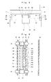
back side chute 50 is at a closed position, thebill conveying unit 40 is put into a state in which its front and back are sandwiched by thefront side chute 30 and theback side chute 50. Because of the existence of theupper curvature 31 and thecurvature 51 of theback side chute 50, an inverted-U shaped bill passage BP (see FIGS. 3, 5, and 9) is formed in the periphery of thebill conveying unit 40. The front side lower end of this bill passage BP is communicated with the back end of thebill insertion slot 61 through thecurvature 62 of themask 60. - As shown by an arrow mark in FIG. 5, in a state in which the bill is not yet inserted, the light from the
light emitting element 45 enters thecenter port 34a of thelight transmitting element 34 through the bill passage BP, and the incident light is separated by two firstlight reflecting portions 34c, and is transmitted by eachlight transmitting portion 34b, and each transmitted light is guided to the right and leftports 34a respectively by the right and left secondlight reflecting portions 34d, and each transmitted light is emitted from the right and leftports 34a, and enters the right and leftlight receiving elements 46 through the bill passage BP respectively. - When the bill PM such as a thousand-yen bill inserted into the
bill insertion slot 61 of themask 60, as shown in FIG. 9, reaches a layout line of theports 34a of thelight transmitting element 34, the light incidence on each light receivingelement 46 from the right and leftports 34a of thelight transmitting element 34 is blocked by the bill PM, and by the blocking of the light incidence on each light receivingelement 46, the insertion of the bill is detected. - After the detection of the bill insertion, both of the
endless belts 43 of thebill conveying unit 40 rotate counter-clock wise in FIG. 3, and by this rotation, the bill PM is pulled into the inverse U-shaped bill passage BP, and is conveyed to the detection areas of thebill validating sensors - The bill conveyed to the detection areas of the
bill validating sensors endless belts 43 of thebill conveying unit 40 rotate clock-wise in FIG. 3, and by this rotation, the bill is returned to thebill insertion slot 61 from the inverse U-shaped bill passage BP. - On the other hand, as a result of the authenticity check, in the case of a genuine bill, a signal relating to the genuine bill insertion is outputted through a control circuit (illustration omitted), and at the same time, both of the
endless belts 43 of thebill conveying unit 40 rotate counter-clock wise in FIG. 3, and by this rotation, the bill is conveyed to the back side of thebill storing plate 21 of thebase box 20. - The
bill storing plate 21 then presses thecassette plate 72 of thebill storing cassette 70 through the bill by resisting a spring biasing force, and both of the end edges in the width direction of the bill move backward up to a position climbing over both of therails 71 of thebill storing cassette 70, and after that, both of the end edges return to the front. By the operation of thisbill storing plate 21, the genuine bill is stored by being sandwiched between thecassette plate 72 of thebill storing cassette 70 and the tworails 71. - Next, referring mainly to FIGS. 4 and 8, the opening and closing operation of the
back side chute 50 in the bill validator will be described. - As shown in FIGS. 4 and 8, the
back side chute 50 located at the closed position is held at an appropriate position in a state in which thepins 57 of both the right and left sides are inserted into the lockingholes 35b of the locking strips 35 of both the right and left sides of thefront side chute 30. - When the
back side chute 50 located at the closed position is released on the occasion of performing the inspection, repairing, and the like of thebill conveying unit 40, thepressing portion 81 of the unlockinglever 80 is pressed downward by the finger and the like, thereby moving downward thebar portion 85 and both operatingportions 86. - Since the horizontal interval of the lower ends of both the operating
portions 86 of the unlockinglever 80 is slightly smaller than the horizontal interval of the inner surfaces of both lockingstrips 35, by the mutual contact by the downward movement of both operatingportions 86 accompanied with the pressing down, a force for driving out these lockingstrips 35 from eachinclined surface 86a is exerted, and each lockingstrip 35 is elastically deformed toward the outside, and each lockinghole 35b is simultaneously pulled out from eachpin 57, thereby the locking is released. - Hence, if the
back side chute 50 is rotated backward in an unlocking state with the support place as a point of support, thisback side chute 50 is released and thebill conveying unit 40 can be exposed, and if necessary, by pulling out thebill conveying unit 40 from the front-side chute 30, the desired inspection, repairing, and the like can be properly performed. - When the
back side chute 50 is to be restored to the closed position, theback side chute 50 may be rotated forward with the support place as a point of support. - Each locking
strip 35 can be elastically horizontally deformed, and since each back end inner side is provided with theinclined surface 35a, when theback side chute 50 is rotated forward with the support place as a point of support, the top end of eachpin 57 contacts theinclined surface 35a of each lockingstrip 35, and by this mutual contact, a force for driving out each lockingstrip 35 outside is exerted, and the each lockingstrip 35 is elastically deformed toward the outside. - When the
back side chute 50 reaches the closed position, as shown in FIGS. 4 and 8, eachpin 57 is again inserted and locked in thelocking hole 35b of each lockingstrip 35, so that theback side chute 50 is held at an appropriate closed position. - In this way, according to the above described bill validator, by arranging the
light transmitting element 34 capable of emitting the light incident on thecenter port 34a from the right and leftports 34a in the front surface side (front side chute 30) of the front and back surfaces opposed of the bill passage BP, thelight emitting element 45 and the receivingelement 46 can be arranged together at the back side (the unitmain body 41 of the bill conveying unit 40) of the front and back surfaces opposed of the bill passage BP, and therefore, the work of installing thelight emitting element 45 and thelight receiving elements 46 and the work of wiring can be simplified comparing to the previous works, and therefore the reduction in cost spent for these works can be realized. In addition, the number oflight emitting elements 45 can be reduced further than the number of light receivingelements 46, and even in this regard, a contribution can be made to reduce the cost. - Further, since three
ports 34a of thelight transmitting element 34 are linearly lined up orthogonally spaced apart in the direction to the bill insertion direction, when the inserted bill PM reaches the layout line of theports 34a of thelight transmitting element 34, the insertion of the bill PM can be accurately detected. - Further, the
light emitting element 45, thelight receiving element 46, and theboard 44 thereof are arranged in the unitmain body 41 of thebill conveying unit 40, and therefore, by releasing theback side chute 50 and pulling out thebill conveying unit 40 from thefront side chute 30, the inspection, repairing, and the like for thelight emitting element 45, thelight receiving element 46, and theboard 44 thereof can be simply performed. - Note that, in the above described bill validator, while an example has been shown by using one
light transmitting element 34, but as shown in FIGS. 10 and 11, when thelight transmitting element 34 and an approximately E-shapedlight transmitting element 36 smaller in width than the light transmittingelement 34 are superposed and used so that the light is allowed to enter thecenter ports light transmitting elements light emitting element 45, and a total of four pieces of thelight emitting element 46 are arranged by corresponding to the right and leftports light transmitting elements light transmitting elements - Further, in the above described bill validator, while the
center port 34a of thelight transmitting element 34 has been used for the light incidence and the right and leftports 34a have been used for the light emission, thecenter port 34a can be used for the light emission, and the right and leftports 34a can be used also for the light incidence. When thelight emitting element 45 is replaced by the light receiving element, and the right and leftlight receiving elements 46 are replaced by the light emitting element, the bill insertion detection similarly to the above can be performed. - It is to be understood that the above embodiments are illustrative and are not limited to the particulars disclosed. The scope of the invention is shown by the appended claims, and all the modified examples falling under the meaning of these claims are included in the present invention.
Claims (8)
- A bill validator including means for detecting an insertion of a bill (PM) into a bill passage (BP) ,
said means comprising:at least one light transmitting element (34) having a plurality of ports (34a) arranged at one of opposed surfaces of the bill passage (BP) and capable of emitting a light incident at least on one light incident port (34a) among the plurality of ports (34a) from at least one light emitting port (34a) among the plurality of ports (34a);at least one light emitting element (45) arranged at the other of the opposed surfaces of the bill passage (BP) and capable of allowing a light to enter the light incident port (34a) of the light transmitting element (34) through the bill passage (BP) ; andat least one light receiving element (46) arranged at the other of the opposed surfaces of the bill passage (BP) and capable of receiving the light emitted from the light emitting port (34a) of the light transmitting element (34) through the bill passage (BP). - The bill validator according to claim 1, wherein
the bill passage (BP) is formed between a bill conveying unit (40) having an endless belt (43) for conveying the bill (BP) and a front side chute (30) and a back side chute (50) sandwiching the bill conveying unit 40, and
the light transmitting element (34) is provided at the front side chute (30), and the light emitting element (45) and the light receiving element (46) are provided at the bill conveying unit (40) . - The bill validator according to claim 1 or 2, wherein
the plurality of ports (34a) of the light transmitting element (34) are linearly lined up spaced apart in a direction orthogonal to a insertion direction of the bill (BP). - The bill validator according to claim 3, wherein
the light transmitting element consists of one light transmitting element (34) having three ports (34a). - The bill validator according to claim 4, wherein
one port (34a) in the center among the three ports (34a) is used as the light incident port (34a), and the right and left two ports (34a) among the three ports (34a) are used as the light emitting port (34a) . - The bill validator according to claim 5, wherein
the light transmitting element (34) includes two light transmitting portions (34b) connecting the light incident port (34a) and each of the light emitting ports (34a) respectively, two first light reflecting portion (34c) for guiding the light incident on the light incident port (34a) to each of the light transmitting portions (34b) respectively, and two second light reflecting portions (34d) for guiding the light transmitted by each of the light transmitting portions (34b) to each of the light emitting ports (34a) respectively. - The bill validator according to claim 4, wherein
the right and left two ports (34a) among the three ports (34a) are used as the light incident port (34a), and one port (34a) in the center among the three ports (34a) is used as the light emitting port (34a) . - The bill validator according to claim 3, wherein
the light transmitting element is constituted by superposing two light transmitting elements (34 and 36) different in width and each having three ports (34a and 36a) .
Applications Claiming Priority (1)
| Application Number | Priority Date | Filing Date | Title |
|---|---|---|---|
| JP2006218742A JP2008046673A (en) | 2006-08-10 | 2006-08-10 | Paper money discrimination device |
Publications (2)
| Publication Number | Publication Date |
|---|---|
| EP1895481A2 true EP1895481A2 (en) | 2008-03-05 |
| EP1895481A3 EP1895481A3 (en) | 2008-12-17 |
Family
ID=38698433
Family Applications (1)
| Application Number | Title | Priority Date | Filing Date |
|---|---|---|---|
| EP07113730A Withdrawn EP1895481A3 (en) | 2006-08-10 | 2007-08-02 | Bill validator |
Country Status (2)
| Country | Link |
|---|---|
| EP (1) | EP1895481A3 (en) |
| JP (1) | JP2008046673A (en) |
Families Citing this family (3)
| Publication number | Priority date | Publication date | Assignee | Title |
|---|---|---|---|---|
| JP2016004389A (en) * | 2014-06-16 | 2016-01-12 | 株式会社日本コンラックス | Bill identification device |
| KR101799642B1 (en) * | 2015-10-02 | 2017-12-20 | 주식회사 엘지씨엔에스 | Financial device and Media detecting apparatus |
| KR101772767B1 (en) * | 2015-11-25 | 2017-08-29 | 주식회사 엘지씨엔에스 | Medium detecting apparatus and financial device |
Family Cites Families (7)
| Publication number | Priority date | Publication date | Assignee | Title |
|---|---|---|---|---|
| JP3849987B2 (en) * | 1994-12-26 | 2006-11-22 | サンデン株式会社 | Optical detector of paper sheet identification device |
| JPH0989538A (en) * | 1995-09-21 | 1997-04-04 | Oki Electric Ind Co Ltd | Optical sensor device |
| JP2001297349A (en) * | 2000-04-14 | 2001-10-26 | Sanden Corp | Paper money identifying device |
| CA2395726C (en) * | 2002-07-26 | 2011-01-11 | Cashcode Company Inc. | Banknote validator with improved drive path |
| CA2414424A1 (en) * | 2002-12-11 | 2004-06-11 | Cashcode Company Inc. | Metal bezel for validator |
| GB0319882D0 (en) * | 2003-08-23 | 2003-09-24 | Ncr Int Inc | A note skew detector |
| JP2007141109A (en) * | 2005-11-22 | 2007-06-07 | Mamiya Op Co Ltd | Paper sheet identification device |
-
2006
- 2006-08-10 JP JP2006218742A patent/JP2008046673A/en active Pending
-
2007
- 2007-08-02 EP EP07113730A patent/EP1895481A3/en not_active Withdrawn
Also Published As
| Publication number | Publication date |
|---|---|
| EP1895481A3 (en) | 2008-12-17 |
| JP2008046673A (en) | 2008-02-28 |
Similar Documents
| Publication | Publication Date | Title |
|---|---|---|
| EP0348140B1 (en) | Device for validating and accumulating bills and coins | |
| EP1460590A1 (en) | A banknote moving unit in a banknote storing unit | |
| CN1288604C (en) | Paper currency testing machine with improved drive pass | |
| EP1898367A1 (en) | Bill handling apparatus | |
| JP4222585B2 (en) | Paper sheet storage device | |
| US20080116034A1 (en) | Bill acceptor for money exchanging machine | |
| JP2004272815A (en) | State detection unit in banknote storage device | |
| US20080236989A1 (en) | Banknote Identification Apparatus | |
| JP4644474B2 (en) | Banknote handling equipment | |
| JP5456936B1 (en) | Paper sheet processing equipment | |
| JP2008046673A (en) | Paper money discrimination device | |
| JP5046702B2 (en) | Bill recognition device | |
| JP6265380B2 (en) | Paper sheet processing equipment | |
| CN105765635A (en) | Paper sheet processing device | |
| JPH0579679U (en) | Banknote handling device | |
| WO2000021042A1 (en) | Bank-note processing device | |
| EP2015258A2 (en) | Bill validator | |
| JP6344104B2 (en) | Game machine | |
| JP4916267B2 (en) | Bill recognition device | |
| KR100678679B1 (en) | Shutter device of automated equipment | |
| JP4222620B2 (en) | Paper sheet storage device | |
| JP4560343B2 (en) | Bill recognition device | |
| JPH0643770U (en) | Banknote handling device | |
| JP2567496Y2 (en) | Stacker for bills | |
| JP4959882B2 (en) | Bill storage device, bill transport device and pachinko machine |
Legal Events
| Date | Code | Title | Description |
|---|---|---|---|
| PUAI | Public reference made under article 153(3) epc to a published international application that has entered the european phase |
Free format text: ORIGINAL CODE: 0009012 |
|
| AK | Designated contracting states |
Kind code of ref document: A2 Designated state(s): AT BE BG CH CY CZ DE DK EE ES FI FR GB GR HU IE IS IT LI LT LU LV MC MT NL PL PT RO SE SI SK TR |
|
| AX | Request for extension of the european patent |
Extension state: AL BA HR MK YU |
|
| PUAL | Search report despatched |
Free format text: ORIGINAL CODE: 0009013 |
|
| AK | Designated contracting states |
Kind code of ref document: A3 Designated state(s): AT BE BG CH CY CZ DE DK EE ES FI FR GB GR HU IE IS IT LI LT LU LV MC MT NL PL PT RO SE SI SK TR |
|
| AX | Request for extension of the european patent |
Extension state: AL BA HR MK RS |
|
| 17P | Request for examination filed |
Effective date: 20090605 |
|
| 17Q | First examination report despatched |
Effective date: 20090710 |
|
| AKX | Designation fees paid |
Designated state(s): DE ES FR GB IT |
|
| STAA | Information on the status of an ep patent application or granted ep patent |
Free format text: STATUS: THE APPLICATION IS DEEMED TO BE WITHDRAWN |
|
| 18D | Application deemed to be withdrawn |
Effective date: 20091121 |