EP1895385A2 - Electronic apparatus and housing - Google Patents
Electronic apparatus and housing Download PDFInfo
- Publication number
- EP1895385A2 EP1895385A2 EP06127372A EP06127372A EP1895385A2 EP 1895385 A2 EP1895385 A2 EP 1895385A2 EP 06127372 A EP06127372 A EP 06127372A EP 06127372 A EP06127372 A EP 06127372A EP 1895385 A2 EP1895385 A2 EP 1895385A2
- Authority
- EP
- European Patent Office
- Prior art keywords
- unit
- opening
- side connector
- disc drive
- drive unit
- Prior art date
- Legal status (The legal status is an assumption and is not a legal conclusion. Google has not performed a legal analysis and makes no representation as to the accuracy of the status listed.)
- Withdrawn
Links
Images





















Classifications
-
- G—PHYSICS
- G06—COMPUTING OR CALCULATING; COUNTING
- G06F—ELECTRIC DIGITAL DATA PROCESSING
- G06F1/00—Details not covered by groups G06F3/00 - G06F13/00 and G06F21/00
- G06F1/16—Constructional details or arrangements
- G06F1/18—Packaging or power distribution
- G06F1/183—Internal mounting support structures, e.g. for supporting printed circuit boards
- G06F1/187—Mounting of fixed or removable disk drives
-
- G—PHYSICS
- G09—EDUCATION; CRYPTOGRAPHY; DISPLAY; ADVERTISING; SEALS
- G09B—EDUCATIONAL OR DEMONSTRATION APPLIANCES; APPLIANCES FOR TEACHING, OR COMMUNICATING WITH, THE BLIND, DEAF OR MUTE; MODELS; PLANETARIA; GLOBES; MAPS; DIAGRAMS
- G09B23/00—Models for scientific, medical, or mathematical purposes, e.g. full-sized devices for demonstration purposes
- G09B23/06—Models for scientific, medical, or mathematical purposes, e.g. full-sized devices for demonstration purposes for physics
- G09B23/18—Models for scientific, medical, or mathematical purposes, e.g. full-sized devices for demonstration purposes for physics for electricity or magnetism
- G09B23/183—Models for scientific, medical, or mathematical purposes, e.g. full-sized devices for demonstration purposes for physics for electricity or magnetism for circuits
-
- G—PHYSICS
- G06—COMPUTING OR CALCULATING; COUNTING
- G06F—ELECTRIC DIGITAL DATA PROCESSING
- G06F1/00—Details not covered by groups G06F3/00 - G06F13/00 and G06F21/00
- G06F1/16—Constructional details or arrangements
- G06F1/1613—Constructional details or arrangements for portable computers
- G06F1/1615—Constructional details or arrangements for portable computers with several enclosures having relative motions, each enclosure supporting at least one I/O or computing function
- G06F1/1616—Constructional details or arrangements for portable computers with several enclosures having relative motions, each enclosure supporting at least one I/O or computing function with folding flat displays, e.g. laptop computers or notebooks having a clamshell configuration, with body parts pivoting to an open position around an axis parallel to the plane they define in closed position
-
- G—PHYSICS
- G06—COMPUTING OR CALCULATING; COUNTING
- G06F—ELECTRIC DIGITAL DATA PROCESSING
- G06F1/00—Details not covered by groups G06F3/00 - G06F13/00 and G06F21/00
- G06F1/16—Constructional details or arrangements
- G06F1/1613—Constructional details or arrangements for portable computers
- G06F1/1633—Constructional details or arrangements of portable computers not specific to the type of enclosures covered by groups G06F1/1615 - G06F1/1626
- G06F1/1656—Details related to functional adaptations of the enclosure, e.g. to provide protection against EMI, shock, water, or to host detachable peripherals like a mouse or removable expansions units like PCMCIA cards, or to provide access to internal components for maintenance or to removable storage supports like CDs or DVDs, or to mechanically mount accessories
-
- G—PHYSICS
- G06—COMPUTING OR CALCULATING; COUNTING
- G06F—ELECTRIC DIGITAL DATA PROCESSING
- G06F1/00—Details not covered by groups G06F3/00 - G06F13/00 and G06F21/00
- G06F1/16—Constructional details or arrangements
- G06F1/1613—Constructional details or arrangements for portable computers
- G06F1/1633—Constructional details or arrangements of portable computers not specific to the type of enclosures covered by groups G06F1/1615 - G06F1/1626
- G06F1/1656—Details related to functional adaptations of the enclosure, e.g. to provide protection against EMI, shock, water, or to host detachable peripherals like a mouse or removable expansions units like PCMCIA cards, or to provide access to internal components for maintenance or to removable storage supports like CDs or DVDs, or to mechanically mount accessories
- G06F1/1658—Details related to functional adaptations of the enclosure, e.g. to provide protection against EMI, shock, water, or to host detachable peripherals like a mouse or removable expansions units like PCMCIA cards, or to provide access to internal components for maintenance or to removable storage supports like CDs or DVDs, or to mechanically mount accessories related to the mounting of internal components, e.g. disc drive or any other functional module
-
- G—PHYSICS
- G09—EDUCATION; CRYPTOGRAPHY; DISPLAY; ADVERTISING; SEALS
- G09B—EDUCATIONAL OR DEMONSTRATION APPLIANCES; APPLIANCES FOR TEACHING, OR COMMUNICATING WITH, THE BLIND, DEAF OR MUTE; MODELS; PLANETARIA; GLOBES; MAPS; DIAGRAMS
- G09B19/00—Teaching not covered by other main groups of this subclass
- G09B19/0053—Computers, e.g. programming
-
- G—PHYSICS
- G09—EDUCATION; CRYPTOGRAPHY; DISPLAY; ADVERTISING; SEALS
- G09B—EDUCATIONAL OR DEMONSTRATION APPLIANCES; APPLIANCES FOR TEACHING, OR COMMUNICATING WITH, THE BLIND, DEAF OR MUTE; MODELS; PLANETARIA; GLOBES; MAPS; DIAGRAMS
- G09B23/00—Models for scientific, medical, or mathematical purposes, e.g. full-sized devices for demonstration purposes
- G09B23/06—Models for scientific, medical, or mathematical purposes, e.g. full-sized devices for demonstration purposes for physics
- G09B23/18—Models for scientific, medical, or mathematical purposes, e.g. full-sized devices for demonstration purposes for physics for electricity or magnetism
- G09B23/187—Models for scientific, medical, or mathematical purposes, e.g. full-sized devices for demonstration purposes for physics for electricity or magnetism for measuring instruments
Definitions
- the present invention relates to an electronic apparatus that is provided with a unit such as a hard disc unit.
- a data processing apparatus such as a notebook personal computer (hereafter referred to as "note PC”) has a built-in hard disc unit that houses a hard disc therein.
- a typical note PC is configured such that an opening for housing a hard disc unit is formed in the bottom face thereof to allow detachable housing of the hard disk unit and a connector of the hard disc unit(hereafter referred to as “a unit side connector”) is connected with a connector of the note PC (hereafter referred to as "an apparatus side connector).
- a hard disc In order to obtain correct connection between the unit side connector and the apparatus side connector, a hard disc should be placed horizontally in the opening for the hard disc unit and then pushed to slide along the opening.
- Japanese Patent Application Publication No. 2002-93501 discloses that an opening for receiving connector pins of the hard disk unit is also formed in the top surface, in addition to the side surface, of the connector of the apparatus side, thereby reducing the size of the opening for loading the hard disc unit. Although this technique achieves the reduction in size of the opening for the hard disk unit, it does not eliminate the possibility of insert the hard disc unit obliquely.
- Japanese Patent Application Publication No.200 - 4839 discloses that a projection formed on the front end of the connector of the hard disk unit, abuts the connector of the apparatus when the hard disk unit is to be obliquely inserted, thereby preventing wrong connection between the connectors.
- This technique prevents wrong connection of the connectors when the hard disk unit is inserted obliquely, thereby preventing the damage of the connector.
- connector pins of the hard disk unit are usually aligned in two rows which are received by the corresponding insertion holes aligned in two rows. Accordingly, the technique disclosed in Japanese Patent Application Publication No.2001-14839 does not prevent wrong connection of the connectors in a case where connector pins aligned in the lower row are inserted in the insertion holes in the upper row of the apparatus side-connector.
- Japanese Patent Application Publication No.2002-297263 discloses space-saving structure in which a case housing multiple hard disc devices is adapted to be pulled, but does not relate to prevention of wrong connection of connectors.
- the present invention has been made in view of the above circumstances, and provides an electronic apparatus having a unit is housed in an opening of the apparatus and whose connector is to be connected to a connector of the apparatus, and prevents wrong connection and damage of the connectors.
- An electronic apparatus having:
- the expression of "at least an end of the unit, which is positioned opposite the unit side connector, is lifted” includes both states that the unit is lifted obliquely and that the unit is lifted in a horizontal posture.
- the projection is formed at each of both side walls of the opening.
- the unit has a metal frame with an interfering section that interferes with the projection when the unit is pressed against the apparatus side connector while at least a front end of the unit is lifted.
- the interfering section corresponding to the projection may be provided in the metal frame while the body of the unit is not modified. This suppresses increase in the number of modifications with respect to the conventional apparatus.
- the unit side connector may have plural connection pins aligned in upper and lower rows, and the apparatus side connector may have plural insertion holes aligned in upper and lower rows in which the connection pins aligned in the upper and lower rows are inserted respectively. Further, the unit may have a built-in hard disc and accesses the hard disc.
- the invention can be applied to, for example, a note PC that includes:
- the electronic apparatus according to the invention can prevent wrong connection and damage of the connectors.
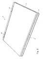
- Fig. 1 is a perspective view of a notebook computer 10 (hereafter referred to as a notebook PC) when closed
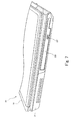
- Fig. 2 is a perspective view of the notebook PC 10 when closed, as viewed obliquely from its front
- Fig. 3 is a perspective view of the notebook PC 10 when closed, as viewed obliquely from its back.
- the notebook PC 10 is composed of a main unit 20 and a display unit 30.
- the display unit 30 is connected via a hinge mechanism 40 with the main unit 20 at the back of the main unit 20 so as to be openable and closable.
- the main unit 20 has various components incorporated in the housing thereof, including circuits such as CPU, a hard disc drive unit to access a CD and a DVD loaded therein, a PC card slot to access a PC card inserted therein, a memory card slot to access various kinds of memory cards inserted therein and so on.
- circuits such as CPU, a hard disc drive unit to access a CD and a DVD loaded therein, a PC card slot to access a PC card inserted therein, a memory card slot to access various kinds of memory cards inserted therein and so on.
- a keyboard 21 On the top face of the main unit 20, disposed are a keyboard 21, a touchpad 22, right and left push buttons 22b and 22a, a fingerprint sensor 23 disposed between the push buttons 22b and 22a, a power button 24 disposed at the right back, plural indicator lamps 25 and plural function buttons 26 disposed at the left back.
- a locking aperture 27 is disposed on the top face of the main unit 20 .
- the locking aperture 27 receives a locking claw 31 of the display unit 30, when the display unit 30 is closed to be overlaid over the main unit 20, and the display unit 30 locks into the main unit 20 such that the display unit 30 does not easily open.
- an unlocking button 32 of the display unit 30 is to be pressed to unlock the locking claw 31 and the display unit 30 is to be lifted with a hand.
- a long and narrow cover member 28 extending laterally is disposed at the back of the keyboard 21 on the top face of the main unit 20, which be described later in detail.
- the display unit 30 has, in addition to the locking claw 31 and the unlocking button 32, a display screen 33 disposed at the inside thereof and facing the main unit 20 when closed. Various images are displayed on the display screen 33 in response to instructions from the CPU of the main unit 20.
- the hinge mechanism 40 supports the display unit 30 such that the display unit 30 can open and close relative to the main unit 20 and can be kept opening at any degree by friction of the hinge mechanism 40.
- Fig. 4 shows a front face of the notebook PC 10 shown in Figs. 1 through 3 when closed.
- audio output ports 201a, 201b are disposed respectively at the left and right thereof to output sound from a built-in microphone to outside the apparatus. Further, disposed are a microphone connection port 202 for connecting a microphone jack thereto, a headphone connection port 203 for connecting a headphone jack thereto, and an On/Off switch 204 for turning on/off wireless LAN function.
- Fig. 5 shows a back face of the notebook PC 10 shown in Figs. 1 through 3 when closed.
- a modem circuit connecting port 205 On the flank of the back of the main unit 20, disposed in the order from the right to the left are a modem circuit connecting port 205, an external monitor connecting connector 206, air outlets 207 from which air blown from a fan inside the main unit 20 is discharged, a video output terminal 208, a LAN connection terminal 209, two USB connection terminals 210a, 210b and a locking aperture 211 for connecting a theft-proof wire thereto.
- heat radiating fins 241 a heat radiating member 240 are exposed to be seen at the back of the air outlets 207.
- Fig. 6 shows a right flank of the notebook PC 10 shown in Figs. 1 through 3 when closed.
- an AC adopter (not shown) power cable connecting port 212, an IEEE 1394 connecting terminal 213, a USB connecting terminal 214, a media loading opening 215 in which plural types of storage media, tour in the embodiment, can be inserted, and a PC card loading opening 216 in which plural PC cards are to be inserted.
- an AC adopter not shown
- the main unit 20 upper and lower PC card slots capable of accommodating two PC cards and having corresponding upper and lower cover members 217 and 218 are disposed inside the PC card loading opening 216.
- the cover members 217 and 218 are pressed by a spring from inside the housing of the main unit 20 so as to be closed, as shown in Fig. 6.
- the notebook PC card loading opening 216 is adopted to be opened in the following manner: when a PC card is inserted into the upper PC slot, the upper cover member 217 is pressed by the front end of the PC card and rotated such that the upper cover member 217 is lifted up around a top edge 217a thereof; on the other hand, when a PC card is inserted into the lower PC slot, the lower cover member 218 is pressed by the front end of the PC card and rotated such that the lower cover member 218 goes down around a bottom edge 218a thereof.
- an eject button 219 disposed next to the PC card loading opening 216 is to be pressed.
- Fig. 7 shows a left flank of the notebook PC 10 shown in Figs. 1 through 3 when closed.
- a disc drive unit 220 On the flank of the left of the main unit 20, arranged is an end face of a disc drive unit 220 to access a CD and a DVD loaded therein. Pressing an eject button 221 causes a tray to pop out from inside the housing of the main unit 20. Placing CD and DVD on the tray and pushing it enables the CD and DVD to be accessed by the disc drive unit 220. When removing the CD and DVD, the eject button 221 is to be pressed similarly.
- an opening of the same shape as that of the end face of the disc drive unit 220 is formed in the housing of the main unit 20.
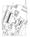
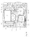
- Fig. 8 shows a top face of the notebook PC 10 shown in Figs. 1 through 3 with its cover member removed therefrom.
- Fig. 9 is an enlarged view of a portion at the back of a keyboard 21 on the top face of the main unit 20 of the notebook PC 10.
- An elongated cover member 28, as shown in Fig. 1, is disposed at the back of the keyboard 21 on the top face of the main unit 20. Opening the cover member 28 exposes an opening 231 formed inside the housing of the main unit 20.
- An air inlet portion 241a of the heat radiating fins 241 of the heat radiating member 240 can be seen through the opening 231.
- the heat radiating member 240 will be described later in detail.
- the air inlet portion 241a is likely to be covered in dust because air from the fan 250 blows against it. The accumulated dust in the air inlet portion 241a prevents air flow from the fan 250, downgrading coolability, leading to rise in temperature inside the housing of the main unit 20 and thus possibly resulting in malfunction and failure of the notebook PC 10.
- the notebook PC 10 has such a configuration that the air inlet portion 241a can be exposed by taking off the cover member 28 to enable easy removal of dust accumulated therein.
- the positioning claws 281 and 282 engage in positioning holes 232 and 233 formed in the housing of the main unit 20 while the locking claws 283, 284 and 285 respectively engage in locking holes 234, 235 and 236 formed in the housing of the main unit 20, so that the cover member 28 is attached to the housing of the main body so as to close the opening 231.
- a recess 237 with space for a finger or a nail to be placed therein is formed in the housing of the main unit 20 in order to enable easy taking off of the cover member 28 attached to the housing.
- the cover member 28 can be easily taken off by placing a finger or a fingernail under the recess 237 and lifting up the cover member 28.
- Fig. 10 illustrates a fan and a portion of the heat radiating member 240 with a top cover and the keyboard 21 of the main unit 20 removed therefrom.
- Fig. 11 illustrates the portion of the heat radiating member 240 as viewed at different angle from that in Fig. 10.
- a main circuit board 251 mounted with various circuit components is arranged around the fan 250.
- a metal plate 252 with several holes formed therein is arranged above the fan 250, the main circuit board 251, and the heat radiating member 240.
- a top face of the heat radiating member 240 stands higher than that of the fan 250, so that a shield portion 252a formed in the metal plate 252 for covering the top face of the heat radiating member 240 is raised from the level of the rest of the metal plate 252.
- the metal plate 252 serves as an electromagnetic shield as well as a base for the keyboard 21 (see Fig. 1) that is arranged on the metal plate 252.
- Fig. 12 shows a positional relationship between the fan 250 and the heat radiating member 240 with the metal plate 252 removed therefrom.
- the heat radiating member 240 serves for radiating heat generated by the two LSIs, which will be described later in detail.
- Air blown from the fan 250 enters the air inlet portion 241a to reach the heat radiating fins 241 and then is warmed up while passing between the heat radiating fins 241 by absorbing heat therefrom and exits from the air outlets 207 (also see Fig. 5) formed in the flank of the back of the main unit 20.
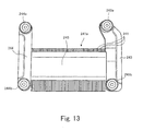
- the heat radiating member 240 includes a flat base section (hereafter referred to as “a base plate”) 242, the multiple pieces of radiating fins 241 that are fixed to and stand on the base plate 242 and a pair of arms (hereafter referred to as “arm plates”) 243, 244 that extend horizontally at both ends of the base plate 242.
- the arm plates 243, 244 include fasteners 243a, 243b, and 244a, 244b respectively disposed at the front and the back thereof for fastening the heat radiating member 240 with screws.
- the heat radiating member 240 has a fixed section (hereafter referred to as "a fixed plate") 245 that stands at both ends of the heat radiating fins 241 and links the both ends by extending over the heat radiating fins 241 like a bridge.
- the pair of arm plates 243, 244 are formed by extending the fixed plate 245.
- the manufacturing process of the heat radiating member 240 is as follows: solder is applied to the bottom of each of the heat radiating fins 241 to place them on the top face of the base plate 242; then, solder is applied to the top of each of the heat radiating fins 241 to attach the heat radiating fins 241 and the base plate 242 to the fixed plate 245, which are subjected to solder-joint with a furnace to complete manufacturing.
- the fasteners 243a, 234b, and 244a, 244b respectively have a structure of a fixed pedestal with a spring incorporated therein.
- the heat radiating member 240 is pressed against heat radiating components by means of springs when fastened with screws.
- Such a structure is well known art and thus further explanation is omitted.
- Fig. 15 shows heat generating components on the main circuit board 251.
- Fig. 15 illustrates CPU 253a and chipset 254a disposed near the CPU 253a that are heat generating components to be cooled by the heat radiating member 240 shown in Fig. 14.
- the CPU 253a generates larger amount of heat than the chipset 254a, it is placed so as to be efficiently cooled by the heat radiating member 240.
- the CPU 253a is disposed under the base plate 242, so that heat generated by the CPU 253a is conducted via the base plate 242 to the heat radiating fins 241 from the bottom thereof.
- the chipset 254a is disposed under one of arm plates 243, 244 (in this case the arm plate 243), so that heat generated by the chipset 254a is conducted via the fixed plate 245 to the heat radiating fins 241 from the top thereof.
- Fig. 16 illustrates two heat generating components, that is, the CPU 253a and the chipset 254a, and a bottom face of the heat radiating member 240 that contacts the heat generating components.
- the heat radiating member 240 is arranged on the CPU 253a and the chipset 254a so as to be in contact with them via thermal 1 grease.
- the heat radiating member 240 is attached to the CPU 253a and the chipset 254a by screwing the fasteners 243a, 243b and 244a, 244b of the arm plates 243, 244 in the four respective holes 251a, 5 band 251c, 251d formed in the main circuit board 251, a substantial center "a" of the CPU 253a contacts a substantial center "a'” of the base plate 242 of the heat radiating member 240, while a substantial center "b” of the chipset 254a contacts a substantial center "b'” having a downward projection of the arm plate 243.
- the downward projection of the arm plate 243 will be described later in detail.
- Fig. 17 show positional relation between a CPU and a chipset different from that shown in Figs. 15 and 16
- the notebook PC 10 includes two kinds of notebook PCs mounted with two kinds of CPUs and chipsets of different manufacturers.
- Figs. 15 and 16 show positional relation between CPU 253b and chipset 254b of a first kind of the notebook PCs while Fig. 17 shows that of a second kind of the notebook PC.
- Fig. 18 illustrates two heat generating components, that is, the CPU 253b and the chipset 254b, and a bottom face of the heat radiating member that contacts the heat generating components.
- the heat radiating member 240 is arranged on the CPU 253b and the chipset 254b so as to be in contact with them via thermal grease.
- the heat radiating member 240 is attached to the CPU 253b and the chipset 254b by screwing the fasteners 243a, 243b and 244a, 244b of the arm plates 243, 244 in the four respective holes 251a, 251b and 251c, 251d formed in the main circuit board 251, a substantial center "c" of the CPU 253b contacts a substantial center "c'" of the base plate 242 of the heat radiating member 240, while a substantial center “d” of the chipset 254b contacts a substantial center "c" of the arm plate 244.
- the heat radiating member 240 has such a structure that difference in height between the CPU 253a and 253b is offset by the amount of contraction and extension of the springs of the fasteners 243a, 243b and 244a, 244b, while difference in height between the chipsets 254a and 254b is offset by the shape of the arm plate 243.
- Such a structure enables the heat radiating member 240 of the same shape to be used for the two kinds of notebook PCs, by aligning the holes 251a, 251b and 251c, 251d formed in the main circuit board 251 of the notebook PC 10 with the fasteners 243a, 243b and 244a, 244b of the arm plates 243, 244 of the heat radiating member 240.
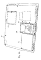
- Fig. 19 is a perspective view of a bottom face of the main unit 20 of the notebook PC 10.
- Fig. 19 shows a cover member 261 for closing the hard disc drive unit loading opening, a cover member 262 for closing a battery loading opening and a cover member 263 for closing a memory card loading opening.
- Fig. 20 shows the bottom face of the main unit 20 of the notebook PC shown in Fig. 19, with the cover member 261 for closing the hard disc drive unit loading opening removed therefrom.
- an opening 265 for housing a hard disc drive unit 270 is formed in the bottom face of the main unit 20 and the hard disc drive unit 270 is housed therein.
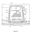
- Fig. 21 is an enlarged view of the opening 265 and the hard disc drive unit 270 housed therein.
- two screws 264a and 264b are first to be disengaged to pull a sheet 271 in the direction indicated by the arrow A, thereby disengaging a unit side connector 273 (see Fig. 22), which will be described later. Then, the hard disc drive unit 270 is ready to be removed from the opening 275.
- the hard disc drive unit 270 is first to be placed on a position little displaced from the position indicated by Fig. 21 toward the direction indicated by the arrow A.
- the opening 265 has a pair of projections 266a and 266b projecting inside and disposed at both sides thereof.
- the projections 266a and 266b interfere with the hard disc drive unit 270, if the unit side connector 273 is to be engaged while the back end (opposite the unit side connector 273) of the hard disc drive unit 270 is lifted obliquely or the whole of the hard disc drive unit 270 is lifted from the level of the opening 265.
- the projections 266a and 266b prevent wrong connection of the unit side connector 273 and failures such as bent back connector pins.
- the opening 265 has projections 267a, 267b, and 268a, 268b disposed at both sides thereof that serve for engaging the cover member 261 (see Figs. 19 and 31) for the opening 265.
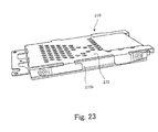
- Figs. 22 through 24 illustrate the hard disc drive unit 270 as viewed from different angles from that in Fig. 21.
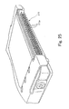
- Fig. 25 is a perspective view of the unit side connector 273 provided in the hard disc drive unit 270.
- the hard disc drive unit 270 is provided with a metal frame 272 that is fastened to the hard disc drive unit 270 with screws in the side portions thereof that are formed by extending the metal frame 272 and bending it at the both edges.
- the metal frame 272 serves for maintaining strength of the hard disc drive unit 270 as well as shielding electromagnetic force of its internal hard disc and magnetic disc. Multiple holes formed in the metal frame 272 are intended for reduction in weight while maintaining strength and shielding performance.
- the metal frame 272 also serves for preventing wrong engagement of the unit side connector 273.
- interfering sections 272a and 272b of the metal frame 272 interfere with the projections 266a and 266b of the opening 265.
- the hard disc drive unit 270 is provided with the unit side connector 273 at the front end thereof. As shown in Fig. 25, the unit side connector 273 has multiple connection pins 273a aligned in two rows.
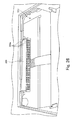
- Fig. 26 shows an apparatus side connector 269 that is to be connected with the unit side connector 273 provided in the hard disc drive unit 270.
- the apparatus side connector 269 has multiple pin insertion holes 269a aligned in two rows to receive the corresponding connection pins 273a aligned in two rows of the unit side connector 273 provided in the hard disc drive unit 270.
- Fig. 27 is a perspective view of one side of the opening 265 in which the hard disc drive unit 270 is housed.
- the side of the opening 265 is configured such that the metal frame 272 (see Fig. 22) goes under the projection 266a disposed at the side of the opening 265 when the hard disc drive 270 is housed in the opening 265. The same holds true for the projection 266b at the other side of the opening 265.
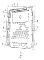
- Figs. 8 and 29 show the state in which the hard disc drive 270 is about to be housed in the correct position in the opening 265.
- the hard disc drive unit 270 is placed in the position indicated in Figs. 28 and 29, and pressed in the direction indicated by the arrow B, thereby making the unit side connector 273 to be engaged with the apparatus side connector 269. As the hard disc drive unit 270 is placed in the correct position, the interfering sections 272a, 272b of the metal frame 272 of the hard disc drive unit 270 do not interfere with the projections 266a and 266b provided in the opening 265, so that the hard disc drive unit 270 goes under the 266a and 266b.
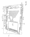
- Fig. 30 shows the state in which the hard disc drive unit 270 with its back obliquely lifted is placed in the opening 265.
- Fig. 30 shows the case in which the rack of the hard disc drive unit 270 is obliquely lifted. However, the same holds true for the case in which the whole of the hard disc drive unit 270 is lifted from the opening 265 in a horizontal posture. Further, there may be a case in which the connection pins 273a aligned in the lower row of the unit side connector 273 are inserted in the insertion holes 269a aligned in the upper row of the apparatus side connector 269. In such a case, however, the interfering section 272a, 272b are to be positioned over the projections 266a, 266b, and thus the hard disc drive unit 270 cannot be housed in the opening 265 nor the cover member 261 (see Fig.
- the interfering section 272a, 272b are to be positioned over the projections 266a, 266b, and thus the hard disc drive unit 270 cannot be housed in the opening 265 nor the cover member 261 (see Fig. 19) for closing the opening 265 can be attached. Accordingly, it is easy to grasp that the hard disc drive unit 270 is not properly housed in the opening 265.
- the interfering section 272a, 272b are positioned under the projections 266a, 266b. Accordingly, when the hard disc drive unit 270 is removed from the opening 265, it is not possible to lift the back of the hard disc drive unit 270 before releasing the engagement between the connectors 269 and 273. Thus, it is possible to secure that the unit side connector 273 is properly pulled from the apparatus side connector 269.
- Fig . 31 shows a back face of the cover member 261 for closing the opening 265 in which the hard disc drive unit 270 is housed.
- the cover member 261 On the back face of the cover member 261, disposed are two projections 301a, 301b projecting toward the depth of the opening 265 (see Fig. 21), two projecting claws 302a and 302b engaging the two projections 267a and 267b that are disposed at both sides of the opening 265 and projecting inside thereof, and two engaging claws 303a, 303b engaging the two projections 268a, 268b that project from the back end of the opening 265. Additionally, the cover member 261 has a hole 304 formed at the back side thereof. The cover member 261 closes the opening 265, as shown in Fig.
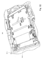
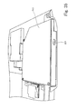
- Fig. 32 is a perspective view of the PC card slot 280
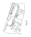
- Fig. 33 is a perspective view of the PC card slot 280 shown in Fig. 32, with the lower cover member shown in Fig. 6 opened.
- the PC card slot 280 is disposed in the housing of the notebook PC 10 inside the PC card loading opening 216 (see Fig. 6) formed in the flank of the right side of the notebook PC 10, such that it faces the PC card loading opening 216.
- the PC card slot 280 is consisted of a metal frame and configured to accommodate two PC cards vertically which are inserted in the PC card loading opening 216.
- a circuit board mounted with circuits for accessing a PC card inserted in the PC card slot 280 is provided under the PC card slot 280.
- the PC card loading opening 216 is configured such that the upper and lower cover members 217 and 218 are openably closed.
- a PC card is received by the PC card loading opening 216 as follows: when a PC card is inserted into the PC card loading opening 216, the upper cover member 217 is pressed by the front end of the PC card and rotated such that the upper cover member 217 is lifted up around the top edge 217a thereof; when the lower cover member 218 is pressed by the front end of the PC card, the lower cover member 218 is rotated such that the lower cover member 218 goes down around the bottom edge 218a thereof.
- Fig. 33 shows the state that the lower cover member 218 of the two cover members for closing the PC card loading opening 216 is opened.
- the opened cover member 218 covers the front end 2801a of the insulation sheet 2801, which prevents the PC card inserted in the PC card loading opening 216 from abutting the front end 2801a of the insulation sheet 2801 and thus the insulation sheet 2801 from being turned up.
- Fig. 34 compares the PC card slot (A) according to the embodiment of the notebook PC of the invention with a typical example of the conventional PC card slot (B).
- the front end of the insulation sheet 2801 is adhered onto a circuit board thereunder by using a double side tape.
- the front end of the circuit board is flush with the front end 2801a of the insulation sheet 2801.
- the front end of the PC card abuts the front end 2801a of the insulation sheet 2801.
- Frequent occurrence of such abutting causes the front end 2801a of the insulation sheet 2801 to be turned up and thereby damaging the circuit board the front end of the PC card, leading to malfunction of the apparatus.
- the circuit board is shorter relative to the typical conventional PC card slot (B), as indicated by dotted lines in Fig. 34 (A), and the insulation sheet 2801 is extended closer to the PC card loading opening 216 (see Fig. 6). Accordingly, as shown in Fig. 32, the front end 2801a of the insulation sheet 2801 is covered by the downwardly opened cover member 218, which prevents the insulation sheet 2801 from being turned up and thereby prevents damage of the circuit board. Additionally, the need to adhere the insulation sheet 2801 onto the circuit board is eliminated, resulting in decrease in the number of assembly works.
- Fig. 35 is a perspective view of the disc drive unit 220 with the top cover of the housing of the main unit 20 of the notebook PC 10 removed therefrom.
- the disc drive unit 220 as shown in Fig. 7, is inserted from the opening formed in the left-side flank of the housing of the main unit 20 to be housed therein.
- Fig. 36 shows a disc drive unit accommodating section to accommodate the disc drive unit 220
- Fig. 37 shows one side-end of the disc drive unit accommodating section 310
- Fig. 38 shows the other side-end thereof.
- the main circuit board 251 (see Fig. 38) and a sub circuit board 320 (see Fig. 36) are disposed at the both sides of the disc drive unit accommodating section 310.
- a flat cable 321 for electrically connecting the main circuit board 251 and the sub circuit board 320 is laid across the disc drive unit accommodating section 310.
- the flat cable 321 may be a flexible wiring board.
- the flat cable 321 is arranged under the disc drive unit 220 after the disc drive unit 220 is accommodated in the disc drive unit accommodating section 310.
- the disc drive unit 220 inserted into the disc drive unit accommodating section 310 may be caught on the flat cable 321, leading to failures such as disconnection.
- a sheet 322 is provided such that the flat cable 321 is wrapped by the sheet 322 folded back at a position close to the opening for the disc drive unit 220.
- the sheet 322 is adhered to a face of the disc drive unit accommodating section 310 at a position away from the opening for the disc drive unit 220 by using an adhesive tape 323.
- Fig. 39 shows a sheet to be spread under the sub circuit board 320, with the sub circuit board 320 and the flat cable 321 removed therefrom.
- An insulation sheet 324 is spread under the sub circuit board 320 for insulating electrical connection between the sub circuit board 320 and the housing of the main unit 20. It should be noted that the sheet 322, which wraps the flat cable 321 as shown in Figs. 36 and 37, is formed by extending the insulation sheet 324. This suppresses increase the number of the components.
- Fig. 40 shows an insulation sheet that is spread under the main and sub circuit boards 251, 320, with the circuit boards 251, 320 removed therefrom.
- An insulation sheet 325 is laid under the main circuit board 251.
- the disc drive unit 220 inserted into the disc drive unit accommodating section 310 is caught on the flat cable 321, by using the insulation sheet 324 for the sub circuit board 320 to wrap the flat cable 321 running across the disc drive unit accommodating section 310.
Landscapes
- Engineering & Computer Science (AREA)
- Computer Hardware Design (AREA)
- Theoretical Computer Science (AREA)
- Physics & Mathematics (AREA)
- General Physics & Mathematics (AREA)
- General Engineering & Computer Science (AREA)
- Human Computer Interaction (AREA)
- Business, Economics & Management (AREA)
- Mathematical Physics (AREA)
- Educational Technology (AREA)
- Educational Administration (AREA)
- Mathematical Analysis (AREA)
- Mathematical Optimization (AREA)
- Pure & Applied Mathematics (AREA)
- Computational Mathematics (AREA)
- Algebra (AREA)
- Power Engineering (AREA)
- Entrepreneurship & Innovation (AREA)
- Casings For Electric Apparatus (AREA)
- Coupling Device And Connection With Printed Circuit (AREA)
- Details Of Connecting Devices For Male And Female Coupling (AREA)
- Cooling Or The Like Of Electrical Apparatus (AREA)
Abstract
Description
- The present invention relates to an electronic apparatus that is provided with a unit such as a hard disc unit.
- Conventionally, a data processing apparatus such as a notebook personal computer (hereafter referred to as "note PC") has a built-in hard disc unit that houses a hard disc therein. As accessing the hard disc housed in a hard disc unit is accompanied by mechanical movement, a hard disc unit is vulnerable to a failure. Therefore, a typical note PC is configured such that an opening for housing a hard disc unit is formed in the bottom face thereof to allow detachable housing of the hard disk unit and a connector of the hard disc unit(hereafter referred to as "a unit side connector") is connected with a connector of the note PC (hereafter referred to as "an apparatus side connector).
- In order to obtain correct connection between the unit side connector and the apparatus side connector, a hard disc should be placed horizontally in the opening for the hard disc unit and then pushed to slide along the opening.
- However, due to the demand for miniaturization of a note PC as a whole, an opening for loading a hard disk unit is also limited in space. Such a situation entails a problem that a disc unit is inserted obliquely to cause damage the connector, or wrong connection of the connectors is unnoticed to cause malfunction of the note PC.
- In order to deal with such a problem,
Japanese Patent Application Publication No. 2002-93501 - On the other hand,
Japanese Patent Application Publication No.200 - 4839 Japanese Patent Application Publication No.2001-14839 - Additionally,
Japanese Patent Application Publication No.2002-297263 - The present invention has been made in view of the above circumstances, and provides an electronic apparatus having a unit is housed in an opening of the apparatus and whose connector is to be connected to a connector of the apparatus, and prevents wrong connection and damage of the connectors.
- An electronic apparatus according to the invention having:
- a housing including an opening formed therein for accommodating a unit that has a unit side connector;
- an apparatus side connector that is disposed at the back of the opening so as to be seen through the opening, and is to be connected with the unit side connector; and
- a projection that prevents wrong operation, the projection protruding from a sidewall of the opening toward inside the opening, the projection evading interference with the unit when the unit is placed in the opening in a normal posture and inserted in the apparatus side connector, the projection interfering with the unit when the unit is pressed toward the apparatus side connector, while at least an end of the unit, which is positioned opposite the unit side connector, is lifted.
- Incidentally, the expression of "at least an end of the unit, which is positioned opposite the unit side connector, is lifted" includes both states that the unit is lifted obliquely and that the unit is lifted in a horizontal posture.
- As the electronic apparatus of the invention has the above structured projection, wrong connection can be prevented when the unit is obliquely lifted as well as when the unit is lifted in a horizontal, thereby preventing malfunction and damage of the connector. Additionally, also at disengagement, the projection interferes with obliquely pulling of the connected connector, thereby preventing occurrence of failure.
- Preferably, the projection is formed at each of both side walls of the opening.
- As the projections formed at both side walls interfere with the unit at both sides, oblique force, which may be applied in the case where the projection is disposed only on one side, , can be prevented.
- More preferably, the unit has a metal frame with an interfering section that interferes with the projection when the unit is pressed against the apparatus side connector while at least a front end of the unit is lifted.
- As the unit has a metal frame, the interfering section corresponding to the projection may be provided in the metal frame while the body of the unit is not modified. This suppresses increase in the number of modifications with respect to the conventional apparatus.
- Additionally, the electronic apparatus according to the invention, the unit side connector may have plural connection pins aligned in upper and lower rows, and the apparatus side connector may have plural insertion holes aligned in upper and lower rows in which the connection pins aligned in the upper and lower rows are inserted respectively. Further, the unit may have a built-in hard disc and accesses the hard disc.
- Desirably, the invention can be applied to, for example, a note PC that includes:
- a main unit that serves for data processing and has a keyboard at a top surface thereof, the keyboard having aligned keys for input operation; and
- a display unit that has a display screen for displaying an image and is connected via a hinge to the main unit at the back of the main unit so as to be openable and closable relative to the main unit,
- wherein the opening is formed in a bottom surface of the main unit.
- The removal of the above unit such as a hard disc unit is not performed often, and thus the unit is disposed on the bottom surface, which does not interfere with operation.
- As described above, the electronic apparatus according to the invention can prevent wrong connection and damage of the connectors.
- Embodiment(s) of the present invention will be described below with reference to the attached drawings.
- Fig. 1 is a perspective view of a notebook computer (hereafter referred to as note PC) when opened.
- Fig. 2 is a perspective view of the note PC shown in Fig. 1 when closed, as viewed obliquely from its front.
- Fig. 3 is a perspective view of the note PC shown in Fig. 1 when closed, as viewed obliquely from its back.
- Fig. 4 shows a front face of the note PC shown in Figs. 1 through 3 when closed.
- Fig. 5 shows a back face of the note PC shown in Figs. 1 through 3 when closed.
- Fig. 6 shows a right flank of the note PC shown in Figs. 1 through 3 when closed.
- Fig. 7 shows a left flank of the note PC shown in Figs. 1 through 3 when closed.
- Fig. 8 shows a top face of the note PC shown in Figs. 1 through 3 with its cover member removed therefrom.
- Fig. 9 is an enlarged view of a portion at the back of a keyboard on the top face of a main unit of the note PC.
- Fig. 10 illustrates a fan and a portion of a heat radiating member with a top cover and a keyboard removed from the housing of the main unit.
- Fig. 11 illustrates the portion of the heat radiating member as viewed at different angle from that in Fig. 10.
- Fig. 12 shows a positional relationship between the fan and the heat radiating member with a metal plate removed therefrom.
- Fig. 13 is a plane view of the heat radiating member.
- Fig. 14 is a perspective view of the heat radiating member.
- Fig. 15 shows heat generating components on a main circuit board.
- Fig. 16 illustrates two heat generating components and a bottom face of the heat radiating member that contacts the heat generating components.
- Fig. 17 shows positional relation between a CPU and a chipset different from that shown in Figs. 15 and 16;
- Fig. 18 illustrates two heat generating components, that is, the CPU and the chipset, and a bottom face of the heat radiating member that contacts the heat generating components.
- Fig. 19 is a perspective view of a bottom face of the main unit of the notebook PC.
- Fig. 20 shows the bottom face of the main unit of the notebook PC shown in Fig. 19, with the cover member for closing a hard disc drive unit loading opening removed therefrom.
- Fig. 21 is an enlarged view of an opening for accommodating the hard disk drive unit and the hard disc drive unit housed therein.
- Fig. 22 is a view of the hard disk drive unit as viewed at a certain angle.
- Fig. 23 is a view of the hard disk drive unit as viewed at a different angle.
- Fig. 24 is a view of the hard disk drive unit as viewed at another different certain angle.
- Fig. 25 is a perspective view of a unit side connector provided in the hard disc drive unit.
- Fig. 26 shows an apparatus side connector that is to be connected with the unit side connector provided in the hard disc drive unit.
- Fig. 27 is a perspective view of one side of the opening in which the hard disc drive unit is housed.
- Fig. 28 show the state in which the hard disc drive is about to be housed by being placed in the correct position in the opening of the hard disc drive unit.
- Fig. 29 also show the state in which the hard disc drive is about to be housed by being placed in the correct position in the opening of the hard disc drive unit.
- Fig. 30 shows the state in which the hard disc drive unit with its back obliquely lifted is placed in the opening.
- Fig. 31 shows a back face of the cover member for closing the opening in which the hard disc drive unit is housed.
- Fig. 32 is a perspective view of the
PC card slot 280. - Fig. 33 is a perspective view of the PC card slot shown in Fig. 32, with the lower cover member shown in Fig. 6 opened.
- Fig. 34 compares the PC card slot (A) according to the embodiment of the notebook PC of the invention with a typical example of the conventional PC card slot (B)
- Fig. 35 is a perspective view of the disc drive unit with the top cover of the housing of the main unit of the notebook PC removed therefrom.
- Fig. 36 shows a disc drive unit accommodating section to accommodate the disc drive unit.
- Fig. 37 shows one side-end of the disc drive unit accommodating section.
- Fig. 38 shows the other side-end of the disc drive unit accommodating section.
- Fig. 39 shows a sheet to be spread under a sub circuit board, with the sub circuit board and a flat cable removed therefrom.
- Fig. 40 shows an insulation sheet that is spread under the main and sub circuit boards with the circuit boards removed therefrom.
- Embodiment(s) of the present invention will be described below with reference to the attached drawings.
- Fig. 1 is a perspective view of a notebook computer 10 (hereafter referred to as a notebook PC) when closed, Fig. 2 is a perspective view of the
notebook PC 10 when closed, as viewed obliquely from its front, and Fig. 3 is a perspective view of thenotebook PC 10 when closed, as viewed obliquely from its back. - The
notebook PC 10 is composed of amain unit 20 and adisplay unit 30. Thedisplay unit 30 is connected via ahinge mechanism 40 with themain unit 20 at the back of themain unit 20 so as to be openable and closable. - The
main unit 20 has various components incorporated in the housing thereof, including circuits such as CPU, a hard disc drive unit to access a CD and a DVD loaded therein, a PC card slot to access a PC card inserted therein, a memory card slot to access various kinds of memory cards inserted therein and so on. - On the top face of the
main unit 20, disposed are akeyboard 21, atouchpad 22, right andleft push buttons fingerprint sensor 23 disposed between thepush buttons power button 24 disposed at the right back,plural indicator lamps 25 andplural function buttons 26 disposed at the left back. - Further disposed on the top face of the
main unit 20 are a lockingaperture 27 at a substantial center of the front thereof. The lockingaperture 27 receives a lockingclaw 31 of thedisplay unit 30, when thedisplay unit 30 is closed to be overlaid over themain unit 20, and thedisplay unit 30 locks into themain unit 20 such that thedisplay unit 30 does not easily open. To open thedisplay unit 30, an unlockingbutton 32 of thedisplay unit 30 is to be pressed to unlock the lockingclaw 31 and thedisplay unit 30 is to be lifted with a hand. Additionally, a long andnarrow cover member 28 extending laterally is disposed at the back of thekeyboard 21 on the top face of themain unit 20, which be described later in detail. - The
display unit 30 has, in addition to the lockingclaw 31 and the unlockingbutton 32, adisplay screen 33 disposed at the inside thereof and facing themain unit 20 when closed. Various images are displayed on thedisplay screen 33 in response to instructions from the CPU of themain unit 20. - The
hinge mechanism 40 supports thedisplay unit 30 such that thedisplay unit 30 can open and close relative to themain unit 20 and can be kept opening at any degree by friction of thehinge mechanism 40. - Fig. 4 shows a front face of the
notebook PC 10 shown in Figs. 1 through 3 when closed. On the flank of the front of themain unit 20,audio output ports microphone connection port 202 for connecting a microphone jack thereto, aheadphone connection port 203 for connecting a headphone jack thereto, and an On/Off switch 204 for turning on/off wireless LAN function. - Fig. 5 shows a back face of the
notebook PC 10 shown in Figs. 1 through 3 when closed. As shown in Fig. 5, on the flank of the back of themain unit 20, disposed in the order from the right to the left are a modemcircuit connecting port 205, an externalmonitor connecting connector 206,air outlets 207 from which air blown from a fan inside themain unit 20 is discharged, avideo output terminal 208, aLAN connection terminal 209, twoUSB connection terminals aperture 211 for connecting a theft-proof wire thereto. - It should be noted that in Fig. 5
heat radiating fins 241 a heat radiating member 240 (see Fig. 11) are exposed to be seen at the back of theair outlets 207. - Fig. 6 shows a right flank of the
notebook PC 10 shown in Figs. 1 through 3 when closed. - As shown in Fig. 6, on the flank of the right of the
notebook PC 10, there are disposed an AC adopter (not shown) powercable connecting port 212, an IEEE 1394 connectingterminal 213, aUSB connecting terminal 214, amedia loading opening 215 in which plural types of storage media, tour in the embodiment, can be inserted, and a PC card loading opening 216 in which plural PC cards are to be inserted. As will be described later, in themain unit 20, upper and lower PC card slots capable of accommodating two PC cards and having corresponding upper andlower cover members card loading opening 216. When no PC card is loaded, thecover members main unit 20 so as to be closed, as shown in Fig. 6. The notebook PC card loading opening 216 is adopted to be opened in the following manner: when a PC card is inserted into the upper PC slot, theupper cover member 217 is pressed by the front end of the PC card and rotated such that theupper cover member 217 is lifted up around atop edge 217a thereof; on the other hand, when a PC card is inserted into the lower PC slot, thelower cover member 218 is pressed by the front end of the PC card and rotated such that thelower cover member 218 goes down around abottom edge 218a thereof. In order to pull the inserted PC card from the PC card loading opening 216, aneject button 219 disposed next to the PC card loading opening 216 is to be pressed. - Fig. 7 shows a left flank of the
notebook PC 10 shown in Figs. 1 through 3 when closed. - On the flank of the left of the
main unit 20, arranged is an end face of adisc drive unit 220 to access a CD and a DVD loaded therein. Pressing aneject button 221 causes a tray to pop out from inside the housing of themain unit 20. Placing CD and DVD on the tray and pushing it enables the CD and DVD to be accessed by thedisc drive unit 220. When removing the CD and DVD, theeject button 221 is to be pressed similarly. - Incidentally, an opening of the same shape as that of the end face of the
disc drive unit 220 is formed in the housing of themain unit 20. Thus, when doing a maintenance check, the whole of thedisc drive unit 220 can be pulled out from inside the housing of themain unit 20 and reinserted therein. - So far, the
notebook PC 10 as a whole has been described. In the following, the details of each section of thenotebook PC 10 will be described. - Fig. 8 shows a top face of the
notebook PC 10 shown in Figs. 1 through 3 with its cover member removed therefrom. Fig. 9 is an enlarged view of a portion at the back of akeyboard 21 on the top face of themain unit 20 of thenotebook PC 10. - An
elongated cover member 28, as shown in Fig. 1, is disposed at the back of thekeyboard 21 on the top face of themain unit 20. Opening thecover member 28 exposes anopening 231 formed inside the housing of themain unit 20. Anair inlet portion 241a of theheat radiating fins 241 of the heat radiating member 240 (see Fig. 11) can be seen through theopening 231. Theheat radiating member 240 will be described later in detail. Theair inlet portion 241a is likely to be covered in dust because air from thefan 250 blows against it. The accumulated dust in theair inlet portion 241a prevents air flow from thefan 250, downgrading coolability, leading to rise in temperature inside the housing of themain unit 20 and thus possibly resulting in malfunction and failure of thenotebook PC 10. However, thenotebook PC 10 has such a configuration that theair inlet portion 241a can be exposed by taking off thecover member 28 to enable easy removal of dust accumulated therein. Theopening 231, through which theair inlet portion 241a of theheat radiating fins 241 can be seen, is closed by thecover member 28, whose backside is shown in Fig. 9, which haspositioning claws claws - The positioning
claws positioning holes main unit 20 while the lockingclaws holes main unit 20, so that thecover member 28 is attached to the housing of the main body so as to close theopening 231. - Additionally, a
recess 237 with space for a finger or a nail to be placed therein is formed in the housing of themain unit 20 in order to enable easy taking off of thecover member 28 attached to the housing. Thus, thecover member 28 can be easily taken off by placing a finger or a fingernail under therecess 237 and lifting up thecover member 28. - Fig. 10 illustrates a fan and a portion of the
heat radiating member 240 with a top cover and thekeyboard 21 of themain unit 20 removed therefrom. Fig. 11 illustrates the portion of theheat radiating member 240 as viewed at different angle from that in Fig. 10. - A
main circuit board 251 mounted with various circuit components is arranged around thefan 250. Ametal plate 252 with several holes formed therein is arranged above thefan 250, themain circuit board 251, and theheat radiating member 240. A top face of theheat radiating member 240 stands higher than that of thefan 250, so that ashield portion 252a formed in themetal plate 252 for covering the top face of theheat radiating member 240 is raised from the level of the rest of themetal plate 252. - The
metal plate 252 serves as an electromagnetic shield as well as a base for the keyboard 21 (see Fig. 1) that is arranged on themetal plate 252. - Fig. 12 shows a positional relationship between the
fan 250 and theheat radiating member 240 with themetal plate 252 removed therefrom. - Two kinds of LSIs, that is, what is called CPU and chipset are disposed under the
heat radiating member 240. Theheat radiating member 240 serves for radiating heat generated by the two LSIs, which will be described later in detail. - Air blown from the
fan 250 enters theair inlet portion 241a to reach theheat radiating fins 241 and then is warmed up while passing between theheat radiating fins 241 by absorbing heat therefrom and exits from the air outlets 207 (also see Fig. 5) formed in the flank of the back of themain unit 20. - The
heat radiating member 240 includes a flat base section (hereafter referred to as "a base plate") 242, the multiple pieces of radiatingfins 241 that are fixed to and stand on thebase plate 242 and a pair of arms (hereafter referred to as "arm plates") 243, 244 that extend horizontally at both ends of thebase plate 242. Thearm plates fasteners heat radiating member 240 with screws. Additionally, theheat radiating member 240 has a fixed section (hereafter referred to as "a fixed plate") 245 that stands at both ends of theheat radiating fins 241 and links the both ends by extending over theheat radiating fins 241 like a bridge. The pair ofarm plates plate 245. - The manufacturing process of the
heat radiating member 240 is as follows: solder is applied to the bottom of each of theheat radiating fins 241 to place them on the top face of thebase plate 242; then, solder is applied to the top of each of theheat radiating fins 241 to attach theheat radiating fins 241 and thebase plate 242 to the fixedplate 245, which are subjected to solder-joint with a furnace to complete manufacturing. - Incidentally, the
fasteners heat radiating member 240 is pressed against heat radiating components by means of springs when fastened with screws. Such a structure is well known art and thus further explanation is omitted. - Fig. 15 shows heat generating components on the
main circuit board 251. - Fig. 15 illustrates
CPU 253a andchipset 254a disposed near theCPU 253a that are heat generating components to be cooled by theheat radiating member 240 shown in Fig. 14. As theCPU 253a generates larger amount of heat than thechipset 254a, it is placed so as to be efficiently cooled by theheat radiating member 240. More particularly, theCPU 253a is disposed under thebase plate 242, so that heat generated by theCPU 253a is conducted via thebase plate 242 to theheat radiating fins 241 from the bottom thereof. On the other hand, thechipset 254a is disposed under one ofarm plates 243, 244 (in this case the arm plate 243), so that heat generated by thechipset 254a is conducted via the fixedplate 245 to theheat radiating fins 241 from the top thereof. - Fig. 16 illustrates two heat generating components, that is, the
CPU 253a and thechipset 254a, and a bottom face of theheat radiating member 240 that contacts the heat generating components. - The
heat radiating member 240 is arranged on theCPU 253a and thechipset 254a so as to be in contact with them via thermal 1 grease. When theheat radiating member 240 is attached to theCPU 253a and thechipset 254a by screwing thefasteners arm plates respective holes 251a, 5band main circuit board 251, a substantial center "a" of theCPU 253a contacts a substantial center "a'" of thebase plate 242 of theheat radiating member 240, while a substantial center "b" of thechipset 254a contacts a substantial center "b'" having a downward projection of thearm plate 243. The downward projection of thearm plate 243 will be described later in detail. - Fig. 17 show positional relation between a CPU and a chipset different from that shown in Figs. 15 and 16
- The
notebook PC 10 according to the embodiment (see Fig. 1) includes two kinds of notebook PCs mounted with two kinds of CPUs and chipsets of different manufacturers. Figs. 15 and 16 show positional relation betweenCPU 253b andchipset 254b of a first kind of the notebook PCs while Fig. 17 shows that of a second kind of the notebook PC. - The difference of positional relation between the
CPU 253b and thechipset 254b between Figs. 15, 16 and Fig. 17 lies in that the position of theCPU 253a is roughly replaced with thechipset 254a. - Fig. 18 illustrates two heat generating components, that is, the
CPU 253b and thechipset 254b, and a bottom face of the heat radiating member that contacts the heat generating components. - Similarly to the
notebook PC 10 shown in Fig. 16, theheat radiating member 240 is arranged on theCPU 253b and thechipset 254b so as to be in contact with them via thermal grease. When theheat radiating member 240 is attached to theCPU 253b and thechipset 254b by screwing thefasteners arm plates respective holes main circuit board 251, a substantial center "c" of theCPU 253b contacts a substantial center "c'" of thebase plate 242 of theheat radiating member 240, while a substantial center "d" of thechipset 254b contacts a substantial center "c" of thearm plate 244. - The height of the
chipset 254a with reference to that of theCPU 253a, in the first kind of the notebook PC shown in Fig. 16, differs from the height of thechipset 254b with reference to that of theCPU 253b in the second kind of the notebook PC shown in Fig. 18. That is why thearm plate 243 constituting theheat radiating member 240 has thedownward projection 243c to offset difference in height between thechipsets heat radiating member 240 can contact both thechipsets - According to the embodiment, the
heat radiating member 240 has such a structure that difference in height between theCPU fasteners chipsets arm plate 243. - Such a structure enables the
heat radiating member 240 of the same shape to be used for the two kinds of notebook PCs, by aligning theholes main circuit board 251 of thenotebook PC 10 with thefasteners arm plates heat radiating member 240. - Fig. 19 is a perspective view of a bottom face of the
main unit 20 of thenotebook PC 10. - Fig. 19 shows a
cover member 261 for closing the hard disc drive unit loading opening, acover member 262 for closing a battery loading opening and acover member 263 for closing a memory card loading opening. - Fig. 20 shows the bottom face of the
main unit 20 of the notebook PC shown in Fig. 19, with thecover member 261 for closing the hard disc drive unit loading opening removed therefrom. - As shown in Fig. 20, an
opening 265 for housing a harddisc drive unit 270 is formed in the bottom face of themain unit 20 and the harddisc drive unit 270 is housed therein. - Fig. 21 is an enlarged view of the
opening 265 and the harddisc drive unit 270 housed therein. - In order to remove the hard
disc drive unit 270 from the opening 275, twoscrews sheet 271 in the direction indicated by the arrow A, thereby disengaging a unit side connector 273 (see Fig. 22), which will be described later. Then, the harddisc drive unit 270 is ready to be removed from the opening 275. Alternatively, in order to house the harddisc drive unit 270 in the opening 275, the harddisc drive unit 270 is first to be placed on a position little displaced from the position indicated by Fig. 21 toward the direction indicated by the arrow A. Then, pressing the harddisc drive unit 270 in the direction opposite the direction indicated by the arrow A causes theunit side connector 273 to be engaged and then, by screwing the harddisc drive unit 270 with the twoscrews disc drive unit 270 is appropriately housed in theopening 265. - It should be noted that the
opening 265 has a pair ofprojections projections disc drive unit 270, if theunit side connector 273 is to be engaged while the back end (opposite the unit side connector 273) of the harddisc drive unit 270 is lifted obliquely or the whole of the harddisc drive unit 270 is lifted from the level of theopening 265. Thus, theprojections unit side connector 273 and failures such as bent back connector pins. Additionally, theopening 265 hasprojections opening 265. - Figs. 22 through 24 illustrate the hard
disc drive unit 270 as viewed from different angles from that in Fig. 21. Fig. 25 is a perspective view of theunit side connector 273 provided in the harddisc drive unit 270. - As shown in Figs. 22 through 24, the hard
disc drive unit 270 is provided with ametal frame 272 that is fastened to the harddisc drive unit 270 with screws in the side portions thereof that are formed by extending themetal frame 272 and bending it at the both edges. Themetal frame 272 serves for maintaining strength of the harddisc drive unit 270 as well as shielding electromagnetic force of its internal hard disc and magnetic disc. Multiple holes formed in themetal frame 272 are intended for reduction in weight while maintaining strength and shielding performance. - Additionally, the
metal frame 272 also serves for preventing wrong engagement of theunit side connector 273. When theunit side connector 273 is to be engaged while the harddisc drive unit 270 is in undesired postures, for example, lifted obliquely as described above, interferingsections metal frame 272 interfere with theprojections opening 265. - Further, the hard
disc drive unit 270 is provided with theunit side connector 273 at the front end thereof. As shown in Fig. 25, theunit side connector 273 hasmultiple connection pins 273a aligned in two rows. - Fig. 26 shows an
apparatus side connector 269 that is to be connected with theunit side connector 273 provided in the harddisc drive unit 270. - The
apparatus side connector 269 has multiplepin insertion holes 269a aligned in two rows to receive thecorresponding connection pins 273a aligned in two rows of theunit side connector 273 provided in the harddisc drive unit 270. - Fig. 27 is a perspective view of one side of the
opening 265 in which the harddisc drive unit 270 is housed. - As shown in Fig. 27, the side of the
opening 265 is configured such that the metal frame 272 (see Fig. 22) goes under theprojection 266a disposed at the side of theopening 265 when thehard disc drive 270 is housed in theopening 265. The same holds true for theprojection 266b at the other side of theopening 265. - Figs. 8 and 29 show the state in which the
hard disc drive 270 is about to be housed in the correct position in theopening 265. - The hard
disc drive unit 270 is placed in the position indicated in Figs. 28 and 29, and pressed in the direction indicated by the arrow B, thereby making theunit side connector 273 to be engaged with theapparatus side connector 269. As the harddisc drive unit 270 is placed in the correct position, the interferingsections metal frame 272 of the harddisc drive unit 270 do not interfere with theprojections opening 265, so that the harddisc drive unit 270 goes under the 266a and 266b. - Fig. 30 shows the state in which the hard
disc drive unit 270 with its back obliquely lifted is placed in theopening 265. - If the hard
disc drive unit 270 is pushed in the direction indicated by the arrow B while keeping the posture shown in Fig. 30, the interferingsection projections unit side connector 273 and theapparatus side connector 269. Thus, it is possible to prevent failures such as bentback of theconnection pins 273a due to forced engagement. - Fig. 30 shows the case in which the rack of the hard
disc drive unit 270 is obliquely lifted. However, the same holds true for the case in which the whole of the harddisc drive unit 270 is lifted from theopening 265 in a horizontal posture. Further, there may be a case in which theconnection pins 273a aligned in the lower row of theunit side connector 273 are inserted in theinsertion holes 269a aligned in the upper row of theapparatus side connector 269. In such a case, however, the interferingsection projections disc drive unit 270 cannot be housed in theopening 265 nor the cover member 261 (see Fig. 19) for closing theopening 265 can be attached. Accordingly, it is easy to grasp that the harddisc drive unit 270 is not properly housed in theopening 265, making it possible to prevent such a wrong engagement. Additionally, there may be a case that the harddisc drive unit 270 is lifted so obliquely that the interferingsection projections connection pins 273a aligned in the lower row of theunit side connector 273 can be forcibly inserted in theinsertion holes 269a aligned in the upper row of theapparatus side connector 269. In such a case, however, the interferingsection projections disc drive unit 270 cannot be housed in theopening 265 nor the cover member 261 (see Fig. 19) for closing theopening 265 can be attached. Accordingly, it is easy to grasp that the harddisc drive unit 270 is not properly housed in theopening 265. - When the hard
disc drive unit 270 is housed in theopening 265 in the correct position, the interferingsection projections disc drive unit 270 is removed from theopening 265, it is not possible to lift the back of the harddisc drive unit 270 before releasing the engagement between theconnectors unit side connector 273 is properly pulled from theapparatus side connector 269. - Fig . 31 shows a back face of the
cover member 261 for closing theopening 265 in which the harddisc drive unit 270 is housed. - On the back face of the
cover member 261, disposed are twoprojections claws projections opening 265 and projecting inside thereof, and twoengaging claws projections opening 265. Additionally, thecover member 261 has ahole 304 formed at the back side thereof. Thecover member 261 closes theopening 265, as shown in Fig. 19, by engaging the twoprojections claws claws cover member 261 with the corresponding parts of theopening 265 and by screwing in thehole 304. - Fig. 32 is a perspective view of the
PC card slot 280, Fig. 33 is a perspective view of thePC card slot 280 shown in Fig. 32, with the lower cover member shown in Fig. 6 opened. - The
PC card slot 280 is disposed in the housing of thenotebook PC 10 inside the PC card loading opening 216 (see Fig. 6) formed in the flank of the right side of thenotebook PC 10, such that it faces the PCcard loading opening 216. ThePC card slot 280 is consisted of a metal frame and configured to accommodate two PC cards vertically which are inserted in the PCcard loading opening 216. A circuit board mounted with circuits for accessing a PC card inserted in thePC card slot 280 is provided under thePC card slot 280. Aninsulation sheet 2801, whosefront end 2801a extends close to the PC card loading opening 216 (see Fig. 6), is spread between the circuit board and thePC card slot 280 of metal frame for securing electrical insulation therebetween. - As described in Fig. 6, the PC card loading opening 216 is configured such that the upper and
lower cover members upper cover member 217 is pressed by the front end of the PC card and rotated such that theupper cover member 217 is lifted up around thetop edge 217a thereof; when thelower cover member 218 is pressed by the front end of the PC card, thelower cover member 218 is rotated such that thelower cover member 218 goes down around thebottom edge 218a thereof. - Fig. 33 shows the state that the
lower cover member 218 of the two cover members for closing the PC card loading opening 216 is opened. The openedcover member 218 covers thefront end 2801a of theinsulation sheet 2801, which prevents the PC card inserted in the PC card loading opening 216 from abutting thefront end 2801a of theinsulation sheet 2801 and thus theinsulation sheet 2801 from being turned up. - Fig. 34 compares the PC card slot (A) according to the embodiment of the notebook PC of the invention with a typical example of the conventional PC card slot (B).
- In the case of the typical conventional PC card slot (B), the front end of the
insulation sheet 2801 is adhered onto a circuit board thereunder by using a double side tape. The front end of the circuit board is flush with thefront end 2801a of theinsulation sheet 2801. Thus, if a PC card is inserted downward and obliquely, the front end of the PC card abuts thefront end 2801a of theinsulation sheet 2801. Frequent occurrence of such abutting causes thefront end 2801a of theinsulation sheet 2801 to be turned up and thereby damaging the circuit board the front end of the PC card, leading to malfunction of the apparatus. - On the other hand, in the notebook PC of the embodiment, the circuit board is shorter relative to the typical conventional PC card slot (B), as indicated by dotted lines in Fig. 34 (A), and the
insulation sheet 2801 is extended closer to the PC card loading opening 216 (see Fig. 6). Accordingly, as shown in Fig. 32, thefront end 2801a of theinsulation sheet 2801 is covered by the downwardly openedcover member 218, which prevents theinsulation sheet 2801 from being turned up and thereby prevents damage of the circuit board. Additionally, the need to adhere theinsulation sheet 2801 onto the circuit board is eliminated, resulting in decrease in the number of assembly works. - Fig. 35 is a perspective view of the
disc drive unit 220 with the top cover of the housing of themain unit 20 of thenotebook PC 10 removed therefrom. - The
disc drive unit 220, as shown in Fig. 7, is inserted from the opening formed in the left-side flank of the housing of themain unit 20 to be housed therein. - Fig. 36 shows a disc drive unit accommodating section to accommodate the
disc drive unit 220, Fig. 37 shows one side-end of the disc driveunit accommodating section 310, and Fig. 38 shows the other side-end thereof. - When the
disc drive unit 220 is accommodated in the disc driveunit accommodating section 310 while guided byrails disc drive unit 220 is engaged with anapparatus side connector 313. The face of the inserteddisc drive unit 220 becomes flush with that of the housing of themain unit 20 of thenotebook PC 10 as shown in Fig. 7. - The main circuit board 251 (see Fig. 38) and a sub circuit board 320 (see Fig. 36) are disposed at the both sides of the disc drive
unit accommodating section 310. Thus, aflat cable 321 for electrically connecting themain circuit board 251 and thesub circuit board 320 is laid across the disc driveunit accommodating section 310. Theflat cable 321 may be a flexible wiring board. Theflat cable 321 is arranged under thedisc drive unit 220 after thedisc drive unit 220 is accommodated in the disc driveunit accommodating section 310. Thus, without taking any precaution, thedisc drive unit 220 inserted into the disc driveunit accommodating section 310 may be caught on theflat cable 321, leading to failures such as disconnection. Therefore, asheet 322 is provided such that theflat cable 321 is wrapped by thesheet 322 folded back at a position close to the opening for thedisc drive unit 220. Thesheet 322 is adhered to a face of the disc driveunit accommodating section 310 at a position away from the opening for thedisc drive unit 220 by using anadhesive tape 323. - As the
flat cable 321 is wrapped by thesheet 322, it is possible to prevent thedisc drive unit 220 inserted into the disc driveunit accommodating section 310 from being caught on theflat cable 321 and thus occurrence of failures such as disconnection can be prevented. - Fig. 39 shows a sheet to be spread under the
sub circuit board 320, with thesub circuit board 320 and theflat cable 321 removed therefrom. - An
insulation sheet 324 is spread under thesub circuit board 320 for insulating electrical connection between thesub circuit board 320 and the housing of themain unit 20. It should be noted that thesheet 322, which wraps theflat cable 321 as shown in Figs. 36 and 37, is formed by extending theinsulation sheet 324. This suppresses increase the number of the components. - Fig. 40 shows an insulation sheet that is spread under the main and
sub circuit boards circuit boards - An
insulation sheet 325 is laid under themain circuit board 251. Theinsulation sheet 324 laid under thesub circuit board 320 and theinsulation sheet 325 raid under themain circuit board 251 overlap at least at thefront end 324a of theinsulation sheet 324 that extends across the disc driveunit accommodating section 310 to the side of themain circuit board 251. - According to the embodiment, it is intended to prevent the
disc drive unit 220 inserted into the disc driveunit accommodating section 310 from being caught on theflat cable 321, by using theinsulation sheet 324 for thesub circuit board 320 to wrap theflat cable 321 running across the disc driveunit accommodating section 310.
Claims (6)
- An electronic apparatus comprising:a housing including an opening formed therein for accommodating a unit that has a unit side connector;an apparatus side connector that is disposed at the back of the opening so as to be seen through the opening, and is to be connected with the unit side connector; anda projection that prevents wrong operation, the projection protruding from a sidewall of the opening toward inside the opening, the projection evading interference with the unit when the unit is placed in the opening in a normal posture and inserted in the apparatus side connector, the projection interfering with the unit when the unit is pressed toward the apparatus side connector, while at least an end of the unit, which is positioned opposite the unit side connector, is lifted.
- The electronic apparatus according to claim 1,
wherein the projection is formed at each of both side walls of the opening. - The electronic apparatus according to claim 1 or 2,
wherein the unit has a metal frame with an interfering section that interferes with the projection when the unit is pressed against the apparatus side connector while at least a front end of the unit is lifted. - The electronic apparatus according to claim 1, 2 or 3, wherein the unit side connector has a plurality of connection pins aligned in upper and lower rows, and
the apparatus side connector has a plurality of insertion holes aligned in upper and lower rows in which the connection pins aligned in the upper and lower rows are inserted respectively. - The electronic apparatus according to any of the preceding claims, wherein the unit has a built-in hard disc and accesses the hard disc.
- The data processing apparatus according to any of the preceding claims, further comprising:a main unit that serves for data processing and has a keyboard at a top surface thereof, the keyboard having aligned keys for input operation; anda display unit that has a display screen for displaying an image and is connected via a hinge to the main unit at the back of the main unit so as to be openable and closable relative to the main unit,wherein the opening is formed in a bottom surface of the main unit.
Applications Claiming Priority (1)
| Application Number | Priority Date | Filing Date | Title |
|---|---|---|---|
| JP2006222129A JP4819618B2 (en) | 2006-08-16 | 2006-08-16 | Electronics |
Publications (2)
| Publication Number | Publication Date |
|---|---|
| EP1895385A2 true EP1895385A2 (en) | 2008-03-05 |
| EP1895385A3 EP1895385A3 (en) | 2012-09-05 |
Family
ID=37848325
Family Applications (1)
| Application Number | Title | Priority Date | Filing Date |
|---|---|---|---|
| EP06127372A Withdrawn EP1895385A3 (en) | 2006-08-16 | 2006-12-29 | Electronic apparatus and housing |
Country Status (6)
| Country | Link |
|---|---|
| US (1) | US7502223B2 (en) |
| EP (1) | EP1895385A3 (en) |
| JP (1) | JP4819618B2 (en) |
| KR (1) | KR100899366B1 (en) |
| CN (1) | CN101126944B (en) |
| TW (1) | TWI322345B (en) |
Cited By (2)
| Publication number | Priority date | Publication date | Assignee | Title |
|---|---|---|---|---|
| EP2478411A4 (en) * | 2009-09-14 | 2014-07-30 | Ricoh Co Ltd | PHOTOGRAPHIC BODY AND IMAGE RECEIVING UNIT THAT CAN BE ATTACHED TO AND BEING DETACHED FROM THE CAMERA BODY, AND IMAGING APPARATUS |
| EP3691052A4 (en) * | 2018-12-07 | 2020-10-07 | Guangdong Gopod Group Co., Ltd. | Adaptor with memory function |
Families Citing this family (18)
| Publication number | Priority date | Publication date | Assignee | Title |
|---|---|---|---|---|
| JP4909774B2 (en) * | 2007-03-19 | 2012-04-04 | 株式会社東芝 | Electronic devices and personal computers |
| JP2009043100A (en) * | 2007-08-09 | 2009-02-26 | Fujitsu Ltd | Medium drive unit and electronic device |
| JP2009043096A (en) * | 2007-08-09 | 2009-02-26 | Fujitsu Ltd | Electronics |
| JP4998417B2 (en) * | 2008-09-12 | 2012-08-15 | 富士通株式会社 | Electronics |
| JP2010250513A (en) * | 2009-04-14 | 2010-11-04 | Fujitsu Ltd | Electronics |
| WO2010119518A1 (en) * | 2009-04-14 | 2010-10-21 | 富士通株式会社 | Electronic apparatus |
| JP5461355B2 (en) * | 2009-10-07 | 2014-04-02 | パナソニック株式会社 | Information processing device |
| JP5397197B2 (en) * | 2009-12-04 | 2014-01-22 | 富士通株式会社 | Electronics |
| JP4783457B2 (en) * | 2009-12-25 | 2011-09-28 | 株式会社東芝 | Electronics |
| JP4982613B1 (en) | 2011-02-14 | 2012-07-25 | 株式会社東芝 | Electronics |
| JP2013077363A (en) * | 2011-09-30 | 2013-04-25 | Fujitsu Ltd | Mounting structure of electronic unit and electronic equipment |
| JP2014086119A (en) * | 2012-10-25 | 2014-05-12 | Nec Personal Computers Ltd | Structure of hdd housing part, and electric device |
| CN103970191B (en) * | 2013-01-25 | 2017-03-01 | 纬创资通股份有限公司 | Electronic device and base structure of the electronic device |
| US9448590B2 (en) * | 2013-10-16 | 2016-09-20 | Kabushiki Kaisha Toshiba | Electronic apparatus |
| CN105489095A (en) * | 2016-02-14 | 2016-04-13 | 赵子宁 | Linear position tracking test device based on PLC |
| TWI666572B (en) * | 2018-07-19 | 2019-07-21 | 群光電子股份有限公司 | Touchpad device |
| JP6777877B1 (en) * | 2019-12-26 | 2020-10-28 | 富士通クライアントコンピューティング株式会社 | Electronics |
| US11662783B2 (en) * | 2020-06-25 | 2023-05-30 | Getac Technology Corporation | Detachable memory and electronic device having the detachable memory |
Family Cites Families (20)
| Publication number | Priority date | Publication date | Assignee | Title |
|---|---|---|---|---|
| US4600603A (en) | 1984-06-21 | 1986-07-15 | Nordson Corporation | Powder spray apparatus and powder spray method |
| JPH03171313A (en) * | 1989-11-30 | 1991-07-24 | Toshiba Corp | Compact electronic equipment |
| JPH03173077A (en) * | 1989-11-30 | 1991-07-26 | Toshiba Corp | Connector device |
| JPH03171315A (en) * | 1989-11-30 | 1991-07-24 | Toshiba Corp | Compact electronic equipment |
| JPH04324185A (en) * | 1991-04-23 | 1992-11-13 | Toshiba Corp | Portable information processor |
| US5305180A (en) * | 1991-06-06 | 1994-04-19 | Grid Systems Corporation | Disk drive ejector mechanism with latch and ejector and standby switch |
| ATE173877T1 (en) * | 1992-06-29 | 1998-12-15 | Elonex Technologies Inc | MODULAR PORTABLE CALCULATOR |
| US5311455A (en) * | 1992-11-16 | 1994-05-10 | Elite Computer Co., Ltd. | Portable computer having a hard disk drive mounted therein |
| US6108199A (en) * | 1994-08-23 | 2000-08-22 | Nec Corporation | Modular portable personal computer having bays to receive interchangeable modules |
| JP3297251B2 (en) * | 1995-06-20 | 2002-07-02 | 株式会社東芝 | Portable electronic devices |
| KR100345875B1 (en) * | 1998-09-14 | 2002-10-25 | 삼성전자 주식회사 | A portable computer |
| JP2001014839A (en) | 1999-06-29 | 2001-01-19 | Internatl Business Mach Corp <Ibm> | Hard disk drive(hdd), personal computer(pc) system and method for mounting hdd on pc system |
| JP2002093501A (en) | 2000-09-13 | 2002-03-29 | Fci Japan Kk | Connector structure, female connector and male connector |
| JP2002297263A (en) | 2001-03-30 | 2002-10-11 | Nec Yonezawa Ltd | Unit structure for server and mounting structure of hard disk device |
| KR20040069196A (en) * | 2001-12-27 | 2004-08-04 | 후지쯔 가부시끼가이샤 | Information processor and storage device |
| JP4064182B2 (en) * | 2002-08-28 | 2008-03-19 | 株式会社東芝 | Disk devices, electronic devices, connectors |
| CN2575743Y (en) * | 2002-09-27 | 2003-09-24 | 顺德市顺达电脑厂有限公司 | Two-purpose AC/DC power source supply device for portable computer |
| KR100891863B1 (en) | 2002-10-21 | 2009-04-08 | 엘지전자 주식회사 | Hard disk drive removal device for computer |
| CN100374979C (en) * | 2003-05-12 | 2008-03-12 | 富士通株式会社 | Electronic equipment |
| US20070091556A1 (en) * | 2005-10-20 | 2007-04-26 | Inventec Corporation | Module assembly for locking and unlocking a battery of an electronic device |
-
2006
- 2006-08-16 JP JP2006222129A patent/JP4819618B2/en not_active Expired - Fee Related
- 2006-12-28 TW TW095149498A patent/TWI322345B/en not_active IP Right Cessation
- 2006-12-29 EP EP06127372A patent/EP1895385A3/en not_active Withdrawn
-
2007
- 2007-01-23 US US11/656,521 patent/US7502223B2/en not_active Expired - Fee Related
- 2007-01-25 KR KR1020070007952A patent/KR100899366B1/en not_active Expired - Fee Related
- 2007-01-26 CN CN2007100082374A patent/CN101126944B/en not_active Expired - Fee Related
Cited By (3)
| Publication number | Priority date | Publication date | Assignee | Title |
|---|---|---|---|---|
| EP2478411A4 (en) * | 2009-09-14 | 2014-07-30 | Ricoh Co Ltd | PHOTOGRAPHIC BODY AND IMAGE RECEIVING UNIT THAT CAN BE ATTACHED TO AND BEING DETACHED FROM THE CAMERA BODY, AND IMAGING APPARATUS |
| EP3691052A4 (en) * | 2018-12-07 | 2020-10-07 | Guangdong Gopod Group Co., Ltd. | Adaptor with memory function |
| EP4123845A1 (en) * | 2018-12-07 | 2023-01-25 | Guangdong Gopod Group Co., Ltd. | Adapter having storage function |
Also Published As
| Publication number | Publication date |
|---|---|
| KR100899366B1 (en) | 2009-05-27 |
| KR20080015702A (en) | 2008-02-20 |
| EP1895385A3 (en) | 2012-09-05 |
| TWI322345B (en) | 2010-03-21 |
| CN101126944B (en) | 2011-01-05 |
| US7502223B2 (en) | 2009-03-10 |
| JP2008046882A (en) | 2008-02-28 |
| US20080043419A1 (en) | 2008-02-21 |
| JP4819618B2 (en) | 2011-11-24 |
| CN101126944A (en) | 2008-02-20 |
| TW200811639A (en) | 2008-03-01 |
Similar Documents
| Publication | Publication Date | Title |
|---|---|---|
| US7502223B2 (en) | Electronic apparatus | |
| US7660118B2 (en) | Apparatus and data processing apparatus | |
| US7672123B2 (en) | Apparatus, data processing apparatus and heat radiating member | |
| US7281935B2 (en) | Connector for modular electronic storage unit | |
| US20090067142A1 (en) | Retaining mechanism for circuit card | |
| US7609510B2 (en) | Electronic apparatus | |
| US20080045057A1 (en) | Electronic apparatus | |
| CN105717985A (en) | Integrated computer | |
| US20070047197A1 (en) | Electronic apparatus | |
| JP2002260376A (en) | Electronics | |
| US20120155010A1 (en) | Electronic apparatus | |
| US6058008A (en) | Insertion device for the hard disk drive of a portable computer | |
| JP2011216125A (en) | Arithmetic device | |
| WO2011024317A1 (en) | Electronic device | |
| US7283356B2 (en) | Electronic apparatus | |
| TWI722848B (en) | Assembly and operational method thereof | |
| JP5532049B2 (en) | Electronics |
Legal Events
| Date | Code | Title | Description |
|---|---|---|---|
| PUAI | Public reference made under article 153(3) epc to a published international application that has entered the european phase |
Free format text: ORIGINAL CODE: 0009012 |
|
| AK | Designated contracting states |
Kind code of ref document: A2 Designated state(s): AT BE BG CH CY CZ DE DK EE ES FI FR GB GR HU IE IS IT LI LT LU LV MC NL PL PT RO SE SI SK TR |
|
| AX | Request for extension of the european patent |
Extension state: AL BA HR MK YU |
|
| PUAL | Search report despatched |
Free format text: ORIGINAL CODE: 0009013 |
|
| AK | Designated contracting states |
Kind code of ref document: A3 Designated state(s): AT BE BG CH CY CZ DE DK EE ES FI FR GB GR HU IE IS IT LI LT LU LV MC NL PL PT RO SE SI SK TR |
|
| AX | Request for extension of the european patent |
Extension state: AL BA HR MK RS |
|
| RIC1 | Information provided on ipc code assigned before grant |
Ipc: G06F 1/16 20060101AFI20120801BHEP Ipc: G06F 1/18 20060101ALI20120801BHEP Ipc: H05K 5/02 20060101ALI20120801BHEP |
|
| 17P | Request for examination filed |
Effective date: 20130227 |
|
| AKX | Designation fees paid |
Designated state(s): DE FR GB |
|
| 17Q | First examination report despatched |
Effective date: 20160223 |
|
| STAA | Information on the status of an ep patent application or granted ep patent |
Free format text: STATUS: THE APPLICATION IS DEEMED TO BE WITHDRAWN |
|
| 18D | Application deemed to be withdrawn |
Effective date: 20160705 |