EP1895250A1 - Refrigerant distribution device - Google Patents
Refrigerant distribution device Download PDFInfo
- Publication number
- EP1895250A1 EP1895250A1 EP07253249A EP07253249A EP1895250A1 EP 1895250 A1 EP1895250 A1 EP 1895250A1 EP 07253249 A EP07253249 A EP 07253249A EP 07253249 A EP07253249 A EP 07253249A EP 1895250 A1 EP1895250 A1 EP 1895250A1
- Authority
- EP
- European Patent Office
- Prior art keywords
- refrigerant
- inflow tube
- distribution device
- tube
- bend
- Prior art date
- Legal status (The legal status is an assumption and is not a legal conclusion. Google has not performed a legal analysis and makes no representation as to the accuracy of the status listed.)
- Withdrawn
Links
Images





Classifications
-
- F—MECHANICAL ENGINEERING; LIGHTING; HEATING; WEAPONS; BLASTING
- F25—REFRIGERATION OR COOLING; COMBINED HEATING AND REFRIGERATION SYSTEMS; HEAT PUMP SYSTEMS; MANUFACTURE OR STORAGE OF ICE; LIQUEFACTION SOLIDIFICATION OF GASES
- F25B—REFRIGERATION MACHINES, PLANTS OR SYSTEMS; COMBINED HEATING AND REFRIGERATION SYSTEMS; HEAT PUMP SYSTEMS
- F25B39/00—Evaporators; Condensers
- F25B39/02—Evaporators
- F25B39/028—Evaporators having distributing means
-
- F—MECHANICAL ENGINEERING; LIGHTING; HEATING; WEAPONS; BLASTING
- F25—REFRIGERATION OR COOLING; COMBINED HEATING AND REFRIGERATION SYSTEMS; HEAT PUMP SYSTEMS; MANUFACTURE OR STORAGE OF ICE; LIQUEFACTION SOLIDIFICATION OF GASES
- F25B—REFRIGERATION MACHINES, PLANTS OR SYSTEMS; COMBINED HEATING AND REFRIGERATION SYSTEMS; HEAT PUMP SYSTEMS
- F25B41/00—Fluid-circulation arrangements
- F25B41/40—Fluid line arrangements
- F25B41/42—Arrangements for diverging or converging flows, e.g. branch lines or junctions
- F25B41/45—Arrangements for diverging or converging flows, e.g. branch lines or junctions for flow control on the upstream side of the diverging point, e.g. with spiral structure for generating turbulence
Definitions
- the present invention relates to a gas-liquid two-phase refrigerant distribution device (hereinafter referred to as a refrigerant distribution device in this specification) established in a refrigerant flow path of an air-conditioner and the like.
- the air-conditioner to be applied the refrigerant distribution device is a large-sized one, such as a ceiling suspension type, a ceiling cassette type, a wall mounted type, a floor standing type, and a ceiling embedded type.
- a ceiling suspension type such as a ceiling suspension type, a ceiling cassette type, a wall mounted type, a floor standing type, and a ceiling embedded type.
- a liquid phase refrigerant with a higher specific gravity is subject to a centrifugal force higher than a gas phase refrigerant, so that the liquid refrigerant unevenly concentrates in an periphery direction of the R bend. Therefore, to prevent the unevenness of the liquid refrigerant, there is a need to maintain a certain length of a straight portion at the inflow tube from the R bend to the distributor.
- a conventional refrigerant distribution device has a problem to be a factor in preventing miniaturization of a main body of an air-conditioner, since there is a need to maintain a certain length of a straight portion at an inflow tube on a downstream side of an R bend to eliminate an unevenness of a liquid refrigerant occurred at the R bend due to a centrifugal force.
- the present invention aims to solve the aforementioned problem. It is one of the purposes of the present invention to provide a refrigerant distribution device wherein it is unnecessary to maintain a certain length of a straight portion at an inflow tube toward the distributor, and to adjust lengths of capillary tubes for sending a refrigerant to each of the refrigerant flow paths of the heat exchanger, and it is possible to eliminate an unevenness of the liquid refrigerant at a bend of the inflow tube due to a centrifugal force.
- the inflow tube with an upstream and a downstream portion, the downstream portion connecting to the distributor, and the upstream and downstream portions being joined in such a way that the refrigerant does not follow a single smoothly curved flow path around the join.
- the flow does not subject the refrigerant to centrifugal force.
- the flow from upstream to downstream portions may be comprise local flows from different directions or non-smooth, or turbulent, or non-laminar flows. This may be achieved by the join providing flow paths in the upstream and downstream portions which join in sharp angles as formed by a combination of straight lines.
- the refrigerant distribution device includes an inflow tube which is connected to a distributor for distributing and providing a refrigerant in a gas-liquid two-phase state to a heat exchanger, wherein an upstream side of the inflow tube is in an approximately horizontal position and a downstream side of the inflow tube is bent to stand approximately at a right angle, includes a bend of the inflow tube, a longitudinal form of which is made of a combination of straight lines and is bent approximately at a right angle.
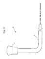
- Fig. 11 and Fig. 12 are reference diagrams: Fig. 11 is the block diagram of the overall structure of the refrigerant distribution device 3 wherein the bend of the inflow tube 8 is formed smoothly curved/radiused, or as an R bend; and Fig. 12 is the cross-sectional view of the bend of the inflow tube 8 in Fig. 11.
- ceiling suspension type As mentioned above, there are a ceiling suspension type, a ceiling cassette type, a wall mounted type, a floor standing type, and a ceiling-embedded type, and the like in large-sized air-conditioners. It is here explained an application to the ceiling suspension type as an example.
- a compressor for compressing a refrigerant In a refrigerant circuit (unshown) of a large-sized air-conditioner such as a ceiling suspension type, as is generally known, a compressor for compressing a refrigerant, a four way valve, an outdoor heat exchanger and a decompression device are mainly installed in an outdoor unit, and an indoor heat exchanger and a refrigerant distribution device are mainly installed in an indoor unit.
- a refrigerant compressed by the compressor to be at a high temperature and pressure is condensed by the outdoor heat exchanger to be a liquid refrigerant, then is decompressed by the decompression device to become a gas-liquid two-phase refrigerant, and flows into the indoor unit wherein the gas-liquid two-phase refrigerant first flows into the refrigerant distribution device.
- the gas-liquid two-phase refrigerant distributed in the refrigerant distribution device is evenly provided to the multi-path indoor heat exchanger.
- a centrifugal force acts on a liquid refrigerant of the gas-liquid two-phase refrigerant flows in the inflow tube 8 during cooling operation of the air-conditioner at the R bend in the bend part, and the liquid refrigerant unevenly concentrates in an outer periphery direction. Therefore, in the vertical part (rise part) located behind the bend, big bubbles concentrates on the inner side as shown in Fig. 12. If the length of the vertical portion is short, the refrigerant flows into the indoor heat exchanger in its state. Therefore, there is a problem that the refrigerant is not evenly distributed to the indoor heat exchanger.
- the bend of the inflow tube of the refrigerant distribution device is configured to be bent approximately at a right angle without forming R shape, whereof the longitudinal form is made of the combination of the straight lines, so that a centrifugal force does not act on the liquid refrigerant of the gas-liquid two-phase refrigerant and the liquid refrigerant does not spread unevenly.
- the indoor unit 1 of the ceiling suspension air-conditioner has an approximately rectangular casing with an external form short in height.
- An indoor air 20 is sucked in a fan 4 from a bottom surface of the casing, and sent to the heat exchanger 2 to be heat-exchanged with a refrigerant, then a secondary air heat-exchanged is blown off into a room from a front surface of the casing as an air discharged in a room 6.
- the refrigerant distribution device 3 for distributing and supplying the gas-liquid two-phase refrigerant to the heat exchanger 2 is installed at a portion to be an upper side of the heat exchanger 2 during cooling operation of the air-conditioner.
- a refrigerant sucked into a compressor of an outdoor unit is in a gaseous state, which is designated by a point a in Fig. 2 when illustrated in the Mollier chart.
- the refrigerant sucked in the compressor is compressed to be a high temperature and pressure gaseous refrigerant, and is discharged from the compressor.
- the refrigerant at the time is under a state designated by a point b in Fig. 2.
- the high temperature and pressure gaseous refrigerant is condensed by an outdoor unit heat exchanger to be a high pressure liquid refrigerant, then slightly supercooled and introduced to the decompression device.
- the refrigerant at the time is under a state designated by a point c in Fig. 2.
- the liquid refrigerant is expanded to be a gas-liquid two-phase refrigerant.
- the refrigerant at the time is under a state designated by a point d in Fig. 2.
- the gas-liquid two-phase refrigerant is flown into the refrigerant distribution device 3 of the indoor unit 1 for the ceiling suspension air-conditioner.
- the gas-liquid two-phase refrigerant distributed by the refrigerant distribution device 3 is evaporated in the heat exchanger 2, to be subject to gradual increase in dryness and slight rise in degree of superheat, and then returned to a suction inlet of the compressor (point a in Fig. 2).
- a dryness fraction of the gas-liquid two-phase refrigerant flows in the refrigerant distribution device 3 is generally about 0.2.
- the gas-liquid two-phase refrigerant with a dryness fraction of about 0.2 becomes a bubble flow in a horizontal tube (at a horizontal portion located ahead of the bend of the inflow tube 8 in the refrigerant distribution device 3), and an annular-mist flow or a froth flow in a vertical tube (at a vertical portion located behind the bend of the inflow tube 8 in the refrigerant distribution device 3).
- the refrigerant distribution device 3 includes an L-shaped inflow tube 8 wherein a gas-liquid two-phase refrigerant flows, and the distributor 7 connecting to the vertical portion located behind the bend of the inflow tube 8.
- the refrigerant distribution device 3 is characterized in that the longitudinal form of the bend of the inflow tube 8 is made of a combination of straight lines and bent approximately at a right angle. Therefore, there is no R bend in the bend part of the inflow tube 8.
- a gas-liquid two-phase refrigerant decompressed and generated at the decompression device of the outdoor unit during cooling operation of the air-conditioner flows in the horizontal portion (upstream portion) of the inflow tube 8 in the refrigerant distribution device 3 configured as above. Since a dryness fraction of the gas-liquid two-phase refrigerant flows in the inflow tube 8 is about 0.2, the gas-liquid two-phase refrigerant becomes a bubble flow in the horizontal portion. The gas-liquid two-phase refrigerant flows through the horizontal portion as the bubble flow reaches the bend in due course.
- the longitudinal form of the bend is made of a combination of straight lines and bent approximately at a right angle; therefore, a centrifugal force does not act on the refrigerant, and the refrigerant collides with an opposing wall 9 of the bend. Since the centrifugal force does not act, a liquid phase and a gas phase having different specific gravities are not acted upon by different external forces. Therefore, a biased distribution of large bubbles in an annular-mist flow or a froth flow is prevented in the vertical portion of the inflow tube 8 connected to the distributor 7.
- the longitudinal form of the bend of the inflow tube 8 in the refrigerant distribution device 3 is made of a combination of straight lines and is bent approximately at a right angle, a centrifugal force does not act on the gas-liquid two-phase refrigerant in the bend of the inflow tube 8. Therefore, it is possible to prevent a biased distribution of the large bubbles in the vertical portion of the inflow tube 8 connected to the distributor 7, and to eliminate an unevenness of refrigerant distribution to each path of the heat exchanger 2.
- Fig. 7 through Fig. 9 are diagrams illustrating the second embodiment: Fig. 7 is the longitudinal sectional view of the bend of the inflow tube 8 in the refrigerant distribution device 3; Fig. 8 is the perspective view of the refrigerant distribution device 3; and Fig. 9 is the exploded perspective view of the refrigerant distribution device 3.
- the longitudinal form of the bend of the inflow tube 8 in the refrigerant distribution device 3 is made of a combination of straight lines and is bent approximately at a right angle as in the first embodiment, and additionally as shown in Fig. 7, a depression 10 is established at a part where the opposing wall 9 facing a gas-liquid two-phase refrigerant flows in horizontally is formed.
- the depression 10 is formed by allowing the horizontal portion of the inflow tube 8 to bulge to an opposite side of a side from which the gas-liquid two-phase refrigerant flows in.
- Fig. 8 is the perspective view of the refrigerant distribution device 3.
- Fig. 9 is the exploded perspective view of the refrigerant distribution device 3.
- a connecting copper tube 12 is connected to one connection port at a head of a T-tube 11, while the other connection port at the head of the T-tube 11 is sealed to form the opposing wall 9 and the depression 10.
- the distributor 7 is connected to a connection port at a foot of the T-tube 11. In this way the refrigerant distribution device 3 is produced.
- connection ports openings
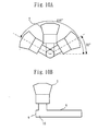
- Fig. 10A and Fig. 10B are diagrams illustrating the third embodiment: Fig. 10A is the diagram of the refrigerant distribution device 3 viewed from the opposing wall 9 side; and 10B is the schematic diagram of the overall structure of the refrigerant distribution device 3.
- the refrigerant distribution device with the aforementioned structure enables eliminating an unevenness of a liquid refrigerant at the bend of the inflow tube due to a centrifugal force.
Landscapes
- Engineering & Computer Science (AREA)
- Physics & Mathematics (AREA)
- Mechanical Engineering (AREA)
- Thermal Sciences (AREA)
- General Engineering & Computer Science (AREA)
- Heat-Exchange Devices With Radiators And Conduit Assemblies (AREA)
- Air Filters, Heat-Exchange Apparatuses, And Housings Of Air-Conditioning Units (AREA)
Abstract
The present invention aims to provide a refrigerant distribution device which eliminates a need for maintaining a certain length of a straight portion at an inflow tube to a distributor, and for adjusting lengths of capillary tubes to send a refrigerant to each flow path of the refrigerant of a heat exchanger, and which resolves an unevenness of a liquid refrigerant at a bend of the inflow tube due to a centrifugal force. A refrigerant distribution device according to the present invention including an inflow tube, which is connected to a distributor for distributing and providing a refrigerant in a gas-liquid two-phase state to a heat exchanger, wherein an upstream side of the inflow tube is in an approximately horizontal position and a downstream side of the inflow tube is bent to stand approximately at a right angle, includes a bend of the inflow tube, a longitudinal form of which is made of a combination of straight lines and is bent approximately at a right angle.
Description
- The present invention relates to a gas-liquid two-phase refrigerant distribution device (hereinafter referred to as a refrigerant distribution device in this specification) established in a refrigerant flow path of an air-conditioner and the like. The air-conditioner to be applied the refrigerant distribution device is a large-sized one, such as a ceiling suspension type, a ceiling cassette type, a wall mounted type, a floor standing type, and a ceiling embedded type. In this specification, an application to a ceiling suspension type is explained as an example.
- In a conventional refrigerant distribution device, at an R bend of an inflow tube wherein a gas-liquid two-phase refrigerant flows just ahead of a distributor whereto a plurality of capillary tubes or copper tubes toward each refrigerant flow path of a heat exchanger are connected, a liquid phase refrigerant with a higher specific gravity is subject to a centrifugal force higher than a gas phase refrigerant, so that the liquid refrigerant unevenly concentrates in an periphery direction of the R bend. Therefore, to prevent the unevenness of the liquid refrigerant, there is a need to maintain a certain length of a straight portion at the inflow tube from the R bend to the distributor.
When it is impossible to maintain a certain length of the straight portion at the inflow tube, it is necessary to eliminate the unevenness in the distributor. Therefore, there is a need to lengthen the lengths of the capillary tubes to each of the refrigerant flow paths coming out of the distributor, or to establish a plurality of capillary tubes for each refrigerant flow paths (for example, refer toJP 01-159571 - A conventional refrigerant distribution device has a problem to be a factor in preventing miniaturization of a main body of an air-conditioner, since there is a need to maintain a certain length of a straight portion at an inflow tube on a downstream side of an R bend to eliminate an unevenness of a liquid refrigerant occurred at the R bend due to a centrifugal force.
- The present invention aims to solve the aforementioned problem. It is one of the purposes of the present invention to provide a refrigerant distribution device wherein it is unnecessary to maintain a certain length of a straight portion at an inflow tube toward the distributor, and to adjust lengths of capillary tubes for sending a refrigerant to each of the refrigerant flow paths of the heat exchanger, and it is possible to eliminate an unevenness of the liquid refrigerant at a bend of the inflow tube due to a centrifugal force.
- This is achieved according to the present invention by forming the inflow tube with an upstream and a downstream portion, the downstream portion connecting to the distributor, and the upstream and downstream portions being joined in such a way that the refrigerant does not follow a single smoothly curved flow path around the join. Thus the flow does not subject the refrigerant to centrifugal force. Instead the flow from upstream to downstream portions may be comprise local flows from different directions or non-smooth, or turbulent, or non-laminar flows. This may be achieved by the join providing flow paths in the upstream and downstream portions which join in sharp angles as formed by a combination of straight lines.
- The refrigerant distribution device according to the present invention includes an inflow tube which is connected to a distributor for distributing and providing a refrigerant in a gas-liquid two-phase state to a heat exchanger, wherein an upstream side of the inflow tube is in an approximately horizontal position and a downstream side of the inflow tube is bent to stand approximately at a right angle, includes a bend of the inflow tube, a longitudinal form of which is made of a combination of straight lines and is bent approximately at a right angle.
- The invention will be further described by way of example with reference to the accompanying drawings, wherein:
- Fig. 1 is a diagram illustrating a first embodiment, and is a cross-sectional view of an
indoor unit 1 of a ceiling suspension air-conditioner whereto arefrigerant distribution device 3 is applied; - Fig. 2 is a diagram illustrating the first embodiment, and is a Mollier chart for a refrigerant;
- Fig. 3 is a diagram illustrating the first embodiment, and is a diagram showing flow patterns of an unheated upward two-phase flow in a vertical tube;
- Fig. 4 is a diagram illustrating the first embodiment, and is a diagram showing flow patterns of an unheated two-phase flow in a horizontal tube;
- Fig. 5 is a diagram illustrating the first embodiment, and is a schematic diagram of an overall structure of the
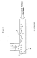
refrigerant distribution device 3; - Fig. 6 is a diagram illustrating the first embodiment, and is a longitudinal sectional view of a bend of an
inflow tube 8 in therefrigerant distribution device 3; - Fig. 7 is a diagram illustrating a second embodiment, and is a longitudinal sectional view of the bend of the
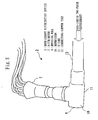
inflow tube 8 in therefrigerant distribution device 3; - Fig. 8 is a diagram illustrating the second embodiment, and is a perspective view of the
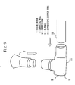
refrigerant distribution device 3; - Fig. 9 is a diagram illustrating the second embodiment, and is an exploded perspective view of the
refrigerant distribution device 3; - Fig. 10A is a diagram illustrating a third embodiment, and is a diagram of the
refrigerant distribution device 3 viewed from anopposing wall 9 side; - Fig. 10B is a diagram illustrating a third embodiment, and is a schematic diagram of an overall structure of the
refrigerant distribution device 3; - Fig. 11 is a reference diagram and is a block diagram of an overall structure of the
refrigerant distribution device 3 wherein the bend of theinflow tube 8 is formed to be an R bend; and - Fig. 12 is a reference diagram and is a cross-sectional view of the bend of the
inflow tube 8 in Fig. 11. - Fig. 1 through Fig. 6 are diagrams illustrating the first embodiment: Fig. 1 is the cross-sectional view of the
indoor unit 1 of a ceiling suspension air-conditioner whereto therefrigerant distribution device 3 is applied; Fig. 2 is the Mollier chart for a refrigerant; Fig. 3 is the diagram showing flow patterns of an unheated upward two-phase flow in a vertical tube; Fig. 4 is the diagram showing flow patterns of an unheated two-phase flow in a horizontal tube; Fig. 5 is the schematic diagram of the overall structure of therefrigerant distribution device 3; and Fig. 6 is the longitudinal sectional view of the bend of theinflow tube 8 in therefrigerant distribution device 3. - Fig. 11 and Fig. 12 are reference diagrams: Fig. 11 is the block diagram of the overall structure of the
refrigerant distribution device 3 wherein the bend of theinflow tube 8 is formed smoothly curved/radiused, or as an R bend; and Fig. 12 is the cross-sectional view of the bend of theinflow tube 8 in Fig. 11. - As mentioned above, there are a ceiling suspension type, a ceiling cassette type, a wall mounted type, a floor standing type, and a ceiling-embedded type, and the like in large-sized air-conditioners. It is here explained an application to the ceiling suspension type as an example.
- As a heat exchanger of an indoor unit for a large-sized air-conditioner such as a ceiling suspension type, one having a multi-path structure in which refrigerant circuits are generally divided into several circuits is used.
- In a refrigerant circuit (unshown) of a large-sized air-conditioner such as a ceiling suspension type, as is generally known, a compressor for compressing a refrigerant, a four way valve, an outdoor heat exchanger and a decompression device are mainly installed in an outdoor unit, and an indoor heat exchanger and a refrigerant distribution device are mainly installed in an indoor unit.
- During cooling operation of an air-conditioner, a refrigerant compressed by the compressor to be at a high temperature and pressure is condensed by the outdoor heat exchanger to be a liquid refrigerant, then is decompressed by the decompression device to become a gas-liquid two-phase refrigerant, and flows into the indoor unit wherein the gas-liquid two-phase refrigerant first flows into the refrigerant distribution device. The gas-liquid two-phase refrigerant distributed in the refrigerant distribution device is evenly provided to the multi-path indoor heat exchanger.
- In the
refrigerant distribution device 3 wherein the bent is formed to be an R bend as shown in the reference diagram Fig. 11, a centrifugal force acts on a liquid refrigerant of the gas-liquid two-phase refrigerant flows in theinflow tube 8 during cooling operation of the air-conditioner at the R bend in the bend part, and the liquid refrigerant unevenly concentrates in an outer periphery direction. Therefore, in the vertical part (rise part) located behind the bend, big bubbles concentrates on the inner side as shown in Fig. 12. If the length of the vertical portion is short, the refrigerant flows into the indoor heat exchanger in its state. Therefore, there is a problem that the refrigerant is not evenly distributed to the indoor heat exchanger. - In the present embodiment, the bend of the inflow tube of the refrigerant distribution device is configured to be bent approximately at a right angle without forming R shape, whereof the longitudinal form is made of the combination of the straight lines, so that a centrifugal force does not act on the liquid refrigerant of the gas-liquid two-phase refrigerant and the liquid refrigerant does not spread unevenly.
- It is hereinafter explained with reference to the diagrams of Fig. 1 through Fig. 6. In Fig. 1, the
indoor unit 1 of the ceiling suspension air-conditioner has an approximately rectangular casing with an external form short in height. Anindoor air 20 is sucked in afan 4 from a bottom surface of the casing, and sent to theheat exchanger 2 to be heat-exchanged with a refrigerant, then a secondary air heat-exchanged is blown off into a room from a front surface of the casing as an air discharged in a room 6. As for the refrigerant circuit, therefrigerant distribution device 3 for distributing and supplying the gas-liquid two-phase refrigerant to theheat exchanger 2 is installed at a portion to be an upper side of theheat exchanger 2 during cooling operation of the air-conditioner. - Operations in the refrigerant circuit during cooling operation of the air-conditioner are explained with reference to the Mollier chart in Fig. 2. A refrigerant sucked into a compressor of an outdoor unit (unshown) is in a gaseous state, which is designated by a point a in Fig. 2 when illustrated in the Mollier chart. The refrigerant sucked in the compressor is compressed to be a high temperature and pressure gaseous refrigerant, and is discharged from the compressor. When illustrated in the Mollier chart, the refrigerant at the time is under a state designated by a point b in Fig. 2. Further, the high temperature and pressure gaseous refrigerant is condensed by an outdoor unit heat exchanger to be a high pressure liquid refrigerant, then slightly supercooled and introduced to the decompression device. When illustrated in the Mollier chart, the refrigerant at the time is under a state designated by a point c in Fig. 2. In the decompression device, the liquid refrigerant is expanded to be a gas-liquid two-phase refrigerant. When illustrated in the Mollier chart, the refrigerant at the time is under a state designated by a point d in Fig. 2. The gas-liquid two-phase refrigerant is flown into the
refrigerant distribution device 3 of theindoor unit 1 for the ceiling suspension air-conditioner. The gas-liquid two-phase refrigerant distributed by therefrigerant distribution device 3 is evaporated in theheat exchanger 2, to be subject to gradual increase in dryness and slight rise in degree of superheat, and then returned to a suction inlet of the compressor (point a in Fig. 2). - The following is a brief description of flow patterns of a gas-liquid two-phase refrigerant, namely, flow patterns of a gas-liquid two-phase flow (adapted from "KIEKI-NISOURYU" (or "Gas-liquid two-phase flow"), Kouji Akagawa, Corona Publishing Co., LTD., Published on May 20, 1974).
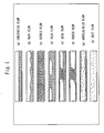
- There are five kinds of flow patterns of an unheated upward two-phase flow in a vertical tube as shown in Fig. 3. They represent the flow patterns in the vertical portion located behind the bend of the inflow tube 8 (described below) in the
refrigerant distribution device 3. The features of each flow pattern are described as follows: - (a) Bubble flow - A flow wherein small air bubbles are dispersed in a liquid phase;
- (b) Slug flow - A flow consists of alternating portions of those which includes bullet-shaped large bubbles surrounded by liquid films occupying almost the whole of a cross-section of a pipe line, and those which includes small bubbles in the liquid (liquid slug portion);
- (c) Froth flow - A flow including short liquid slug portions with a high gas content in which a liquid is reticulate;
- (d) Annular-mist flow - A flow wherein a liquid film is formed on a tube wall while liquid droplets are included in a core of a gas phase; and
- (e) Mist flow - A flow wherein a continuous liquid film is not formed on a tube wall while liquid droplets are included in a gas phase.
- On the other hand, there are eight kinds of flow patterns of an unheated two-phase flow in a horizontal tube, as shown in Fig. 4. Main features of each flow pattern which are different from those in the vertical tube are only described as follows:
- (a) Stratified flow - A flow wherein a gas and a liquid are separated in upper and lower two layers with approximately a flat and smooth interfacial boundary therebetween;
- (b) Wavy flow - A flow wherein an interfacial boundary between a gas and a liquid is wavy;
- (d) Plug flow - A flow wherein long large bubbles exist in an upper part of a flow path; and
- (e) Slug flow - A flow including a number of small bubbles at a liquid slug portion between large bubbles.
- As illustrated in the Mollier chart for a refrigerant in Fig. 2, a dryness fraction of the gas-liquid two-phase refrigerant flows in the
refrigerant distribution device 3 is generally about 0.2. The gas-liquid two-phase refrigerant with a dryness fraction of about 0.2 becomes a bubble flow in a horizontal tube (at a horizontal portion located ahead of the bend of theinflow tube 8 in the refrigerant distribution device 3), and an annular-mist flow or a froth flow in a vertical tube (at a vertical portion located behind the bend of theinflow tube 8 in the refrigerant distribution device 3). - With reference to Fig. 5 and Fig. 6, the structure and the operations of the
refrigerant distribution device 3 are described. Therefrigerant distribution device 3 includes an L-shapedinflow tube 8 wherein a gas-liquid two-phase refrigerant flows, and thedistributor 7 connecting to the vertical portion located behind the bend of theinflow tube 8. Therefrigerant distribution device 3 is characterized in that the longitudinal form of the bend of theinflow tube 8 is made of a combination of straight lines and bent approximately at a right angle. Therefore, there is no R bend in the bend part of theinflow tube 8. - A gas-liquid two-phase refrigerant decompressed and generated at the decompression device of the outdoor unit during cooling operation of the air-conditioner flows in the horizontal portion (upstream portion) of the
inflow tube 8 in therefrigerant distribution device 3 configured as above. Since a dryness fraction of the gas-liquid two-phase refrigerant flows in theinflow tube 8 is about 0.2, the gas-liquid two-phase refrigerant becomes a bubble flow in the horizontal portion. The gas-liquid two-phase refrigerant flows through the horizontal portion as the bubble flow reaches the bend in due course. In this case, the longitudinal form of the bend is made of a combination of straight lines and bent approximately at a right angle; therefore, a centrifugal force does not act on the refrigerant, and the refrigerant collides with an opposingwall 9 of the bend. Since the centrifugal force does not act, a liquid phase and a gas phase having different specific gravities are not acted upon by different external forces. Therefore, a biased distribution of large bubbles in an annular-mist flow or a froth flow is prevented in the vertical portion of theinflow tube 8 connected to thedistributor 7. - As shown above, since the longitudinal form of the bend of the
inflow tube 8 in therefrigerant distribution device 3 is made of a combination of straight lines and is bent approximately at a right angle, a centrifugal force does not act on the gas-liquid two-phase refrigerant in the bend of theinflow tube 8. Therefore, it is possible to prevent a biased distribution of the large bubbles in the vertical portion of theinflow tube 8 connected to thedistributor 7, and to eliminate an unevenness of refrigerant distribution to each path of theheat exchanger 2. - Fig. 7 through Fig. 9 are diagrams illustrating the second embodiment: Fig. 7 is the longitudinal sectional view of the bend of the
inflow tube 8 in therefrigerant distribution device 3; Fig. 8 is the perspective view of therefrigerant distribution device 3; and Fig. 9 is the exploded perspective view of therefrigerant distribution device 3. - In the second embodiment, the longitudinal form of the bend of the
inflow tube 8 in therefrigerant distribution device 3 is made of a combination of straight lines and is bent approximately at a right angle as in the first embodiment, and additionally as shown in Fig. 7, adepression 10 is established at a part where the opposingwall 9 facing a gas-liquid two-phase refrigerant flows in horizontally is formed. Thedepression 10 is formed by allowing the horizontal portion of theinflow tube 8 to bulge to an opposite side of a side from which the gas-liquid two-phase refrigerant flows in. - By establishing the
depression 10 at the part where the opposingwall 9 of the bend of theinflow tube 8 is formed, it is possible to restrain a rise velocity of a refrigerant at an outer periphery near the bend. Therefore, it is possible to prevent production of a turbulence of a refrigerant flow near the bend. The turbulence of the refrigerant flow leads to production of a pressure loss or a refrigerant noise in the refrigerant tube. Thus, by preventing the turbulence of the refrigerant flow, it is possible to suppress production of a pressure loss or a refrigerant noise in the refrigerant tube. - Fig. 8 is the perspective view of the
refrigerant distribution device 3. Fig. 9 is the exploded perspective view of therefrigerant distribution device 3. A connectingcopper tube 12 is connected to one connection port at a head of a T-tube 11, while the other connection port at the head of the T-tube 11 is sealed to form the opposingwall 9 and thedepression 10. Thedistributor 7 is connected to a connection port at a foot of the T-tube 11. In this way therefrigerant distribution device 3 is produced. - As mentioned above, by using the T-
tube 11 having connection ports (openings) in three directions, it is possible to produce easily therefrigerant distribution device 3 having a generally L-shaped overall configuration and including thedepression 10 at the part of the opposingwall 9 of the bend, without the need of bending the tube. - By including the depression at the part of the opposing
wall 9 of the bend, it is possible to restrain a rise velocity of a refrigerant at the outer periphery near the bend, and prevent production of a turbulence of a refrigerant flow near the bend. By preventing the turbulence of the refrigerant flow, it is possible to suppress production of a pressure loss or a refrigerant noise in the refrigerant tube. - Fig. 10A and Fig. 10B are diagrams illustrating the third embodiment: Fig. 10A is the diagram of the
refrigerant distribution device 3 viewed from the opposingwall 9 side; and 10B is the schematic diagram of the overall structure of therefrigerant distribution device 3. - According to "KIEKI-NISOURYU" (or "Gas-liquid two-phase flow") by Kouji Akagawa (as mentioned above), an upward flow in an inclined pipe also flows in virtually the same manner as the flow patterns in a vertical tube, if the inclined pipe has an inclination angle of 30 or more degrees relative to a horizontal plane. Therefore, when the
distributor 7 is inclined at an angle of 30 through 150 degrees with respect to a horizontal direction, the biased distribution of bubbles at an inlet to thedistributor 7 are prevented, as in a case of a vertical tube. By allowing thedistributor 7 to incline, it is possible to reduce the height of therefrigerant distribution device 3, and to limit the height (thickness) of the indoor unit of the ceiling suspension air-conditioner to a low level. - The refrigerant distribution device according to the present invention with the aforementioned structure enables eliminating an unevenness of a liquid refrigerant at the bend of the inflow tube due to a centrifugal force.
- Having thus described several particular embodiments of the present invention, various alterations, modifications, and improvements will readily occur to those skilled in the art within the scope of the present invention as defined in the following claims.
Claims (5)
- A refrigerant distribution device, including an inflow tube connected to a distributor for distributing and providing a refrigerant in a gas-liquid two-phase state to a heat exchanger, the inflow tube having an upstream portion and a downstream portion, the downstream portion of the inflow tube being approximately at a right angle to the upstream portion, and wherein:viewed in cross-section longitudinally of the inflow tube the walls of the upstream and downstream portions join in a combination of straight lines to achieve a bend approximately at a right angle.
- The refrigerant distribution device according to claim 1, further comprising:a depression formed near a wall which faces an inflow direction of a refrigerant to the bend.
- The refrigerant distribution device according to claim 2, further comprising a T-tube including connection ports in three directions,
wherein a connection port at a foot of the T-tube is connected to the distributor, and
wherein one connection port at a head of the T-tube is connected to a connecting copper tube forming an upstream side of the inflow tube, and the other connection port is sealed to form the depression near the bend. - The refrigerant distribution device according to claim 1, 2 or 3,
wherein the distributor is at an angle ranging from 30 through 150 degrees to the horizontal around a longitudinal axis of the upstream portion of the inflow tube - A refrigerant distribution device, including an inflow tube connected to a distributor for distributing and providing a refrigerant in a gas-liquid two-phase state to a heat exchanger, the inflow tube having an upstream portion and a downstream portion, the downstream portion of the inflow tube being approximately at a right angle to the upstream portion, and wherein the upstream and downstream portions join so as to define a non-progressive change in flow direction of the refrigerant.
Applications Claiming Priority (1)
| Application Number | Priority Date | Filing Date | Title |
|---|---|---|---|
| JP2006224255A JP2008045859A (en) | 2006-08-21 | 2006-08-21 | Refrigerant branching device |
Publications (1)
| Publication Number | Publication Date |
|---|---|
| EP1895250A1 true EP1895250A1 (en) | 2008-03-05 |
Family
ID=38664391
Family Applications (1)
| Application Number | Title | Priority Date | Filing Date |
|---|---|---|---|
| EP07253249A Withdrawn EP1895250A1 (en) | 2006-08-21 | 2007-08-17 | Refrigerant distribution device |
Country Status (3)
| Country | Link |
|---|---|
| US (1) | US20080041097A1 (en) |
| EP (1) | EP1895250A1 (en) |
| JP (1) | JP2008045859A (en) |
Cited By (1)
| Publication number | Priority date | Publication date | Assignee | Title |
|---|---|---|---|---|
| CN104776653A (en) * | 2014-01-13 | 2015-07-15 | 广东美的制冷设备有限公司 | Distributor for air conditioner and distributor component provided with distributor |
Families Citing this family (4)
| Publication number | Priority date | Publication date | Assignee | Title |
|---|---|---|---|---|
| US20110259551A1 (en) * | 2010-04-23 | 2011-10-27 | Kazushige Kasai | Flow distributor and environmental control system provided the same |
| JP5785468B2 (en) * | 2011-09-29 | 2015-09-30 | アズビル株式会社 | Gas-liquid two-phase fluid state control device and gas-liquid two-phase fluid state control method |
| KR101615445B1 (en) | 2014-08-14 | 2016-04-25 | 엘지전자 주식회사 | An air conditioner |
| CN106796067A (en) * | 2014-10-08 | 2017-05-31 | 三菱电机株式会社 | Refrigerant piping and heat pump assembly |
Citations (6)
| Publication number | Priority date | Publication date | Assignee | Title |
|---|---|---|---|---|
| US4341086A (en) * | 1980-10-06 | 1982-07-27 | Clarion Co., Ltd. | Refrigeration system |
| JPH01159571A (en) * | 1987-12-16 | 1989-06-22 | Mitsubishi Electric Corp | Multiphase fluid distributor |
| US4955210A (en) * | 1989-08-25 | 1990-09-11 | American Standard Inc. | Capillary tube assembly and method of manufacture |
| JPH03105178A (en) * | 1989-09-18 | 1991-05-01 | Nippondenso Co Ltd | Refrigerating and air-conditioning device |
| US5243838A (en) * | 1989-08-18 | 1993-09-14 | Matsushita Refrigeration Company | Refrigerant shunt |
| JP2003090646A (en) * | 2001-09-20 | 2003-03-28 | Hitachi Cable Ltd | Heat exchanger for air conditioner |
Family Cites Families (10)
| Publication number | Priority date | Publication date | Assignee | Title |
|---|---|---|---|---|
| US2168404A (en) * | 1935-05-23 | 1939-08-08 | Carrier Corp | Refrigerant distribution |
| US2126364A (en) * | 1937-07-14 | 1938-08-09 | Young Radiator Co | Evaporator distributor head |
| US4277953A (en) * | 1979-04-30 | 1981-07-14 | Kramer Daniel E | Apparatus and method for distributing volatile refrigerant |
| JPS5835371A (en) * | 1981-08-24 | 1983-03-02 | 株式会社日本アルミ | Evaporator for refrigerator, etc. |
| JP3216960B2 (en) * | 1994-09-19 | 2001-10-09 | 株式会社日立製作所 | Outdoor unit and indoor unit of air conditioner and refrigerant distributor used for them |
| US5617734A (en) * | 1995-03-27 | 1997-04-08 | Island Delite, Ltd. | Low temperature composition preparation device, and methods of constructing and utilizing same |
| JP3399257B2 (en) * | 1996-11-19 | 2003-04-21 | 松下電器産業株式会社 | Refrigerant branch pipe and air conditioner equipped with the refrigerant branch pipe |
| US5842351A (en) * | 1997-10-24 | 1998-12-01 | American Standard Inc. | Mixing device for improved distribution of refrigerant to evaporator |
| US5894741A (en) * | 1998-04-23 | 1999-04-20 | Parker-Hannifin Corporation | Universal housing body for an expansion device having a movable orifice piston for metering refrigerant flow |
| US7600393B2 (en) * | 2005-03-09 | 2009-10-13 | Lg Electronics Inc. | Refrigerant distributing device for multi-type air conditioner |
-
2006
- 2006-08-21 JP JP2006224255A patent/JP2008045859A/en active Pending
-
2007
- 2007-08-17 EP EP07253249A patent/EP1895250A1/en not_active Withdrawn
- 2007-08-20 US US11/841,042 patent/US20080041097A1/en not_active Abandoned
Patent Citations (6)
| Publication number | Priority date | Publication date | Assignee | Title |
|---|---|---|---|---|
| US4341086A (en) * | 1980-10-06 | 1982-07-27 | Clarion Co., Ltd. | Refrigeration system |
| JPH01159571A (en) * | 1987-12-16 | 1989-06-22 | Mitsubishi Electric Corp | Multiphase fluid distributor |
| US5243838A (en) * | 1989-08-18 | 1993-09-14 | Matsushita Refrigeration Company | Refrigerant shunt |
| US4955210A (en) * | 1989-08-25 | 1990-09-11 | American Standard Inc. | Capillary tube assembly and method of manufacture |
| JPH03105178A (en) * | 1989-09-18 | 1991-05-01 | Nippondenso Co Ltd | Refrigerating and air-conditioning device |
| JP2003090646A (en) * | 2001-09-20 | 2003-03-28 | Hitachi Cable Ltd | Heat exchanger for air conditioner |
Cited By (2)
| Publication number | Priority date | Publication date | Assignee | Title |
|---|---|---|---|---|
| CN104776653A (en) * | 2014-01-13 | 2015-07-15 | 广东美的制冷设备有限公司 | Distributor for air conditioner and distributor component provided with distributor |
| CN104776653B (en) * | 2014-01-13 | 2017-06-06 | 广东美的制冷设备有限公司 | Distributor for air-conditioner and the dispenser assembly with it |
Also Published As
| Publication number | Publication date |
|---|---|
| JP2008045859A (en) | 2008-02-28 |
| US20080041097A1 (en) | 2008-02-21 |
Similar Documents
| Publication | Publication Date | Title |
|---|---|---|
| JP6237068B2 (en) | Heat exchanger and air conditioner | |
| CN106716045B (en) | Heat exchanger and air-conditioning device | |
| CN105593628B (en) | Heat exchangers and air conditioning units | |
| US11913689B2 (en) | Heat exchanger and heat pump device | |
| US20150362222A1 (en) | Refrigerant distribution device and a heat pump apparatus using the same refrigerant distribution device | |
| AU2017351537A1 (en) | Indoor unit and air-conditioning apparatus | |
| JPWO2019058540A1 (en) | Refrigerant distributor and air conditioner | |
| EP1895250A1 (en) | Refrigerant distribution device | |
| WO2013094082A1 (en) | Outdoor unit and refrigeration cycle device with outdoor unit | |
| CN116324305A (en) | Distributors, heat exchangers and air conditioning units | |
| JP2001116396A (en) | Refrigerant distributor, refrigeration cycle device and air conditioner using the same | |
| CN112567193B (en) | Heat exchanger and air conditioner | |
| CN106949681B (en) | Suction Line Flow Control for Lubricant Management | |
| EP2597384A2 (en) | Outdoor unit for air conditioner | |
| JP2015127620A (en) | Heat exchanger and air conditioner | |
| WO2018185840A1 (en) | Heat exchanger and refrigeration cycle device | |
| JP6541881B2 (en) | Air conditioner, air conditioner and refrigeration cycle device | |
| JP2006336935A (en) | Refrigeration air conditioner outdoor unit | |
| JP2013002773A (en) | Heat exchanger and air conditioner with the same | |
| US11549721B2 (en) | Heat exchange unit and air-conditioning apparatus including the same | |
| CN110945299A (en) | Heat exchanger and refrigeration cycle device | |
| JP6667070B2 (en) | Refrigerant flow divider and refrigeration system using the same | |
| CN215373041U (en) | Evaporator input pipe assembly, air conditioner indoor unit and air conditioner | |
| CN115667813A (en) | Indoor unit of air conditioner | |
| JP7821412B2 (en) | Heat exchangers and air conditioners |
Legal Events
| Date | Code | Title | Description |
|---|---|---|---|
| PUAI | Public reference made under article 153(3) epc to a published international application that has entered the european phase |
Free format text: ORIGINAL CODE: 0009012 |
|
| AK | Designated contracting states |
Kind code of ref document: A1 Designated state(s): AT BE BG CH CY CZ DE DK EE ES FI FR GB GR HU IE IS IT LI LT LU LV MC MT NL PL PT RO SE SI SK TR |
|
| AX | Request for extension of the european patent |
Extension state: AL BA HR MK YU |
|
| AKX | Designation fees paid | ||
| REG | Reference to a national code |
Ref country code: DE Ref legal event code: 8566 |
|
| STAA | Information on the status of an ep patent application or granted ep patent |
Free format text: STATUS: THE APPLICATION IS DEEMED TO BE WITHDRAWN |
|
| 18D | Application deemed to be withdrawn |
Effective date: 20080906 |