EP1895196A2 - Differential gear for vehicle and assembling method of the same - Google Patents
Differential gear for vehicle and assembling method of the same Download PDFInfo
- Publication number
- EP1895196A2 EP1895196A2 EP07114007A EP07114007A EP1895196A2 EP 1895196 A2 EP1895196 A2 EP 1895196A2 EP 07114007 A EP07114007 A EP 07114007A EP 07114007 A EP07114007 A EP 07114007A EP 1895196 A2 EP1895196 A2 EP 1895196A2
- Authority
- EP
- European Patent Office
- Prior art keywords
- gears
- side gears
- pinion
- differential case
- pair
- Prior art date
- Legal status (The legal status is an assumption and is not a legal conclusion. Google has not performed a legal analysis and makes no representation as to the accuracy of the status listed.)
- Granted
Links
Images







Classifications
-
- F—MECHANICAL ENGINEERING; LIGHTING; HEATING; WEAPONS; BLASTING
- F16—ENGINEERING ELEMENTS AND UNITS; GENERAL MEASURES FOR PRODUCING AND MAINTAINING EFFECTIVE FUNCTIONING OF MACHINES OR INSTALLATIONS; THERMAL INSULATION IN GENERAL
- F16H—GEARING
- F16H57/00—General details of gearing
- F16H57/04—Features relating to lubrication or cooling or heating
- F16H57/048—Type of gearings to be lubricated, cooled or heated
- F16H57/0482—Gearings with gears having orbital motion
- F16H57/0483—Axle or inter-axle differentials
-
- F—MECHANICAL ENGINEERING; LIGHTING; HEATING; WEAPONS; BLASTING
- F16—ENGINEERING ELEMENTS AND UNITS; GENERAL MEASURES FOR PRODUCING AND MAINTAINING EFFECTIVE FUNCTIONING OF MACHINES OR INSTALLATIONS; THERMAL INSULATION IN GENERAL
- F16H—GEARING
- F16H48/00—Differential gearings
- F16H48/06—Differential gearings with gears having orbital motion
- F16H48/08—Differential gearings with gears having orbital motion comprising bevel gears
-
- F—MECHANICAL ENGINEERING; LIGHTING; HEATING; WEAPONS; BLASTING
- F16—ENGINEERING ELEMENTS AND UNITS; GENERAL MEASURES FOR PRODUCING AND MAINTAINING EFFECTIVE FUNCTIONING OF MACHINES OR INSTALLATIONS; THERMAL INSULATION IN GENERAL
- F16H—GEARING
- F16H48/00—Differential gearings
- F16H48/06—Differential gearings with gears having orbital motion
- F16H48/08—Differential gearings with gears having orbital motion comprising bevel gears
- F16H2048/085—Differential gearings with gears having orbital motion comprising bevel gears characterised by shafts or gear carriers for orbital gears
-
- F—MECHANICAL ENGINEERING; LIGHTING; HEATING; WEAPONS; BLASTING
- F16—ENGINEERING ELEMENTS AND UNITS; GENERAL MEASURES FOR PRODUCING AND MAINTAINING EFFECTIVE FUNCTIONING OF MACHINES OR INSTALLATIONS; THERMAL INSULATION IN GENERAL
- F16H—GEARING
- F16H48/00—Differential gearings
- F16H48/38—Constructional details
- F16H2048/382—Methods for manufacturing differential gearings
-
- F—MECHANICAL ENGINEERING; LIGHTING; HEATING; WEAPONS; BLASTING
- F16—ENGINEERING ELEMENTS AND UNITS; GENERAL MEASURES FOR PRODUCING AND MAINTAINING EFFECTIVE FUNCTIONING OF MACHINES OR INSTALLATIONS; THERMAL INSULATION IN GENERAL
- F16H—GEARING
- F16H48/00—Differential gearings
- F16H48/38—Constructional details
- F16H2048/387—Shields or washers
Definitions
- This invention relates to a differential gear for a vehicle, whose plural pinion gears are supported by pinion gear supporters of a differential case, and an assembling method of the differential gear.
- Japanese patent application publication No. 2006-46642 discloses a differential gear which has a pair of pinion gears of the so-called "shaftless type.”
- the differential gear comprises the pair of pinion gears, a differential case rotated by the engine torque, a pair of side gears engaging with each of the pinion gears in the differential case and a pair of thrust washers respectively receiving thrust forces of the side gears.
- Each pinion gear has a supported portion and an engaging portion all around, and is arranged on the line normal to a rotational axis of the differential case.
- the differential case has a pair of holes for a pair of right and left drive shafts and a pair of holes for the pair of pinion gears.
- Each hole for the pinion gear has a first supporting surface to support the supported portion of the pinion gear.
- the hole for the pinion is inwardly elongated to form a second supporting surface to support a part of the engaging portion of the pinion gear.
- Each side gear is a substantially circular bevel gear whose outer diameter is larger than the pinion gear's and is arranged on the rotational axis of the differential case.
- the inner surface of the side gear is spline-engaged with the drive shaft.
- Each thrust washer is interposed between the back face of the side gear and the inner periphery of the hole for the drive shaft. The engagement of the pair of pinion gears and side gears is adjusted during the assembly of the differential gear.
- the differential case is rotated about the rotational axis by the engine torque via a drive pinion and a ring gear. Due to the rotation of the differential gear, the torque is transmitted to the pair of pinion gears and further to the pair of side gears. Because the side gears are respectively spline-engaged with the drive shafts, the engine torque is distributed to the pair of right and left drive shafts according to the driving situation through the drive pinion, ring gear, differential case, pinion gears and side gears.
- the pinion gears are inserted into the differential case to be supported by the respective holes for the pinion gears.
- the side gears are inserted into the differential case to align their axes with the rotational axis of the differential case.
- the thrust washers are then interposed between the back of the side gears and the inner peripheries of the holes for the drive shafts respectively.
- the pair of side gears engages with the pair of pinion gears.
- the right and left drive shafts are inserted into and spline-engaged with the side gears.
- the thrust washers are not fixed in position before connection with the drive shafts. Therefore, the thrust washers may move radially from their predetermined positions prior to the drive shaft connection, so that the operator must correct the position of the thrust washers at that time. As a result, the process may be complicated.
- a differential gear for a vehicle comprises a differential case, plural pinion gears, a pair of side gears and a pair of thrust washers.
- the differential case has plural support portions to support the pinion gears and a pair of holes for drive shafts.
- the side gears engage with the pinion gears.
- Each thrust washer is interposed between the back of a respective side gear and the periphery of a respective hole of the differential case, wherein the thrust washers are prevented from radial movement when the side gears are not connected with the respective drive shafts.
- the differential case has plural support portions to support plural pinion gears and a pair of holes for drive shafts;
- the method comprises steps of inserting the pinion gears into the differential case and supporting the pinion gears at the support portions; inserting a pair of side gears into the differential case to align their axes with a rotational axis of the drive shafts; engaging the side gears with the pinion gears; and interposing a pair of thrust washers between the backs af the side gears and the peripheries of each hole of the differential case respectively, wherein the thrust washers are prevented from radial movement when the side gears are not connected with the respective drive shafts.
- Figs. 1 to 13 show a differential gear 1 that comprises a differential case 2, a pair of (upper and lower) pinion gears 3 and 4, a pair of (right and left) side gears 5R and 5L, and a pair of (right and left) thrust washers 6R and 6L.
- the differential case 2 is rotated by the engine torque.
- the pinion gears 3, 4 are symmetrically arranged on a line perpendicular to a rotational axis O of the differential case 2.
- the side gears 5R,5L are symmetrically arranged on the rotational axis O of the differential case 2 and engage with the pinion gears 3, 4.
- Each thrust washer 6R, 6L is arranged on the back of a respective side gear 5R, 5L.
- the differential case 2 as shown in Figs. 5 and 6, is formed as one piece and has an internal space 2A, a concavity 2B, lubricant oil inlets 7 and 8, and lubricant oil reservoir 30.
- the space 2A holds the pinion gears 3, 4, side gears 5R, 5L and thrust washers 6R, 6L.
- the concavity 2B connects with the space 2A.
- the lubricant oil inlets 7, 8 introduce lubricant oil between sliding surfaces (described hereafter as first supported portions 3a, 4a of base ends B and second supported portions 3b, 4b of gear portions C) of the pinion gear 3, 4 and supporting surfaces (described hereafter as pinion gear supporting surfaces 10a, 11a of pinion gear back holes 10A, 11 A and pinion gear supporting surfaces 10b, 11b of extensions 10B, 11B) of pinion gear supporters 10, 11.
- the lubricant oil reservoir 30 stores the lubricant oil to supply to the sliding surfaces of the pinion gear 3, 4.
- the lubricant oil inlets 7, 8 are respectively constructed by the pinion gears 3, 4 and projections 7a, 8a to stir the lubricant oil (differential oil).
- the projections 7a, 8a as shown in Figs. 4, 7 and 8, are respectively integrated with the extensions 10B, 11B (described hereafter) that extend from the differential case 2 toward its rotational axis O and are disposed to hold both sides of the pinion gears 3, 4 about the rotational axis O.
- Spaces 7b, 8b between the projections 7a, 8a and the pinion gears 3, 4 open to the rotational axis O of the differential case 2 and around the axes of the pinion gear supporters 10, 11, so as to introduce the lubricant oil.
- the lubricant oil reservoir 30, as shown in Figs. 6(a) and 6(b), is a circular concavity surrounding the rotational axis O on the inner surface ofthe differential case 2 and is placed close to the pinion gear supporters 10,11 (see Fig. 5).
- the distance "b" between the radially outer wall of the reservoir 30 and the rotational axis O is substantially the same to the distance "a" between the first supported portions 3a, 4a and the rotational axis O so as to permit the lubricant oil (differential oil) L to lubricate the first supported portions 3a, 4a.
- the lubricant oil L is subjected to centrifugal force so as to be stored in the radially outer portion of the reservoir 30.
- the lubricant oil is supplied to the first supported portions 3a, 4a of the pinion gears 3, 4 so as to lubricate these portions.
- the lubricant oil reservoir 30 spreads stress occurring at feet of the pinion supporters 10, 11 so that the differential case 2 is strengthened mechanically.
- the differential case 2 as shown in Figs. 2 and 5, has a pair of (right and left) holes 9R, 9L for drive shafts opening along the rotational axis O and a pair of (upper and lower) the pinion supporters 10, 11 whose axes are perpendicular to the axes of the holes 9R, 9L.
- the differential case 2 has side gear passing holes 12R, 12L arranged symmetrically about the rotational axis O (see Fig. 1) and equiangularly from the pinion supporters 10, 11.
- the differential case 2, as shown in Figs. 1 to 3, further comprises a flange 13 for a ring gear at the left side.
- the flange 13 is circular on the plane perpendicular to the rotational axis O.
- the holes 9R, 9L for the drive shafts as shown in Figs. 2 and 3, form penetrating holes whose inner diameters are substantially equal.
- a pair of (right and left) drive shafts 29 are respectively inserted into the pair of the holes 9R, 9L (Fig. 11 shows one of them).
- a pair of spherical seats 9Ra, 9La for the thrust washers 6R, 6L are respectively formed at the peripheries of the holes 9R, 9L on the inner surface of the differential case 2.
- the pinion gear supporters 10, 11, as shown in Figs. 5 and 8, are respectively comprised by the pinion gear back holes 10A, 11A and the extensions 10B, 11B.
- the pinion gear back holes 10A, 11A, as shown in Fig. 6(a), respectively form step-like holes to support the pinion gears 3, 4 and have notches 10d, 11d connecting with the reservoir 30.
- the pinion gear back holes 10A, 11A respectively have inner openings whose inner diameters are substantially the same as the outer diameters of the pinion gears 3, 4.
- the inner surfaces of the pinion gear back holes 10A, 11A respectively form the pinion gear supporting surfaces 10a, 11a in order to support the first supported portions 3a, 4a of the pinion gears 3,4. As shown in Figs.
- spherical pinion gear seats "m” and “n” are respectively formed with predetermined curvature at first step surfaces of the pinion gear back holes 10A, 11A so as to bear the pinion gears 3, 4 receiving centrifugal force.
- Washer seats 10c, 11c are respectively formed at second step surfaces of the back holes 10A, 11A to receive washers 21, 22.
- the washers 21, 22, as shown in Figs. 5 and 6, are respectively interposed between the back of the pinion gears 3,4 and the washer seats 10c, 11c.
- the washers 21, 22 respectively close the pinion back holes 10A, 11A so as to block the lubricant oil receiving centrifugal force by the rotation of the differential case 2.
- the extensions 10B, 11B are equiangularly aligned and extend inwardly (toward the rotational axis O of the differential case 2) at the peripheries of the pinion gear back holes 10A, 11A, respectively.
- the extensions 10B, 11B have the pinion gear supporting surfaces 10b, 11b that connect with the pinion gear, supporting surfaces 10a, 11 a and support a part of the first supported portions 3a, 4a and the second supported portions 3b, 4b (a part of engaging portion with the side gears).
- the side gear passing holes 12R, 12L as shown in Figs. 3 to 5, have noncircular openings.
- the openings of the holes 12R, 12L have sufficient size to insert the pinion gears 3, 4 and the side gears 5R, 5L into the differential case 2.
- the pinion gear 3 is a substantially cylindrical and so-called shaftless type gear that comprises a base end B and a gear portion C.
- the base end B has a circumferential surface with a predetermined outer diameter.
- the gear portion C has teeth C1 and grooves C2 arranged alternately.
- the pinion gear 3 is rotatably supported by the pinion gear supporter 10a of the pinion back hole 10A and the pinion gear supporter 10b of the extension 10B.
- the base end B of the pinion gear 3 has the first supported portion 3a and plural lubricant grooves 3C.
- the first supported portion 3a works as a sliding surface on the pinion gear supporter 10a of the pinion back hole 10A.
- the lubricant grooves 3C work as openings to the sliding surface of the first supported portion 3a in order to introduce the lubricant oil there.
- the lubricant grooves 3C of the pinion gear 3 are arranged equiangularly. When the pinion gear 3 revolves (the differential case 2 rotates), the lubricant grooves 3C hold the lubricant oil and introduce it to the clearance between the first supported portion 3a and the pinion gear supporters 10a, 10b.
- the lubricant grooves 3C extend longitudinally along the rotational axis of the pinion gear 3 and open to at least one ofthe sides of the pinion gear seat "m" and the rotational axis O of the differential case 2, the lubricant oil flows to the back of the pinion gear 3 by centrifugal force when the pinion gear 3 revolves.
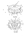
- the pinion gear 3 as shown in Figs. 10(a) and 10(b), further comprises a penetrating bore 3A along its axis.
- the penetrating bore 3A works as a centering bore when forming the gear, a rod insert bore when storing the gear in a storage and a lubricant oil supply bore when using the differential gear.
- the side opposite the base end B of the pinion gear 3 is engages with the side gears 5R, 5L, except at the gear portion C.
- the first supported portion 3a is at the circumferential surface of the base end B, and is supported by the pinion gear supporter 10a of the back hole 10A and the pinion gear supporter 10b of the extension 10B.
- a spherical sliding portion 3B is provided at the back face of the pinion gear 3 so as to slide on the pinion gear seat "m" of the pinion gear back hole 10A.
- the gear portion C as shown in 10(a) and 10(b), has straight portions Cs and taper portions Ct.
- the straight portions Cs include the second supported portion 3b of the pinion gear 3 at their circumferential surfaces.
- the taper portions Ct connect with the straight portions Cs.
- the gear portion C engages with the side gears 5R, 5L toward the rotational axis of the differential case 2.
- Tops "c" of teeth C1 of the gear portion C have circumferential surfaces with a predetermined outer diameter, and have cone-like circumferential surfaces whose outer diameter reduces toward the tip of the gear.
- the side gears 5R, 5L are substantially circular gears that have boss portions 5Ra, 5La and gear portions 5Rb, 5Lb, respectively.
- the side gears 5Ra, 5La are bevel gears which have larger outer diameters than the pinion gears 3, 4 and the same conical angle of the top teeth.
- the side gears 5R, 5L are rotatably supported in the differential case 2 and engage with the pinion gears 3, 4.
- the number of teeth of the side gears 5R, 5L is 2.1 times or more than that of the pinion gears 3, 4. For example, the number of teeth of the side gears 5R, 5L is fifteen and that of the pinion gears 3, 4 is seven.
- the surfaces of the side gears 5R, 5L form spherical sliding portions 5Rc, 5Lc which conform to the seats 9Ra, 9La via the thrust washers 6R, 6L, respectively.
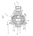
- the side gears 5R, 5L as shown in Fig. 11, respectively have bores 9R, 9L which are spline-connected with the drive shafts 29.
- the spaces G work as paths 28 to supply the lubricant oil.
- Figs. 2 and 3 show an axle spacer 23 interposed between the side gears 5R, 5L.
- the axle spacer 23, as shown in Figs. 3 and 12, is substantially cylindrical and has a pair of (right and left) concavities 23a, 23b into which fit the tips of the drive shafts 29.
- the axle spacer 23 is arranged around the rotational axis O of the differential case 2 so as to provide smooth and reliable spline-connections between the drive shafts 29 and the side gears 5R, 5L.
- Bearing surfaces 23A, 23B are formed on the bottoms of the concavities 23a, 23b so as to support the tips of the drive shafts 29.
- the axle spacer 23 has flattened portions 24,25 which are planes 24a, 25a parallel to a hypothetical plane passing through its axis.
- the flattened portions 24, 25, as shown in Fig. 3, are equiangularly arranged on the circumferential surface of the axle spacer 23. Therefore, when the differential case 2 rotates, the flattened portions 24, 25 stir the lubricant oil which is thus well introduced to the first supported portions 3a, 4a of the pinion gears 3, 4. Further lubricant oil is supplied to the first supported portions 3a, 4a of the pinion gears 3, 4, because the flattened portions 24, 25 fluidically connect with the outside ofthe differential case 2 through the paths 28 (see Fig. 11).
- the thrust washers 6R, 6L are circular washers that have ring portions 6Ra, 6La receiving thrust forces of the side gears 5R, 5L, respectively.
- the thrust washers 6R, 6L are interposed between the backs of the side gears 5R, 5L and the seats 9Ra, 9La for the thrust washers, and conform to the engagement between side gears 5R, 5L and the pinion gears 3, 4.
- Each thrust washer 6R, 6L has lock tongues 26, 27 at its periphery, which are equiangular and extend outwardly.
- the lock tongues 26, 27 lock the outer surfaces of the side gears 5R, 5L by their plastic deformation.
- the lock tongues 26, 27 allow the side gears 5R, 5L to rotate and prevent the thrust washers 6R, 6L from moving radially relative to the side gears 5R, 5L. Deformed onto the side gears 5R, 5L plastically, the thrust washers 6R, 6L are integrated with the side gears 5R, 5L. Thus when the drive shafts 29 are inserted into the side gears 5R, 5L, the thrust washers 6R, 6L are not displaced from the side gears 5R, 5L radially, so that the number of the processes required to insert the drive shafts 29 is reduced. Therefore the process to insert the drive shafts is simplified to reduce the cost.
- the thickness of each lock tongue 26, 27 is smaller than that of each ring portion 6Ra, 6La.
- Such dimension lets the lock tongues 26, 27 be filly deformed so as to simplify combining the thrust washers 6R, 6L with the side gears 5R, 5L.
- the lock tongues 26, 27 may be removed after the drive shafts 29 inserted, because the lock tongues 26, 27 have no further function.
- the engine torque is input to the differential case 2 through a drive pinion and a ring gear, so as to rotate the differential case 2 about the rotational axis O.
- the rotational force of the differential case 2 is transmitted to the pinion gears 3, 4 and then is transmitted to the side gears 5R, 5L via the pinion gears 3, 4.
- the drive shafts 29 are respectively spline-engaged with the side gears 5R, 5L, and therefore the engine torque is transmitted to the right and left drive shafts 29 via the drive pinion, ring gear, differential case 2, pinion gears 3, 4 and side gears 5R, 5L.
- the rotation of the differential case 2 causes lubrication of the pinion gears 3, 4 and the pinion gear supporters 10, 11 as explained in (1) to (4) below.
- the engine torque is transmitted to the differential case 2.
- the pinion gears 3, 4 revolve about the rotational axis O of the differential case 2 and then the side gears 5R, 5L rotate with the differential case 2 unitedly. Therefore the engine torque is equally divided to the right and left drive shafts 29, and the right and left wheels are rotated at the same speed.
- the pinion gears 3, 4 rotate and relatively revolve.
- the engine torque is unequally divided to the right and left drive shafts 29, and the right and left wheels are rotated at different speed.
- the first and second supported portions 3a, 4a, 3b, 4b of the pinion gears 3, 4 slide on the pinion gear supporting surfaces 10a, 11a, 10b, 11b so that frictional resistance occurs therebetween.
- the frictional resistance limits the differential rotation between the right and left side gears 5R, 5L.
- the rotations of the pinion gears 3, 4 also cause thrust forces of respective pinion and side gears 3, 4, 5R, 5L at the engagement portions.
- the side gears 5R, 5L are moved away from each other by the thrust forces and press the thrust washers 6R, 6L to the seats 9Ra, 9La so that further frictional resistance occurs therebetween.
- the frictional resistance also limits the differential rotation between the right and left side gears 5R, 5L.
- the thrust forces for the pinion gears 3, 4 cause the pinion gears 3, 4 be pressed to the seats "m", "n”. This produces frictional resistance against the rotations of the pinion gears 3, 4.
- the frictional resistance also limits the differential rotation between the right and left side gears 5R, 5L.
- Fig. 14 is an explanatory section view of the side gear assembling process in the assembling method of the differential gear 1 of the first embodiment.
- Figs. 15(a) to 15(d) are step-by-step explanatory schematic plan views of the assembling method.
- the assembling method of the differential gear 1 comprises inserting the pinion gears 3, 4 (first step), inserting the side gears 5R, 5L (second step), engaging the pinion gears 3, 4 with the side gears 5R, 5L (third step) and positioning the thrust washers 6R, 6L (fourth step) sequentially.
- the pinion gears 3, 4 are inserted into the differential case 2 through the side gear passing holes 12R, 12L. Then the pinion gears 3, 4 are moved to where the slide portions 3B, 4B contact the pinion gear seats "m", "n” so as to be supported by the pinion gear supporters 10, 11 at the predetermined positions, as shown in Fig. 5.
- the side gears 5R, 5L are inserted into the differential case 2 though the side gear passing holes 12R, 12L and moved toward the thrust washer seats 9Ra, 9La. Then the axes of the side gears 5R, 5L are aligned on the rotational axis O of the differential case 2, as shown in Fig. 14. At this time, the teeth of the side gears 5R, 5L may clash with the teeth of the pinion gears 3, 4. However, as shown in Figs. 15(a) to 15(d), the side gears 5R, 5L are rotated relative to each other in opposite directions to rotate the pinion gears 3, 4 during the insertion, so that the side gears 5R, 5L are smoothly inserted into the differential case 2. Then the side gears 5R, 5L are aligned on the rotational axis O so as to be set in the differential case 2.
- the thrust washers 6R, 6L are interposed between the sliding portions 5Ra, 5La of the side gears 5R, 5L and the thrust washer seats 9Ra, 9La around the holes 9R, 9L for the drive shafts 29.
- the side gears 5R, 5L are engaged with the pinion gears 3, 4.
- the axle spacer 23 is interposed between the pair of the side gears 5R.5L during the engagement.
- the lock tongues 26, 27 of the thrust washers 6R, 6L are deformed in order to lock the thrust washers 6R, 6L on the circumferences of the side gears 5R, 5L.
- the thrust washers 6R, 6L are fixed on the backs of the side gears 5R, 5L.
- the shape of the lock tongues is not limited to that shown in Fig. 1.
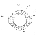
- the thrust washers 40 may have T-shaped lock tongues 40a, 40b as shown in Fig. 16.
- the thrust washers 40 shown in Figs. 17(a) and 17(b) contact the backs of the side gears 5R, 5L
- the lock tongues 40a, 40b are deformed so as to be locked to the side gears 5R, 5L.
- the thrust washers 40 shown in Fig. 16 have paths 40A in order to permit the lubricant oil to flow outward.
- the lubricant oil is well supplied to the pinion gears 3, 4.
- the lock tongues 26, 27, 40a, 40b of the thrust washers 6R, 6L, 40 are locked to the side gears 5R, 5L explained above, the lock tongues may be locked to the differential case.
- the differential case may have the lock tongues locked to the thrust washers.
- the side gears may have the lock tongues locked to the thrust washers. The important point is that the thrust washers are interposed between the side gears and the differential case and are kept locking to the side gears or the differential case.
- the differential gear 100 comprises a pair of restriction rings 101R, 101L which restrict respective radial movement of the thrust washers 6R, 6L.
- the restriction rings 101R, 101L are interposed between the backs of the side gears 5R, 5L and the peripheries of the inner openings of the holes 9R, 9L for the drive shafts 29, and are inserted into the thrust washers 6R, 6L.
- the restriction rings 101R, 101L are snap rings (elastic rings).
- the inner openings of the holes 9R, 9L have first spaces 102 R, 102L to hold one ends of the restriction rings 101R, 101L.
- the outer surfaces of the restriction rings 101R, 101L press the inner surfaces of the first spaces 102R, 102L.
- the inner openings on the backs of the side gears 5R, 5L have second spaces 103R, 103L to hold the other ends of the restriction rings 101R, 101L.
- the inner diameters D1 of the second spaces 103R, 103L are larger than the inner diameters D2 of the first spaces 102R, 102L (D1>D2).
- the restriction rings 101R, 101L do not press to the inner surfaces of the second spaces 103R, 103L.
- the assembling method of the differential gear 100 comprises inserting the pinion gears 3, 4 (first step), inserting the side gears 5R, 5L (second step), engaging the pinion gears 3, 4 with the side gears 5R, 5L (third step) and positioning the thrust washers 6R, 6L (fourth step) sequentially.
- the steps of inserting the pinion gears 3, 4, inserting the side gears 5R, 5L and engaging the pinion gears 3, 4 with the side gears 5R, 5L are substantially the same to the first embodiment. Thus the explanation of these three steps will be omitted and positioning the thrust washers 6R, 5L will be explained below.
- the restriction rings 101R, 101L are diametrically compressed and are inserted into the holes 9R, 9L for the drive shafts 29 from the outer openings.
- the restriction rings 101R, 101L are further inserted into the thrust washers 6R, 6L and the side gears 5R, 5L.
- the restriction rings 101R, 101L are disposed to press on the surfaces of the first spaces 102R, 102L of the holes 9R, 9L at one ends but not to press on the surfaces of the second spaces 103R, 103L at the other ends.
- restriction rings 101R,101L are attached to the first spaces 102R, 102L so as to position the thrust washers 6R, 6L between the backs of the side gears 5R, 5L and thrust washer seats 9Rc, 9Lc without radial movement.
- the second embodiment gains the following advantage in addition to the advantages (1) to (5) of the first embodiment.
- restriction rings 101R, 101L are attached to the first spaces 102R, 102L during insertion so as to position the thrust washers 6R, 6L without radial movement. Therefore no deformation of parts of the thrust washers is needed, so that the step of positioning the thrust washer is simplified.
- a differential gear I for a vehicle has a differential case 2 having a pair of holes 9R, 9L for drive shafts, a pair of pinion gears 3, 4 supported by pinion gear supporters 10, 11 and a pair of side gears 5R, 5L engaging with the pinion gears 3, 4.
- a pair of thrust washers 6R, 6L is interposed between the backs of the side gears 5R, 5L and the inner peripheries of the holes 9R, 9L. The thrust washers are prevented from radial movement when the side gears are not connected with the respective drive shafts.
Landscapes
- Engineering & Computer Science (AREA)
- General Engineering & Computer Science (AREA)
- Mechanical Engineering (AREA)
- Retarders (AREA)
- General Details Of Gearings (AREA)
Abstract
Description
- This invention relates to a differential gear for a vehicle, whose plural pinion gears are supported by pinion gear supporters of a differential case, and an assembling method of the differential gear.
-
Japanese patent application publication No. 2006-46642 - The differential case is rotated about the rotational axis by the engine torque via a drive pinion and a ring gear. Due to the rotation of the differential gear, the torque is transmitted to the pair of pinion gears and further to the pair of side gears. Because the side gears are respectively spline-engaged with the drive shafts, the engine torque is distributed to the pair of right and left drive shafts according to the driving situation through the drive pinion, ring gear, differential case, pinion gears and side gears.
- To assemble the differential gear, first the pinion gears are inserted into the differential case to be supported by the respective holes for the pinion gears. Next the side gears are inserted into the differential case to align their axes with the rotational axis of the differential case. The thrust washers are then interposed between the back of the side gears and the inner peripheries of the holes for the drive shafts respectively. Thus the pair of side gears engages with the pair of pinion gears. Finally the right and left drive shafts are inserted into and spline-engaged with the side gears.
- In the prior art, however, the thrust washers are not fixed in position before connection with the drive shafts. Therefore, the thrust washers may move radially from their predetermined positions prior to the drive shaft connection, so that the operator must correct the position of the thrust washers at that time. As a result, the process may be complicated.
- According to the invention, a differential gear for a vehicle comprises a differential case, plural pinion gears, a pair of side gears and a pair of thrust washers. The differential case has plural support portions to support the pinion gears and a pair of holes for drive shafts. The side gears engage with the pinion gears. Each thrust washer is interposed between the back of a respective side gear and the periphery of a respective hole of the differential case, wherein the thrust washers are prevented from radial movement when the side gears are not connected with the respective drive shafts.
- According to the invention, in an assembling method of a differential gear for a vehicle, the differential case has plural support portions to support plural pinion gears and a pair of holes for drive shafts; The method comprises steps of inserting the pinion gears into the differential case and supporting the pinion gears at the support portions; inserting a pair of side gears into the differential case to align their axes with a rotational axis of the drive shafts; engaging the side gears with the pinion gears; and interposing a pair of thrust washers between the backs af the side gears and the peripheries of each hole of the differential case respectively, wherein the thrust washers are prevented from radial movement when the side gears are not connected with the respective drive shafts.
- Various objects, features and many of the attendant advantages of the present invention will be readily appreciated as the same becomes better understood by reference to the following detailed description of the preferred embodiments when considered in connection with the accompanying drawings, in which:
- Fig. 1 is an exploded view of a differential gear for a vehicle in a first embodiment related to the invention,
- Fig. 2 is a longitudinal section view of the first embodiment,
- Fig. 3 is a cross section view of the first embodiment,
- Fig. 4 is a perspective view of a differential case supporting pinion gears of the first embodiment,
- Fig. 5 is a section view of Fig. 4 perpendicular to a rotational axis of the differential case,
- Fig. 6(a) is a section view of Fig. 4 parallel to the rotational axis of the differential case and Fig. 6(b) is an enlarged partial view of Fig. 6(a),
- Fig. 7 is a perspective view of a differential case of the first embodiment,
- Fig. 8 a section view of Fig. 7 perpendicular to a rotational axis of the differential case,
- Fig. 9 is a section view of Fig. 7 parallel to the rotational axis of the differential case,
- Figs. 10(a) and 10(b) are a perspective view of a pinion gear,
- Fig. 11 is a partial section view of connection a side gear with a drive shaft of the first embodiment,
- Fig. 12 is a perspective view of a spacer of the first embodiment,
- Fig. 13 is a partial section view of the first embodiment to describe how to supply lubricant oil,
- Fig. 14 is an explanatory section view of the side gear assembling process in an assembling method of the differential gear of the first embodiment,
- Figs. 15(a) to 15(d) are step-by-step explanatory schematic plan views of Fig. 14,
- Fig. 16 is a modification of a thrust washer of the first embodiment,
- Figs. 17(a) and 17(b) are explanatory drawings of the first embodiment to describe the thrust washer before its deformation,
- Figs. 18(a) and 18(b) are explanatory drawings of the first embodiment to describe the thrust washer after its deformation,
- Fig. 19 is a longitudinal section view of a second embodiment related to the invention, and
- Fig. 20 is a partial enlarged view of Fig. 19.
- A first embodiment of a differential gear for a vehicle and an assembling method of the same related to the present invention will be described with reference to Figs. 1 to 13. Figs. 1 to 13 show a
differential gear 1 that comprises adifferential case 2, a pair of (upper and lower)pinion gears side gears thrust washers differential case 2 is rotated by the engine torque. Thepinion gears differential case 2. Theside gears differential case 2 and engage with thepinion gears thrust washer respective side gear - The
differential case 2, as shown in Figs. 5 and 6, is formed as one piece and has aninternal space 2A, aconcavity 2B,lubricant oil inlets lubricant oil reservoir 30. Thespace 2A holds thepinion gears side gears thrust washers concavity 2B connects with thespace 2A. Thelubricant oil inlets portions portions pinion gear gear supporting surfaces gear back holes gear supporting surfaces extensions pinion gear supporters lubricant oil reservoir 30 stores the lubricant oil to supply to the sliding surfaces of thepinion gear - As shown in Fig. 5, the
lubricant oil inlets projections projections extensions differential case 2 toward its rotational axis O and are disposed to hold both sides of the pinion gears 3, 4 about the rotationalaxis O. Spaces projections differential case 2 and around the axes of thepinion gear supporters - The
lubricant oil reservoir 30, as shown in Figs. 6(a) and 6(b), is a circular concavity surrounding the rotational axis O on the inner surface ofthedifferential case 2 and is placed close to thepinion gear supporters 10,11 (see Fig. 5). The distance "b" between the radially outer wall of thereservoir 30 and the rotational axis O is substantially the same to the distance "a" between the first supportedportions portions differential case 2 rotates, the lubricant oil L is subjected to centrifugal force so as to be stored in the radially outer portion of thereservoir 30. Thus the lubricant oil is supplied to the first supportedportions lubricant oil reservoir 30 spreads stress occurring at feet of thepinion supporters differential case 2 is strengthened mechanically. - The
differential case 2, as shown in Figs. 2 and 5, has a pair of (right and left) holes 9R, 9L for drive shafts opening along the rotational axis O and a pair of (upper and lower) thepinion supporters holes differential case 2 has sidegear passing holes pinion supporters differential case 2, as shown in Figs. 1 to 3, further comprises aflange 13 for a ring gear at the left side. Theflange 13 is circular on the plane perpendicular to the rotational axis O. Theholes drive shafts 29 are respectively inserted into the pair of theholes thrust washers holes differential case 2. - The
pinion gear supporters extensions notches reservoir 30. The pinion gear back holes 10A, 11A respectively have inner openings whose inner diameters are substantially the same as the outer diameters of the pinion gears 3, 4. The inner surfaces of the pinion gear back holes 10A, 11A respectively form the piniongear supporting surfaces portions Washer seats washers washers washer seats washers differential case 2. Thus the lubricant oil is prevented from flowing out from thedifferential case 2 through the back holes 10A, 11A. As shown in Figs. 5 and 8, theextensions extensions gear supporting surfaces surfaces portions portions - The side
gear passing holes holes differential case 2. - Because the pinion gears 3, 4 are substantially the same, only the
pinion gear 3 will be described. Thepinion gear 3, as shown in Figs. 10(a) and 10(b), is a substantially cylindrical and so-called shaftless type gear that comprises a base end B and a gear portion C. The base end B has a circumferential surface with a predetermined outer diameter. The gear portion C has teeth C1 and grooves C2 arranged alternately. As shown in Fig. 5, thepinion gear 3 is rotatably supported by thepinion gear supporter 10a of the pinion backhole 10A and thepinion gear supporter 10b of theextension 10B. - The base end B of the
pinion gear 3 has the first supportedportion 3a and plural lubricant grooves 3C. The first supportedportion 3a works as a sliding surface on thepinion gear supporter 10a of the pinion backhole 10A. The lubricant grooves 3C work as openings to the sliding surface of the first supportedportion 3a in order to introduce the lubricant oil there. The lubricant grooves 3C of thepinion gear 3 are arranged equiangularly. When thepinion gear 3 revolves (thedifferential case 2 rotates), the lubricant grooves 3C hold the lubricant oil and introduce it to the clearance between the first supportedportion 3a and thepinion gear supporters portion 3a of thepinion gear 3 as the sliding surface so that the first supportedportion 3a will not seize. In addition, because the lubricant grooves 3C extend longitudinally along the rotational axis of thepinion gear 3 and open to at least one ofthe sides of the pinion gear seat "m" and the rotational axis O of thedifferential case 2, the lubricant oil flows to the back of thepinion gear 3 by centrifugal force when thepinion gear 3 revolves. - The
pinion gear 3, as shown in Figs. 10(a) and 10(b), further comprises a penetratingbore 3A along its axis. Thus heat treatment affects not only the outside but also inside of thepinion gear 3 so that thepinion gear 3 is strengthened mechanically. The penetratingbore 3A works as a centering bore when forming the gear, a rod insert bore when storing the gear in a storage and a lubricant oil supply bore when using the differential gear. - The side opposite the base end B of the
pinion gear 3 is engages with the side gears 5R, 5L, except at the gear portion C. The first supportedportion 3a is at the circumferential surface of the base end B, and is supported by thepinion gear supporter 10a of theback hole 10A and thepinion gear supporter 10b of theextension 10B. A spherical slidingportion 3B, as shown in Figs. 10(a) and 10(b), is provided at the back face of thepinion gear 3 so as to slide on the pinion gear seat "m" of the pinion gear backhole 10A. The gear portion C, as shown in 10(a) and 10(b), has straight portions Cs and taper portions Ct. The straight portions Cs include the second supportedportion 3b of thepinion gear 3 at their circumferential surfaces. The taper portions Ct connect with the straight portions Cs. The gear portion C engages with the side gears 5R, 5L toward the rotational axis of thedifferential case 2. Tops "c" of teeth C1 of the gear portion C have circumferential surfaces with a predetermined outer diameter, and have cone-like circumferential surfaces whose outer diameter reduces toward the tip of the gear. - The side gears 5R, 5L, as shown in Fig. 2, are substantially circular gears that have boss portions 5Ra, 5La and gear portions 5Rb, 5Lb, respectively. In detail, the side gears 5Ra, 5La are bevel gears which have larger outer diameters than the pinion gears 3, 4 and the same conical angle of the top teeth. The side gears 5R, 5L are rotatably supported in the
differential case 2 and engage with the pinion gears 3, 4. The number of teeth of the side gears 5R, 5L is 2.1 times or more than that of the pinion gears 3, 4. For example, the number of teeth of the side gears 5R, 5L is fifteen and that of the pinion gears 3, 4 is seven. The surfaces of the side gears 5R, 5L form spherical sliding portions 5Rc, 5Lc which conform to the seats 9Ra, 9La via thethrust washers drive shafts 29. There are certain equiangularly spaced spaces G made by missing teeth at the spline-connections 5Ra, 5La between the side gears 5R, 5L and thedrive shafts 29. The spaces G work aspaths 28 to supply the lubricant oil. - Figs. 2 and 3 show an
axle spacer 23 interposed between the side gears 5R, 5L. Theaxle spacer 23, as shown in Figs. 3 and 12, is substantially cylindrical and has a pair of (right and left)concavities drive shafts 29. Theaxle spacer 23 is arranged around the rotational axis O of thedifferential case 2 so as to provide smooth and reliable spline-connections between thedrive shafts 29 and the side gears 5R, 5L. Bearing surfaces 23A, 23B are formed on the bottoms of theconcavities drive shafts 29. Theaxle spacer 23 has flattenedportions 24,25 which areplanes portions 24, 25, as shown in Fig. 3, are equiangularly arranged on the circumferential surface of theaxle spacer 23. Therefore, when thedifferential case 2 rotates, the flattenedportions 24, 25 stir the lubricant oil which is thus well introduced to the first supportedportions portions portions 24, 25 fluidically connect with the outside ofthedifferential case 2 through the paths 28 (see Fig. 11). - The thrust washers 6R, 6L, as shown in Figs. 1 to 3, are circular washers that have ring portions 6Ra, 6La receiving thrust forces of the side gears 5R, 5L, respectively. The thrust washers 6R, 6L are interposed between the backs of the side gears 5R, 5L and the seats 9Ra, 9La for the thrust washers, and conform to the engagement between side gears 5R, 5L and the pinion gears 3, 4. Each
thrust washer tongues lock tongues lock tongues thrust washers thrust washers drive shafts 29 are inserted into the side gears 5R, 5L, thethrust washers drive shafts 29 is reduced. Therefore the process to insert the drive shafts is simplified to reduce the cost. The thickness of eachlock tongue lock tongues thrust washers lock tongues drive shafts 29 inserted, because thelock tongues - Next, the operation of the
differential gear 1 will be described. The engine torque is input to thedifferential case 2 through a drive pinion and a ring gear, so as to rotate thedifferential case 2 about the rotational axis O. The rotational force of thedifferential case 2 is transmitted to the pinion gears 3, 4 and then is transmitted to the side gears 5R, 5L via the pinion gears 3, 4. Thedrive shafts 29 are respectively spline-engaged with the side gears 5R, 5L, and therefore the engine torque is transmitted to the right and leftdrive shafts 29 via the drive pinion, ring gear,differential case 2, pinion gears 3, 4 and side gears 5R, 5L. - The rotation of the
differential case 2 causes lubrication of the pinion gears 3, 4 and thepinion gear supporters - (1) During the rotation of the
differential case 2, lubricant oil is pressed onto the inner cylindrical surface of thedifferential case 2 by centrifugal force. As shown in Fig. 13, because thedifferential case 2 has theinternal lubrication inlets 7, 8 (Fig. 13 shows one of them) for theprojections projections spaces portions portions pinion gear supporters 10, 11 (the piniongear supporting surfaces gear supporting surfaces extensions surfaces - (2) As shown in Figs. 6(a) and 6(b), the
differential case 2 has the internallubricant oil reservoir 30 at the concavity surrounding the rotational axis O. Centrifugal force causes the lubricant oil L to flow radially outward in thereservoir 30. Thus the lubricant oil L is introduced to and lubricates the first supportedportions notches reservoir 30. - (3) As shown in Figs. 10(a) and 10(b), the pinion gears 3, 4 have the first supported
portions gear supporting surfaces extensions gear supporting surfaces portions differential case 2, the lubricant oil is introduced into the lubricant grooves 3C so as to be supplied to, and lubricate, the regions between the first supportedportions gear supporting surfaces - (4) The
axle spacer 23 interposed between the side gears 5R, 5L has the flattenedportions 24, 25 with theplanes portions gear supporting surfaces portions 24, 25 through the clearance between theholes differential case 2 and thedrive shafts 29, so as to be further supplied therebetween. - Next, the operation of the
differential gear 1 will be described. The engine torque is transmitted to thedifferential case 2. Where the same loads are given to respective wheels connected with the right and leftdrive shafts 29, the pinion gears 3, 4 revolve about the rotational axis O of thedifferential case 2 and then the side gears 5R, 5L rotate with thedifferential case 2 unitedly. Therefore the engine torque is equally divided to the right and leftdrive shafts 29, and the right and left wheels are rotated at the same speed. - Meanwhile, when the vehicle turns to the right/left or one of the wheels slips, the pinion gears 3, 4 rotate and relatively revolve. Thus the engine torque is unequally divided to the right and left
drive shafts 29, and the right and left wheels are rotated at different speed. In the event of the rotation of the pinion gears 3, 4 during the torque loads to thedifferential case 2, the first and second supportedportions gear supporting surfaces thrust washers - Next, there will be described an example of an assembling method of the
differential gear 1 according to the first embodiment with reference to Figs. 2, 3, 5, 14 and 15. Fig. 14 is an explanatory section view of the side gear assembling process in the assembling method of thedifferential gear 1 of the first embodiment. Figs. 15(a) to 15(d) are step-by-step explanatory schematic plan views of the assembling method. The assembling method of thedifferential gear 1 comprises inserting the pinion gears 3, 4 (first step), inserting the side gears 5R, 5L (second step), engaging the pinion gears 3, 4 with the side gears 5R, 5L (third step) and positioning thethrust washers - The pinion gears 3, 4 are inserted into the
differential case 2 through the sidegear passing holes slide portions pinion gear supporters - The side gears 5R, 5L are inserted into the
differential case 2 though the sidegear passing holes differential case 2, as shown in Fig. 14. At this time, the teeth of the side gears 5R, 5L may clash with the teeth of the pinion gears 3, 4. However, as shown in Figs. 15(a) to 15(d), the side gears 5R, 5L are rotated relative to each other in opposite directions to rotate the pinion gears 3, 4 during the insertion, so that the side gears 5R, 5L are smoothly inserted into thedifferential case 2. Then the side gears 5R, 5L are aligned on the rotational axis O so as to be set in thedifferential case 2. - While adjusting the clearance between the thrust washer seats 9Ra, 9La and the side gears 5R, 5L, as shown in Fig. 3, the
thrust washers holes drive shafts 29. When the interposition of thethrust washers drive shafts 29 with the side gears 5R, 5L (the spline connection), theaxle spacer 23 is interposed between the pair of the side gears 5R.5L during the engagement. - The
lock tongues thrust washers thrust washers thrust washers - The above described first embodiment gains following advantages.
- (1) The lubricant oil is well supplied to the base end of the pinion gears 3, 4 (between the first supported
portions pinion gear supporters - (2) The
projections lubricant oil inlet portions pinion gear supporters - (3) The
lubricant oil reservoir 30 is a concavity surrounding the rotational axis O of thedifferential case 2 beside thepinion gear supporters reservoir 30 disperses stresses at the feet of thepinion gear supporters differential case 2. - (4) Because the
thrust washers deformable lock tongues thrust washers lock tongues drive shafts 29 are fully inserted into the side gears 5R, 5L, thethrust washers drive shafts 29 is reduced so as to simple the connecting processes of the drive shafts and reduce the cost. - (5) There are spaces G provided by the missing teeth at the spline-connections 5Rc, 5Lc between the inner surfaces of the side gears 5R, 5L and the outer surfaces of the
drive shafts 29. The lubricant oil is introduced into thedifferential case 2 from the outside through theholes portions pinion gear supporters - Incidentally, the shape of the lock tongues is not limited to that shown in Fig. 1. For example, the
thrust washers 40 may have T-shapedlock tongues thrust washers 40 shown in Figs. 17(a) and 17(b) contact the backs of the side gears 5R, 5L, thelock tongues paths 40A in order to permit the lubricant oil to flow outward. Thus the lubricant oil is well supplied to the pinion gears 3, 4. - Although the
lock tongues thrust washers - A second embodiment of the differential gear for the vehicle related to the present invention will be described with reference to Figs. 19 and 20. In Figs. 19 and 20, the same/equivalent parts will be indicated by the same reference numbers/symbols as in Figs. 1 to 15 and the explanation of those parts will be omitted.
- As shown in Fig. 19, the
differential gear 100 comprises a pair of restriction rings 101R, 101L which restrict respective radial movement of thethrust washers holes drive shafts 29, and are inserted into thethrust washers holes first spaces first spaces second spaces second spaces first spaces second spaces - Next, the assembling method of the second embodiment will be described with reference to Fig. 19. The assembling method of the
differential gear 100 comprises inserting the pinion gears 3, 4 (first step), inserting the side gears 5R, 5L (second step), engaging the pinion gears 3, 4 with the side gears 5R, 5L (third step) and positioning thethrust washers thrust washers - As shown in Fig. 19, the restriction rings 101R, 101L are diametrically compressed and are inserted into the
holes drive shafts 29 from the outer openings. The restriction rings 101R, 101L are further inserted into thethrust washers first spaces holes second spaces first spaces thrust washers - The second embodiment gains the following advantage in addition to the advantages (1) to (5) of the first embodiment.
- The restriction rings 101R, 101L are attached to the
first spaces thrust washers - Obviously, numerous modifications and variations of the present invention are possible in light of the above teachings. It is thereby to be understood that within the scope of the appended claims, the present invention may be practiced otherwise than as specifically described herein.
- (1) For example, although the described
differential case 2 is one piece, the differential case may have plural case elements. - (2) For example, although the described differential gear has a pair of the pinion gears 3, 4 in the
differential case 2, three pinion gears may be disposed in thedifferential case 2. In this case, the pinion gears are preferentially smaller. - A differential gear I for a vehicle has a
differential case 2 having a pair ofholes pinion gear supporters thrust washers holes
Claims (16)
- A differential gear for a vehicle, comprising:a differential case having plural pinion gear supporters extending inwardly of the case, and a pair of holes for drive shafts;plural pinion gears slidably supported by the respective pinion gear supporters;a pair of side gears engaging with the pinion gears and adapted to be connected with respective drive shafts; anda pair of thrust washers respectively interposed between backs of the side gears and peripheries of the holes for the drive shafts, wherein the thrust washers are prevented from radial movement when the side gears are not connected with the respective drive shafts.
- The differential gear according to claim 1, wherein the thrust washers have portions defining paths to permit lubricant oil to flow radially outward of the thrust washers.
- The differential gear according to claim 1, wherein the thrust washers are prevented from radial movement by lock portions of the thrust washers, the side gears or the differential case.
- The differential gear according to claim 3, wherein the lock portions are deformable lock tongues.
- The differential gear according to claim 4, wherein each said thrust washer has a plurality of equiangularly spaced lock tongues.
- The grinding method according to claim 3, wherein the lock portions are disposed to allow rotation of the side gears.
- The differential gear according to claim 1,
wherein the thrust washers are prevented from radial movement by restriction rings, and
wherein the restriction rings are interposed between backs of the side gears and peripheries of the holes for the drive shafts, and are inserted into the thrust washers. - The differential gear according to claim 7,
wherein the differential case has first spaces at inner peripheries of the holes to hold one ends of the restriction rings, and
wherein the side gears have second spaces on the backs to hold the other ends of the restriction rings. - The differential gear according to claim 8, wherein the restriction rings are attached to the first spaces.
- The differential gear according to claim 9, wherein the restriction rings press to inner surfaces of the first spaces.
- The differential gear according to claim 1, wherein the pinion gears are shaftless pinion gears.
- The differential gear according to claim 1, wherein the pinion gear supporters are extended from an inner surface of the differential case.
- An assembling method of a differential gear for a vehicle, comprising:a first step of inserting plural pinion gears into a differential case having a pair of holes for drive shafts;a second step of inserting a pair of side gears into the differential case with alignment of axes of the drive shafts and the side gears;a third step of engaging the side gears with the pinion gears and of interposing a pair of thrust washers having lock tongues between backs af the side gears and peripheries of the holes; anda fourth step of locking the lock tongues to the side gears.
- The assembling method according to claim 13, wherein, in the second step, the side gears are moved to rotate the pinion gears during inserting into the differential case.
- An assembling method of a differential gear for a vehicle, comprising:a first step of inserting plural pinion gears into a differential case having a pair of holes for drive shafts;a second step of inserting a pair of side gears into the differential case with alignment of axes of the drive shafts and the side gears;a third step of engaging the side gears with the pinion gears and interposing a pair of thrust washers between backs of the side gears and peripheries of the holes; anda fourth step of inserting restriction rings to inner opening of the holes so as to prevent the thrust washers from radial movement.
- The assembling method according to claim 15, wherein, in the second step, the side gears are moved to rotate the pinion gears during inserting into the differential case.
Applications Claiming Priority (2)
| Application Number | Priority Date | Filing Date | Title |
|---|---|---|---|
| JP2006231099 | 2006-08-28 | ||
| JP2007039425A JP4888151B2 (en) | 2006-08-28 | 2007-02-20 | Vehicle differential and its assembly method |
Publications (3)
| Publication Number | Publication Date |
|---|---|
| EP1895196A2 true EP1895196A2 (en) | 2008-03-05 |
| EP1895196A3 EP1895196A3 (en) | 2010-01-20 |
| EP1895196B1 EP1895196B1 (en) | 2012-02-08 |
Family
ID=38621027
Family Applications (1)
| Application Number | Title | Priority Date | Filing Date |
|---|---|---|---|
| EP07114007A Ceased EP1895196B1 (en) | 2006-08-28 | 2007-08-08 | Differential gear for vehicle and assembling method of the same |
Country Status (3)
| Country | Link |
|---|---|
| US (1) | US7976421B2 (en) |
| EP (1) | EP1895196B1 (en) |
| JP (1) | JP4888151B2 (en) |
Cited By (2)
| Publication number | Priority date | Publication date | Assignee | Title |
|---|---|---|---|---|
| WO2022187474A1 (en) * | 2021-03-05 | 2022-09-09 | Polaris Industries Inc. | A mechanical differential assembly |
| US11892067B2 (en) | 2021-03-05 | 2024-02-06 | Polaris Industries Inc. | Vehicle system |
Families Citing this family (13)
| Publication number | Priority date | Publication date | Assignee | Title |
|---|---|---|---|---|
| US8216105B2 (en) * | 2007-11-02 | 2012-07-10 | Jtekt Corporation | Differential apparatus for vehicle and assembling method thereof |
| CN102937172B (en) * | 2012-11-19 | 2015-07-29 | 上汽通用五菱汽车股份有限公司 | A kind of end cap of racing car differential mechanism |
| JP6481261B2 (en) * | 2014-04-16 | 2019-03-13 | 株式会社ジェイテクト | Vehicle differential |
| JP6487664B2 (en) * | 2014-10-22 | 2019-03-20 | 武蔵精密工業株式会社 | Differential |
| JP6146439B2 (en) * | 2015-05-18 | 2017-06-14 | トヨタ自動車株式会社 | Differential gear assembly method and differential gear assembly apparatus |
| JP6651838B2 (en) * | 2015-12-22 | 2020-02-19 | 株式会社ジェイテクト | Driving force distribution device |
| JP2019152266A (en) * | 2018-03-02 | 2019-09-12 | 本田技研工業株式会社 | Differential device |
| JP6982529B2 (en) * | 2018-03-22 | 2021-12-17 | 本田技研工業株式会社 | Differential device |
| US10767754B2 (en) | 2018-05-30 | 2020-09-08 | American Axle & Manufacturing, Inc. | Driveline component with differential assembly and differential lubrication device |
| JP6625778B1 (en) * | 2019-06-06 | 2019-12-25 | 株式会社ショーワ | Differential case |
| US11384830B2 (en) * | 2019-08-06 | 2022-07-12 | Toyota Motor Engineering & Manufacturing North America, Inc. | Window design for a differential housing |
| WO2022107223A1 (en) * | 2020-11-17 | 2022-05-27 | 武蔵精密工業株式会社 | Differential device |
| JP2024165316A (en) * | 2023-05-17 | 2024-11-28 | トヨタ自動車株式会社 | Differential Mechanism |
Citations (10)
| Publication number | Priority date | Publication date | Assignee | Title |
|---|---|---|---|---|
| GB207729A (en) | 1923-02-06 | 1923-12-06 | Timken Axle Co Detroit | Improvements in differential constructions for the driving axles of motor vehicles |
| US2364411A (en) | 1943-01-21 | 1944-12-05 | Deere & Co | Differential gear |
| JPS57129949A (en) | 1981-02-05 | 1982-08-12 | Mazda Motor Corp | Differential gear device |
| JPS58137643A (en) | 1982-02-08 | 1983-08-16 | Nissan Motor Co Ltd | Differential gear apparatus |
| JPS63235126A (en) | 1987-03-24 | 1988-09-30 | Kubota Ltd | differential gear |
| JPH02105637U (en) | 1989-02-10 | 1990-08-22 | ||
| US5584777A (en) | 1994-05-18 | 1996-12-17 | Dr. Ing. H.C.F. Porsche Ag | Differential cage for absorbing shock mounted in a differential casing |
| DE19637120C1 (en) | 1996-09-12 | 1998-01-29 | Porsche Ag | Differential gear for motor vehicle |
| DE102004003643A1 (en) | 2004-01-24 | 2005-08-11 | Zf Friedrichshafen Ag | New design of differential for vehicle, comprising asymmetrically joined basket and lid |
| JP2006046642A (en) | 2004-07-09 | 2006-02-16 | Toyoda Mach Works Ltd | Differential gear device for vehicle |
Family Cites Families (13)
| Publication number | Priority date | Publication date | Assignee | Title |
|---|---|---|---|---|
| US2945400A (en) * | 1959-03-18 | 1960-07-19 | Dupras Louis | Self locking differential |
| US3264901A (en) * | 1964-05-22 | 1966-08-09 | Rockwell Standard Co | Limited slip differential |
| US3406592A (en) * | 1966-10-07 | 1968-10-22 | Tecumseh Products Co | Differential |
| JPS5926644A (en) * | 1982-08-04 | 1984-02-10 | Nissan Motor Co Ltd | Differential gear device |
| US4667534A (en) * | 1985-10-18 | 1987-05-26 | Tochigi-Fuji Sangyo Kabushiki Kaisha | Limited slip differential gear mechanism |
| DE3706217A1 (en) * | 1987-02-26 | 1988-09-08 | Iveco Magirus | LUBRICATION DEVICE FOR THE DIFFERENTIAL GEARBOX OF MOTOR VEHICLES |
| JP2918891B2 (en) | 1988-10-14 | 1999-07-12 | 日本電気株式会社 | In-band signaling device |
| US6076644A (en) * | 1998-06-05 | 2000-06-20 | Auburn Gear, Inc. | Conical clutch member having recessed areas for use in a limited slip differential |
| JP4356850B2 (en) * | 1999-09-02 | 2009-11-04 | 本田技研工業株式会社 | Differential |
| JP2003254415A (en) * | 2002-02-28 | 2003-09-10 | Komatsu Ltd | Clutch type limited slip differential |
| JP4815889B2 (en) | 2005-06-17 | 2011-11-16 | 株式会社ジェイテクト | Differential gear device for vehicle |
| JP2006349117A (en) * | 2005-06-17 | 2006-12-28 | Jtekt Corp | Differential gear device for vehicle |
| JP4706431B2 (en) | 2005-10-21 | 2011-06-22 | 株式会社ジェイテクト | Vehicle differential, vehicle hybrid differential, and vehicle differential case |
-
2007
- 2007-02-20 JP JP2007039425A patent/JP4888151B2/en not_active Expired - Fee Related
- 2007-08-08 EP EP07114007A patent/EP1895196B1/en not_active Ceased
- 2007-08-27 US US11/845,443 patent/US7976421B2/en not_active Expired - Fee Related
Patent Citations (10)
| Publication number | Priority date | Publication date | Assignee | Title |
|---|---|---|---|---|
| GB207729A (en) | 1923-02-06 | 1923-12-06 | Timken Axle Co Detroit | Improvements in differential constructions for the driving axles of motor vehicles |
| US2364411A (en) | 1943-01-21 | 1944-12-05 | Deere & Co | Differential gear |
| JPS57129949A (en) | 1981-02-05 | 1982-08-12 | Mazda Motor Corp | Differential gear device |
| JPS58137643A (en) | 1982-02-08 | 1983-08-16 | Nissan Motor Co Ltd | Differential gear apparatus |
| JPS63235126A (en) | 1987-03-24 | 1988-09-30 | Kubota Ltd | differential gear |
| JPH02105637U (en) | 1989-02-10 | 1990-08-22 | ||
| US5584777A (en) | 1994-05-18 | 1996-12-17 | Dr. Ing. H.C.F. Porsche Ag | Differential cage for absorbing shock mounted in a differential casing |
| DE19637120C1 (en) | 1996-09-12 | 1998-01-29 | Porsche Ag | Differential gear for motor vehicle |
| DE102004003643A1 (en) | 2004-01-24 | 2005-08-11 | Zf Friedrichshafen Ag | New design of differential for vehicle, comprising asymmetrically joined basket and lid |
| JP2006046642A (en) | 2004-07-09 | 2006-02-16 | Toyoda Mach Works Ltd | Differential gear device for vehicle |
Cited By (3)
| Publication number | Priority date | Publication date | Assignee | Title |
|---|---|---|---|---|
| WO2022187474A1 (en) * | 2021-03-05 | 2022-09-09 | Polaris Industries Inc. | A mechanical differential assembly |
| US11892067B2 (en) | 2021-03-05 | 2024-02-06 | Polaris Industries Inc. | Vehicle system |
| US12442439B2 (en) | 2021-03-05 | 2025-10-14 | Polaris Industries Inc. | Vehicle system |
Also Published As
| Publication number | Publication date |
|---|---|
| EP1895196B1 (en) | 2012-02-08 |
| JP2008082533A (en) | 2008-04-10 |
| US20080051244A1 (en) | 2008-02-28 |
| EP1895196A3 (en) | 2010-01-20 |
| US7976421B2 (en) | 2011-07-12 |
| JP4888151B2 (en) | 2012-02-29 |
Similar Documents
| Publication | Publication Date | Title |
|---|---|---|
| EP1895196B1 (en) | Differential gear for vehicle and assembling method of the same | |
| EP1895197A2 (en) | Differential case for vehicle | |
| US7758462B2 (en) | Pin retention and assembly system for locking differential | |
| US8939044B2 (en) | Retainer made of synthetic resin for use in a deep groove ball bearing; deep groove ball bearing; and gear support device | |
| CN101395407B (en) | Differential gear housing and method | |
| EP2055993B1 (en) | Differential apparatus for vehicle and assembling method thereof | |
| US7749124B2 (en) | Vehicle differential gear device, vehicle combined differential gear device and vehicle differential case | |
| WO2014193296A1 (en) | Planetary gear device | |
| US20190285142A1 (en) | Set for the manufacture of epicyclic gear trains | |
| JP2008082544A (en) | Vehicle differential | |
| CN218594134U (en) | Electric drive module | |
| US7479086B2 (en) | Structure of differential housing | |
| EP1959164A2 (en) | Differential for vehicle | |
| US8047946B2 (en) | Differential case for vehicle and differential device for vehicle including differential case | |
| JP4784444B2 (en) | Vehicle differential | |
| JP4784443B2 (en) | Vehicle differential | |
| JP4650376B2 (en) | Vehicle differential | |
| JP4997480B2 (en) | Vehicle differential and its assembly method | |
| CN108291629A (en) | Mounting device for staged planetary elements and planetary gearing with mounting device for a motor vehicle drive unit | |
| JP6485181B2 (en) | Friction roller reducer | |
| CN110945268B (en) | Planetary gear transmission device | |
| JP4120391B2 (en) | Toroidal continuously variable transmission and continuously variable transmission | |
| JP5445615B2 (en) | Vehicle differential | |
| JP2022156524A (en) | Gear, gear device, and planetary gear device | |
| WO2007085845A1 (en) | Differential gear casing |
Legal Events
| Date | Code | Title | Description |
|---|---|---|---|
| PUAI | Public reference made under article 153(3) epc to a published international application that has entered the european phase |
Free format text: ORIGINAL CODE: 0009012 |
|
| AK | Designated contracting states |
Kind code of ref document: A2 Designated state(s): AT BE BG CH CY CZ DE DK EE ES FI FR GB GR HU IE IS IT LI LT LU LV MC MT NL PL PT RO SE SI SK TR |
|
| AX | Request for extension of the european patent |
Extension state: AL BA HR MK YU |
|
| PUAL | Search report despatched |
Free format text: ORIGINAL CODE: 0009013 |
|
| AK | Designated contracting states |
Kind code of ref document: A3 Designated state(s): AT BE BG CH CY CZ DE DK EE ES FI FR GB GR HU IE IS IT LI LT LU LV MC MT NL PL PT RO SE SI SK TR |
|
| AX | Request for extension of the european patent |
Extension state: AL BA HR MK RS |
|
| 17P | Request for examination filed |
Effective date: 20100719 |
|
| AKX | Designation fees paid |
Designated state(s): DE |
|
| RIC1 | Information provided on ipc code assigned before grant |
Ipc: F16H 48/08 20060101AFI20110413BHEP |
|
| GRAP | Despatch of communication of intention to grant a patent |
Free format text: ORIGINAL CODE: EPIDOSNIGR1 |
|
| GRAS | Grant fee paid |
Free format text: ORIGINAL CODE: EPIDOSNIGR3 |
|
| GRAA | (expected) grant |
Free format text: ORIGINAL CODE: 0009210 |
|
| AK | Designated contracting states |
Kind code of ref document: B1 Designated state(s): DE |
|
| REG | Reference to a national code |
Ref country code: DE Ref legal event code: R096 Ref document number: 602007020566 Country of ref document: DE Effective date: 20120405 |
|
| PLBE | No opposition filed within time limit |
Free format text: ORIGINAL CODE: 0009261 |
|
| STAA | Information on the status of an ep patent application or granted ep patent |
Free format text: STATUS: NO OPPOSITION FILED WITHIN TIME LIMIT |
|
| 26N | No opposition filed |
Effective date: 20121109 |
|
| REG | Reference to a national code |
Ref country code: DE Ref legal event code: R097 Ref document number: 602007020566 Country of ref document: DE Effective date: 20121109 |
|
| PGFP | Annual fee paid to national office [announced via postgrant information from national office to epo] |
Ref country code: DE Payment date: 20170801 Year of fee payment: 11 |
|
| REG | Reference to a national code |
Ref country code: DE Ref legal event code: R119 Ref document number: 602007020566 Country of ref document: DE |
|
| PG25 | Lapsed in a contracting state [announced via postgrant information from national office to epo] |
Ref country code: DE Free format text: LAPSE BECAUSE OF NON-PAYMENT OF DUE FEES Effective date: 20190301 |