EP1895159A2 - Rotation apparatus having electromagnetic clutch - Google Patents
Rotation apparatus having electromagnetic clutch Download PDFInfo
- Publication number
- EP1895159A2 EP1895159A2 EP07115295A EP07115295A EP1895159A2 EP 1895159 A2 EP1895159 A2 EP 1895159A2 EP 07115295 A EP07115295 A EP 07115295A EP 07115295 A EP07115295 A EP 07115295A EP 1895159 A2 EP1895159 A2 EP 1895159A2
- Authority
- EP
- European Patent Office
- Prior art keywords
- drive shaft
- restriction surface
- restriction
- boss
- seal
- Prior art date
- Legal status (The legal status is an assumption and is not a legal conclusion. Google has not performed a legal analysis and makes no representation as to the accuracy of the status listed.)
- Withdrawn
Links
- 230000002093 peripheral effect Effects 0.000 claims abstract description 63
- 230000006835 compression Effects 0.000 claims description 22
- 238000007906 compression Methods 0.000 claims description 22
- 230000003139 buffering effect Effects 0.000 claims description 15
- 239000003507 refrigerant Substances 0.000 claims description 15
- 238000007789 sealing Methods 0.000 claims description 4
- 239000000872 buffer Substances 0.000 claims 1
- 230000002159 abnormal effect Effects 0.000 abstract description 7
- 239000000463 material Substances 0.000 description 10
- 239000011347 resin Substances 0.000 description 7
- 229920005989 resin Polymers 0.000 description 7
- XEEYBQQBJWHFJM-UHFFFAOYSA-N Iron Chemical compound [Fe] XEEYBQQBJWHFJM-UHFFFAOYSA-N 0.000 description 6
- 229910052782 aluminium Inorganic materials 0.000 description 5
- XAGFODPZIPBFFR-UHFFFAOYSA-N aluminium Chemical compound [Al] XAGFODPZIPBFFR-UHFFFAOYSA-N 0.000 description 5
- 238000006073 displacement reaction Methods 0.000 description 5
- 238000004519 manufacturing process Methods 0.000 description 5
- 229910045601 alloy Inorganic materials 0.000 description 4
- 239000000956 alloy Substances 0.000 description 4
- 239000004734 Polyphenylene sulfide Substances 0.000 description 3
- 230000007423 decrease Effects 0.000 description 3
- 229920001971 elastomer Polymers 0.000 description 3
- 229910052742 iron Inorganic materials 0.000 description 3
- 229910052751 metal Inorganic materials 0.000 description 3
- 239000002184 metal Substances 0.000 description 3
- 239000007769 metal material Substances 0.000 description 3
- 229920000069 polyphenylene sulfide Polymers 0.000 description 3
- 229910000838 Al alloy Inorganic materials 0.000 description 2
- KYKAJFCTULSVSH-UHFFFAOYSA-N chloro(fluoro)methane Chemical compound F[C]Cl KYKAJFCTULSVSH-UHFFFAOYSA-N 0.000 description 2
- 230000037431 insertion Effects 0.000 description 2
- 238000003780 insertion Methods 0.000 description 2
- 239000010410 layer Substances 0.000 description 2
- 238000005057 refrigeration Methods 0.000 description 2
- 229910018125 Al-Si Inorganic materials 0.000 description 1
- 229910018520 Al—Si Inorganic materials 0.000 description 1
- OKTJSMMVPCPJKN-UHFFFAOYSA-N Carbon Chemical compound [C] OKTJSMMVPCPJKN-UHFFFAOYSA-N 0.000 description 1
- 229910001018 Cast iron Inorganic materials 0.000 description 1
- 229910020816 Sn Pb Inorganic materials 0.000 description 1
- 229910020922 Sn-Pb Inorganic materials 0.000 description 1
- 229910008783 Sn—Pb Inorganic materials 0.000 description 1
- 229910000831 Steel Inorganic materials 0.000 description 1
- 238000005452 bending Methods 0.000 description 1
- 238000006243 chemical reaction Methods 0.000 description 1
- 239000011248 coating agent Substances 0.000 description 1
- 238000000576 coating method Methods 0.000 description 1
- 150000001875 compounds Chemical class 0.000 description 1
- 230000003247 decreasing effect Effects 0.000 description 1
- 230000000694 effects Effects 0.000 description 1
- 239000000806 elastomer Substances 0.000 description 1
- 229910002804 graphite Inorganic materials 0.000 description 1
- 239000010439 graphite Substances 0.000 description 1
- 238000007747 plating Methods 0.000 description 1
- 230000000452 restraining effect Effects 0.000 description 1
- 239000012791 sliding layer Substances 0.000 description 1
- 238000005507 spraying Methods 0.000 description 1
- 239000010959 steel Substances 0.000 description 1
- 239000002344 surface layer Substances 0.000 description 1
- 238000004381 surface treatment Methods 0.000 description 1
Images



Classifications
-
- F—MECHANICAL ENGINEERING; LIGHTING; HEATING; WEAPONS; BLASTING
- F04—POSITIVE - DISPLACEMENT MACHINES FOR LIQUIDS; PUMPS FOR LIQUIDS OR ELASTIC FLUIDS
- F04B—POSITIVE-DISPLACEMENT MACHINES FOR LIQUIDS; PUMPS
- F04B27/00—Multi-cylinder pumps specially adapted for elastic fluids and characterised by number or arrangement of cylinders
- F04B27/08—Multi-cylinder pumps specially adapted for elastic fluids and characterised by number or arrangement of cylinders having cylinders coaxial with, or parallel or inclined to, main shaft axis
- F04B27/0873—Component parts, e.g. sealings; Manufacturing or assembly thereof
- F04B27/0895—Component parts, e.g. sealings; Manufacturing or assembly thereof driving means
-
- F—MECHANICAL ENGINEERING; LIGHTING; HEATING; WEAPONS; BLASTING
- F16—ENGINEERING ELEMENTS AND UNITS; GENERAL MEASURES FOR PRODUCING AND MAINTAINING EFFECTIVE FUNCTIONING OF MACHINES OR INSTALLATIONS; THERMAL INSULATION IN GENERAL
- F16D—COUPLINGS FOR TRANSMITTING ROTATION; CLUTCHES; BRAKES
- F16D27/00—Magnetically- or electrically- actuated clutches; Control or electric circuits therefor
- F16D27/10—Magnetically- or electrically- actuated clutches; Control or electric circuits therefor with an electromagnet not rotating with a clutching member, i.e. without collecting rings
- F16D27/108—Magnetically- or electrically- actuated clutches; Control or electric circuits therefor with an electromagnet not rotating with a clutching member, i.e. without collecting rings with axially movable clutching members
- F16D27/112—Magnetically- or electrically- actuated clutches; Control or electric circuits therefor with an electromagnet not rotating with a clutching member, i.e. without collecting rings with axially movable clutching members with flat friction surfaces, e.g. discs
-
- F—MECHANICAL ENGINEERING; LIGHTING; HEATING; WEAPONS; BLASTING
- F16—ENGINEERING ELEMENTS AND UNITS; GENERAL MEASURES FOR PRODUCING AND MAINTAINING EFFECTIVE FUNCTIONING OF MACHINES OR INSTALLATIONS; THERMAL INSULATION IN GENERAL
- F16D—COUPLINGS FOR TRANSMITTING ROTATION; CLUTCHES; BRAKES
- F16D31/00—Fluid couplings or clutches with pumping sets of the volumetric type, i.e. in the case of liquid passing a predetermined volume per revolution
- F16D31/02—Fluid couplings or clutches with pumping sets of the volumetric type, i.e. in the case of liquid passing a predetermined volume per revolution using pumps with pistons or plungers working in cylinders
Definitions
- the present invention relates to a rotation apparatus having an electromagnetic clutch.
- Japanese Laid-Open Patent Publication No. 2005-83325 discloses a conventional swash plate type compressor having an electromagnetic clutch.
- An electromagnetic clutch is switchable between a state where the drive force of an external drive source is transmitted to a drive shaft and a state where the drive force is disconnected from the drive shaft.
- the electromagnetic clutch is in a disconnection state, the armature, the hub and the drive shaft stop, while the external drive source can rotate the rotor.
- the rotation and the impact of the vehicle are transmitted to the compressor, the armature, the hub and the drive shaft vibrate.
- At least a portion of the front end of the drive shaft protrudes to the front from the front seal and is located inside the boss. That is to say, the drive shaft protrudes to the front from the front bearing like a cantilever. In other words, the front end of the drive shaft is supported by the front bearing like a cantilever.
- the armature and the hub attached to the front end of the drive shaft function as a weight.
- the front seal for sealing the drive shaft is located between the hub and the front bearing. That is to say, it is difficult to reduce the length in the portion of the drive shaft between the front bearing and the hub in the axial direction.
- the front end of the vibrating shaft easily swings in the direction perpendicular to the axis of the drive shaft. That is to say, the armature and the hub both easily incline relative to the axis.
- the electromagnetic clutch even when the electromagnetic clutch is in a disconnection state, the rotor can make contact with the armature. In the case where the difference in the relative speed between the rotor in a rotating state and the armature in a stationary state is great, the electromagnetic clutch may make an abnormal noise.
- An objective of the present invention is to provide a rotation apparatus capable of suppressing abnormal noises of an electromagnetic clutch.
- a rotation apparatus which is driven by an external drive source.
- the rotation apparatus includes a housing.
- the drive shaft extends in a front-rear direction.
- a front portion of the housing has a boss which protrudes to the front.
- the cylindrical boss has an axis of the drive shaft at the center. At least a portion of the front end of the drive shaft is located inside the boss.
- a bearing supports the drive shaft so that the drive shaft is rotatable relative to the housing.
- a seal is placed inside the housing. The front end of the shaft protrudes to the front from the seal. The seal seals the drive shaft in front of the bearing.
- a rotation mechanism is provided inside the housing. The rotation mechanism is actuated by rotation of the drive shaft.
- the electromagnetic clutch is switchable between a state where the drive force of the external drive source is transmitted to the drive shaft and a state where the drive force is disconnected from the drive shaft.
- the electromagnetic clutch includes a rotor which is rotatably supported by the boss. The rotor is operatively linked to the external drive source. The rotor has a first friction surface facing forward.
- a stator is contained in the rotor. An electromagnetic coil is incorporated in the stator.
- a disc-shaped armature has a second friction surface facing rearward. The second friction surface faces the first friction surface.
- the hub links the armature to the drive shaft.
- the outer peripheral portion of the drive shaft or the outer peripheral portion of the hub has an integrated first restriction surface.
- the inner peripheral portion of the boss has an integrated second restriction surface.
- the second restriction surface faces the first restriction surface in radial direction.
- the electromagnetic coil is not energized, there is a disconnection distance D between the first friction surface and the second friction surface in the axial direction.
- the distance between the axis and the outermost periphery of the second friction surface is a clutch radius R.
- a noise preventing space is provided at a point spaced from the bearing by beam size L2 to the front and between the first restriction surface and the second restriction surface.
- the size d of the noise preventing space satisfies d ⁇ D ⁇ (L2)/R.
- Figs. 1 to 5 show a first embodiment according to the present invention. In each drawing, the left is the front and the right is the rear.
- Figs. 4 and 5 show a compressor 1 according to the first embodiment.
- the compressor 1 is a variable displacement swash plate type compressor. CO 2 is used as the refrigerant of the compressor 1.
- the compressor 1 is provided with a housing 10, a drive shaft 16, a compression mechanism 20, and an electromagnetic clutch 50. That is to say, the compressor 1 is a rotation apparatus having an electromagnetic clutch 50.
- the housing 10 has a cylinder block 11, a front housing member 12, and a rear housing member 14.
- the front housing member 12 is joined to the front end of the cylinder block 11.
- the rear housing member 14 is joined to the rear end of the cylinder block 11 with a valve assembly 13 in between.
- a crank chamber 15 is defined in the housing 10.
- the crank chamber 15 is located between the cylinder block 11 and the front housing member 12.
- the drive shaft 16 extends through the crank chamber 15, the cylinder block 11, and the front housing member 12.
- a rear bearing 81 supports the drive shaft 16 so that the drive shaft 16 is rotatable relative to the cylinder block 11.
- a front bearing 82 supports the drive shaft 16 so that the drive shaft 16 is rotatable relative to the front housing member 12.
- the rear bearing 81 and the front bearing 82 are both radial bearings.
- the front housing member 12 contains a front seal 90 which is located in front of the front bearing 82. The front seal 90 seals the drive shaft 16 to the front housing member 12.
- a boss 12a is formed in the front portion of the front housing member 12.
- the cylindrical boss 12a protrudes to the front along the axis CL of the drive shaft 16.
- the front end (front end portion) of the drive shaft 16 is referred to as a shaft front end 16a. At least a portion of the shaft front end 16a is located inside the boss 12a.
- the shaft front end 16a protrudes to the front from the front seal 90.
- the front seal 90 is a general oil seal.
- the front seal 90 has, for example, an annular body made of a metal and a lip made of rubber which is integrated with the annular body. That is to say, the front seal 90 barely applies force for restraining the shaft front end 16a, even when the shaft front end 16a swings relative to the axis CL. Accordingly, the shaft front end 16a is in such a state as to be supported by the front bearing 82 like a cantilever.
- the center point at the front end of the front bearing 82 is referred to as a bearing front center C. That is to say, the shaft front end 16a can swing in the direction perpendicular to the axis CL with the bearing front center C at a fixed point.
- the refrigerant of the compressor 1 according to the present embodiment is CO 2
- the drive shaft 16 tends to have a smaller diameter in comparison with compressors in which the refrigerant is, for example, a chlorofluorocarbon.gas. That is to say, the drive shaft 16 according to the present embodiment has a lower rigidity, and thus, very easily swings in comparison with compressors in which the refrigerant is a chlorofluorocarbon gas.
- An electromagnetic clutch 50 is switchable between a state where the drive force from an engine E, which functions as an external drive source, is transmitted to the drive shaft 16 and a state where the drive force is disconnected from the drive shaft 16.
- the engine E is a drive force supply for driving the vehicle.
- the electromagnetic clutch 50 has a rotor 51, a stator 56, an armature 52, and a hub 53.
- the rotor 51 is located outside and in front of the housing 10.
- the rotor bearing 84 is a radial bearing which supports the rotor 51 so that the rotor 51 is rotatable relative to the outer peripheral surface of the boss 12a.
- the rotor 51 is operatively linked to the engine E via a belt 59.
- a first friction surface 51a is formed at the front end of the rotor 51.
- the stator 56 is secured to the front end of the front housing member 12. The stator 56 appears as if it were contained within the rotor 51.
- An electromagnetic coil 56a is incorporated in the stator 56.
- the disc-shaped armature 52 has an opening at the center.
- a second friction surface 52a is formed at the rear end of the armature 52.
- the second friction surface 52a is placed so as to face the first friction surface 51a.
- the first friction surface 51a is an electric friction surface of the rotor 51
- the second friction surface 52a is an electric friction surface of the armature 52.
- the hub 53 is cylindrical and has a flange at the front end.
- the hub 53 has an engaging hole 53a for engaging the shaft front end 16a at the center.
- the armature 52 is attached to the hub 53 by means of an elastic member 54 so as to be movable relative to the hub 53. As a result, the hub 53 links the armature 52 to the drive shaft 16.
- the elastic member 54 is joined to the outer peripheral surface of the hub 53 and the armature 52.
- the electromagnetic coil 56a When the electromagnetic coil 56a is energized, the magnetic force of the stator 56 attracts the armature 52. Accordingly, the armature 52 moves toward the stator 56 against the elastic force of the elastic member 54. The second friction surface 52a makes contact with the first friction surface 51a. As a result, the drive force of the engine E is transmitted from the rotor 51 to the armature 52, the hub 53 and the drive shaft 16. Accordingly, the armature 52, the hub 53 and the drive shaft 16 rotate together with the rotor 51.
- the electromagnetic clutch 50 is controlled in accordance with the situation, and thus, switching is carried out so that the drive force of the engine E is either transmitted to the drive shaft 16 or disconnected from the drive shaft 16. As a result, the drive shaft 16 rotates in an appropriate manner.
- An annular large diameter member 71 is engaged with the shaft front end 16a, which is located inside the boss 12a.
- the diameter of the outer peripheral surface of the large diameter member 71 is greater than the diameter of the shaft front end 16a.
- the large diameter member 71 is originally a different member from the drive shaft 16.
- a metal material such as iron or aluminum, a hard resin, such as a PPS resin (poly phenylene sulfide resin), or a general material, such as a compound material, or a combination of these may be used.
- the outer peripheral surface of the large diameter member 71 is a first restriction surface 61.
- the outer peripheral portion of the drive shaft 16 has the first restriction surface 61 in an integrated manner.
- the large diameter member 71 is a large diameter portion of the drive shaft 16 and formed so as to have a larger diameter.
- the first restriction surface 61a is the outer peripheral surface of the large diameter portion.
- the inner peripheral surface of the boss 12a is a second restriction surface 62. That is to say, the inner peripheral portion of the boss 12a has the second restriction surface 62 in an integrated manner.
- the second restriction surface 62 faces the first restriction surface 61 in the radial direction.
- the electromagnetic coil 56a is not energized, that is to say, the electromagnetic clutch 50 is in a disconnection state.
- the radius of the outermost periphery of the second friction surface 52a (outermost armature periphery P1) with the axis CL at the center is referred to as a clutch radius R.
- the distance between the first friction surface 51a and the second friction surface 52a in the axial direction is referred to as a disconnection distance D.
- the clutch radius R is approximately 40 mm to 60 mm
- the disconnection distance D is approximately 0.1 mm to 0.3 mm.
- a noise preventing space 60 is set between the first restriction surface 61 and the second restriction surface 62.
- the size d of the noise preventing space 60 satisfies d ⁇ D ⁇ (L2)/R ... Formula (1) at a point that is spaced from the bearing front center C to the front by a beam size L2.
- the space d ⁇ 0.2 mm the space d ⁇ 0.2 mm.
- Formula (1) is derived as follows in reference to Figs. 1 to 3.
- the left is the front and the right is the rear.
- the second friction surface 52a is located at a first distance L1 from the bearing front center C to the front.
- the first friction surface 51a is located at a second distance L1' from the bearing front center C to the front (L1' ⁇ L1).
- the outermost periphery (outermost shaft periphery P2) at the front end of the first restriction surface 61 is located at a beam size L2 from the bearing front center C to the front.
- the radius of the outermost shaft periphery P2 with the axis CL at the center is referred to as a first radius r.
- the radius of the second restriction surface 62 with the axis CL at the center is referred to as a second radius r' (r ⁇ r').
- a first line C-P1 which connects any given point in the outermost armature periphery P1 to the bearing front center C inclines at a first angle ⁇ 1 relative to the axis CL.
- a second line C-P2 which connects any given point in the outermost shaft periphery P2 to the bearing front center C inclines at a second angle ⁇ 2 relative to the axis CL.
- the shaft front end 16a inclines by a first inclination angle ⁇ 1 relative to the axis CL.
- the relationship between the first inclination angle ⁇ 1, the disconnection distance D and the clutch radius R is obtained as follows. Since the first inclination angle ⁇ 1 is microscopic, the approximation formula of formula 2-5 is applied.
- the shaft front end 16a inclines by a second inclination angle ⁇ 2 relative to the axis CL.
- the relationship between the second inclination angle ⁇ 2, the size d of the noise preventing space 60 and the beam size L2 is obtained as follows. Since the second inclination angle ⁇ 2 is microscopic, the approximation formula 3-5 is applied.
- the rear end of the hub 53 contacts and is stopped by the front surface 71a of the large diameter member 71. Accordingly, the large diameter member 71 determines the depth of insertion of the hub 53 when the hub 53 is mounted at the shaft front end 16a. That is to say, the depth of insertion of the hub 53 can be easily set, even in the case where it is difficult to provide a recess which is hit by and stops the hub 53 in a thin drive shaft 16.
- a lug plate 17 and a swash plate 18 are placed inside the crank chamber 15.
- the lug plate 17 is attached to the drive shaft 16 so that the two rotate integrally.
- a thrust bearing 83 is placed between the lug plate 17 and the front housing member 12.
- the swash plate 18 is basically in disc-shaped, and the base of the swash plate 18 is made of an iron based material, such as spherical graphite cast iron (FCD) or bearing steel (SUJ2).
- a sliding layer is formed as the surface layer of the swash plate 18 (front surface and rear surface of swash plate 18) through thermal spray coating of, for example, a Cu-Sn-Pb based alloy or an Al-Si based alloy.
- the compression mechanism 20 is a swash plate type compression mechanism.
- the center portion of the swash plate 18 has a through hole 18a through which the drive shaft 16 extends.
- the drive shaft 16 makes contact with the peripheral surface of the through hole 18a, and thus, supports the swash plate 18 so that the swash plate 18 is slidable and inclinable.
- a hinge mechanism 19 is placed between the lug plate 17 and the swash plate 18.
- the hinge mechanism 19 includes two first protrusions 41 and one second protrusion 42.
- the first protrusions 41 protrude to the rear from the lug plate 17.
- the first protrusion 41 on the top in the drawing is omitted.
- the second protrusion 42 protrudes to the front from the swash plate 18.
- the first protrusions 41 are lug plate protrusions
- the second protrusion 42 is a swash plate protrusion.
- the end of the second protrusion 42 is located between the two first protrusions 41. Accordingly, the rotational force of the lug plate 17 is transmitted from the first protrusions 41 to the second protrusion 42, and thus, transmitted to the swash plate 18.
- the lug plate 17 has a cam portion 43 which is located at the base of the first protrusions 41.
- the cam portion 43 has a cam surface 43a which faces the swash plate 18.
- the end of the second protrusion 42 slides on the cam surface 43a. Accordingly, the cam surface 43a guides the inclination of the swash plate 18.
- the cylinder block 11 has the cylinder bores 22 placed at equal angular intervals around the axis CL of the drive shaft 16.
- the respective cylinder bores 22 extend through the cylinder block 11 in the front-rear direction (left-right direction in the drawing).
- a one-head type piston 23 is contained in each cylinder bore 22.
- the valve assembly 13 closes the opening in the rear of the cylinder bores 22, and the pistons 23 close the opening in the front of the cylinder bores 22.
- a compression chamber 24 is defined in each cylinder bore 22. As the pistons 23 move, the volume of the compression chambers 24 changes.
- Each piston 23 has a columnar head 37 and a skirt 38 located in the front portion of the head 37.
- the head 37 is inserted into the cylinder bore 22.
- the skirt 38 is located in the crank chamber 15 outside the cylinder bore 22.
- the head 37 and the skirt 38 are made of an aluminum based metal material.
- the aluminum based metal material includes at least either pure aluminum or an aluminum alloy.
- a pair of shoe seats 38a are provided as recesses inside the skirt 38.
- a pair of shoes 25 are contained inside the skirt 38.
- the pair of shoes 25 are formed of a first shoe 25A and a second shoe 25B, each of which is in hemispherical form.
- the second shoe 25B is located between the first shoe 25A and the compression chamber 24.
- the second shoe 25B is more likely to receive compression reaction force in comparison with the first shoe 25A.
- the material for the first shoe 25A and the second shoe 25B is at least one of an iron based material, such as SUJ2, an aluminum based material, such as an aluminum alloy or an argil alloy, or an alloy of these.
- a surface treatment, such as Ni plating, may be carried out on the surface of the first shoe 25A and the second shoe 25B.
- "hemisphere” not only means a portion gained by dividing a sphere into two, but also includes a portion having a part of a spherical surface.
- the first shoe 25A and the second shoe 25B each have a hemispherical surface 25a and a flat sliding surface 25b which is located on the side opposite to the hemispherical surface 25a.
- Each spherical surface 25a is received by a spherical surface in the corresponding shoe seat 38a.
- the hemispherical surface 25a of the first shoe 25A and the hemispherical surface 25a of the second shoe 25B are on the same spherical surface.
- Each piston 23 is engaged and held in the outer peripheral portion of the swash plate 18 through the first shoe 25A and the second shoe 25B.
- the sliding surface 25b of the first shoe 25A makes contact with the front surface of the swash plate 18.
- the sliding surface 25b of the second shoe 25B makes contact with the rear surface of the swash plate 18. Accordingly, when the swash plate 18 rotates due to the rotation of the drive shaft 16, the pistons 23 reciprocate linearly in the front-rear direction.
- a suction chamber 26 and a discharge chamber 27 are respectively defined between the valve assembly 13 and the rear housing member 14.
- the valve assembly 13 has suction ports 28 and suction valves 29 which are located between the respective compression chambers 24 and the suction chamber 26, and furthermore, has discharge ports 30 and discharge valves 31 which are located between the respective compression chambers 24 and the discharge chamber 27.
- the lug plate 17, the swash plate 18, the hinge mechanism 19, the pistons 23, the shoes 25, the cylinder bores 22, the suction ports 28, the suction valves 29, the discharge ports 30 and the discharge valves 31 form the compression mechanism 20.
- the compression mechanism 20 draws in, compresses, and afterwards, discharges refrigerant.
- the compression mechanism 20 is a rotation mechanism provided inside the housing 10 of the compressor 1.
- the compression mechanism 20 is operable through rotation of the drive shaft 16.
- CO 2 is used as the refrigerant for the refrigeration circuit.
- the refrigerant gas flows into the suction chamber 26 from an external circuit (not shown).
- the refrigerant gas in the suction chamber 26 passes through the suction port 28 and the suction valve 29 and is drawn into the compression chambers 24.
- the refrigerant gas in the compression chambers 24 is compressed and passes through the discharge port 30 and the discharge valve 31 so as to be discharged into the discharge chamber 27.
- the refrigerant gas flows out from the discharge chamber 27 to the external circuit.
- the housing 10 has an air bleed passage 32, an air supply passage 33 and a control valve 34.
- the air bleed passage 32 connects the crank chamber 15 to the suction chamber 26.
- the air supply passage 33 connects the discharge chamber 27 to the crank chamber 15.
- a publicly known control valve 34 for example an electromagnetic valve (schematically shown in Fig. 4), is placed in the middle of the air supply passage 33.
- the external control on the power supply adjusts the degree of opening of the control valve 34, and thus, the balance between the amount of high pressure discharge gas which is guided out and flows into the crank chamber 15 through the air supply passage 33 and the amount of gas which is guided out and flows out from the crank chamber 15 through the air bleed passage 32 is controlled, so that the pressure in the crank chamber 15 is determined.
- the pressure in the crank chamber 15 changes, the difference in pressure between the crank chamber 15 and the compression chambers 24 changes, so that the inclination angle of the swash plate 18 changes. Accordingly, the stroke of the pistons 23 is adjusted. That is to say, the displacement of the compression mechanism 20 is adjusted.
- the compressor 1 and the external circuit form a vehicle refrigeration circuit and air-conditions the inside of the vehicle.
- the first embodiment has the following advantages.
- the electromagnetic clutch 50 disconnects the drive force of the engine E from the drive shaft 16 in a state where the engine E is driven, the armature 52, the hub 53 and the drive shaft 16 stop while the rotor 51 keeps rotating.
- vibration and impact of the vehicle in which the compressor 1 is mounted are transmitted to the compressor 1, the armature 52, the hub 53, and the drive shaft 16 also vibrate.
- the first restriction surface 61 makes contact with the second restriction surface 62. Accordingly, the inclination angle of the drive shaft 16 is kept from increasing. As a result, the second friction surface 52a is prevented from unnecessarily becoming of such a state as to make contact with the first friction surface 51a. Therefore, a state where the rotor 51 in a rotating state and the armature 52 in a stationary state make contact with a great difference in the relative speed is prevented.
- the first to fifth embodiments may be modified as follows.
- the first restriction surface 61 may be an outer peripheral surface of a large diameter portion provided around the drive shaft 16.
- part of the boss 12a may have a small diameter, for example, and thus, a small diameter portion may be formed integrally with the boss 12a. That is to say, the second restriction surface 62c may be an inner peripheral surface of a small diameter portion provided in the boss 12a.
- the buffering member 12b may be made of a PPS resin.
- the buffering member 12b may be formed by pasting a general buffering material, such as rubber, an elastomer, a soft resin, a hard resin or a metal, to the inner peripheral surface of the boss 12a.
- the buffering member 12b may be formed by coating the inner peripheral surface of the boss 12a with one of these materials.
- the buffering layer for example, the buffering member 12b, may be provided on at least either the first restriction surface 61-61e or the second restriction surface 62-62e.
- the outer peripheral portion of a drive shaft (16) has a first restriction surface (61) in an integrated manner.
- the inner peripheral portion of a boss (12a) has a second restriction surface (62) in an integrated manner.
- the second restriction surface (62) faces the first restriction surface (61) in a radial direction.
- a noise preventing space (60) is provided at a point spaced from the bearing (82) to the front by a beam size L2 between the first restriction surface (61) and the second restriction surface (62).
- the size d of the noise preventing space (60) satisfies d ⁇ D ⁇ (L2)/R. Accordingly, abnormal noises coming from the electromagnetic clutch (50) are suppressed (Fig. 4).
Landscapes
- Engineering & Computer Science (AREA)
- General Engineering & Computer Science (AREA)
- Mechanical Engineering (AREA)
- Manufacturing & Machinery (AREA)
- Physics & Mathematics (AREA)
- Electromagnetism (AREA)
- Compressors, Vaccum Pumps And Other Relevant Systems (AREA)
Abstract
The outer peripheral portion of a drive shaft (16) has a first restriction surface (61) in an integrated manner. The inner peripheral portion of a boss (12a) has a second restriction surface (62) in an integrated manner. The second restriction surface (62) faces the first restriction surface (61) in a radial direction. When the electromagnetic coil (56a) is not energized, there is a disconnection distance D between the first friction surface (51a) and the second friction surface (52a). The distance between the axis (CL) and the outermost periphery (P1) of the second friction surface (52a) is the clutch radius R. A noise preventing space (60) is provided at a point spaced from the bearing (82) to the front by a beam size L2 between the first restriction surface (61) and the second restriction surface (62). The size d of the noise preventing space (60) satisfies d < D × (L2)/R. Accordingly, abnormal noises coming from the electromagnetic clutch (50) are suppressed (Fig. 4).
Description
- The present invention relates to a rotation apparatus having an electromagnetic clutch.
-
Japanese Laid-Open Patent Publication No. 2005-83325 - An electromagnetic clutch is switchable between a state where the drive force of an external drive source is transmitted to a drive shaft and a state where the drive force is disconnected from the drive shaft. When the electromagnetic clutch is in a disconnection state, the armature, the hub and the drive shaft stop, while the external drive source can rotate the rotor. When the rotation and the impact of the vehicle are transmitted to the compressor, the armature, the hub and the drive shaft vibrate.
- At least a portion of the front end of the drive shaft protrudes to the front from the front seal and is located inside the boss. That is to say, the drive shaft protrudes to the front from the front bearing like a cantilever. In other words, the front end of the drive shaft is supported by the front bearing like a cantilever. The armature and the hub attached to the front end of the drive shaft function as a weight. In addition, the front seal for sealing the drive shaft is located between the hub and the front bearing. That is to say, it is difficult to reduce the length in the portion of the drive shaft between the front bearing and the hub in the axial direction. The front end of the vibrating shaft easily swings in the direction perpendicular to the axis of the drive shaft. That is to say, the armature and the hub both easily incline relative to the axis.
- As a result, even when the electromagnetic clutch is in a disconnection state, the rotor can make contact with the armature. In the case where the difference in the relative speed between the rotor in a rotating state and the armature in a stationary state is great, the electromagnetic clutch may make an abnormal noise.
- An objective of the present invention is to provide a rotation apparatus capable of suppressing abnormal noises of an electromagnetic clutch.
- According to one aspect of the present invention, a rotation apparatus which is driven by an external drive source is provided. The rotation apparatus includes a housing. The drive shaft extends in a front-rear direction. A front portion of the housing has a boss which protrudes to the front. The cylindrical boss has an axis of the drive shaft at the center. At least a portion of the front end of the drive shaft is located inside the boss. A bearing supports the drive shaft so that the drive shaft is rotatable relative to the housing. A seal is placed inside the housing. The front end of the shaft protrudes to the front from the seal. The seal seals the drive shaft in front of the bearing. A rotation mechanism is provided inside the housing. The rotation mechanism is actuated by rotation of the drive shaft. The electromagnetic clutch is switchable between a state where the drive force of the external drive source is transmitted to the drive shaft and a state where the drive force is disconnected from the drive shaft. The electromagnetic clutch includes a rotor which is rotatably supported by the boss. The rotor is operatively linked to the external drive source. The rotor has a first friction surface facing forward. A stator is contained in the rotor. An electromagnetic coil is incorporated in the stator. A disc-shaped armature has a second friction surface facing rearward. The second friction surface faces the first friction surface. The hub links the armature to the drive shaft. The outer peripheral portion of the drive shaft or the outer peripheral portion of the hub has an integrated first restriction surface. The inner peripheral portion of the boss has an integrated second restriction surface. The second restriction surface faces the first restriction surface in radial direction. When the electromagnetic coil is not energized, there is a disconnection distance D between the first friction surface and the second friction surface in the axial direction. The distance between the axis and the outermost periphery of the second friction surface is a clutch radius R. A noise preventing space is provided at a point spaced from the bearing by beam size L2 to the front and between the first restriction surface and the second restriction surface. The size d of the noise preventing space satisfies d < D × (L2)/R.
- Other aspects and advantages of the invention will become apparent from the following description, taken in conjunction with the accompanying drawings, illustrating by way of example the principles of the invention.
- The features of the present invention that are believed to be novel are set forth with particularity in the appended claims. The invention, together with objects and advantages thereof, may best be understood by reference to the following description of the presently preferred embodiments together with the accompanying drawings in which:
- Fig. 1 is an enlarged schematic view of Fig. 5;
- Fig. 2 is a schematic view showing a second friction surface of Fig. 1 in a state of contact with a first friction surface;
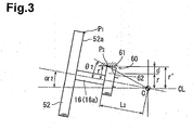
- Fig. 3 is a schematic view showing a second restriction surface of Fig. 1 in a state of contact with a first restriction surface;
- Fig. 4 is a longitudinal cross-sectional view showing a compressor according to a first embodiment of the present invention;
- Fig. 5 is an enlarged cross-sectional view showing the electromagnetic clutch of Fig. 4;
- Fig. 6 is an enlarged cross-sectional view showing a compressor according to a second embodiment;
- Fig. 7 is an enlarged cross-sectional view showing a compressor according to a third embodiment;
- Fig. 8 is an enlarged cross-sectional view showing a compressor according to a fourth embodiment; and
- Fig. 9 is an enlarged cross-sectional view showing a compressor according to a fifth embodiment.
- Figs. 1 to 5 show a first embodiment according to the present invention. In each drawing, the left is the front and the right is the rear.
- Figs. 4 and 5 show a compressor 1 according to the first embodiment. The compressor 1 is a variable displacement swash plate type compressor. CO2 is used as the refrigerant of the compressor 1. The compressor 1 is provided with a
housing 10, adrive shaft 16, acompression mechanism 20, and anelectromagnetic clutch 50. That is to say, the compressor 1 is a rotation apparatus having anelectromagnetic clutch 50. - The
housing 10 has a cylinder block 11, afront housing member 12, and arear housing member 14. Thefront housing member 12 is joined to the front end of the cylinder block 11. Therear housing member 14 is joined to the rear end of the cylinder block 11 with avalve assembly 13 in between. - A
crank chamber 15 is defined in thehousing 10. Thecrank chamber 15 is located between the cylinder block 11 and thefront housing member 12. Thedrive shaft 16 extends through thecrank chamber 15, the cylinder block 11, and thefront housing member 12. Arear bearing 81 supports thedrive shaft 16 so that thedrive shaft 16 is rotatable relative to the cylinder block 11. Afront bearing 82 supports thedrive shaft 16 so that thedrive shaft 16 is rotatable relative to thefront housing member 12. Therear bearing 81 and thefront bearing 82 are both radial bearings. Thefront housing member 12 contains afront seal 90 which is located in front of thefront bearing 82. Thefront seal 90 seals thedrive shaft 16 to thefront housing member 12. - A
boss 12a is formed in the front portion of thefront housing member 12. Thecylindrical boss 12a protrudes to the front along the axis CL of thedrive shaft 16. The front end (front end portion) of thedrive shaft 16 is referred to as a shaftfront end 16a. At least a portion of the shaftfront end 16a is located inside theboss 12a. The shaftfront end 16a protrudes to the front from thefront seal 90. Thefront seal 90 is a general oil seal. Thefront seal 90 has, for example, an annular body made of a metal and a lip made of rubber which is integrated with the annular body. That is to say, thefront seal 90 barely applies force for restraining the shaftfront end 16a, even when the shaftfront end 16a swings relative to the axis CL. Accordingly, the shaftfront end 16a is in such a state as to be supported by thefront bearing 82 like a cantilever. - The center point at the front end of the
front bearing 82 is referred to as a bearing front center C. That is to say, the shaftfront end 16a can swing in the direction perpendicular to the axis CL with the bearing front center C at a fixed point. In particular, since the refrigerant of the compressor 1 according to the present embodiment is CO2, thedrive shaft 16 tends to have a smaller diameter in comparison with compressors in which the refrigerant is, for example, a chlorofluorocarbon.gas. That is to say, thedrive shaft 16 according to the present embodiment has a lower rigidity, and thus, very easily swings in comparison with compressors in which the refrigerant is a chlorofluorocarbon gas. - An electromagnetic clutch 50 is switchable between a state where the drive force from an engine E, which functions as an external drive source, is transmitted to the
drive shaft 16 and a state where the drive force is disconnected from thedrive shaft 16. The engine E is a drive force supply for driving the vehicle. - The
electromagnetic clutch 50 has arotor 51, astator 56, anarmature 52, and ahub 53. - As shown in Figs. 4 and 5, the
rotor 51 is located outside and in front of thehousing 10. Therotor bearing 84 is a radial bearing which supports therotor 51 so that therotor 51 is rotatable relative to the outer peripheral surface of theboss 12a. Therotor 51 is operatively linked to the engine E via abelt 59. Afirst friction surface 51a is formed at the front end of therotor 51. Thestator 56 is secured to the front end of thefront housing member 12. Thestator 56 appears as if it were contained within therotor 51. Anelectromagnetic coil 56a is incorporated in thestator 56. The disc-shapedarmature 52 has an opening at the center. Asecond friction surface 52a is formed at the rear end of thearmature 52. Thesecond friction surface 52a is placed so as to face thefirst friction surface 51a. Thefirst friction surface 51a is an electric friction surface of therotor 51, and thesecond friction surface 52a is an electric friction surface of thearmature 52. Thehub 53 is cylindrical and has a flange at the front end. Thehub 53 has anengaging hole 53a for engaging the shaftfront end 16a at the center. Thearmature 52 is attached to thehub 53 by means of anelastic member 54 so as to be movable relative to thehub 53. As a result, thehub 53 links thearmature 52 to thedrive shaft 16. Theelastic member 54 is joined to the outer peripheral surface of thehub 53 and thearmature 52. - When the
electromagnetic coil 56a is energized, the magnetic force of thestator 56 attracts thearmature 52. Accordingly, thearmature 52 moves toward thestator 56 against the elastic force of theelastic member 54. Thesecond friction surface 52a makes contact with thefirst friction surface 51a. As a result, the drive force of the engine E is transmitted from therotor 51 to thearmature 52, thehub 53 and thedrive shaft 16. Accordingly, thearmature 52, thehub 53 and thedrive shaft 16 rotate together with therotor 51. - In contrast, when the
electromagnetic coil 56a is not energized, thestator 56 does not attract thearmature 52 as shown in Figs. 4 and 5. As a result, the elastic force of theelastic member 54 returns thearmature 52 to its original location. That is to say, thesecond friction surface 52a moves away from thefirst friction surface 51a. Accordingly, thearmature 52, thehub 53 and thedrive shaft 16 do not rotate together with therotor 51. Accordingly, the drive force of the engine E is not transmitted to thedrive shaft 16, and thus, thedrive shaft 16 stops. - Therefore, when the engine E operates, the
electromagnetic clutch 50 is controlled in accordance with the situation, and thus, switching is carried out so that the drive force of the engine E is either transmitted to thedrive shaft 16 or disconnected from thedrive shaft 16. As a result, thedrive shaft 16 rotates in an appropriate manner. - An annular
large diameter member 71 is engaged with the shaftfront end 16a, which is located inside theboss 12a. The diameter of the outer peripheral surface of thelarge diameter member 71 is greater than the diameter of the shaftfront end 16a. Thelarge diameter member 71 is originally a different member from thedrive shaft 16. As the material for thelarge diameter member 71, a metal material, such as iron or aluminum, a hard resin, such as a PPS resin (poly phenylene sulfide resin), or a general material, such as a compound material, or a combination of these may be used. The outer peripheral surface of thelarge diameter member 71 is afirst restriction surface 61. In other words, the outer peripheral portion of thedrive shaft 16 has thefirst restriction surface 61 in an integrated manner. Thelarge diameter member 71 is a large diameter portion of thedrive shaft 16 and formed so as to have a larger diameter. The first restriction surface 61a is the outer peripheral surface of the large diameter portion. - In addition, the inner peripheral surface of the
boss 12a is asecond restriction surface 62. That is to say, the inner peripheral portion of theboss 12a has thesecond restriction surface 62 in an integrated manner. Thesecond restriction surface 62 faces thefirst restriction surface 61 in the radial direction. - A case where, as shown in Figs. 4 and 5, the
electromagnetic coil 56a is not energized, that is to say, theelectromagnetic clutch 50 is in a disconnection state, is described. The radius of the outermost periphery of thesecond friction surface 52a (outermost armature periphery P1) with the axis CL at the center is referred to as a clutch radius R. The distance between thefirst friction surface 51a and thesecond friction surface 52a in the axial direction is referred to as a disconnection distance D. In general, the clutch radius R is approximately 40 mm to 60 mm, and the disconnection distance D is approximately 0.1 mm to 0.3 mm. - A
noise preventing space 60 is set between thefirst restriction surface 61 and thesecond restriction surface 62. The size d of thenoise preventing space 60 satisfies d < D × (L2)/R ... Formula (1) at a point that is spaced from the bearing front center C to the front by a beam size L2. For example, in the case where the clutch radius R = 60 mm, the disconnection distance D = 0.35 mm, and the beam size L2 = 40 mm, the space d < 0.2 mm. - Formula (1) is derived as follows in reference to Figs. 1 to 3. In Figs. 1 to 3, the left is the front and the right is the rear. As shown in Fig. 1, the
second friction surface 52a is located at a first distance L1 from the bearing front center C to the front. Thefirst friction surface 51a is located at a second distance L1' from the bearing front center C to the front (L1' < L1). - As shown in Fig. 1, the outermost periphery (outermost shaft periphery P2) at the front end of the
first restriction surface 61 is located at a beam size L2 from the bearing front center C to the front. The radius of the outermost shaft periphery P2 with the axis CL at the center is referred to as a first radius r. The radius of thesecond restriction surface 62 with the axis CL at the center is referred to as a second radius r' (r < r'). - A first line C-P1 which connects any given point in the outermost armature periphery P1 to the bearing front center C inclines at a first angle θ1 relative to the axis CL. A second line C-P2 which connects any given point in the outermost shaft periphery P2 to the bearing front center C inclines at a second angle θ2 relative to the axis CL.
- Next, a case where, as shown in Figs. 2 and 3, the shaft
front end 16a swings relative to the axis CL is described. Strictly speaking, the shaftfront end 16a is flexed so as to make a curve. However, the displacement of thedrive shaft 16 is microscopic, and therefore, it can be assumed that the shaftfront end 16a bends with the bearing front center C functioning as a bending point, and inclines in a straight line relative to the axis CL. - In the case where, as shown in Fig. 2, the
second friction surface 52a makes contact with thefirst friction surface 51a, that is to say, in the case where the outermost armature periphery P1 makes contact with therotor 51, the shaftfront end 16a inclines by a first inclination angle α1 relative to the axis CL. The relationship between the first inclination angle α1, the disconnection distance D and the clutch radius R is obtained as follows. Since the first inclination angle α1 is microscopic, the approximation formula of formula 2-5 is applied.


- The relational formula 2-9 representing the relationship between the first inclination angle α1, the disconnection distance D, and the clutch radius R is derived in this manner.
- In the case where, as shown in Fig. 3, the
first restriction surface 61 makes contact with thesecond restriction surface 62, that is to say, in the case where the outermost shaft periphery P2 makes contact with the inner peripheral portion of theboss 12a, the shaftfront end 16a inclines by a second inclination angle α2 relative to the axis CL. The relationship between the second inclination angle α2, the size d of thenoise preventing space 60 and the beam size L2 is obtained as follows. Since the second inclination angle α2 is microscopic, the approximation formula 3-5 is applied.


- The relational formula 3-9 representing the relationship between the second inclination angle α2, the size d of the
noise preventing space 60 and the beam size L2 is derived in this manner. - In order to prevent the
second friction surface 52a from making contact with thefirst friction surface 51a, it is necessary for thefirst restriction surface 61 to make contact with thesecond restriction surface 62. That is to say, in order to prevent the outermost armature periphery P1 from making contact with therotor 51, it is necessary for the outermost shaft periphery P2 to make contact with the inner peripheral surface of theboss 12a. Accordingly, it is necessary for the first inclination angle α1 and the second inclination angle α2 to satisfy the formula 4-1(α1 > α2). d < D × (L2)/R ... Formula (1) is gained by substituting the formula 2-9 and the formula 3-9 into the formula 4-1.


- As shown in Fig. 4, the rear end of the
hub 53 contacts and is stopped by thefront surface 71a of thelarge diameter member 71. Accordingly, thelarge diameter member 71 determines the depth of insertion of thehub 53 when thehub 53 is mounted at the shaftfront end 16a. That is to say, the depth of insertion of thehub 53 can be easily set, even in the case where it is difficult to provide a recess which is hit by and stops thehub 53 in athin drive shaft 16. - A
lug plate 17 and a swash plate 18 are placed inside thecrank chamber 15. Thelug plate 17 is attached to thedrive shaft 16 so that the two rotate integrally. Athrust bearing 83 is placed between thelug plate 17 and thefront housing member 12. The swash plate 18 is basically in disc-shaped, and the base of the swash plate 18 is made of an iron based material, such as spherical graphite cast iron (FCD) or bearing steel (SUJ2). A sliding layer is formed as the surface layer of the swash plate 18 (front surface and rear surface of swash plate 18) through thermal spray coating of, for example, a Cu-Sn-Pb based alloy or an Al-Si based alloy. Thecompression mechanism 20 is a swash plate type compression mechanism. - The center portion of the swash plate 18 has a through
hole 18a through which thedrive shaft 16 extends. Thedrive shaft 16 makes contact with the peripheral surface of the throughhole 18a, and thus, supports the swash plate 18 so that the swash plate 18 is slidable and inclinable. Ahinge mechanism 19 is placed between thelug plate 17 and the swash plate 18. - As shown in Fig. 4, the
hinge mechanism 19 includes twofirst protrusions 41 and onesecond protrusion 42. Thefirst protrusions 41 protrude to the rear from thelug plate 17. Thefirst protrusion 41 on the top in the drawing is omitted. Thesecond protrusion 42 protrudes to the front from the swash plate 18. Thefirst protrusions 41 are lug plate protrusions, and thesecond protrusion 42 is a swash plate protrusion. The end of thesecond protrusion 42 is located between the twofirst protrusions 41. Accordingly, the rotational force of thelug plate 17 is transmitted from thefirst protrusions 41 to thesecond protrusion 42, and thus, transmitted to the swash plate 18. - The
lug plate 17 has acam portion 43 which is located at the base of thefirst protrusions 41. Thecam portion 43 has acam surface 43a which faces the swash plate 18. The end of thesecond protrusion 42 slides on thecam surface 43a. Accordingly, thecam surface 43a guides the inclination of the swash plate 18. - The cylinder block 11 has the cylinder bores 22 placed at equal angular intervals around the axis CL of the
drive shaft 16. The respective cylinder bores 22 extend through the cylinder block 11 in the front-rear direction (left-right direction in the drawing). A one-head type piston 23 is contained in each cylinder bore 22. Thevalve assembly 13 closes the opening in the rear of the cylinder bores 22, and thepistons 23 close the opening in the front of the cylinder bores 22. As a result, a compression chamber 24 is defined in each cylinder bore 22. As thepistons 23 move, the volume of the compression chambers 24 changes. - Each
piston 23 has acolumnar head 37 and askirt 38 located in the front portion of thehead 37. Thehead 37 is inserted into the cylinder bore 22. Theskirt 38 is located in thecrank chamber 15 outside the cylinder bore 22. Thehead 37 and theskirt 38 are made of an aluminum based metal material. The aluminum based metal material includes at least either pure aluminum or an aluminum alloy. A pair ofshoe seats 38a are provided as recesses inside theskirt 38. A pair ofshoes 25 are contained inside theskirt 38. The pair ofshoes 25 are formed of afirst shoe 25A and asecond shoe 25B, each of which is in hemispherical form. Thesecond shoe 25B is located between thefirst shoe 25A and the compression chamber 24. Thesecond shoe 25B is more likely to receive compression reaction force in comparison with thefirst shoe 25A. The material for thefirst shoe 25A and thesecond shoe 25B is at least one of an iron based material, such as SUJ2, an aluminum based material, such as an aluminum alloy or an argil alloy, or an alloy of these. A surface treatment, such as Ni plating, may be carried out on the surface of thefirst shoe 25A and thesecond shoe 25B. In the present specification, "hemisphere" not only means a portion gained by dividing a sphere into two, but also includes a portion having a part of a spherical surface. - The
first shoe 25A and thesecond shoe 25B each have ahemispherical surface 25a and a flat slidingsurface 25b which is located on the side opposite to thehemispherical surface 25a. Eachspherical surface 25a is received by a spherical surface in thecorresponding shoe seat 38a. Thehemispherical surface 25a of thefirst shoe 25A and thehemispherical surface 25a of thesecond shoe 25B are on the same spherical surface. Eachpiston 23 is engaged and held in the outer peripheral portion of the swash plate 18 through thefirst shoe 25A and thesecond shoe 25B. The slidingsurface 25b of thefirst shoe 25A makes contact with the front surface of the swash plate 18. The slidingsurface 25b of thesecond shoe 25B makes contact with the rear surface of the swash plate 18. Accordingly, when the swash plate 18 rotates due to the rotation of thedrive shaft 16, thepistons 23 reciprocate linearly in the front-rear direction. - A
suction chamber 26 and adischarge chamber 27 are respectively defined between thevalve assembly 13 and therear housing member 14. Thevalve assembly 13 hassuction ports 28 andsuction valves 29 which are located between the respective compression chambers 24 and thesuction chamber 26, and furthermore, hasdischarge ports 30 anddischarge valves 31 which are located between the respective compression chambers 24 and thedischarge chamber 27. - The
lug plate 17, the swash plate 18, thehinge mechanism 19, thepistons 23, theshoes 25, the cylinder bores 22, thesuction ports 28, thesuction valves 29, thedischarge ports 30 and thedischarge valves 31 form thecompression mechanism 20. Thecompression mechanism 20 draws in, compresses, and afterwards, discharges refrigerant. Thecompression mechanism 20 is a rotation mechanism provided inside thehousing 10 of the compressor 1. Thecompression mechanism 20 is operable through rotation of thedrive shaft 16. - CO2 is used as the refrigerant for the refrigeration circuit. The refrigerant gas flows into the
suction chamber 26 from an external circuit (not shown). When therespective pistons 23 moves from the top dead center toward the bottom dead center, the refrigerant gas in thesuction chamber 26 passes through thesuction port 28 and thesuction valve 29 and is drawn into the compression chambers 24. When thepistons 23 move from the bottom dead center toward the top dead center, the refrigerant gas in the compression chambers 24 is compressed and passes through thedischarge port 30 and thedischarge valve 31 so as to be discharged into thedischarge chamber 27. The refrigerant gas flows out from thedischarge chamber 27 to the external circuit. - The
housing 10 has anair bleed passage 32, anair supply passage 33 and acontrol valve 34. Theair bleed passage 32 connects thecrank chamber 15 to thesuction chamber 26. Theair supply passage 33 connects thedischarge chamber 27 to the crankchamber 15. A publicly knowncontrol valve 34, for example an electromagnetic valve (schematically shown in Fig. 4), is placed in the middle of theair supply passage 33. - The external control on the power supply adjusts the degree of opening of the
control valve 34, and thus, the balance between the amount of high pressure discharge gas which is guided out and flows into thecrank chamber 15 through theair supply passage 33 and the amount of gas which is guided out and flows out from thecrank chamber 15 through theair bleed passage 32 is controlled, so that the pressure in thecrank chamber 15 is determined. As the pressure in thecrank chamber 15 changes, the difference in pressure between thecrank chamber 15 and the compression chambers 24 changes, so that the inclination angle of the swash plate 18 changes. Accordingly, the stroke of thepistons 23 is adjusted. That is to say, the displacement of thecompression mechanism 20 is adjusted. - When the degree of opening of the
control valve 34 is decreased, the pressure in thecrank chamber 15 lowers. Therefore, the inclination angle of the swash plate 18 increases, the stroke of thepistons 23 increases, and the displacement of thecompression mechanism 20 increases. In contrast, when the degree of opening of thecontrol valve 34 is increased, the pressure in thecrank chamber 15 rises. Therefore, the inclination angle of the swash plate 18 decreases, the stroke of thepistons 23 decreases, and the displacement of thecompression mechanism 20 decreases. - The compressor 1 and the external circuit form a vehicle refrigeration circuit and air-conditions the inside of the vehicle.
- The first embodiment has the following advantages.
- (1) The size d of the
noise preventing space 60 satisfies d < D x (L2)/R ... Formula (1). - When the electromagnetic clutch 50 disconnects the drive force of the engine E from the
drive shaft 16 in a state where the engine E is driven, thearmature 52, thehub 53 and thedrive shaft 16 stop while therotor 51 keeps rotating. When vibration and impact of the vehicle in which the compressor 1 is mounted are transmitted to the compressor 1, thearmature 52, thehub 53, and thedrive shaft 16 also vibrate. - In the present embodiment, when the amount of fluctuation of the vibrating shaft
front end 16a increases, thefirst restriction surface 61 makes contact with thesecond restriction surface 62. Accordingly, the inclination angle of thedrive shaft 16 is kept from increasing. As a result, thesecond friction surface 52a is prevented from unnecessarily becoming of such a state as to make contact with thefirst friction surface 51a. Therefore, a state where therotor 51 in a rotating state and thearmature 52 in a stationary state make contact with a great difference in the relative speed is prevented. - Accordingly, abnormal noises coming from the electromagnetic clutch 50 are suppressed. As a result, passengers inside the vehicle barely feel any discomfort due to abnormal noises.
- (2) The
first restriction surface 61 is the outer peripheral surface of thelarge diameter member 71, which is a separate body mounted on thedrive shaft 16. Therefore, even in the case where an already existingdrive shaft 16 is used, the present invention is easily implemented, and the costs of manufacture are reduced. - (3) The rotation apparatus is a
compression mechanism 20 which draws in, compresses, and afterward, discharges CO2, which functions as a refrigerant. In the case where CO2 is the refrigerant, the pressure of the compressed refrigerant has a very high value of approximately 15 MPa. Accordingly, high sealing performance is required in thefront seal 90 between thedrive shaft 16 and thehousing 10. The smaller the diameter of the sealed portion of thedrive shaft 16 is, the easier it is to secure sealing performance between thehousing 10 and thedrive shaft 16. Therefore, the diameter of the sealed portion of thedrive shaft 16 and the diameter of the shaftfront end 16a tend to be set small. That is to say, the rigidity of thedrive shaft 16 is low and the front end of thedrive shaft 16 easily swings. Accordingly, the present embodiment has further significant effects in the present invention.
Fig. 6 shows a second embodiment of the present invention. As shown in Fig. 6, a compressor according to the second embodiment has alarge diameter portion 72 formed in thehub 53. Thelarge diameter member 71 is omitted. A bufferingmember 12b is provided on the inner peripheral surface of theboss 12a. Like or the same reference numerals are given to those components that are like or the same as those in the compressor 1 according to the first embodiment, and detailed explanations are omitted.
Thelarge diameter portion 72 is a flange which protrudes outward from thehub 53 made of a metal in the radial direction. Thelarge diameter portion 72 is inside theboss 12a. The outer peripheral surface of thelarge diameter portion 72 is afirst restriction surface 61b. That is to say, the outer peripheral portion of thehub 53 has afirst restriction surface 61b in an integrated manner. In other words, part of the outer peripheral surface of thehub 53 is made greater, so that thelarge diameter portion 72 is formed integrally with thehub 53. Thefirst restriction surface 61b can be assumed to be an outer peripheral surface of thehub 53.
The bufferingmember 12b is made of a PDS resin and is cylindrical, and is engaged with the inner peripheral surface of theboss 12a. The inner peripheral surface of the bufferingmember 12b is asecond restriction surface 62b. That is to say, the inner peripheral portion of theboss 12a has asecond restriction surface 62b in an integrated manner. Thesecond restriction surface 62b faces thefirst restriction surface 61b in the radial direction.
Anoise preventing space 60b is provided between thefirst restriction surface 61b and thesecond restriction surface 62b. The size d of thenoise preventing space 60b satisfies d < D × (L2)/R ... Formula (1) at a point that is spaced by the distance corresponding to the beam size L2 from the bearing front center C to the front.
The second embodiment has the same advantages as the first embodiment, and in addition, has the following advantages. - (4) The
first restriction surface 61b is an outer peripheral surface of thelarge diameter portion 72 formed in thehub 53. Therefore, the configuration of the present invention is easy to implement. That is to say, the costs of manufacture are reduced. - (5) A
buffering member 12b is provided on thesecond restriction surface 62b. The bufferingmember 12b is a buffering layer for buffering collision of thefirst restriction surface 61b against thesecond restriction surface 62b. Therefore, even small abnormal noises can be suppressed when thefirst restriction surface 61b makes contact with thesecond restriction surface 62b in such a state that there is no difference in the relative speed.
Fig. 7 shows a third embodiment of the present invention. As shown in Fig. 7, the compressor according to the third embodiment has asmall diameter member 73 provided in theboss 12a.
The outer peripheral surface of thedrive shaft 16 forms afirst restriction surface 61c according to the third embodiment. That is to say, the outer peripheral portion of thedrive shaft 16 has afirst restriction surface 61c in an integrated manner.
The annularsmall diameter member 73 which is a separate member from theboss 12a is engaged with the inner peripheral surface of theboss 12a. The material for thesmall diameter member 73 is the same as that for thelarge diameter member 71. The inner peripheral surface of thesmall diameter member 73 is asecond restriction surface 62c. That is to say, the inner peripheral portion of theboss 12a has asecond restriction surface 62c in an integrated manner. Thesecond restriction surface 62c faces thefirst restriction surface 61c in the radial direction.
Anoise preventing space 60c is provided between thefirst restriction surface 61c and thesecond restriction surface 62c. The size d of thenoise preventing space 60c satisfies d < D × (L2) /R ... Formula (1) at a point spaced by the distance corresponding to the beam size L2 from the bearing front center C to the front.
The third embodiment has the following additional advantages. - (6) The
second restriction surface 62c is an inner peripheral surface of thesmall diameter member 73 secured to theboss 12a. Accordingly, the configuration of the present invention is easy to implement. As a result, the costs of manufacture are reduced.
Fig. 8 shows a fourth embodiment of the present invention. The compressor according to the fourth embodiment has amechanical seal 91 instead of thefront seal 90.
As shown in Fig. 8, the diameter of thefront bearing 82a in the fourth embodiment is much greater than that of thefront bearing 82 in the first embodiment. As a result, themechanical seal 91 can be mounted on thedrive shaft 16, despite being greater than thefront seal 90. Thelug plate 17 has acylindrical portion 17a which protrudes to the front so as to cover thedrive shaft 16. Thefront bearing 82a supports thedrive shaft 16 and thecylindrical portion 17a so that thedrive shaft 16 and thecylindrical portion 17a are rotatable relative to thefront housing member 12.
Themechanical seal 91 has a fixedring 92, arotational ring 93, agasket 94, aspring 95, and aseal case 96. The fixedring 92 is secured to the inner peripheral surface of ashaft hole 12c. The rear end of the fixedring 92 has a fixedseal end surface 92a. Theseal case 96 is attached to thedrive shaft 16. Theseal case 96 contains therotational ring 93 and thespring 95. Therotational ring 93 is a movable ring which is attached to thedrive shaft 16 inside thehousing 10. The front end of therotational ring 93 has a rotationalseal end surface 93a which slides against the fixedseal end surface 92a. Thegasket 94 is attached to thedrive shaft 16 on the rear surface of therotational ring 93. Theannular gasket 94 seals the space between therotational ring 93 and thedrive shaft 16. Thespring 95 is attached to theseal case 96. Thespring 95 presses therotational ring 93 against the fixedring 92.
That is to say, thespring 95 presses the rotationalseal end surface 93a against the fixedseal end surface 92a. Therefore, the high pressure refrigerant, for example CO2, can be prevented from passing through the gap between theshaft hole 12c and thedrive shaft 16 and leaking out. Themechanical seal 91 reliably seals the gap.
The outer peripheral surface of thedrive shaft 16 forms thefirst restriction surface 61d according to the fourth embodiment. That is to say, the outer peripheral portion of thedrive shaft 16 has afirst restriction surface 61d in an integrated manner.
The inner peripheral surface of the fixedring 92 forms asecond restriction surface 62d. That is to say, the inner peripheral portion of theboss 12a has asecond restriction surface 62d in an integrated manner. Thesecond restriction surface 62d faces the first-restriction surface 61d in the radial direction.
Anoise preventing space 60d is provided between thefirst restriction surface 61d and thesecond restriction surface 62d. The size d of thenoise preventing space 60d satisfies d < D × (L2)/R ... Formula (1) at a point spaced by the distance corresponding to a beam size L2 from the center of the front end of thefront bearing 82a (bearing front center C) to the front. The distance between theseal case 96 and the inner peripheral surface of theshaft hole 12c is set larger than thenoise preventing space 60d. That is to say, the distance between the outer peripheral surface of therotational ring 93 and the inner peripheral surface of theshaft hole 12c is larger than thenoise preventing space 60d. In addition, the distance between thespring 95 and the inner peripheral surface of theshaft hole 12c is greater than thenoise preventing space 60d.
The fourth embodiment has the following additional advantage. - (7) The fixed
ring 92 in themechanical seal 91 is used as the small diameter member. Therefore, it is not necessary to separately prepare a small diameter member for the compressor. That is to say, the costs of manufacture are reduced.
Fig. 9 shows a fifth embodiment of the present invention. The compressor according to the fifth embodiment also has amechanical seal 91. Therotational ring 93 of themechanical seal 91 functions as the large diameter member.
As shown in Fig. 9, thefirst restriction surface 61e is the front portion of the outer peripheral surface of therotational ring 93. That is to say, the outer peripheral portion of thedrive shaft 16 has afirst restriction surface 61e in an integrated manner. Thesecond restriction surface 62e is an inner peripheral surface of theshaft hole 12c. That is to say, the inner peripheral portion of theboss 12a has asecond restriction surface 62e in an integrated manner. Thesecond restriction surface 62e faces thefirst restriction surface 61e in the radial direction.
A noise preventing space 60e is provided between thefirst restriction surface 61e and thesecond restriction surface 62e. The size d of the noise preventing space 60e satisfies d < D × (L2)/R ... Formula (1) at a point spaced by the distance corresponding to the beam size L2 from the bearing front center C to the front. The distance between the outer peripheral surface of thedrive shaft 16 and the inner peripheral surface of the fixedring 92 is set larger than the noise preventing space 60e.
The fifth embodiment has the following additional advantages. - (8) The
rotational ring 93 of themechanical seal 91 is used as the large diameter member. Therefore, it is not necessary to separately prepare a large diameter member for the compressor. That is to say, the costs of manufacture are reduced. - The first to fifth embodiments may be modified as follows.
- In the first embodiment shown in Fig. 5, it is not necessary to mount a
large diameter member 71 separated from thedrive shaft 16 on thedrive shaft 16.. Part of thedrive shaft 16 may have a large diameter, for example, and thus, a large diameter portion may be formed integrally with the drive shaft. Thus, thefirst restriction surface 61 may be an outer peripheral surface of a large diameter portion provided around thedrive shaft 16. - In the third embodiment shown in Fig. 7, it is not necessary to mount a
small diameter member 73 separated from theboss 12a on theboss 12a. Part of theboss 12a may have a small diameter, for example, and thus, a small diameter portion may be formed integrally with theboss 12a. That is to say, thesecond restriction surface 62c may be an inner peripheral surface of a small diameter portion provided in theboss 12a. - In the second embodiment shown in Fig. 6, it is not necessary for the
buffering member 12b to be made of a PPS resin. The bufferingmember 12b may be formed by pasting a general buffering material, such as rubber, an elastomer, a soft resin, a hard resin or a metal, to the inner peripheral surface of theboss 12a. In addition, the bufferingmember 12b may be formed by coating the inner peripheral surface of theboss 12a with one of these materials. - In addition, the buffering layer, for example, the buffering
member 12b, may be provided on at least either the first restriction surface 61-61e or the second restriction surface 62-62e. - The outer peripheral portion of a drive shaft (16) has a first restriction surface (61) in an integrated manner. The inner peripheral portion of a boss (12a) has a second restriction surface (62) in an integrated manner. The second restriction surface (62) faces the first restriction surface (61) in a radial direction. When the electromagnetic coil (56a) is not energized, there is a disconnection distance D between the first friction surface (51a) and the second friction surface (52a). The distance between the axis (CL) and the outermost periphery (P1) of the second friction surface (52a) is the clutch radius R. A noise preventing space (60) is provided at a point spaced from the bearing (82) to the front by a beam size L2 between the first restriction surface (61) and the second restriction surface (62). The size d of the noise preventing space (60) satisfies d < D × (L2)/R. Accordingly, abnormal noises coming from the electromagnetic clutch (50) are suppressed (Fig. 4).
Claims (8)
- A rotation apparatus (1) driven by an external drive source (E), the rotation apparatus (1) comprising:a housing (10);a drive shaft (16) extending in a front-rear direction, a front portion of the housing (10) having a boss (12a) protruding to the front, the boss (12a) being cylindrical with an axis (CL) of the drive shaft (16) at the center, and at least a portion of a front end (16a) of the drive shaft (16) being located inside the boss (12a);a bearing (82,82a) for supporting the drive shaft (16) so that the drive shaft (16) is rotatable relative to the housing (10);a seal (90,91) placed inside the housing (10), the shaft front end (16a) protruding to the front from the seal (90,91), and the seal (90,91) sealing the drive shaft (16) in front of the bearing (82,82a);a rotation mechanism (20) provided inside the housing (10), the rotation mechanism (20) being operable through rotation of the drive shaft (16); andan electromagnetic clutch (50) which is switchable between a state where the drive force is transmitted from the external drive source (E) to the drive shaft (16) and a state where the drive force is disconnected from the drive shaft (16),wherein the electromagnetic clutch (50) has:a rotor (51) supported by the boss (12a) so as to be rotatable, the rotor (51) being operatively linked to the external drive source (E) and the rotor (51) having a first friction surface (51a) which faces the front;a stator (56) contained in the rotor (51), an electromagnetic coil (56a) being incorporated in the stator (56);a disc-shaped armature (52), the armature (52) having a second friction surface (52a) facing the rear, and the second friction surface (52a) facing the first friction surface (51a); anda hub (53) for linking the armature (52) to the drive shaft (16),the rotation apparatus being characterized in thatan outer peripheral portion of the drive shaft (16) or an outer peripheral portion of the hub (53) has a first restriction surface (61, 61b, 61c, 61d, 61e) in an integrated manner, an inner peripheral portion of the boss (12a) has a second restriction surface (62, 62b, 62c, 62d, 62e) in an integrated manner, the second restriction surface (62-62e) facing the first restriction surface (61-61e) in a radial direction,wherein, when the electromagnetic coil (56a) is not energized, there is a disconnection distance D between the first friction surface (51a) and the second friction surface (52a) in the axial direction,
wherein the distance between the axis (CL) and an outermost periphery (P1) of the second friction surface (52a) is a clutch radius R,
wherein a noise preventing space (60, 60b, 60c, 60d, 60e) is provided at a point spaced by a distance corresponding to a beam size L2 from the bearing (82,82a) to the front between the first restriction surface (61-61e) and the second restriction surface (62-62e), and
wherein the size d of the noise preventing space (60-60e) satisfies d < D × (L2)/R. - The rotation apparatus (1) according to claim 1, characterized by an annular large diameter member (71,93) provided around the drive shaft (16), the diameter of an outer peripheral surface of the large diameter member (71,93) being greater than the diameter of the drive shaft (16),
wherein the first restriction surface (61,61e) is the outer peripheral surface of the large diameter member (71,93). - The rotation apparatus (1) according to claim 2, characterized in that the seal (91) is a mechanical seal (91), the mechanical seal (91) having a fixed ring (92) and a movable ring (93) which slides against the fixed ring (92), the fixed ring (92) being provided in the housing (10), and the movable ring (93) being provided around the drive shaft (16), and
wherein the large diameter member (93) is the movable ring (93). - The rotation apparatus (1) according to claim 1, characterized in that the first restriction surface (61b) is an outer peripheral surface of the hub (53).
- The rotation apparatus (1) according to claim 1, characterized by:an annular small diameter member (73, 92) provided in the boss (12a), the diameter of an inner peripheral surface of the small diameter member (73, 92) being smaller than the diameter of the inner peripheral surface of the boss (12a),wherein the second restriction surface (62c, 62d) is the inner peripheral surface of the small diameter member (73, 92).
- The rotation apparatus (1) according to claim 5, characterized in that the seal (91) is a mechanical seal (91), the mechanical seal (91) having a fixed ring (92) and a movable ring (93) which slides against the fixed ring (92), the fixed ring (92) being provided in the housing (10), and the movable ring (93) being provided around the drive shaft (16), and
wherein the small diameter member (92) is the fixed ring (92). - The rotation apparatus (1) according to any of claims 1 to 6, characterized in that the rotation mechanism (20) is a compression mechanism (20), and the compression mechanism (20) draws in, compresses, and afterward, discharges CO2 which functions as a refrigerant.
- The rotation apparatus (1) according to claim 7, characterized by:a buffering layer (12b) provided on at least either the first restriction surface (61-61e) or the second restriction surface (62-62e),wherein the buffering layer (12b) buffers collision of the first restriction surface (61-61e) against the second restriction surface (62-62e).
Applications Claiming Priority (1)
| Application Number | Priority Date | Filing Date | Title |
|---|---|---|---|
| JP2006238021A JP2008057497A (en) | 2006-09-01 | 2006-09-01 | Rotating device with electromagnetic clutch |
Publications (1)
| Publication Number | Publication Date |
|---|---|
| EP1895159A2 true EP1895159A2 (en) | 2008-03-05 |
Family
ID=38556306
Family Applications (1)
| Application Number | Title | Priority Date | Filing Date |
|---|---|---|---|
| EP07115295A Withdrawn EP1895159A2 (en) | 2006-09-01 | 2007-08-30 | Rotation apparatus having electromagnetic clutch |
Country Status (3)
| Country | Link |
|---|---|
| US (1) | US20080053782A1 (en) |
| EP (1) | EP1895159A2 (en) |
| JP (1) | JP2008057497A (en) |
Family Cites Families (5)
| Publication number | Priority date | Publication date | Assignee | Title |
|---|---|---|---|---|
| US3719260A (en) * | 1971-12-27 | 1973-03-06 | Gen Motors Corp | Electromagnetic clutch |
| US5528976A (en) * | 1993-11-24 | 1996-06-25 | Kabushiki Kaisha Toyoda Jidoshokki Seisakusho | Swash plate type compressor with bearing assembly |
| JPH08144945A (en) * | 1994-11-22 | 1996-06-04 | Toyota Autom Loom Works Ltd | Double head cam plate type compressor |
| US6112639A (en) * | 1995-12-18 | 2000-09-05 | Kabushiki Kaisha Toyoda Jidoshokki Seisakusho | Structure for collecting leaking oil in compressor |
| JP4075129B2 (en) * | 1998-04-16 | 2008-04-16 | 株式会社豊田自動織機 | Control method of cooling device |
-
2006
- 2006-09-01 JP JP2006238021A patent/JP2008057497A/en active Pending
-
2007
- 2007-08-29 US US11/897,395 patent/US20080053782A1/en not_active Abandoned
- 2007-08-30 EP EP07115295A patent/EP1895159A2/en not_active Withdrawn
Also Published As
| Publication number | Publication date |
|---|---|
| US20080053782A1 (en) | 2008-03-06 |
| JP2008057497A (en) | 2008-03-13 |
Similar Documents
| Publication | Publication Date | Title |
|---|---|---|
| KR100274497B1 (en) | compressor | |
| US20030089223A1 (en) | Sliding member and sliding device | |
| US20090107327A1 (en) | Capacity-variable type swash plate compressor | |
| US6336795B1 (en) | Fluid displacement apparatus with suction reed valve stopper | |
| US20040131475A1 (en) | Shaft seal, compressor having the same and method for sealing shaft | |
| JP2000055223A (en) | Differential pressure control valve and compressor | |
| US20080053782A1 (en) | Rotation apparatus having electromagnetic clutch | |
| JP3985507B2 (en) | Swash plate compressor | |
| US6508633B2 (en) | Swash plate type compressor of variable capacity type | |
| JP3956726B2 (en) | Hermetic scroll compressor and its application equipment | |
| JP4120154B2 (en) | Piston compressor and assembly method thereof | |
| JP3615609B2 (en) | Swash plate compressor | |
| EP1918582A2 (en) | Bearing structure in rotating machine | |
| JP2005105975A (en) | Valve structure of compressor | |
| JP3609237B2 (en) | Swash plate type variable capacity compressor | |
| KR100614023B1 (en) | Variable displacement compressor | |
| JP4728097B2 (en) | Compressor | |
| JP4128656B2 (en) | Swash plate compressor | |
| US6912948B2 (en) | Swash plate compressor | |
| WO2007029481A1 (en) | Vane compressor | |
| JP2010007588A (en) | Refrigerant compressor | |
| KR100728412B1 (en) | Double Row Ball Bearing for Pulley Support | |
| JP2005188328A (en) | Piston type compressor | |
| WO2005124152A1 (en) | Seal structure of compressor | |
| KR100903060B1 (en) | Shaft Support Structure of Swash Plate Compressor |
Legal Events
| Date | Code | Title | Description |
|---|---|---|---|
| PUAI | Public reference made under article 153(3) epc to a published international application that has entered the european phase |
Free format text: ORIGINAL CODE: 0009012 |
|
| 17P | Request for examination filed |
Effective date: 20070830 |
|
| AK | Designated contracting states |
Kind code of ref document: A2 Designated state(s): AT BE BG CH CY CZ DE DK EE ES FI FR GB GR HU IE IS IT LI LT LU LV MC MT NL PL PT RO SE SI SK TR |
|
| AX | Request for extension of the european patent |
Extension state: AL BA HR MK YU |
|
| STAA | Information on the status of an ep patent application or granted ep patent |
Free format text: STATUS: THE APPLICATION HAS BEEN WITHDRAWN |
|
| 18W | Application withdrawn |
Effective date: 20090826 |
|
| R18W | Application withdrawn (corrected) |
Effective date: 20090824 |