EP1894869A2 - Sheet material inverter - Google Patents
Sheet material inverter Download PDFInfo
- Publication number
- EP1894869A2 EP1894869A2 EP07016576A EP07016576A EP1894869A2 EP 1894869 A2 EP1894869 A2 EP 1894869A2 EP 07016576 A EP07016576 A EP 07016576A EP 07016576 A EP07016576 A EP 07016576A EP 1894869 A2 EP1894869 A2 EP 1894869A2
- Authority
- EP
- European Patent Office
- Prior art keywords
- cage assembly
- sheet material
- input
- output
- bevel gear
- Prior art date
- Legal status (The legal status is an assumption and is not a legal conclusion. Google has not performed a legal analysis and makes no representation as to the accuracy of the status listed.)
- Granted
Links
Images



Classifications
-
- B—PERFORMING OPERATIONS; TRANSPORTING
- B65—CONVEYING; PACKING; STORING; HANDLING THIN OR FILAMENTARY MATERIAL
- B65H—HANDLING THIN OR FILAMENTARY MATERIAL, e.g. SHEETS, WEBS, CABLES
- B65H5/00—Feeding articles separated from piles; Feeding articles to machines
- B65H5/06—Feeding articles separated from piles; Feeding articles to machines by rollers or balls, e.g. between rollers
- B65H5/062—Feeding articles separated from piles; Feeding articles to machines by rollers or balls, e.g. between rollers between rollers or balls
-
- B—PERFORMING OPERATIONS; TRANSPORTING
- B65—CONVEYING; PACKING; STORING; HANDLING THIN OR FILAMENTARY MATERIAL
- B65H—HANDLING THIN OR FILAMENTARY MATERIAL, e.g. SHEETS, WEBS, CABLES
- B65H15/00—Overturning articles
- B65H15/016—Overturning articles employing rotary or reciprocating elements supporting transport means
-
- B—PERFORMING OPERATIONS; TRANSPORTING
- B65—CONVEYING; PACKING; STORING; HANDLING THIN OR FILAMENTARY MATERIAL
- B65H—HANDLING THIN OR FILAMENTARY MATERIAL, e.g. SHEETS, WEBS, CABLES
- B65H2301/00—Handling processes for sheets or webs
- B65H2301/30—Orientation, displacement, position of the handled material
- B65H2301/33—Modifying, selecting, changing orientation
- B65H2301/332—Turning, overturning
- B65H2301/3322—Turning, overturning according to a determined angle
- B65H2301/33224—180°
Definitions
- This invention relates to apparatus for inverting the orientation of sheet material and, more particularly, to a new and useful apparatus and system for inverting sheet material or a stack/collation thereof for use in sheet material handling equipment such as mailpiece fabrication systems.
- Sheet material handling systems frequently require sheet material or assembled collations thereof to be turned over to match a specific downstream requirement.
- mailpiece fabrication equipment typically requires that sheet material be oriented face-up or face down depending upon the orientation of a receiving envelope This requirement has come under increasing demand as new and old equipment have, over the course of time, been merged. That is, some mailpiece fabrication systems require a face-up orientation while others employ a face-down presentation. Effective utilization and coordination of all systems/machines becomes inefficient when specific mailpiece fabrication jobs can only be processed on specific machines.
- twist modules wherein sheets of material are directed linearly along a spiral path typically effected by a series of twisted belts or chords. While such twist modules retain the respective leading and trailing edge position of the sheet material, such modules require a lengthy axial path to change the face-up/ face-down orientation of the sheet material. Furthermore, twist modules are less reliable when handling stacked collations inasmuch as the stacked sheets tend to skew as they follow the spiral path. Moreover, such twist modules are not reconfigurable to handle straight runs wherein sheet material inversion is not required. Consequently, another module must be introduced in place of the twist module to reconfigure the sheet material handling equipment.
- Figure 1 is a partially broken away perspective view of a mailpiece fabrication device or mailpiece inserter including a sheet material inverter in accordance with the teachings of the present invention.
- Figure 2 is an isolated perspective of the sheet material inverter including a cage assembly, a torque drive mechanism for driving the cage assembly about a rotational axis, and a sheet conveyance mechanism for accepting and ejecting sheet material therefrom.
- Figure 3 is a broken-away cross-sectional view taken substantially along line 3 - 3 of Fig. 2 illustrating a bevel gear arrangement for driving the sheet conveyance mechanism.
- Figure 4 is a partially broken-away cross-sectional view taken substantially along line 4 - 4 of Fig. 2 illustrating a front view of the bevel gear arrangement for driving the sheet conveyance mechanism.
- Figure 5a is a cross-sectional view taken substantially along line 5a - 5a of Fig. 1 illustrating the cage assembly in an input position as sheet material is loaded by the sheet conveyance mechanism from an upstream transport module.
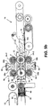
- Figure 5b is a cross-sectional view taken substantially along line 5a - 5a of Fig. 1 illustrating the cage assembly in an output position as sheet material is ejected by the sheet conveyance mechanism to a downstream transport module.
- Figs. 6a, 6b and 6c are simplified schematic views, shown in partial perspective, of the inverter operation as the cage assembly rotates and the sheet conveyance mechanism retards movement of the sheet material while being rotated from the input to output position.
- An apparatus for inverting the spatial orientation of sheet material from a desired input to a desired output orientation.
- the apparatus includes a cage assembly, a torque drive mechanism operative to rotate the cage assembly about a rotational axis and a sheet conveyance mechanism mounting to the cage assembly for conveying sheet material along the rotational axis of the cage assembly.
- the torque drive mechanism is adapted to assume input and output positions about the rotational axis wherein each position corresponds to the desired input and output orientations of the sheet material.
- the sheet conveyance mechanism is, furthermore, adapted to:
- FIG. 1 a perspective view is provided of an inventive sheet inversion apparatus 10 shown in combination with upstream and downstream sheet handling modules 12 and 14, respectively.
- the upstream and downstream modules are referred to as "Gates" on a typical multistation buffer with sheet material 16 traveling from left to right (in the direction of arrow FP indicative of the material feed path).
- sheet material means individual sheets or a mufti-sheet stack of material and, additionally, may include sheets fabricated from any of a variety of material compositions including paper, cardboard, fiber-reinforced composites, thermoplastics, open/closed reticulated foam, etc. Consequently, the terms “sheet material” and “stacked collations” may be used interchangeably herein.
- the sheet material 16 exits the upstream gate or module 12 and enters the sheet inverter 10 according to the present invention. While the sheet material 16 will, in the most common or conventional handling operation be "inverted” to "flip" the face sheets from face-up to face-down and visa-versa, it should be appreciated that the sheet material inverter 10 of the present invention may perform multiple operations. For example, the inverter 10 may convey the sheet material 16 to the downstream gate or module 14 without altering its orientation or may change the orientation of the sheet material 16 from a first to a second angular position.
- the sheet inverter 10 may accommodate any angular change within a full revolution or three-hundred and sixty degrees (360°) - albeit, the most common will generally be in multiples of ninety degrees (90°).
- the real estate occupied by the sheet inverter 10 is minimized. More specifically, the inverter 10 performs the spatial reorientation of the sheet material 16 in a minimal space envelope.
- the inverter 10 includes a cage assembly 20, a torque drive mechanism 40 and a sheet conveyance mechanism 50.
- the cage assembly 20 serves as a structural housing for the sheet conveyance mechanism 50 and assumes the input and output positions corresponding to the desired input and output orientation of the sheet material (not shown in Fig. 2).
- the cage assembly 20 is adapted to rotate about an axis RA which is also aligned with the feed path FP traveled by the sheet material as it passes from the upstream to downstream modules 12, 14 (see Fig. 1). Moreover, the cage assembly 20 defines a central bifurcating plane 20CP which is aligned with the rotational axis RA and bisects the cage assembly 20 symmetrically about a horizontal plane. The geometric significance of these relationships will become apparent/useful when describing the various interconnecting elements and components.
- the torque drive mechanism 40 is affixed to the cage assembly 20 and is operative to drive the cage assembly 20 about the rotational axis RA. While the torque drive mechanism 40 may include various drive belts and braking apparatus (not shown in Fig. 2) to accelerate, decelerate and stop the cage assembly 20, the only description required at this juncture relates to its principle function of driving torque to the cage assembly 20.
- the sheet conveyance mechanism 50 mounts internally of the cage assembly 20 and is operative to convey sheet material 16 along the rotational axis RA of the cage assembly 20.
- the sheet conveyance mechanism 50 is adapted to: (i) receive sheet material 16 when the cage assembly 20 is in the input position (e.g., when the cage assembly 20 is disposed at an initial zero degree (0°) orientation), (ii) eject sheet material 16 when the cage assembly 20 is in an output position (e.g., when the cage assembly 20 is disposed at a final one-hundred and eighty degree (180°) orientation), and (iii) temporarily pause/retard the movement of the sheet material 16 in response to rotation of the cage assembly 20 by the torque drive mechanism 40.
- the cage assembly 20 includes a central box structure 22, structural side supports 24, and a plurality at cross-members 26 structurally interconnecting the box structure 22 with the side supports 24.
- the central box structure 22 includes a base 22B which is orthogonal to the rotational axis RA at the cage assembly 20, a first pair of sidewall structures 22VS substantially parallel to the structural side supports 24 and a second pair of sidewall structures 22HS substantially parallel to the central bifurcating plane 20CP.
- the base 22B includes a central aperture 28 for receiving a through shaft of the sheet conveyance mechanism 50.
- first pair of sidewall structures 22VS includes apertures 30 and bushing supports 32 for supporting a plurality of drive shafts/axles of the sheet conveyance mechanism 50.
- the function of the various shafts/axles will become apparent when discussing the sheet conveyance mechanism 50 in greater detail.
- the cross-members 26 define inlet and outlet guides 34I 1 , 34I 2 , 34O 1 and 34O 2 (shown in Figs. 2 and 4) or accepting and ejecting sheet material (not shown) there through. More specifically, pairs of cross-members 260 define a gap therebetween for guiding sheet material there through when the sheet conveyance mechanism ejects sheet material.
- the perspective view shown in Fig. 2 provides a full view of the outlet guides 34O 1 , 34O 2 , defined by and between cross-members 260. While not shown in the perspective view, it should be appreciated that the cross-members 261 are configured in identical fashion to define first and second inlet guides 34I 1 and 34I 2 .
- first and second central cross-members 26C 1 , 26C 2 function to provide a pivot bearing support for pairs at idler rollers of the sheet conveyance mechanism 50.
- a single cross-member 26C 1 or 26C 2 is employed to center and support pairs of bell cranks, though it should be appreciated that other configurations may be adapted to support the idler rollers.
- the torque drive mechanism 40 is affixed to the cage assembly 20 for driving the same about its rotational axis RA.
- a splined pulley 42 is formed in combination with a drive shaft 44 (see Fig. 3) which connects to the base 22B of the cage assembly central box structure 22.
- a belt (not shown) defining a plurality of teeth engages the splined pulley 42 and rotates the cage assembly 20 from an input position (e.g., 0 degrees) to an output position (e.g., 180 degrees).
- a torque drive motor 44 receives input command.signals IC from sensors indicating when sheet material 16 has passed certain critical locations along the feed path. More specifically, photocells (not shown) may be disposed along or proximal to the terminal edges of the upstream and downstream modules 12, 14 to monitor or sense the passage of the sheet material leading and trailing edges. As the trailing edge passes a photocell, the input command signals IC may be issued to the torque drive motor 44 to initiate or terminate the rotary drive motor at a particular rotary position.
- a rotary encoder (not shown) may also be employed to determine the precise position of the cage assembly 20 relative to fixed reference points/locations.
- a caliper brake (not shown) may also be employed to decelerate and/or stop the cage assembly at a fixed reference position (i.e., input or output position).
- the sheet conveyance mechanism 50 mounts to the cage assembly 20 and includes rolling elements 52, 54 for capturing sheet material therebetween and a bevel gear arrangement 60 for driving at least one of the rolling elements 54.
- Each of the rolling elements 52, 54 rotates about axes 52A orthogonal to the rotational axis RA of the cage assembly 20.
- sixteen (16) rolling elements 52, 54 define four (4) sets of control nips S1, S2, S3 and S4 wherein two (2) sets S1, S2 are disposed along an upper deck of the cage assembly 20 (to one side of the central bifurcating plane 20CP) and another two (2) sets S3, S4 are disposed along a lower deck of the cage assembly 20 (to the other side of the central bifurcating plane 20CP).
- sheet material 16 may be accepted, parked and ejected by two sets S1, S2 or S3, S4 of control nips i.e., through the inlet and/or outlet guides 341, 340 disposed to each side of the central plane 20CP.
- each set of control nips S1, S2, S3, S4 is defined by first and second drive rollers 52-1, 52-2 and first and second idler rollers 54-1, 54-2.
- the first and second drive rollers 52-1, 52-2 have axes 52A which are substantially coincident with the central bifurcating plane 20CP of the cage assembly 20 and are supported by/mounted to the sidewall supports 22VS of the central box structure 22.
- the idler rollers 54-1, 54-2 are vertically aligned with each of the drive rollers 52-1, 52-2 and are spring biased there against by a pair of scissoring bell cranks 56a. 56b.
- the bell cranks 56a, 56b are pivotally mounted to the central cross member 26C and biased apart by coil springs 58 which act against opposing ends of the bell cranks 56a, 56b. Consequently, rotational forces P are produced to bias the idler rollers 54-1, 54-2 against the drive rollers 52-1, 52-2.
- the drive rollers 52-1, 52-2 are driven by a bevel gear arrangement 60 including pairs of first and second bevel gears 60A, 60B.
- a pair of first bevel gears 60A is driven by a central shaft 62 having a splined end pulley 64.
- the first bevel gears 60A are disposed in and driven about a plane orthogonal to the rotational axis RA of the cage assembly 20.
- the bevel gears 60A are oppositely disposed and engage two (2) pairs of second bevel gears 60B disposed at right angles to the first bevel gears 60A.
- four (4) bevel gears 60B are driven by the first pair 60A.in a plane parallel to the feed path of the sheet material 16.
- each of the drive rollers 52-1, 52-2 drives each set of control nips S1, S2, S3 and S4 via conveyor belts 68a, 68b, 68c, 68d.
- Figs. 6a, 6b, 6c depict simplified perspective schematics of the invention in various operational modes.
- the cage assembly 20 has been significantly simplified to reveal the internal workings of a single one control nip S1.
- the sheet conveyance mechanism 50 is shown accepting sheet material 16 while, in Fig. 6c, the mechanism 50 is shown ejecting sheet material 16 following its rotation and reorientation.
- the viewing angle has changed from Fig. 6a to Fig. 6c wherein Fig. 6a views the sheet conveyance mechanism 50 from a left overhead position and wherein Fig.
- FIG. 6c views the mechanism 50 from a right underside position.
- Fig. 6b shows the structural and functional interaction of the torque drive mechanism 40 with the sheet conveyance mechanism 50 and, more particularly, shows how the relative motion of the two mechanisms decrease, retard or pause the conveyance motion of sheet material while the cage assembly rotates from its input to output positions.
- the sheet conveyance mechanism 50 is in its input position and the sheet material 16 is accepted by the control nip S1 between the drive and idler rollers 54 and 52.
- the drive roller 54 is driven by the second bevel gear 60B which is, in turn, driven by the first bevel gear 60A.
- the drive shaft 62 driven by the splined pulley 64, drives the first bevel gear 60A.
- the entire cage assembly 20 is driven about its rotational axis RA by the torque drive mechanism (not shown).
- the second bevel gear 60B rotates or "walks" with the first bevel gear 60A.
- the second bevel gear 60B can be adapted to discontinue or retard the rate that the drive roller 54 is driven. That is, by the second bevel gear 60B walking around and with the first bevel gear 60A rotation of the drive shaft (i.e., to the drive roller can be nulled. Consequently, conveyance of the sheet material 16 is retarded, paused or discontinued as the cage assembly 20 rotates about the axes RA in a direction opposing the rotational movement of the first bevel gear 60A.
- Fig. 6c the cage assembly 20 has been rotated to its output position such that the sheet material 16 has been inverted.
- the bevel gears 60A, 60B continue to drive the control nips 54, 52, thereby conveying or ejecting the sheet material 16 from the sheet conveyance mechanism 50 and cage assembly 20.
- the sheet inversion apparatus 10 of the present invention is space efficient inasmuch as the sheet material 16 may be reoriented within a single sheet length. That is, the cage assembly 20 may be configured to rotate within a space equivalent to the length of a sheet, or slightly in excess thereof.
- the inventive inverter 10 is highly reliable inasmuch as the sheet material 16 and/or stacked collations are positively held/guided while being inverted. That is, there is never a moment in the sheet handling operation when the sheet material 16 is not under positive control i.e., between one or more control nips S1, S2, S3 or S4.
- the inverter 10 may be adapted to perform job runs requiring face-up, face down or a change in angular orientation. In Fig.
- the inverter 10 is shown delivering sheet material 16 straight across the inverter from the upstream to downstream modules 12, 14 (i.e., without inversion or a change in orientation).
- Fig. 5b the inverter 10 is shown delivering sheet material 16 after a one-hundred and eighty (180°) inversion.
- the downstream module 14 is lowered to accommodate a change in vertical height produced as the sheet material 16 exists the lower deck of the cage assembly 20.
Landscapes
- Engineering & Computer Science (AREA)
- Mechanical Engineering (AREA)
- Registering Or Overturning Sheets (AREA)
- Sheets, Magazines, And Separation Thereof (AREA)
- Separation, Sorting, Adjustment, Or Bending Of Sheets To Be Conveyed (AREA)
- Pile Receivers (AREA)
- Attitude Control For Articles On Conveyors (AREA)
Abstract
Description
- This invention relates to apparatus for inverting the orientation of sheet material and, more particularly, to a new and useful apparatus and system for inverting sheet material or a stack/collation thereof for use in sheet material handling equipment such as mailpiece fabrication systems.
- Sheet material handling systems frequently require sheet material or assembled collations thereof to be turned over to match a specific downstream requirement. For example, mailpiece fabrication equipment typically requires that sheet material be oriented face-up or face down depending upon the orientation of a receiving envelope This requirement has come under increasing demand as new and old equipment have, over the course of time, been merged. That is, some mailpiece fabrication systems require a face-up orientation while others employ a face-down presentation. Effective utilization and coordination of all systems/machines becomes inefficient when specific mailpiece fabrication jobs can only be processed on specific machines.
- Various inversion modules have been developed to reorient sheet material for use in sheet handling equipment. One such apparatus is a twist module wherein sheets of material are directed linearly along a spiral path typically effected by a series of twisted belts or chords. While such twist modules retain the respective leading and trailing edge position of the sheet material, such modules require a lengthy axial path to change the face-up/ face-down orientation of the sheet material. Furthermore, twist modules are less reliable when handling stacked collations inasmuch as the stacked sheets tend to skew as they follow the spiral path. Moreover, such twist modules are not reconfigurable to handle straight runs wherein sheet material inversion is not required. Consequently, another module must be introduced in place of the twist module to reconfigure the sheet material handling equipment.
- A need, therefore, exists for a sheet inversion apparatus which is space efficient, reliable (especially when handling stacked collations) and is reconfigurable to facilitate multiple sheet feeding requirements.
- The accompanying drawings illustrate presently preferred embodiments of the invention and, together with the general description given above and the detailed description given below serve to explain the principles of the invention. As shown throughout the drawings, like reference numerals designate like or corresponding parts.
- Figure 1 is a partially broken away perspective view of a mailpiece fabrication device or mailpiece inserter including a sheet material inverter in accordance with the teachings of the present invention.
- Figure 2 is an isolated perspective of the sheet material inverter including a cage assembly, a torque drive mechanism for driving the cage assembly about a rotational axis, and a sheet conveyance mechanism for accepting and ejecting sheet material therefrom.
- Figure 3 is a broken-away cross-sectional view taken substantially along line 3 - 3 of Fig. 2 illustrating a bevel gear arrangement for driving the sheet conveyance mechanism.
- Figure 4 is a partially broken-away cross-sectional view taken substantially along line 4 - 4 of Fig. 2 illustrating a front view of the bevel gear arrangement for driving the sheet conveyance mechanism.
- Figure 5a is a cross-sectional view taken substantially along
line 5a - 5a of Fig. 1 illustrating the cage assembly in an input position as sheet material is loaded by the sheet conveyance mechanism from an upstream transport module. - Figure 5b is a cross-sectional view taken substantially along
line 5a - 5a of Fig. 1 illustrating the cage assembly in an output position as sheet material is ejected by the sheet conveyance mechanism to a downstream transport module. - Figs. 6a, 6b and 6c are simplified schematic views, shown in partial perspective, of the inverter operation as the cage assembly rotates and the sheet conveyance mechanism retards movement of the sheet material while being rotated from the input to output position.
- The invention will be fully understood when reference is made to the following detailed description taken in conjunction with the accompanying drawings.
- An apparatus is provided for inverting the spatial orientation of sheet material from a desired input to a desired output orientation. The apparatus includes a cage assembly, a torque drive mechanism operative to rotate the cage assembly about a rotational axis and a sheet conveyance mechanism mounting to the cage assembly for conveying sheet material along the rotational axis of the cage assembly. The torque drive mechanism is adapted to assume input and output positions about the rotational axis wherein each position corresponds to the desired input and output orientations of the sheet material. The sheet conveyance mechanism is, furthermore, adapted to:
- (i) receive sheet material when the cage assembly is in an input position,
- (ii) eject sheet material when the cage assembly is in an output position and (iii) retard the movement of the sheet material in response to rotation of the cage assembly by the torque drive mechanism.
- An apparatus for handling sheet material is described in the context of a mailpiece fabrication system wherein sheet material is handled and inserted into an envelope or pocket for mailing. It should be appreciated, however, that the apparatus disclosed herein may be employed in any material handling system wherein the orientation of the sheet material or stacked collations thereof is necessary for use in various subsystems/steps of the fabrication process. The embodiments disclosed herein, therefore, are merely illustrative of the inventive teachings and should not be construed as limiting the invention as described in the specification and appended claims.
- In Figure 1, a perspective view is provided of an inventive
sheet inversion apparatus 10 shown in combination with upstream and downstreamsheet handling modules sheet material 16 traveling from left to right (in the direction of arrow FP indicative of the material feed path). In the context used herein, "sheet material" means individual sheets or a mufti-sheet stack of material and, additionally, may include sheets fabricated from any of a variety of material compositions including paper, cardboard, fiber-reinforced composites, thermoplastics, open/closed reticulated foam, etc. Consequently, the terms "sheet material" and "stacked collations" may be used interchangeably herein. - The
sheet material 16 exits the upstream gate ormodule 12 and enters thesheet inverter 10 according to the present invention. While thesheet material 16 will, in the most common or conventional handling operation be "inverted" to "flip" the face sheets from face-up to face-down and visa-versa, it should be appreciated that the sheet material inverter 10 of the present invention may perform multiple operations. For example, theinverter 10 may convey thesheet material 16 to the downstream gate ormodule 14 without altering its orientation or may change the orientation of thesheet material 16 from a first to a second angular position. While in the described embodiment, the angular excursion is one-hundred and eighty degrees (180°), it should be appreciated that, when an angular change is desired, thesheet inverter 10 may accommodate any angular change within a full revolution or three-hundred and sixty degrees (360°) - albeit, the most common will generally be in multiples of ninety degrees (90°). - In response to a principle objective of the invention, the real estate occupied by the
sheet inverter 10 is minimized. More specifically, theinverter 10 performs the spatial reorientation of thesheet material 16 in a minimal space envelope. Before discussing the detailed components of thesheet inverter 10, a brief description of the operational or principle elements thereof is provided. In Fig. 2, theinverter 10 includes acage assembly 20, atorque drive mechanism 40 and asheet conveyance mechanism 50. Thecage assembly 20 serves as a structural housing for thesheet conveyance mechanism 50 and assumes the input and output positions corresponding to the desired input and output orientation of the sheet material (not shown in Fig. 2). Furthermore, thecage assembly 20 is adapted to rotate about an axis RA which is also aligned with the feed path FP traveled by the sheet material as it passes from the upstream todownstream modules 12, 14 (see Fig. 1). Moreover, thecage assembly 20 defines a central bifurcating plane 20CP which is aligned with the rotational axis RA and bisects thecage assembly 20 symmetrically about a horizontal plane. The geometric significance of these relationships will become apparent/useful when describing the various interconnecting elements and components. - The
torque drive mechanism 40 is affixed to thecage assembly 20 and is operative to drive thecage assembly 20 about the rotational axis RA. While thetorque drive mechanism 40 may include various drive belts and braking apparatus (not shown in Fig. 2) to accelerate, decelerate and stop thecage assembly 20, the only description required at this juncture relates to its principle function of driving torque to thecage assembly 20. - The
sheet conveyance mechanism 50 mounts internally of thecage assembly 20 and is operative to conveysheet material 16 along the rotational axis RA of thecage assembly 20. In the broadest sense, thesheet conveyance mechanism 50 is adapted to: (i) receivesheet material 16 when thecage assembly 20 is in the input position (e.g., when thecage assembly 20 is disposed at an initial zero degree (0°) orientation), (ii)eject sheet material 16 when thecage assembly 20 is in an output position (e.g., when thecage assembly 20 is disposed at a final one-hundred and eighty degree (180°) orientation), and (iii) temporarily pause/retard the movement of thesheet material 16 in response to rotation of thecage assembly 20 by thetorque drive mechanism 40. - Returning to a more detailed discussion of the
inventive inverter 10, thecage assembly 20 includes acentral box structure 22, structural side supports 24, and a plurality atcross-members 26 structurally interconnecting thebox structure 22 with the side supports 24. Thecentral box structure 22 includes abase 22B which is orthogonal to the rotational axis RA at thecage assembly 20, a first pair of sidewall structures 22VS substantially parallel to the structural side supports 24 and a second pair of sidewall structures 22HS substantially parallel to the central bifurcating plane 20CP. In Figs. 3 and 4, thebase 22B includes acentral aperture 28 for receiving a through shaft of thesheet conveyance mechanism 50. Furthermore, the first pair of sidewall structures 22VS includesapertures 30 and bushing supports 32 for supporting a plurality of drive shafts/axles of thesheet conveyance mechanism 50. The function of the various shafts/axles will become apparent when discussing thesheet conveyance mechanism 50 in greater detail. - In addition to structurally interconnecting the
central box structure 22 to the side supports 24, thecross-members 26 define inlet and outlet guides 34I1, 34I2, 34O1 and 34O2 (shown in Figs. 2 and 4) or accepting and ejecting sheet material (not shown) there through. More specifically, pairs ofcross-members 260 define a gap therebetween for guiding sheet material there through when the sheet conveyance mechanism ejects sheet material. The perspective view shown in Fig. 2 provides a full view of the outlet guides 34O1, 34O2, defined by and betweencross-members 260. While not shown in the perspective view, it should be appreciated that thecross-members 261 are configured in identical fashion to define first and second inlet guides 34I1 and 34I2. - In addition to defining inlet and outlet guides 34I1, 34I2, 34O1 and 34O2, first and second central cross-members 26C1, 26C2 function to provide a pivot bearing support for pairs at idler rollers of the
sheet conveyance mechanism 50. In the described embodiment, a single cross-member 26C1 or 26C2 is employed to center and support pairs of bell cranks, though it should be appreciated that other configurations may be adapted to support the idler rollers. Once again, additional description of the idler rollers and bell cranks will be provided when discussing the sheet conveyance mechanism in further detail. - The
torque drive mechanism 40 is affixed to thecage assembly 20 for driving the same about its rotational axis RA. In Figs. 2 and 3, asplined pulley 42 is formed in combination with a drive shaft 44 (see Fig. 3) which connects to the base 22B of the cage assemblycentral box structure 22. A belt (not shown) defining a plurality of teeth engages the splinedpulley 42 and rotates thecage assembly 20 from an input position (e.g., 0 degrees) to an output position (e.g., 180 degrees). - A
torque drive motor 44 receives input command.signals IC from sensors indicating whensheet material 16 has passed certain critical locations along the feed path. More specifically, photocells (not shown) may be disposed along or proximal to the terminal edges of the upstream anddownstream modules torque drive motor 44 to initiate or terminate the rotary drive motor at a particular rotary position. A rotary encoder (not shown) may also be employed to determine the precise position of thecage assembly 20 relative to fixed reference points/locations. Furthermore, a caliper brake (not shown) may also be employed to decelerate and/or stop the cage assembly at a fixed reference position (i.e., input or output position). - In Figs. 2 - 5b, the
sheet conveyance mechanism 50 mounts to thecage assembly 20 and includes rollingelements bevel gear arrangement 60 for driving at least one of the rollingelements 54. Each of the rollingelements axes 52A orthogonal to the rotational axis RA of thecage assembly 20. In the described embodiment, sixteen (16) rollingelements sheet material 16 may be accepted, parked and ejected by two sets S1, S2 or S3, S4 of control nips i.e., through the inlet and/or outlet guides 341, 340 disposed to each side of the central plane 20CP. - In Figs. 3, 5a and 5b, each set of control nips S1, S2, S3, S4 is defined by first and second drive rollers 52-1, 52-2 and first and second idler rollers 54-1, 54-2. The first and second drive rollers 52-1, 52-2 have
axes 52A which are substantially coincident with the central bifurcating plane 20CP of thecage assembly 20 and are supported by/mounted to the sidewall supports 22VS of thecentral box structure 22. The idler rollers 54-1, 54-2 are vertically aligned with each of the drive rollers 52-1, 52-2 and are spring biased there against by a pair of scissoringbell cranks 56a. 56b. With respect to the latter, the bell cranks 56a, 56b are pivotally mounted to the central cross member 26C and biased apart bycoil springs 58 which act against opposing ends of the bell cranks 56a, 56b. Consequently, rotational forces P are produced to bias the idler rollers 54-1, 54-2 against the drive rollers 52-1, 52-2. - The drive rollers 52-1, 52-2 are driven by a
bevel gear arrangement 60 including pairs of first andsecond bevel gears first bevel gears 60A is driven by acentral shaft 62 having asplined end pulley 64. Thefirst bevel gears 60A are disposed in and driven about a plane orthogonal to the rotational axis RA of thecage assembly 20. The bevel gears 60A are oppositely disposed and engage two (2) pairs ofsecond bevel gears 60B disposed at right angles to thefirst bevel gears 60A. As such, four (4) bevel gears 60B are driven by the first pair 60A.in a plane parallel to the feed path of thesheet material 16. Moreover, the four (4)bevel gears 60B each impart rotary motion to driveshafts conveyor belts - While the foregoing has described the geometry and structure of the
inverter 10 according to the present invention, the following describes the function and operation of theinverter 10. More specifically, Figs. 6a, 6b, 6c depict simplified perspective schematics of the invention in various operational modes. For the purposes of illustration, thecage assembly 20 has been significantly simplified to reveal the internal workings of a single one control nip S1. In Fig. 6a, thesheet conveyance mechanism 50 is shown acceptingsheet material 16 while, in Fig. 6c, themechanism 50 is shown ejectingsheet material 16 following its rotation and reorientation. The viewing angle has changed from Fig. 6a to Fig. 6c wherein Fig. 6a views thesheet conveyance mechanism 50 from a left overhead position and wherein Fig. 6c views themechanism 50 from a right underside position. Fig. 6b shows the structural and functional interaction of thetorque drive mechanism 40 with thesheet conveyance mechanism 50 and, more particularly, shows how the relative motion of the two mechanisms decrease, retard or pause the conveyance motion of sheet material while the cage assembly rotates from its input to output positions. - In Fig. 6a, the
sheet conveyance mechanism 50 is in its input position and thesheet material 16 is accepted by the control nip S1 between the drive andidler rollers drive roller 54 is driven by thesecond bevel gear 60B which is, in turn, driven by thefirst bevel gear 60A. Thedrive shaft 62, driven by the splinedpulley 64, drives thefirst bevel gear 60A. - In Fig. 6b, the
entire cage assembly 20 is driven about its rotational axis RA by the torque drive mechanism (not shown). As thecage assembly 20 rotates, thesecond bevel gear 60B rotates or "walks" with thefirst bevel gear 60A. Depending upon the relative diameters of the first andsecond bevel gears cage assembly 20, thesecond bevel gear 60B can be adapted to discontinue or retard the rate that thedrive roller 54 is driven. That is, by thesecond bevel gear 60B walking around and with thefirst bevel gear 60A rotation of the drive shaft (i.e., to the drive roller can be nulled. Consequently, conveyance of thesheet material 16 is retarded, paused or discontinued as thecage assembly 20 rotates about the axes RA in a direction opposing the rotational movement of thefirst bevel gear 60A. - In Fig. 6c, the
cage assembly 20 has been rotated to its output position such that thesheet material 16 has been inverted. Once thecage assembly 20 is no longer being driven, i.e., has come to a rotational stop, thebevel gears sheet material 16 from thesheet conveyance mechanism 50 andcage assembly 20. - In summary, the
sheet inversion apparatus 10 of the present invention is space efficient inasmuch as thesheet material 16 may be reoriented within a single sheet length. That is, thecage assembly 20 may be configured to rotate within a space equivalent to the length of a sheet, or slightly in excess thereof. Furthermore, theinventive inverter 10 is highly reliable inasmuch as thesheet material 16 and/or stacked collations are positively held/guided while being inverted. That is, there is never a moment in the sheet handling operation when thesheet material 16 is not under positive control i.e., between one or more control nips S1, S2, S3 or S4.
Finally, theinverter 10 may be adapted to perform job runs requiring face-up, face down or a change in angular orientation. In Fig. 5a, theinverter 10 is shown deliveringsheet material 16 straight across the inverter from the upstream todownstream modules 12, 14 (i.e., without inversion or a change in orientation). In Fig. 5b, theinverter 10 is shown deliveringsheet material 16 after a one-hundred and eighty (180°) inversion. Therein, thedownstream module 14 is lowered to accommodate a change in vertical height produced as thesheet material 16 exists the lower deck of thecage assembly 20. - Although the invention has been described with respect to a preferred embodiment thereof, it will be understood by those skilled in the art that the foregoing and various other changes, omissions and deviations in the form and detail thereof may be made without departing from the scope of this invention.
Claims (7)
- An apparatus for inverting the spatial orientation of sheet material from a desired input orientation to a desired output orientation, comprising:a cage assembly adapted to assume input and output positions about a rotational axis;a torque drive mechanism operative to rotate the cage assembly about the rotational axis;a sheet conveyance mechanism mounted to the cage assembly and operative to convey sheet material along the rotational axis of the cage assembly, the sheet conveyance mechanism, further adapted to receive sheet material when the cage assembly is in the input position, to eject sheet material when the cage assembly is in the output position and to retard the movement of the sheet material in response to rotation of the cage assembly by the torque drive mechanism.
- The apparatus according to claim 1 wherein the input and output positions invert the orientation of sheet material from a face-up to face down orientation.
- The apparatus according to claim 1 wherein the rotational axis defines a central bifurcating plane and the cage assembly includes:a first input guide for accepting sheet material and a first output guide for ejecting sheet material,the first input and output guides being disposed on one side of the bifurcating plane and substantially parallel thereto.
- The apparatus according to claim 1 wherein the sheet conveyance mechanism includes:pairs of control nips for capturing sheet material therebetween, the control nips being rotationally mounted to the cage assembly about axes orthogonal to the rotational axis of the cage assembly, anda bevel gear arrangement including a rotary motor for driving first and second intermeshing bevel gears, the first bevel gear co-axially aligned with the rotational axis of the cage assembly and driven by the rotary motor, and the second bevel gear driven by the first bevel gear for driving the control nips,wherein relative rotational motion of the bevel gear arrangement in one direction drives the control nips at a first rotational speed to transport the sheet material into and out of the cage assembly, wherein relative rotation of the bevel gear arrangement in an opposing direction drives the control nips at a second rotational speed, lower than the first rotational speed, to retard the conveyance of sheet material during rotation of the cage assembly.
- The apparatus according to claim 3 wherein relative rotation of the bevel gears in the opposing direction is effected by rotation of the cage assembly in an opposing direction.
- The apparatus according to claim 3 wherein the cage assembly is rotationally coupled to the torque drive mechanism by a torque drive shaft and wherein the first bevel gear of the bevel gear arrangement is driven be a shaft coaxial with the torque drive shaft.
- The apparatus according to claim 2 wherein the cage assembly defines second input and output guides, the first input and output guides disposed on one side of the of the central bifurcating plane and the second input and output guides disposed on the other side of the central bifurcating plane;
whereby sheet material may be accepted and ejected by the cage assembly through the input and output guides on either side of the central bifurcating plane when the cage assembly is in either of its input and output positions.
Applications Claiming Priority (1)
| Application Number | Priority Date | Filing Date | Title |
|---|---|---|---|
| US11/508,429 US7520503B2 (en) | 2006-08-23 | 2006-08-23 | Sheet material inverter |
Publications (3)
| Publication Number | Publication Date |
|---|---|
| EP1894869A2 true EP1894869A2 (en) | 2008-03-05 |
| EP1894869A3 EP1894869A3 (en) | 2008-03-12 |
| EP1894869B1 EP1894869B1 (en) | 2011-06-15 |
Family
ID=38938253
Family Applications (1)
| Application Number | Title | Priority Date | Filing Date |
|---|---|---|---|
| EP07016576A Active EP1894869B1 (en) | 2006-08-23 | 2007-08-23 | Sheet material inverter |
Country Status (2)
| Country | Link |
|---|---|
| US (1) | US7520503B2 (en) |
| EP (1) | EP1894869B1 (en) |
Families Citing this family (2)
| Publication number | Priority date | Publication date | Assignee | Title |
|---|---|---|---|---|
| US7841594B2 (en) * | 2008-09-30 | 2010-11-30 | Pitney Bowes Inc. | Apparatus for altering the orientation and/or direction of sheet material in mailpiece fabrication systems |
| US8814491B2 (en) * | 2012-08-02 | 2014-08-26 | Bell and Howell, LLC. | Method and system for mail item turnover |
Family Cites Families (19)
| Publication number | Priority date | Publication date | Assignee | Title |
|---|---|---|---|---|
| US3744614A (en) * | 1972-06-30 | 1973-07-10 | Ncr | Rotating mechanism |
| US3877569A (en) * | 1972-12-01 | 1975-04-15 | Walter A Shields | Apparatus to transfer and invert a syringe barrel from one conveyor to another conveyor |
| US4124128A (en) * | 1977-10-14 | 1978-11-07 | Certain-Teed Corporation | Shingle stacking |
| JPS60218252A (en) * | 1984-04-10 | 1985-10-31 | Sumitomo Metal Mining Co Ltd | stacking device |
| US4699564A (en) * | 1986-06-20 | 1987-10-13 | Cetrangolo D L | Stone turning apparatus with swing transfer |
| JPH01251799A (en) | 1988-03-31 | 1989-10-06 | Nec Niigata Ltd | Pwb inverting/passing-through equipment of surface mounter |
| DE4127207A1 (en) | 1991-08-19 | 1993-02-25 | Kolbus Gmbh & Co Kg | DEVICE FOR TRANSFERING BOOKS OR THE LIKE PRODUCTS FROM A STANDING POSITION TO A LYING POSITION |
| JP2785598B2 (en) | 1992-08-04 | 1998-08-13 | 日本電気株式会社 | Reverse mechanism for thin plate transport |
| JP3346922B2 (en) * | 1994-10-28 | 2002-11-18 | ニスカ株式会社 | Card reversing device for card printer |
| DE19514999C2 (en) * | 1995-04-24 | 1997-08-28 | Kunz Gmbh | Device for double-sided printing of identification cards |
| JPH10109793A (en) | 1996-10-07 | 1998-04-28 | Juki Corp | Inverting device for paper sheets |
| US5927713A (en) * | 1997-09-18 | 1999-07-27 | Bell & Howell Mail Processing Systems | Apparatus and method for inverting, staging and diverting sheet articles |
| NL1010937C2 (en) * | 1998-12-31 | 2000-07-03 | Neopost Bv | Device for rotating at least one flat object. |
| US6279901B1 (en) * | 1999-10-29 | 2001-08-28 | Fargo Electronics, Inc. | Identification card inverter that maintains the card support plane |
| IT1316314B1 (en) * | 2000-01-31 | 2003-04-10 | Sitma Spa | TURNING DEVICE FOR EDITORIAL GRAPHIC PRODUCTS IN A TRANSPORT AND / OR PACKAGING LINE |
| US6786482B2 (en) * | 2001-02-01 | 2004-09-07 | Hallmark Cards Incorporated | Material handler apparatus |
| JP4580602B2 (en) * | 2001-09-21 | 2010-11-17 | 株式会社東芝 | Paper sheet processing equipment |
| US6942213B2 (en) * | 2002-04-10 | 2005-09-13 | Seiko Epson Corporation | Duplex scanning device |
| US7021470B2 (en) * | 2003-09-29 | 2006-04-04 | First Data Corporation | Orientation device and methods for mail processing |
-
2006
- 2006-08-23 US US11/508,429 patent/US7520503B2/en active Active
-
2007
- 2007-08-23 EP EP07016576A patent/EP1894869B1/en active Active
Also Published As
| Publication number | Publication date |
|---|---|
| EP1894869B1 (en) | 2011-06-15 |
| EP1894869A3 (en) | 2008-03-12 |
| US20080048385A1 (en) | 2008-02-28 |
| US7520503B2 (en) | 2009-04-21 |
Similar Documents
| Publication | Publication Date | Title |
|---|---|---|
| US5180154A (en) | Method and apparatus for changing the direction of motion of flat articles | |
| EP2213602B1 (en) | Mailpiece inserter with an input conveyor module adapted for one-sided operation | |
| US4699367A (en) | Sheet turnover mechanism | |
| US7841594B2 (en) | Apparatus for altering the orientation and/or direction of sheet material in mailpiece fabrication systems | |
| US8540227B2 (en) | Accumulating apparatus for discrete paper or film objects and related methods | |
| US5413326A (en) | Apparatus for changing the direction of motion of documents | |
| EP1894869B1 (en) | Sheet material inverter | |
| US8328707B2 (en) | Folder for variable thickness collations | |
| CN116442114B (en) | A loading device and method for an end face grinding machine | |
| US8814491B2 (en) | Method and system for mail item turnover | |
| US4715164A (en) | High speed envelope flap opener | |
| US6688593B1 (en) | Envelope transport turn module and ramp for an output portion of an inserter system | |
| US7905481B2 (en) | Method for feeding a shingled stack of sheet material | |
| US7810812B2 (en) | Transport device for folder-gluer | |
| US5766122A (en) | Paper folding apparatus | |
| US5538239A (en) | Right angle transfer apparatus with enabling and disabling means | |
| US8038149B2 (en) | Alignment/registration and conveyance apparatus | |
| CA2054515C (en) | Method and apparatus for changing the direction of motion of flat articles | |
| US8453823B2 (en) | Transporting apparatus for web products and related methods | |
| EP1371586A2 (en) | Envelope transport turn module and ramp for an output portion of an inserter system | |
| JP3738845B2 (en) | Collating machine | |
| US20110162934A1 (en) | Safety device for a linear actuation system | |
| US20110241276A1 (en) | Feed input assembly for variable length sheet material | |
| EP1655254B1 (en) | Method of handling mail pieces in an inserter system | |
| JPH08310687A (en) | Paper feeder |
Legal Events
| Date | Code | Title | Description |
|---|---|---|---|
| PUAI | Public reference made under article 153(3) epc to a published international application that has entered the european phase |
Free format text: ORIGINAL CODE: 0009012 |
|
| PUAL | Search report despatched |
Free format text: ORIGINAL CODE: 0009013 |
|
| AK | Designated contracting states |
Kind code of ref document: A2 Designated state(s): AT BE BG CH CY CZ DE DK EE ES FI FR GB GR HU IE IS IT LI LT LU LV MC MT NL PL PT RO SE SI SK TR |
|
| AX | Request for extension of the european patent |
Extension state: AL BA HR MK YU |
|
| AK | Designated contracting states |
Kind code of ref document: A3 Designated state(s): AT BE BG CH CY CZ DE DK EE ES FI FR GB GR HU IE IS IT LI LT LU LV MC MT NL PL PT RO SE SI SK TR |
|
| AX | Request for extension of the european patent |
Extension state: AL BA HR MK YU |
|
| 17P | Request for examination filed |
Effective date: 20080612 |
|
| 17Q | First examination report despatched |
Effective date: 20080711 |
|
| AKX | Designation fees paid |
Designated state(s): DE FR GB |
|
| GRAP | Despatch of communication of intention to grant a patent |
Free format text: ORIGINAL CODE: EPIDOSNIGR1 |
|
| GRAS | Grant fee paid |
Free format text: ORIGINAL CODE: EPIDOSNIGR3 |
|
| GRAA | (expected) grant |
Free format text: ORIGINAL CODE: 0009210 |
|
| AK | Designated contracting states |
Kind code of ref document: B1 Designated state(s): DE FR GB |
|
| REG | Reference to a national code |
Ref country code: GB Ref legal event code: FG4D |
|
| REG | Reference to a national code |
Ref country code: DE Ref legal event code: R096 Ref document number: 602007015165 Country of ref document: DE Effective date: 20110721 |
|
| PLBE | No opposition filed within time limit |
Free format text: ORIGINAL CODE: 0009261 |
|
| STAA | Information on the status of an ep patent application or granted ep patent |
Free format text: STATUS: NO OPPOSITION FILED WITHIN TIME LIMIT |
|
| REG | Reference to a national code |
Ref country code: FR Ref legal event code: ST Effective date: 20120430 |
|
| 26N | No opposition filed |
Effective date: 20120316 |
|
| REG | Reference to a national code |
Ref country code: DE Ref legal event code: R097 Ref document number: 602007015165 Country of ref document: DE Effective date: 20120316 |
|
| PG25 | Lapsed in a contracting state [announced via postgrant information from national office to epo] |
Ref country code: FR Free format text: LAPSE BECAUSE OF NON-PAYMENT OF DUE FEES Effective date: 20110831 |
|
| REG | Reference to a national code |
Ref country code: DE Ref legal event code: R082 Ref document number: 602007015165 Country of ref document: DE Representative=s name: HOFFMANN - EITLE PATENT- UND RECHTSANWAELTE PA, DE Ref country code: DE Ref legal event code: R081 Ref document number: 602007015165 Country of ref document: DE Owner name: DMT SOLUTIONS GLOBAL CORP. (N.D.GES.D. STAATES, US Free format text: FORMER OWNER: PITNEY BOWES, INC., STAMFORD, CONN., US |
|
| REG | Reference to a national code |
Ref country code: GB Ref legal event code: 732E Free format text: REGISTERED BETWEEN 20191128 AND 20191204 |
|
| PGFP | Annual fee paid to national office [announced via postgrant information from national office to epo] |
Ref country code: DE Payment date: 20250827 Year of fee payment: 19 |
|
| PGFP | Annual fee paid to national office [announced via postgrant information from national office to epo] |
Ref country code: GB Payment date: 20250827 Year of fee payment: 19 |