EP1894819A1 - Hanger beam assembly - Google Patents
Hanger beam assembly Download PDFInfo
- Publication number
- EP1894819A1 EP1894819A1 EP07016926A EP07016926A EP1894819A1 EP 1894819 A1 EP1894819 A1 EP 1894819A1 EP 07016926 A EP07016926 A EP 07016926A EP 07016926 A EP07016926 A EP 07016926A EP 1894819 A1 EP1894819 A1 EP 1894819A1
- Authority
- EP
- European Patent Office
- Prior art keywords
- main beam
- support
- hanger
- mounting bracket
- planar surface
- Prior art date
- Legal status (The legal status is an assumption and is not a legal conclusion. Google has not performed a legal analysis and makes no representation as to the accuracy of the status listed.)
- Granted
Links
- 230000033001 locomotion Effects 0.000 claims description 6
- 238000000034 method Methods 0.000 claims description 6
- XAGFODPZIPBFFR-UHFFFAOYSA-N aluminium Chemical compound [Al] XAGFODPZIPBFFR-UHFFFAOYSA-N 0.000 abstract description 8
- 229910052782 aluminium Inorganic materials 0.000 abstract description 8
- 239000004411 aluminium Substances 0.000 abstract 1
- 230000002093 peripheral effect Effects 0.000 description 9
- 239000011324 bead Substances 0.000 description 7
- 229910000831 Steel Inorganic materials 0.000 description 6
- 210000003127 knee Anatomy 0.000 description 6
- 239000010959 steel Substances 0.000 description 6
- 230000000712 assembly Effects 0.000 description 5
- 238000000429 assembly Methods 0.000 description 5
- 238000003466 welding Methods 0.000 description 5
- 230000003993 interaction Effects 0.000 description 4
- 239000000463 material Substances 0.000 description 4
- 238000009434 installation Methods 0.000 description 3
- 229910000838 Al alloy Inorganic materials 0.000 description 2
- 238000005266 casting Methods 0.000 description 2
- 238000003780 insertion Methods 0.000 description 2
- 230000037431 insertion Effects 0.000 description 2
- 230000010354 integration Effects 0.000 description 2
- 230000004308 accommodation Effects 0.000 description 1
- 239000000956 alloy Substances 0.000 description 1
- AZDRQVAHHNSJOQ-UHFFFAOYSA-N alumane Chemical group [AlH3] AZDRQVAHHNSJOQ-UHFFFAOYSA-N 0.000 description 1
- 238000005452 bending Methods 0.000 description 1
- 230000005540 biological transmission Effects 0.000 description 1
- 238000010276 construction Methods 0.000 description 1
- 238000001125 extrusion Methods 0.000 description 1
- 239000000446 fuel Substances 0.000 description 1
- 238000004519 manufacturing process Methods 0.000 description 1
Images






Classifications
-
- B—PERFORMING OPERATIONS; TRANSPORTING
- B62—LAND VEHICLES FOR TRAVELLING OTHERWISE THAN ON RAILS
- B62D—MOTOR VEHICLES; TRAILERS
- B62D25/00—Superstructure or monocoque structure sub-units; Parts or details thereof not otherwise provided for
- B62D25/08—Front or rear portions
- B62D25/14—Dashboards as superstructure sub-units
- B62D25/145—Dashboards as superstructure sub-units having a crossbeam incorporated therein
-
- Y—GENERAL TAGGING OF NEW TECHNOLOGICAL DEVELOPMENTS; GENERAL TAGGING OF CROSS-SECTIONAL TECHNOLOGIES SPANNING OVER SEVERAL SECTIONS OF THE IPC; TECHNICAL SUBJECTS COVERED BY FORMER USPC CROSS-REFERENCE ART COLLECTIONS [XRACs] AND DIGESTS
- Y10—TECHNICAL SUBJECTS COVERED BY FORMER USPC
- Y10T—TECHNICAL SUBJECTS COVERED BY FORMER US CLASSIFICATION
- Y10T29/00—Metal working
- Y10T29/53—Means to assemble or disassemble
Definitions
- the present invention is directed toward an aluminum hanger beam assembly for a vehicle.
- hanger beam assemblies are known in the art. Such assemblies are structural components that extend between the vehicle A-pillars and serve as a mount for the vehicle dashboard, instrument panels, control panels, and a steering column assembly. Conventionally hanger beam assemblies are formed from a variety of steel components, typically steel tubes and stampings, which are mechanically affixed to one another to form a relatively unitary structure.
- steel has an inherent frequency response which, at a desired spacing between the hanger beam assembly and the steering wheel of the associated steering column assembly, results in an undesirable natural frequency.
- the natural frequency is about 33 HZ, whereas the desired natural frequency is about 42 Hz.
- such a desired natural frequency cannot be attained without adding even more weight to the system.
- the present invention is directed toward a hanger beam assembly for use in a vehicle.
- the hanger beam assembly comprising a first support bracket and a second support bracket.
- the first support bracket being adapted to be secured to a first A-pillar and the second support bracket being adapted to be secured to a second A-pillar.
- the hanger beam assembly further comprising a main beam hanger, a driver beam having a first end and a second end. The first end being affixed to the first support bracket.
- the second end being affixed to the main beam hanger.
- the hanger beam assembly further comprising a main beam having a first end and a second end. The main beam first end being affixed to the main beam hanger.
- the main beam second end being received by said second support bracket.
- the hanger beam assembly further comprising a main beam support and a main beam support mounting bracket.
- the main beam support mounting bracket is affixed to a floor of the vehicle, and the main beam support has an upper end that is mechanically secured to the main beam hanger and a lower end that is mechanically secured to the main beam support mounting bracket.
- Fig. 1A is a perspective view of the hanger beam assembly according to the present invention.
- Fig. 1 B is a rear elevational view of the hanger beam assembly of Fig. 1 A;
- Fig. 1C is a top plan view of the hanger beam assembly of Figs. 1A and 1 B;
- Fig. 2 is a side view, partially in cross section, of a portion of the hanger beam assembly as seen along line 2-2 of Fig. 1 B;
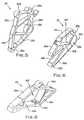
- Fig. 3 is a perspective view of a main beam support mounting bracket
- Fig. 4 is a perspective view of a driver beam
- Fig. 5 is a perspective view of a first support bracket
- Fig. 6 is a perspective view of a main beam hanger
- Fig. 7 is an end elevational view primarily illustrating a second support bracket
- Fig. 8 is a perspective view of a steering column support bracket
- Fig. 9 is a perspective view of a main beam support
- Fig. 10 is a rear elevational view of the main beam support of Fig. 9;
- Fig. 11 is a side view of the main beam support mounting bracket
- Fig. 12 is a front view of the main beam support mounting bracket
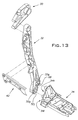
- Fig. 13 is an assembly view of the main beam hanger, the main beam support, the main beam support mounting bracket, and a stay;
- Fig. 14 is perspective view of the hanger beam assembly installed on a vehicle floor
- Fig. 15 is an exploded view of the hanger beam assembly with the vehicle floor
- Fig. 16 is a sectional view of the main beam support mounting bracket, the vehicle floor, and a cross-member;
- Fig. 17 is perspective view of the main beam support mounting bracket and the vehicle floor.
- an improved hanger beam assembly 20 including a driver beam 22, a main beam 24, a first or driver's side support bracket 26, a second or passenger's side support bracket 28, a main beam hanger 30, a main beam support 32, a main beam support mounting bracket 34, a center support 36, dashboard knee bolsters 38, steering column support brackets 40, a stay 42, a lower support beam 44, and a center support bracket 46.
- the hanger beam assembly 20 is a structural assembly to which a vehicle dashboard (not shown) is mounted and on which associated components of the vehicle, such as the steering column assembly, instrument panel, navigation and climate control panels, and glove box, are mounted. As such, the hanger beam assembly 20 extends generally across the entire width of the vehicle, between the driver's side and passenger's side A-pillars (not shown) provided by the vehicle frame.
- the components of the hanger beam assembly 20 are preferably formed from aluminum or an aluminum alloy. Components of the hanger beam assembly 20 are welded and/or bolted together to form a unitary, relatively stiff, structure, and cooperate to provide an improved or desirable natural frequency at the steering column assembly 37 (shown in dashed lines in Fig. 1A), which is secured to the hanger beam assembly 20 via the steering column support brackets 40. In the most preferred embodiment, the frequency at the steering column assembly 37 is about 42 Hz.
- the first support bracket 26 is secured to the vehicle driver's side A-pillar (not shown), and receives a first end 22a of the driver beam 22.
- the driver beam 22 extends between the first support bracket 26 and the main beam hanger 30, and has the dashboard knee bolsters 38 and steering column support brackets 40 affixed thereto at predetermined locations.
- the second end 22b of the driver beam 22 is received in the main beam hanger 30, and is supported thereby.
- the main beam hanger 30 supports both the second end 22b of the driver beam 22 and a first end 24a of the main beam 24, and is secured to and extends rearwardly therefrom to an upper end 32a of the main beam support 32.
- the main beam support 32 extends downwardly from the main beam hanger 30, and a lower end 32b of the main beam support 32 is secured to a first end 34a of the main beam support mounting bracket 34, which is affixed to a floor 52 and a frame cross-member 54 of the vehicle.
- the main beam 24 extends laterally from the main beam hanger 30 to the second support bracket 28.
- a second end 24b of the main beam 24 is secured to the second support bracket 28, which, in turn, is secured to the vehicle passenger's side A-pillar (not shown).
- the center support 36 extends between the main beam 24 and a second end 34b of the main beam support mounting bracket 34.
- the stay 42 extends laterally between the main beam support 32 and the center support 36.
- the lower support beam 44 extends between the main beam support 32 and the second support bracket 28 generally parallel to the main beam 24. While the lower support beam 44 is illustrated as being vertically generally even with the stay 42, this is not required.
- the driver beam 22 is preferably extruded from an aluminum alloy material so as to have a generally flat or planar bottom, front, and rear surfaces 22c, 22d, 22e, while a top surface 22f of the driver beam 22 slopes upwardly from an upper end of the front surface 22d and then curves rearwardly and downwardly to join with an upper end of the rear surface 22e.
- Providing the driver beam 22 with this asymmetrical cross-sectional profile ensures proper angular orientation of the driver beam 22 and positioning of components affixed thereto, while allowing the driver beam 22 to provide a desired strength for resistance to bending.
- Notches are formed in the driver beam 22 at the first and second ends 22a, 22b whereby the rear surface 22e, and portions of the bottom surface 22c and the top surface 22f are removed to define recessed portions whereby remaining portions of the top, front, and bottom surfaces define extending portions, as illustrated.
- the thus-modified first and second ends 22a, 22b of the driver beam 22 are adapted for receipt in the first support bracket 26 and the main beam hanger 30, respectively. More particularly, the driver beam first and second ends 22a, 22b may 'bottom out' when fully inserted into the first support bracket 26 and main beam hanger 30, as will be apparent from the drawings and the description to follow.
- the steering column brackets 40 include a peripheral framework 40a and first and second internal connecting members 40b, 40c.
- the peripheral framework 40a includes a planar dash mount 40d to which an upper dash panel (not shown) is secured.
- an inner surface of the peripheral framework includes a raised ledge 40e that serves as a stop or positioning means against which the driver beam rear surface 22e engages.
- the connecting members 40b, 40c and framework 40a cooperate to define an opening 40f in which the driver beam 22 is received, with the driver beam front surface 22d abutting a rearwardly facing surface of the first connecting member 40b and the bottom surface 22c and rearward portion of the top surface 22f of the driver beam 22 engaging the inner surfaces of the peripheral framework 40a.
- the steering column mounting brackets 40 are initially slidably arranged on the driver beam 22. Once the steering column mounting brackets 40 are placed in the predetermined positions, they are affixed to the driver beam 22 by placing a weld bead between each side of the steering column brackets 40 and the driver beam 22. Welding the steering column support brackets 40 to the driver beam 22 reinforces the driver beam 22 and further stiffens the resulting hanger beam assembly 20.
- the knee bolsters 38 which are positioned on each side of the steering column brackets 40, include a mounting end 38a having an upwardly open U-shaped profile that fits around the front, bottom, and rear surfaces 22d, 22c, 22e of the driver beam 22. Once the knee bolsters 38 are in the predetermined position, the mounting end 38a is welded to the driver beam 22 by placing a weld bead between each lateral side of the mounting ends 38a and the driver beam bottom, front, and rear surfaces 22c, 22d, 22e.
- the first support bracket 26 is preferably an extruded and subsequently machined aluminum part.
- the first support bracket 26 includes a peripheral framework 26a and upper and lower cross members 26b, 26c.
- the peripheral framework 26a defines a series of mounting holes 26d by means of which the first support bracket 26 may be mechanically affixed, via mounting screws, to the driver's side A-pillar.
- the first support bracket 25 is attached at three points to the A-pillar, as illustrated.
- the cross members 26b, 26c cooperate with the peripheral framework 26a to define a receptacle 26e into which the driver beam first end 22a is inserted and received.
- the peripheral framework includes an inner surface defining a raised ledge 26f.
- the ledge 26f serves as a stop to limit insertion of the driver beam first end into the receptacle 26e, as noted previously.
- the first support bracket 26 is welded to the driver beam 22, preferably by laying a weld bead between the first support bracket upper cross member 26b and the top surface 22f of the driver beam 22, so as to unify or integrate the first support bracket 26 and the driver beam 22.
- the stiffness of the resulting connecting is markedly increased as compared to the prior art.
- the main beam hanger 30 has an open lattice-like structure including a circular portion 30a, a crosspiece 30b, a curved top 30c, and a pair of mounting arms 30d.
- the circular portion 30a defines a main beam receptacle 30e.
- the circular portion 30a, crosspiece 30b, and curved top 30c cooperate to define a driver beam receptacle 30f.
- the inner surface of the curved top 30e includes a ledge 30g that serves as a stop to limit insertion of the driver beam second end 22b therein.
- the driver beam receptacle 30f is shaped and adapted to receive the second end 22b of the driver beam 22 from one side thereof facing toward the first support bracket 26.
- the main beam receptacle 30e is shaped and adapted to receive a first end 24a of the main beam 24 from the opposite side thereof (i.e., side facing toward the second support bracket 28).
- the preferred and illustrated main beam 24 is generally tubular in shape, and is preferably an aluminum extrusion.
- the main beam hanger 30 is welded to the driver beam 22, preferably by laying a weld bead between the hanger curved top 30c and the top surface 22f of the driver beam 22, so as to unify or integrate the hanger 30 and the driver beam 22.
- the interfitting of the driver beam 22 and the hanger 30 serves to greatly increase the resulting stiffness and structural integrity, as compared to the prior art.
- the main beam 24 is welded to the main beam hanger 30, preferably by a pair of welding beads placed on diametrically opposite positions along the periphery of the main beam 24, so as to positively secure the main beam 24 to the main beam hanger 30 for installation in the host vehicle and subsequent receipt of structural components.
- the main beam hanger 30 is positively secured to both the main beam 24 and the driver beam 22 by a plurality of welds. Further, the structural interlocks between the main beam 24, the driver beam 22, and the associated receptacles 26e, 30f; 30c serve to both position and stabilize the main beam hanger 30. Finally, the asymmetrical shape of the driver beam 22 insures that the main beam hanger 30 is properly angularly oriented.
- the main beam 24 extends laterally from the main beam hanger 30 to the second support bracket 28.
- An upper surface 28a of the second support bracket 28 defines a semi-circular recess 28b in which the second end 24b of the main beam 24 rests.
- the main beam second end 24b is welded to the second support bracket 28 by placing welding beads at positions on a rearwardly laterally outwardly facing surface of the second support bracket 28 and along a upper and lower peripheral surfaces of the main beam second end 24b.
- the main beam hanger mounting arms 30d extend rearwardly from the main beam hanger 30, and are positioned and adapted to be fixed to the main beam support 32 by a pair of fasteners that extend through threaded openings 30h formed in the mounting arms 30d adjacent their distal ends that align with corresponding threaded holes 32d formed in the main beam support 32.
- the main beam support 32 is preferably an aluminum casting and has an upper end 32a and a lower end 32b. It will be appreciated that the main beam support 32 is a rather complex part that includes a first lateral surface facing toward the first support bracket 26, a second lateral surface facing toward the second support bracket 28, a rear surface facing toward a rear of the vehicle, and a front surface facing toward a front of the vehicle.
- the first lateral surface of the main beam support upper end 32a includes mounting pads 32c that define the pair of threaded holes 32d for receipt of the fasteners for securement of the main beam hanger mounting arms 30d thereto. More specifically, the mounting arms 30d are brought into face-to-face engagement with the mounting pad 32c of the main beam support upper end 32a, and the openings 30h and holes 32d are aligned to permit the threaded fasteners to be installed to mechanically affix the main beam hanger 30 to the main beam support 32.
- the lower end 32b of the main beam support 32 includes first and second sockets 32e, 32f that are adapted to receive corresponding mounting posts 34d, 34e extending from the main beam support mounting bracket 34.
- the first and second sockets 32e, 32f are formed in the second lateral surface of the main beam support 32 such that the sockets 32e, 32f are open toward the second support bracket 28.
- the sockets 32e, 32f are somewhat elongated vertically, and have downwardly directed extensions 32i, 32j, as illustrated.
- each of the sockets 32e, 32f has a bottom surface (i.e., laterally facing toward the first support bracket 26) that is closed with the exception of a slotted opening 32g that is provided to permit a threaded fastener to extend therethrough.
- each socket 32e, 32f may be considered to be a laterally open blind bore that is adapted to receive the associated mounting post 34d, 34e.
- the first socket 32e is disposed relatively vertically above and rearward of the second socket 32f.
- the second socket 32f is generally disposed adjacent a lowermost end of the main beam support 32.
- the main beam support 32 includes a pair of mounts 32h that have threaded openings formed therein.
- the mounts 32h receive a first end 42a of the stay 42, and the threaded openings receive fasteners to mechanically affix the stay 42 to the main beam support 32.
- the main beam support mounting bracket 34 is preferably an aluminum casting that has a generally rectangular footprint with a bottom wall 34m, and includes a relatively raised first lateral end 34a facing toward the first mounting bracket 26, and a relatively shorter second lateral end 34b facing toward the second mounting bracket 28.
- the raised lateral end 34a has an end wall 34c from which the first and second mounting posts 34d, 34e laterally extend.
- the end wall 34c tapers as it extends vertically so as to provide a structurally stable attachment or mounting structure between the main beam support 32 and the frame cross-member 54.
- the first mounting post 34d is at a position that is relatively raised as compared to the second mounting post 34e.
- first mounting post 34d is positioned to be received in the first socket 32e, whereas the second mounting post 34e is disposed at a position to be received in the second socket 32f.
- Each of the first and second mounting posts 34d, 34e is generally cylindrical and has a threaded bore 34q formed centrally or axially therein through which a fastener, such as a bolt, is received to mechanically affix the main beam support lower end 32b to the main beam support mounting bracket 34.
- the fasteners are inserted through the slotted openings 32g in a back wall 32m of the sockets 32e, 32f and threaded into the mounting posts 34d, 34e so as to mechanically affix or clamp the main beam support 32 to the main beam support mounting bracket 34.
- receipt of the mounting posts 34d, 34e in the sockets 32e, 32f reduces or limits possible motion of the main beam support 32 in the forward/rearward and up/down directions, while the fasteners reduce or eliminate possible lateral motion of the main beam support 32 relative to the main beam support mounting bracket 34.
- the base wall 34m of the main beam support mounting bracket 34 provides a series of slotted mounting openings 34f.
- the main beam support mounting bracket 34 is attached to the vehicle floor 52 and frame cross-member 54 by passing fasteners through these slotted mounting openings 34f.
- Fig. 16 which is a sectional view along dotted line 16-16 of Fig. 14, a path for the fasteners is illustrated.
- the fasteners such as bolts, extend through openings 34f, 52f, 54f in the main beam support mounting bracket 34, the floor 52, and the frame cross-member 54, for threaded engagement with weld-nuts 54a.
- two of slotted mounting openings 34f are provided adjacent the first end 34a of the main beam support mounting bracket 34 and two of the slotted mounting openings 34f are provided adjacent the second end 34b of the main beam support mounting bracket 34.
- the bottom wall 34m of the main beam support mounting bracket 34 has a first planar surface 34n, a second planar surface 34o, and a third planar surface 34p.
- the first, second, and third planar surfaces 34n, 34o, 34p laterally extend between the first end 34a and the second end 34b of the main beam support mounting bracket 34.
- the first planar surface 34n extends generally horizontally toward the second planar surface 34o.
- the second planar surface 34o is inclined when extending from the first planar surface 34n to the third planar surface 34p.
- the third planar surface 34p extends generally horizontally in the longitudinal direction from the second planar surface 34p.
- the contour of the bottom wall 34m is shaped so as to cooperate with the floor 52 as will be discussed hereinafter.
- main beam support 32 is mechanically affixed to the main beam support mounting bracket 34
- main beam support mounting bracket 34 is mechanically affixed to the vehicle frame cross-member 54.
- main beam support mounting bracket posts 34d, 34e are received in the main beam support sockets 32e, 32f at a position that is vertically and horizontally offset from one another.
- the multi-point mechanical attachment and multi-plane engagement between the main beam support 32 and main beam support mounting bracket 34 results in a structurally stiff and secure integration of the main beam support 32 and main beam support mounting bracket 34.
- the second end 34b of the main beam support mounting bracket 34 includes first and second semi-cylindrical mounting pads 34g, 34h over which a lower end 36b of the center support 36 is placed, as will be apparent from the following description.
- the first and second mounting pads 34g, 34h extend vertically upwardly and have a small locating stub 34i at their upper end, and a laterally facing surface in which a threaded bore 34j is formed for receipt of a mounting fastener to secure the center support 36 thereto.
- the center support bracket 46 has a first end 46a secured to the main beam 24 and a second end 46b to which an upper end 36a of the center support 36 is secured.
- the center support bracket first end 46a is semi-circular and extends partway around the main beam 24, and the center support bracket 46 extends rearwardly therefrom.
- the center support bracket 46 is secured to the main beam 24 by upper and lower weld beads disposed between the free upper and lower terminal surfaces of the center support bracket 46 and the main beam 24.
- the center support 36 is generally shaped as an inverted L such that while the upper end 36a of the center support 36 is affixed to the second end 46b of the center support bracket 46 and extends rearwardly therefrom, a main portion of the center support 36 extends vertically downward to the lower end 36b of the center support 36. Intermediate the upper and lower ends 36a, 36b, the center support 36 is secured to the second end 42b of the stay 42, which serves to stabilize and maintain spacing between the main beam support 32 and the center support 36. Also, a first end 44a of the lower support beam 44 is secured to the center support 36 at a location intermediate the upper and lower ends 36a, 36b thereof, and extends first forwardly and then laterally toward the second support bracket 28, as illustrated. The second end 44b of the lower support beam 44 is bolted to the second support bracket 28.
- the lower end 36b of the center support 36 includes first and second downwardly open semi-cylindrical recesses (not shown).
- the recesses are also open in a lateral direction facing toward the first support bracket 26, such that the recesses define blind bores.
- the recesses include a vertical extension (not shown) for receipt of the mounting stubs 34i extending upwardly from the mounting pads 34g, 34h.
- a pair of threaded openings extends laterally through the lower end of the center support 36 and are aligned with the threaded bores 34j in the laterally facing surfaces of the mounting pads 34g, 34h.
- the mounting stubs 34i extend into the recess extensions, the mounting pads 34g, 34h are received in the recesses, and then bolts 48 (Fig. 1A) are threaded into the aligned openings and bores in the center support 36 and mounting pads 34g, 34h to mechanically affix the center support 36 to the main beam support mounting bracket 34.
- the hanger beam assembly 20 may be assembled in many different ways, the following is provided to generally describe one preferred method or sequence of assembly.
- the knee bolsters 38 and steering column support brackets 40 are first disposed at their predetermined positions along the length of the driver beam 22, and then welded thereto.
- the main beam hanger 30 is placed on the main beam 24, and welded thereto, and the first and second ends 22a, 22b of the driver beam 22 are pushed into the receptacles 26e, 30f in the first support bracket 26 and main beam hanger 30, respectively, and then welded thereto. This defines a first subassembly of the hanger beam assembly 20.
- first and second subassemblies are assembled by pushing the first end 24a of the main beam 24 into the receptacle 30e of the main beam hanger 30, and welding the main beam first end 24a to the main beam hanger 30.
- the so-assembled first and second subassemblies define a beam component.
- the stay second end 42b and lower support beam first end 44a are welded to the center support 36 to define a center support assembly. Thereafter, the center support assembly is secured to the main beam support mounting bracket 34 by bolting the lower end of the center support 36 to the mounting bracket 34 with fasteners that laterally extend. Then, the main beam support 32 is bolted to the main beam hanger 30 and the main beam support mounting bracket 34 to substantially complete the hanger beam assembly 20. Bolts laterally extend though the main beam support 32 and the main beam support mounting bracket 34.
- the assembled hanger beam assembly 20 may be installed in a vehicle by bolting the first support bracket 26 to the driver's side A-pillar, bolting the second support bracket 28 to the passenger's side A-pillar, and bolting the main beam support mounting bracket 34 to the vehicle floor 52 and frame cross-member 54 by fasteners that vertically extend downward and threadingly engage the weld-nets 54a that are attached to the frame cross-member 54.
- the following is provided to generally describe an alternative method of assembly of the main beam support 32 and the associated components. Due to dimensional differences of components of the hanger beam assembly 20 and alignment issues when installing the hanger beam assembly 20 into the vehicle, difficulties may be encountered after attaching the first and second support brackets 26, 28 to the respective A-pillars. Specifically, the main beam support mounting bracket 34 may not be at the proper elevation to allow connection to the vehicle floor 52 and frame cross-member 54. Alternatively, manufacturing requirements may dictate that the main beam support mounting bracket 34 be attached to the vehicle floor 52 and frame cross-member 54 before attachment to the main beam support 32.
- the main beam support mounting bracket 34 may be disconnected from the main beam support 32. Then, the main beam support mounting bracket 34, and hence the hanger beam assembly 20, may be adjusted in an up/down direction so as to alleviate the dimensional/alignment problems in the vertical direction between the hanger beam assembly 20 and the vehicle.
- the hanger beam assembly 20 may be moved in the up/down direction to adjust for dimensional/alignment problems in the vertical direction between the hanger beam assembly 20 and the vehicle.
- the oblong shaped first and second sockets 32e, 32f are larger in diameter than the mounting posts 34c, 34d. Accordingly, the first and second sockets 32e, 32f may accommodate elevational differences between the hanger beam assembly 20 and the main beam support mounting bracket 34.
- the main beam support mounting bracket 34 is mounted to the floor 52 and frame cross-member 54 with fasteners that extend through the slotted mounting openings 34f, the openings 52f, 54f and threadingly engage the weld-nuts 54a of the frame cross-member 54. Further, the main beam support 32 and the center support 36 are connected to the main beam support mounting bracket 34 with laterally extended fasteners.
- first and second sockets 32e, 32f of the main beam support 32 are adapted to receive the corresponding mounting posts 34c, 34d that extend from the main beam support mounting bracket 34.
- the first and second sockets 32e, 32f of the main beam support 32 include the downwardly directed extensions 32i, 32j for receipt of integral keys 34k, 34l of the mounting posts 34d, 34e.
- the main beam support 32 is disposed so that the first and second sockets 32e, 32f on the lower end 32b, engage the main beam support mounting bracket 34 on a first or right side, while the mounting pad 32c on the upper end 32a engage the main beam hanger 30 on a second side or left side.
- the first and second sockets 32e, 32f are oblong shaped. Furthermore, the first and second sockets 32e, 32f include perimeter walls 32k, 321 that extend in a generally horizontal direction from the back wall 32m of the main beam support 32.
- the oblong perimeter walls 32k, 32l receive the mounting posts 34d, 34e. It is noted that the downwardly directed extensions 32i, 32j created in the perimeter walls 32k, 32l have angled edges that aid in alignment and interaction with the integral keys 34k, 34l.
- the mounting posts 34d, 34e can be inserted into the oblong perimeter walls 32k, 321 until a front face of the mounting posts 34d, 34e contacts the back wall 32m of the first and second sockets 32e, 32f.
- the back wall 32m is a generally vertical wall that laterally faces toward the first support bracket 26.
- the back wall 32m includes the slotted opening 32g that receives a threaded fastener to attach the main beam support 32 with the main beam support mounting bracket 34.
- the mounting posts 34d, 34e are generally circular in shape and extend from the end wall 34c in a generally horizontal direction.
- the integral keys 34k, 34l extend downwardly in a height direction from the mounting posts 34d, 34e to a bottom wall 34m of the main beam support mounting bracket 34 at a constant height.
- the floor 52 extends in a generally horizontal plane in latitudinal and longitudinal directions along the vehicle.
- a variety of raised portions and holes are distributed along the floor 52.
- the raised portions and holes include side sill passageways 52a, a floor tunnel 52b, and openings 52f.
- a plurality of holes in the floor 52 allow fasteners to extend through for attaching various vehicle components with the vehicle frame (not shown) that is beneath the floor 52.
- the side sill passageways 52a accommodate vehicle side sills/frame rails (not shown) that extend along a length of the vehicle.
- the side sill passageways 52a include a vertical wall and a horizontal wall to receive the side sills/frame rails.
- the side sill passageways 52a may be of other shapes so as to properly accommodate the side sills/frame rails.
- the floor tunnel 52b is traditionally present to accommodate transmission components for the vehicle; however, the floor tunnel 52b may be present for a variety of other reasons.
- the floor tunnel 52a is composed of a top wall 52c, a first end wall 52d, a second end wall 52e, and an aft wall 52g.
- the first end wall 52d, the second end wall 52e, and the aft wall 52g are generally inclined as they extend from the floor 52 and terminate into the top wall 52c.
- the top wall 52c has a first surface 52h, a second surface 52i, and a third surface 52j.
- the first, second, and third surfaces 52h, 52i, 52j laterally extend in a vehicle width direction between the first end wall 52d and the second end wall 52e.
- the first surface 52h extends generally horizontally between the aft wall 52g and the second surface 52i.
- the second surface 52i is inclined when extending from the first surface 52h to the third surface 52j.
- the third surface 52j extends generally horizontally in the longitudinal direction from the second surface 52i.
- the frame cross-member 54 because of the shape of the frame cross-member 54, a portion of the frame cross-member 54 can be received by the floor tunnel 52b.
- the shape of the frame cross-member 54 is not central to the present invention. Rather, the presence of the weld-nuts 54a on the frame cross-member 54 allows for the main beam support mounting bracket 34 to be attached to the cross-member 54 with downwardly directed fasteners.
- the cross-member 54 is further attached to the main vehicle frame or vehicle uni-body structural members.
- the first planar surface 34n of the main beam support mounting bracket 34 interacts with the first surface 52h of the floor tunnel 52b.
- the second planar surface 34o of the main beam support mounting bracket 34 interacts with the second surface 52i of the floor tunnel 52b.
- the third planar surface 34p of the main beam support mounting bracket 34 interacts with the third surface 52j of the floor tunnel 52b.
- planar surfaces 34n, 34o, 34p of the bottom wall 34m of the main beam support mounting bracket 34 are coplanar with the respective surfaces 52h, 52i, 52j of the floor tunnel 52b, a rigid and secure connection is ensured for the main beam support mounting bracket 34 and hence, the hanger beam assembly 20. Furthermore, because of the shape of the top wall 52c of the floor tunnel 52b, additional space beneath the floor tunnel 52b is created to accommodate larger components than if the top wall 52c were merely horizontal.
- Fasteners extend from the main beam support mounting bracket 34 through the floor 52 and the frame cross-member 54. As mentioned hereinbefore, the fasteners generally extend vertically downward through the openings 34f, 52f, and 54f in the main beam support mounting bracket 34, the floor 52f, and the frame cross-member 54. On an interior surface of the frame cross-member, the weld-nuts 54a are provided. The weld-nuts 54a threadingly engage these fasteners.
- the weld-nuts 54a are of a common construction and are known in the art.
- the main beam support 32 and the center support 36 may be secured to the main beam support mounting bracket 34 with laterally-directed bolts. These bolts extend through the slotted opening 32g and the associated hole in the main beam support mounting bracket 34 and through the center support 36 and the threaded bores 34j of the main beam support mounting bracket 34 with the bolts 48. Because the main beam support 32 and the center support 36 are attached to the main beam support mounting bracket 34 with laterally extending fasteners, additional strength and rigidity is afforded to the hanger beam assembly 20.
- the integral keys 34k, 34l cooperate with the downwardly directed extensions 32i, 32j of the first and second sockets 32e, 32f during assembly as will be more fully described hereinafter. From a side view as is shown in Fig. 11, as the integral keys 34k, 341 extend downward, the integral keys 34k, 34l preferably taper in thickness from a maximum thickness near the mounting posts 34d, 34e to a minimum thickness near the bottom wall 34m of the main beam support mounting bracket 34. It should be noted that the integral keys 34k, 34l could maintain a uniform thickness between the mounting posts 34d, 34e and the bottom wall 34m.
- Fig. 12 illustrates that the integral keys 34k, 341 laterally extend from the end wall 34e along a length of the mounting posts 34d, 34e. As is also shown in Fig. 12, the integral keys 34k, 341 extend in a constant height direction between the mounting posts 34d, 34e and the bottom wall 34m.
- Fig. 13 illustrates a main beam support assembly 20.
- the integral keys 34k, 34l may interface with angled edges of the downwardly directed extensions 32i, 32j so as to better align the main beam support 32 with the main beam support mounting bracket 34, thereby simplifying installation of a fastener through the slotted opening 32g and the associated hole in the main beam support mounting bracket 34.
- the interaction between the integral keys 34k, 341 with the downwardly directed extensions 32i, 32j is somewhat similar to that of a key and a keyway arrangement as is known in the art.
- the thickness of the integral keys 34k, 341 is preferably tapered. This provides a convenient means to align the main beam support 32 with the main beam support mounting bracket 34, while still allowing for adjustment of the main beam support 32 in the vertical direction.
- integral keys 34k, 34l may rest on the angled edges of the downwardly directed extensions 32i, 32j any force that would be transmitted to the mounting posts 34d, 34e is also distributed through the integral keys 34k, 34l to the angled edges of the downwardly directed extensions 32i, 32j and into the perimeter walls 32k, 321.
- the external diameter of the mounting posts 34d, 34e is less than the internal diameter of the perimeter walls 32k, 32l of the first and second sockets 32e, 32f.
- the mounting posts 34d, 34e are of a generally undersized circular cross-section, while the perimeter walls 32k, 321 of the first and second sockets 32e, 32f are of a generally oblong oversized shape. Because of this, additional freedom in the horizontal and vertical directions is allowed when aligning the main beam support 32 and the main beam support mounting bracket 34. As mentioned hereinbefore, the slotted openings 32g also assist in allowing additional freedom of movement during alignment of the components.
- At least a portion of the thickness of the integral keys 34k, 341 is less than a width of the downwardly directed extensions 32i, 32j. This ensures that that the main beam support 32 can be aligned with the main beam support mounting bracket 34.
- the hanger beam assembly 20 of the present invention provides a relatively light-weight structure to which the steering column assembly, dashboard and associated components may be secured. Further, the components of the hanger beam assembly 20 provide a desired natural frequency at the steering wheel. More specifically, it has been found that the natural frequency at the steering wheel is affected by the hanger beam assembly 20 materials as well as the spacing between the steering column and the driver beam 22 to which the steering column assembly, via the steering column support brackets 40, is secured. By forming the hanger beam assembly 20 from aluminum, it is possible to provide a desired natural frequency (e.g., 42 Hz) at the steering column assembly 37 while retaining a relatively short spacing.
- a desired natural frequency e.g., 42 Hz
- the structural integration and cooperation between the driver beam 22, first support bracket 26, steering column support brackets 40, main beam hanger 30, main beam support 32, and main beam support mounting bracket 34 is considered to directly affect the frequency response at the steering column assembly 37.
- the desired natural frequency at the steering column assembly 37 results.
- This result is an improvement over known steel hanger beam assemblies in which, at the identical desired spacing, inherently provides a natural frequency that is reduced (i.e., about 33 Hz) and therefore has an undesirably frequency response.
- the main beam support 32 of the present invention greatly simplifies assembly of the hanger beam assembly 20. Specifically, assembly of the main beam support 32 with the main beam hanger 30 and the main beam support mounting bracket 34 is improved.
- the first socket 32e is disposed relatively vertically above and rearward of the second socket 32f.
- the mounting posts 34d, 34e of the main beam support mounting bracket 34 are disposed so as to be aligned with the first and second sockets 32e, 32f.
- the first and second sockets 32e, 32f are oblong and oversized, they easily receive the undersized circular mounting posts 34d, 34e. This allows for increased accommodation of differences in vertical space between the main beam support 32 and the main beam hanger 20.
- the pair of threaded holes 32d allow for the receipt of the fasteners for securement of the main beam hanger mounting arms 30d.
- This multi-point mechanical attachment and multi-plane engagement at the upper and lower ends 32a, 32b results in a secure connection between the main beam support 32 and main beam support mounting bracket 34.
- the sockets 32e, 32f only limit possible motion of the main beam support 32 in the forward/rearward and up/down directions after being aligned with the main beam support mounting bracket 34. It is not until fasteners are passed through the slotted opening 32g that lateral motion of the main beam support 32, relative to the main beam support mounting bracket 34, is prevented. Accordingly, dimensional flaws in the hanger beam assembly 20 can be accommodated, thereby simplifying installation and assembly of the hanger beam assembly 20 in the vehicle.
- the shape of the bottom wall 34m of the main beam support mounting bracket 34 provides a secure and rigid interface with the floor tunnel 52b and frame cross-member 54.
- the fasteners that extend downward through the main beam support mounting bracket 34 into the frame cross-member 54 further enhance hanger beam assembly strength.
- the hanger beam assembly 20 is strengthened.
- a hanger beam assembly is formed from aluminum and includes first and second support brackets, a main beam hanger, a driver beam, a main beam, a main beam support, and a main beam support mounting bracket.
- the main beam support mounting bracket has a first lateral end that is mechanically secured to the main beam support and a second lateral end that is mechanically secured to a center support.
- a bottom wall of the main beam support mounting bracket includes slotted mounting openings for receipt of fasteners for attachment to a floor tunnel of a vehicle floor and frame cross-member.
- the bottom wall includes first, second, and third planar surfaces that interact with first, second, and third surfaces of the floor tunnel in the vehicle.
- the resulting hanger beam assembly is light-weight and provides a desired natural frequency at the associated steering wheel.
Landscapes
- Engineering & Computer Science (AREA)
- Chemical & Material Sciences (AREA)
- Combustion & Propulsion (AREA)
- Transportation (AREA)
- Mechanical Engineering (AREA)
- Body Structure For Vehicles (AREA)
Abstract
Description
- The present invention is directed toward an aluminum hanger beam assembly for a vehicle.
- Many hanger beam assemblies are known in the art. Such assemblies are structural components that extend between the vehicle A-pillars and serve as a mount for the vehicle dashboard, instrument panels, control panels, and a steering column assembly. Conventionally hanger beam assemblies are formed from a variety of steel components, typically steel tubes and stampings, which are mechanically affixed to one another to form a relatively unitary structure.
- Unfortunately, while steel is a durable and reliable material, it is relatively heavy. Naturally, there exists a desire to reduce the weight of the vehicle so as to improve fuel efficiency.
- Further, steel has an inherent frequency response which, at a desired spacing between the hanger beam assembly and the steering wheel of the associated steering column assembly, results in an undesirable natural frequency. For example, in some vehicles the natural frequency is about 33 HZ, whereas the desired natural frequency is about 42 Hz. Unfortunately, in conventional steel assemblies such a desired natural frequency cannot be attained without adding even more weight to the system.
- Therefore, there exists a need in the art for a hanger beam assembly that is made from a lighter material while providing the desired natural frequency to the steering column assembly. Furthermore, there exists a need in the art for a hanger beam assembly that provides a secure and stiff connection between components in the vehicle.
- The present invention is directed toward a hanger beam assembly for use in a vehicle. The hanger beam assembly comprising a first support bracket and a second support bracket. The first support bracket being adapted to be secured to a first A-pillar and the second support bracket being adapted to be secured to a second A-pillar. The hanger beam assembly further comprising a main beam hanger, a driver beam having a first end and a second end. The first end being affixed to the first support bracket. The second end being affixed to the main beam hanger. The hanger beam assembly further comprising a main beam having a first end and a second end. The main beam first end being affixed to the main beam hanger. The main beam second end being received by said second support bracket. The hanger beam assembly further comprising a main beam support and a main beam support mounting bracket.
- In accordance with the present invention, the main beam support mounting bracket is affixed to a floor of the vehicle, and the main beam support has an upper end that is mechanically secured to the main beam hanger and a lower end that is mechanically secured to the main beam support mounting bracket.
- These and further features of the invention will be apparent with reference to the following description and drawings, wherein:
- Fig. 1A is a perspective view of the hanger beam assembly according to the present invention;
- Fig. 1 B is a rear elevational view of the hanger beam assembly of Fig. 1 A;
- Fig. 1C is a top plan view of the hanger beam assembly of Figs. 1A and 1 B;
- Fig. 2 is a side view, partially in cross section, of a portion of the hanger beam assembly as seen along line 2-2 of Fig. 1 B;
- Fig. 3 is a perspective view of a main beam support mounting bracket;
- Fig. 4 is a perspective view of a driver beam;
- Fig. 5 is a perspective view of a first support bracket;
- Fig. 6 is a perspective view of a main beam hanger;
- Fig. 7 is an end elevational view primarily illustrating a second support bracket;
- Fig. 8 is a perspective view of a steering column support bracket;
- Fig. 9 is a perspective view of a main beam support;
- Fig. 10 is a rear elevational view of the main beam support of Fig. 9;
- Fig. 11 is a side view of the main beam support mounting bracket;
- Fig. 12 is a front view of the main beam support mounting bracket;
- Fig. 13 is an assembly view of the main beam hanger, the main beam support, the main beam support mounting bracket, and a stay;
- Fig. 14 is perspective view of the hanger beam assembly installed on a vehicle floor;
- Fig. 15 is an exploded view of the hanger beam assembly with the vehicle floor;
- Fig. 16 is a sectional view of the main beam support mounting bracket, the vehicle floor, and a cross-member; and
- Fig. 17 is perspective view of the main beam support mounting bracket and the vehicle floor.
- With reference to the drawings, the present invention is directed toward an improved
hanger beam assembly 20 including adriver beam 22, amain beam 24, a first or driver'sside support bracket 26, a second or passenger'sside support bracket 28, amain beam hanger 30, amain beam support 32, a main beamsupport mounting bracket 34, acenter support 36,dashboard knee bolsters 38, steeringcolumn support brackets 40, astay 42, alower support beam 44, and acenter support bracket 46. - As will be appreciated by those skilled in the art, the
hanger beam assembly 20 is a structural assembly to which a vehicle dashboard (not shown) is mounted and on which associated components of the vehicle, such as the steering column assembly, instrument panel, navigation and climate control panels, and glove box, are mounted. As such, thehanger beam assembly 20 extends generally across the entire width of the vehicle, between the driver's side and passenger's side A-pillars (not shown) provided by the vehicle frame. - As will be discussed more fully hereinafter, the components of the
hanger beam assembly 20, are preferably formed from aluminum or an aluminum alloy. Components of thehanger beam assembly 20 are welded and/or bolted together to form a unitary, relatively stiff, structure, and cooperate to provide an improved or desirable natural frequency at the steering column assembly 37 (shown in dashed lines in Fig. 1A), which is secured to thehanger beam assembly 20 via the steeringcolumn support brackets 40. In the most preferred embodiment, the frequency at thesteering column assembly 37 is about 42 Hz. - Generally, and with primary reference to Figs. 1A-1C, the
first support bracket 26 is secured to the vehicle driver's side A-pillar (not shown), and receives afirst end 22a of thedriver beam 22. Thedriver beam 22 extends between thefirst support bracket 26 and themain beam hanger 30, and has thedashboard knee bolsters 38 and steeringcolumn support brackets 40 affixed thereto at predetermined locations. Thus, thesecond end 22b of thedriver beam 22 is received in themain beam hanger 30, and is supported thereby. Themain beam hanger 30 supports both thesecond end 22b of thedriver beam 22 and afirst end 24a of themain beam 24, and is secured to and extends rearwardly therefrom to anupper end 32a of themain beam support 32. - The
main beam support 32 extends downwardly from themain beam hanger 30, and alower end 32b of themain beam support 32 is secured to afirst end 34a of the main beamsupport mounting bracket 34, which is affixed to afloor 52 and aframe cross-member 54 of the vehicle. Themain beam 24 extends laterally from themain beam hanger 30 to thesecond support bracket 28. Thus, asecond end 24b of themain beam 24 is secured to thesecond support bracket 28, which, in turn, is secured to the vehicle passenger's side A-pillar (not shown). Thecenter support 36 extends between themain beam 24 and asecond end 34b of the main beamsupport mounting bracket 34. Thestay 42 extends laterally between themain beam support 32 and thecenter support 36. Thelower support beam 44 extends between themain beam support 32 and thesecond support bracket 28 generally parallel to themain beam 24. While thelower support beam 44 is illustrated as being vertically generally even with thestay 42, this is not required. - More specifically, and initially with reference to Fig. 4, the
driver beam 22 is preferably extruded from an aluminum alloy material so as to have a generally flat or planar bottom, front, andrear surfaces top surface 22f of thedriver beam 22 slopes upwardly from an upper end of thefront surface 22d and then curves rearwardly and downwardly to join with an upper end of therear surface 22e. Providing thedriver beam 22 with this asymmetrical cross-sectional profile ensures proper angular orientation of thedriver beam 22 and positioning of components affixed thereto, while allowing thedriver beam 22 to provide a desired strength for resistance to bending. - Notches are formed in the
driver beam 22 at the first andsecond ends rear surface 22e, and portions of thebottom surface 22c and thetop surface 22f are removed to define recessed portions whereby remaining portions of the top, front, and bottom surfaces define extending portions, as illustrated. The thus-modified first andsecond ends driver beam 22 are adapted for receipt in thefirst support bracket 26 and themain beam hanger 30, respectively. More particularly, the driver beam first andsecond ends first support bracket 26 andmain beam hanger 30, as will be apparent from the drawings and the description to follow. By providing this cooperating structure between the driver beam ends 22a, 22b and thefirst support bracket 26 and themain beam hanger 30, a secure mechanical connection is provide that stiffens the resultinghanger beam assembly 20 without requiring additional mechanical fasteners. - Right and left steering
column support brackets 40 and right and left knee bolsters 38 are mounted on thedriver beam 22 at predetermined locations between the first andsecond ends steering column brackets 40 include aperipheral framework 40a and first and second internal connectingmembers peripheral framework 40a includes aplanar dash mount 40d to which an upper dash panel (not shown) is secured. Between the first and second connectingmembers ledge 40e that serves as a stop or positioning means against which the driver beamrear surface 22e engages. - Thus, the connecting
members framework 40a cooperate to define anopening 40f in which thedriver beam 22 is received, with the driver beamfront surface 22d abutting a rearwardly facing surface of the first connectingmember 40b and thebottom surface 22c and rearward portion of thetop surface 22f of thedriver beam 22 engaging the inner surfaces of theperipheral framework 40a. As such, the steeringcolumn mounting brackets 40 are initially slidably arranged on thedriver beam 22. Once the steeringcolumn mounting brackets 40 are placed in the predetermined positions, they are affixed to thedriver beam 22 by placing a weld bead between each side of thesteering column brackets 40 and thedriver beam 22. Welding the steeringcolumn support brackets 40 to thedriver beam 22 reinforces thedriver beam 22 and further stiffens the resultinghanger beam assembly 20. - The knee bolsters 38, which are positioned on each side of the
steering column brackets 40, include a mounting end 38a having an upwardly open U-shaped profile that fits around the front, bottom, andrear surfaces driver beam 22. Once the knee bolsters 38 are in the predetermined position, the mounting end 38a is welded to thedriver beam 22 by placing a weld bead between each lateral side of the mounting ends 38a and the driver beam bottom, front, andrear surfaces - With reference to Fig. 5, the
first support bracket 26 is preferably an extruded and subsequently machined aluminum part. Thefirst support bracket 26 includes aperipheral framework 26a and upper andlower cross members peripheral framework 26a defines a series of mountingholes 26d by means of which thefirst support bracket 26 may be mechanically affixed, via mounting screws, to the driver's side A-pillar. Preferably, the first support bracket 25 is attached at three points to the A-pillar, as illustrated. Thecross members peripheral framework 26a to define areceptacle 26e into which the driver beamfirst end 22a is inserted and received. The peripheral framework includes an inner surface defining a raisedledge 26f. Theledge 26f serves as a stop to limit insertion of the driver beam first end into thereceptacle 26e, as noted previously. - Once the
first end 22a of thedriver beam 22 is inserted into thereceptacle 26e provided by thefirst support bracket 26, thefirst support bracket 26 is welded to thedriver beam 22, preferably by laying a weld bead between the first support bracketupper cross member 26b and thetop surface 22f of thedriver beam 22, so as to unify or integrate thefirst support bracket 26 and thedriver beam 22. By interfitting and subsequently welding thedriver beam 22 and thefirst support bracket 26, the stiffness of the resulting connecting is markedly increased as compared to the prior art. - With reference to Fig. 6, the
main beam hanger 30 has an open lattice-like structure including acircular portion 30a, acrosspiece 30b, a curved top 30c, and a pair of mountingarms 30d. Thecircular portion 30a defines amain beam receptacle 30e. Thecircular portion 30a,crosspiece 30b, and curved top 30c cooperate to define adriver beam receptacle 30f. The inner surface of the curved top 30e includes aledge 30g that serves as a stop to limit insertion of the driver beamsecond end 22b therein. - The
driver beam receptacle 30f is shaped and adapted to receive thesecond end 22b of thedriver beam 22 from one side thereof facing toward thefirst support bracket 26. Similarly, themain beam receptacle 30e is shaped and adapted to receive afirst end 24a of themain beam 24 from the opposite side thereof (i.e., side facing toward the second support bracket 28). The preferred and illustratedmain beam 24 is generally tubular in shape, and is preferably an aluminum extrusion. - Once the
second end 22b of thedriver beam 22 is inserted into thedriver beam receptacle 30f provided by the main beam hanger 30 (i.e., bottom out), themain beam hanger 30 is welded to thedriver beam 22, preferably by laying a weld bead between the hanger curved top 30c and thetop surface 22f of thedriver beam 22, so as to unify or integrate thehanger 30 and thedriver beam 22. As with the connection between the driver beam and thefirst support bracket 26, the interfitting of thedriver beam 22 and thehanger 30 serves to greatly increase the resulting stiffness and structural integrity, as compared to the prior art. Similarly, once thefirst end 24a of themain beam 24 is inserted into themain beam receptacle 30e, themain beam 24 is welded to themain beam hanger 30, preferably by a pair of welding beads placed on diametrically opposite positions along the periphery of themain beam 24, so as to positively secure themain beam 24 to themain beam hanger 30 for installation in the host vehicle and subsequent receipt of structural components. - As such, the
main beam hanger 30 is positively secured to both themain beam 24 and thedriver beam 22 by a plurality of welds. Further, the structural interlocks between themain beam 24, thedriver beam 22, and the associatedreceptacles main beam hanger 30. Finally, the asymmetrical shape of thedriver beam 22 insures that themain beam hanger 30 is properly angularly oriented. - The
main beam 24 extends laterally from themain beam hanger 30 to thesecond support bracket 28. Anupper surface 28a of thesecond support bracket 28 defines asemi-circular recess 28b in which thesecond end 24b of themain beam 24 rests. Preferably, the main beamsecond end 24b is welded to thesecond support bracket 28 by placing welding beads at positions on a rearwardly laterally outwardly facing surface of thesecond support bracket 28 and along a upper and lower peripheral surfaces of the main beamsecond end 24b. - The main beam
hanger mounting arms 30d extend rearwardly from themain beam hanger 30, and are positioned and adapted to be fixed to themain beam support 32 by a pair of fasteners that extend through threadedopenings 30h formed in the mountingarms 30d adjacent their distal ends that align with corresponding threadedholes 32d formed in themain beam support 32. - With reference to Figs. 9-10, the
main beam support 32 is preferably an aluminum casting and has anupper end 32a and alower end 32b. It will be appreciated that themain beam support 32 is a rather complex part that includes a first lateral surface facing toward thefirst support bracket 26, a second lateral surface facing toward thesecond support bracket 28, a rear surface facing toward a rear of the vehicle, and a front surface facing toward a front of the vehicle. - The first lateral surface of the main beam support
upper end 32a includes mountingpads 32c that define the pair of threadedholes 32d for receipt of the fasteners for securement of the main beamhanger mounting arms 30d thereto. More specifically, the mountingarms 30d are brought into face-to-face engagement with the mountingpad 32c of the main beam supportupper end 32a, and theopenings 30h andholes 32d are aligned to permit the threaded fasteners to be installed to mechanically affix themain beam hanger 30 to themain beam support 32. - The
lower end 32b of themain beam support 32 includes first andsecond sockets posts support mounting bracket 34. The first andsecond sockets main beam support 32 such that thesockets second support bracket 28. Preferably, thesockets extensions sockets opening 32g that is provided to permit a threaded fastener to extend therethrough. Thus, eachsocket post first socket 32e is disposed relatively vertically above and rearward of thesecond socket 32f. Thesecond socket 32f is generally disposed adjacent a lowermost end of themain beam support 32. - Intermediate the upper and
lower ends main beam support 32 includes a pair ofmounts 32h that have threaded openings formed therein. Themounts 32h receive a first end 42a of thestay 42, and the threaded openings receive fasteners to mechanically affix thestay 42 to themain beam support 32. - With reference to Fig. 3, the main beam
support mounting bracket 34 is preferably an aluminum casting that has a generally rectangular footprint with abottom wall 34m, and includes a relatively raised firstlateral end 34a facing toward the first mountingbracket 26, and a relatively shorter secondlateral end 34b facing toward the second mountingbracket 28. The raisedlateral end 34a has anend wall 34c from which the first and second mountingposts end wall 34c tapers as it extends vertically so as to provide a structurally stable attachment or mounting structure between themain beam support 32 and theframe cross-member 54. The first mountingpost 34d is at a position that is relatively raised as compared to the second mountingpost 34e. Thus, the first mountingpost 34d is positioned to be received in thefirst socket 32e, whereas the second mountingpost 34e is disposed at a position to be received in thesecond socket 32f. Each of the first and second mountingposts lower end 32b to the main beamsupport mounting bracket 34. - Preferably, the fasteners are inserted through the slotted
openings 32g in a back wall 32m of thesockets posts main beam support 32 to the main beamsupport mounting bracket 34. It will be appreciated that receipt of the mountingposts sockets main beam support 32 in the forward/rearward and up/down directions, while the fasteners reduce or eliminate possible lateral motion of themain beam support 32 relative to the main beamsupport mounting bracket 34. - As is shown in Figs. 14-15, the
base wall 34m of the main beamsupport mounting bracket 34 provides a series of slotted mountingopenings 34f. The main beamsupport mounting bracket 34 is attached to thevehicle floor 52 andframe cross-member 54 by passing fasteners through these slotted mountingopenings 34f. - With particular reference to Fig. 16, which is a sectional view along dotted line 16-16 of Fig. 14, a path for the fasteners is illustrated. The fasteners, such as bolts, extend through
openings support mounting bracket 34, thefloor 52, and theframe cross-member 54, for threaded engagement with weld-nuts 54a. Preferably, two of slotted mountingopenings 34f are provided adjacent thefirst end 34a of the main beamsupport mounting bracket 34 and two of the slotted mountingopenings 34f are provided adjacent thesecond end 34b of the main beamsupport mounting bracket 34. - The
bottom wall 34m of the main beamsupport mounting bracket 34 has a firstplanar surface 34n, a second planar surface 34o, and a thirdplanar surface 34p. The first, second, and thirdplanar surfaces first end 34a and thesecond end 34b of the main beamsupport mounting bracket 34. In a longitudinal direction of the vehicle, the firstplanar surface 34n extends generally horizontally toward the second planar surface 34o. The second planar surface 34o is inclined when extending from the firstplanar surface 34n to the thirdplanar surface 34p. The thirdplanar surface 34p extends generally horizontally in the longitudinal direction from the secondplanar surface 34p. The contour of thebottom wall 34m is shaped so as to cooperate with thefloor 52 as will be discussed hereinafter. - Thus, the
main beam support 32 is mechanically affixed to the main beamsupport mounting bracket 34, and the main beamsupport mounting bracket 34 is mechanically affixed to thevehicle frame cross-member 54. Further, the main beam support mountingbracket posts beam support sockets main beam support 32 and main beamsupport mounting bracket 34 results in a structurally stiff and secure integration of themain beam support 32 and main beamsupport mounting bracket 34. - With reference to Figs. 1A, 3, and 13, the
second end 34b of the main beamsupport mounting bracket 34 includes first and secondsemi-cylindrical mounting pads center support 36 is placed, as will be apparent from the following description. The first andsecond mounting pads small locating stub 34i at their upper end, and a laterally facing surface in which a threadedbore 34j is formed for receipt of a mounting fastener to secure thecenter support 36 thereto. - The
center support bracket 46 has a first end 46a secured to themain beam 24 and a second end 46b to which an upper end 36a of thecenter support 36 is secured. The center support bracket first end 46a is semi-circular and extends partway around themain beam 24, and thecenter support bracket 46 extends rearwardly therefrom. Preferably, thecenter support bracket 46 is secured to themain beam 24 by upper and lower weld beads disposed between the free upper and lower terminal surfaces of thecenter support bracket 46 and themain beam 24. - The
center support 36 is generally shaped as an inverted L such that while the upper end 36a of thecenter support 36 is affixed to the second end 46b of thecenter support bracket 46 and extends rearwardly therefrom, a main portion of thecenter support 36 extends vertically downward to the lower end 36b of thecenter support 36. Intermediate the upper and lower ends 36a, 36b, thecenter support 36 is secured to the second end 42b of thestay 42, which serves to stabilize and maintain spacing between themain beam support 32 and thecenter support 36. Also, a first end 44a of thelower support beam 44 is secured to thecenter support 36 at a location intermediate the upper and lower ends 36a, 36b thereof, and extends first forwardly and then laterally toward thesecond support bracket 28, as illustrated. The second end 44b of thelower support beam 44 is bolted to thesecond support bracket 28. - The lower end 36b of the
center support 36 includes first and second downwardly open semi-cylindrical recesses (not shown). The recesses are also open in a lateral direction facing toward thefirst support bracket 26, such that the recesses define blind bores. Further, the recesses include a vertical extension (not shown) for receipt of the mountingstubs 34i extending upwardly from the mountingpads center support 36 and are aligned with the threadedbores 34j in the laterally facing surfaces of the mountingpads - Thus, when the
center support 36 is positioned on the main beamsupport mounting bracket 34, the mountingstubs 34i extend into the recess extensions, the mountingpads center support 36 and mountingpads center support 36 to the main beamsupport mounting bracket 34. - While it is considered apparent that the
hanger beam assembly 20 may be assembled in many different ways, the following is provided to generally describe one preferred method or sequence of assembly. During assembly, preferably the knee bolsters 38 and steeringcolumn support brackets 40 are first disposed at their predetermined positions along the length of thedriver beam 22, and then welded thereto. Thereafter, themain beam hanger 30 is placed on themain beam 24, and welded thereto, and the first andsecond ends driver beam 22 are pushed into thereceptacles first support bracket 26 andmain beam hanger 30, respectively, and then welded thereto. This defines a first subassembly of thehanger beam assembly 20. Then, thesecond end 24b of themain beam 24 placed on thesemi-circular recess 28b of the second support bracket and welded thesecond support bracket 28, and thecenter support bracket 46 is positioned on themain beam 24 and welded thereto. This defines a second subassembly for thehanger beam assembly 20. - Thereafter, the first and second subassemblies are assembled by pushing the
first end 24a of themain beam 24 into thereceptacle 30e of themain beam hanger 30, and welding the main beamfirst end 24a to themain beam hanger 30. The so-assembled first and second subassemblies define a beam component. - The stay second end 42b and lower support beam first end 44a are welded to the
center support 36 to define a center support assembly. Thereafter, the center support assembly is secured to the main beamsupport mounting bracket 34 by bolting the lower end of thecenter support 36 to the mountingbracket 34 with fasteners that laterally extend. Then, themain beam support 32 is bolted to themain beam hanger 30 and the main beamsupport mounting bracket 34 to substantially complete thehanger beam assembly 20. Bolts laterally extend though themain beam support 32 and the main beamsupport mounting bracket 34. Thereafter, the assembledhanger beam assembly 20 may be installed in a vehicle by bolting thefirst support bracket 26 to the driver's side A-pillar, bolting thesecond support bracket 28 to the passenger's side A-pillar, and bolting the main beamsupport mounting bracket 34 to thevehicle floor 52 andframe cross-member 54 by fasteners that vertically extend downward and threadingly engage the weld-nets 54a that are attached to theframe cross-member 54. - The following is provided to generally describe an alternative method of assembly of the
main beam support 32 and the associated components. Due to dimensional differences of components of thehanger beam assembly 20 and alignment issues when installing thehanger beam assembly 20 into the vehicle, difficulties may be encountered after attaching the first andsecond support brackets support mounting bracket 34 may not be at the proper elevation to allow connection to thevehicle floor 52 andframe cross-member 54. Alternatively, manufacturing requirements may dictate that the main beamsupport mounting bracket 34 be attached to thevehicle floor 52 andframe cross-member 54 before attachment to themain beam support 32. - Because of the oblong shaped first and
second sockets support mounting bracket 34 has been attached to thehanger beam assembly 20 and it is discovered that the main beamsupport mounting bracket 34 is at an elevation that prevents attachment to thevehicle floor 52 and theframe cross-member 54, the main beamsupport mounting bracket 34 may be disconnected from themain beam support 32. Then, the main beamsupport mounting bracket 34, and hence thehanger beam assembly 20, may be adjusted in an up/down direction so as to alleviate the dimensional/alignment problems in the vertical direction between thehanger beam assembly 20 and the vehicle. - In addition, when the main beam
support mounting bracket 34 is already attached to thevehicle floor 52 and theframe cross-member 54, but not attached to themain beam support 32, the above described method is equally applicable. Thehanger beam assembly 20 may be moved in the up/down direction to adjust for dimensional/alignment problems in the vertical direction between thehanger beam assembly 20 and the vehicle. The oblong shaped first andsecond sockets posts second sockets hanger beam assembly 20 and the main beamsupport mounting bracket 34. - As with any of the methods mentioned hereinbefore, the main beam
support mounting bracket 34 is mounted to thefloor 52 andframe cross-member 54 with fasteners that extend through the slotted mountingopenings 34f, theopenings frame cross-member 54. Further, themain beam support 32 and thecenter support 36 are connected to the main beamsupport mounting bracket 34 with laterally extended fasteners. - As mentioned hereinbefore, the first and
second sockets main beam support 32 are adapted to receive the corresponding mountingposts support mounting bracket 34. The first andsecond sockets main beam support 32 include the downwardly directedextensions integral keys 34k, 34l of the mountingposts - The
main beam support 32 is disposed so that the first andsecond sockets lower end 32b, engage the main beamsupport mounting bracket 34 on a first or right side, while the mountingpad 32c on theupper end 32a engage themain beam hanger 30 on a second side or left side. By situating themain beam support 32 so that attachment occurs on the first and second sides, structural stability is increased. - The first and
second sockets second sockets main beam support 32. The oblong perimeter walls 32k, 32l receive the mountingposts extensions integral keys 34k, 34l. - The mounting
posts posts second sockets first support bracket 26. The back wall 32m includes the slottedopening 32g that receives a threaded fastener to attach themain beam support 32 with the main beamsupport mounting bracket 34. - As is shown in Fig. 11, the mounting
posts end wall 34c in a generally horizontal direction. As is also shown in Fig. 11, theintegral keys 34k, 34l extend downwardly in a height direction from the mountingposts bottom wall 34m of the main beamsupport mounting bracket 34 at a constant height. - As illustrated in Figs. 14-15, the
floor 52 extends in a generally horizontal plane in latitudinal and longitudinal directions along the vehicle. A variety of raised portions and holes are distributed along thefloor 52. The raised portions and holes includeside sill passageways 52a, afloor tunnel 52b, andopenings 52f. Furthermore, a plurality of holes in thefloor 52 allow fasteners to extend through for attaching various vehicle components with the vehicle frame (not shown) that is beneath thefloor 52. - With continued reference to Fig. 14, the
side sill passageways 52a accommodate vehicle side sills/frame rails (not shown) that extend along a length of the vehicle. Usually, theside sill passageways 52a include a vertical wall and a horizontal wall to receive the side sills/frame rails. However, theside sill passageways 52a may be of other shapes so as to properly accommodate the side sills/frame rails. - The
floor tunnel 52b is traditionally present to accommodate transmission components for the vehicle; however, thefloor tunnel 52b may be present for a variety of other reasons. As illustrated in Figs. 15 and 17, thefloor tunnel 52a is composed of atop wall 52c, afirst end wall 52d, asecond end wall 52e, and anaft wall 52g. Thefirst end wall 52d, thesecond end wall 52e, and theaft wall 52g are generally inclined as they extend from thefloor 52 and terminate into thetop wall 52c. - With reference to Figs. 15-16, the
top wall 52c has afirst surface 52h, asecond surface 52i, and athird surface 52j. The first, second, andthird surfaces first end wall 52d and thesecond end wall 52e. In a longitudinal direction of the vehicle, thefirst surface 52h extends generally horizontally between theaft wall 52g and thesecond surface 52i. Thesecond surface 52i is inclined when extending from thefirst surface 52h to thethird surface 52j. Thethird surface 52j extends generally horizontally in the longitudinal direction from thesecond surface 52i. - It is noted that because of the shape of the
frame cross-member 54, a portion of theframe cross-member 54 can be received by thefloor tunnel 52b. The shape of theframe cross-member 54 is not central to the present invention. Rather, the presence of the weld-nuts 54a on theframe cross-member 54 allows for the main beamsupport mounting bracket 34 to be attached to the cross-member 54 with downwardly directed fasteners. Although not illustrated, it is known in the art that the cross-member 54 is further attached to the main vehicle frame or vehicle uni-body structural members. - As is shown in Fig. 16, when the main beam
support mounting bracket 34 is disposed on thefloor tunnel 52b, the firstplanar surface 34n of the main beamsupport mounting bracket 34 interacts with thefirst surface 52h of thefloor tunnel 52b. In addition, the second planar surface 34o of the main beamsupport mounting bracket 34 interacts with thesecond surface 52i of thefloor tunnel 52b. The thirdplanar surface 34p of the main beamsupport mounting bracket 34 interacts with thethird surface 52j of thefloor tunnel 52b. As theplanar surfaces bottom wall 34m of the main beamsupport mounting bracket 34 are coplanar with therespective surfaces floor tunnel 52b, a rigid and secure connection is ensured for the main beamsupport mounting bracket 34 and hence, thehanger beam assembly 20. Furthermore, because of the shape of thetop wall 52c of thefloor tunnel 52b, additional space beneath thefloor tunnel 52b is created to accommodate larger components than if thetop wall 52c were merely horizontal. - Fasteners extend from the main beam
support mounting bracket 34 through thefloor 52 and theframe cross-member 54. As mentioned hereinbefore, the fasteners generally extend vertically downward through theopenings support mounting bracket 34, thefloor 52f, and theframe cross-member 54. On an interior surface of the frame cross-member, the weld-nuts 54a are provided. The weld-nuts 54a threadingly engage these fasteners. The weld-nuts 54a are of a common construction and are known in the art. - Accordingly, because the main beam
support mounting bracket 34 is affixed to theframe cross-member 54 with these fasteners, themain beam support 32 and thecenter support 36 may be secured to the main beamsupport mounting bracket 34 with laterally-directed bolts. These bolts extend through the slottedopening 32g and the associated hole in the main beamsupport mounting bracket 34 and through thecenter support 36 and the threaded bores 34j of the main beamsupport mounting bracket 34 with thebolts 48. Because themain beam support 32 and thecenter support 36 are attached to the main beamsupport mounting bracket 34 with laterally extending fasteners, additional strength and rigidity is afforded to thehanger beam assembly 20. - The
integral keys 34k, 34l cooperate with the downwardly directedextensions second sockets integral keys integral keys 34k, 34l preferably taper in thickness from a maximum thickness near the mountingposts bottom wall 34m of the main beamsupport mounting bracket 34. It should be noted that theintegral keys 34k, 34l could maintain a uniform thickness between the mountingposts bottom wall 34m. - Fig. 12 illustrates that the
integral keys end wall 34e along a length of the mountingposts integral keys posts bottom wall 34m. - Fig. 13 illustrates a main
beam support assembly 20. Through the cooperation of theintegral keys 34k, 34l with the downwardly directedextensions main beam support 32 with the main beamsupport mounting bracket 34 is improved. The taper of theintegral keys main beam support 32 and the main beamsupport mounting bracket 34. - Furthermore, the
integral keys 34k, 34l may interface with angled edges of the downwardly directedextensions main beam support 32 with the main beamsupport mounting bracket 34, thereby simplifying installation of a fastener through the slottedopening 32g and the associated hole in the main beamsupport mounting bracket 34. In general terms, the interaction between theintegral keys extensions integral keys main beam support 32 with the main beamsupport mounting bracket 34, while still allowing for adjustment of themain beam support 32 in the vertical direction. Specifically, because of the interaction between theintegral keys 34k, 34l and the downwardly directedextensions posts second sockets main beam support 32 and the main beamsupport mounting bracket 34 can be accommodated. - In addition, since the
integral keys 34k, 34l may rest on the angled edges of the downwardly directedextensions posts integral keys 34k, 34l to the angled edges of the downwardly directedextensions - It is considered apparent that the external diameter of the mounting
posts second sockets posts second sockets main beam support 32 and the main beamsupport mounting bracket 34. As mentioned hereinbefore, the slottedopenings 32g also assist in allowing additional freedom of movement during alignment of the components. - Furthermore, it is also considered apparent that at least a portion of the thickness of the
integral keys extensions main beam support 32 can be aligned with the main beamsupport mounting bracket 34. - The
hanger beam assembly 20 of the present invention provides a relatively light-weight structure to which the steering column assembly, dashboard and associated components may be secured. Further, the components of thehanger beam assembly 20 provide a desired natural frequency at the steering wheel. More specifically, it has been found that the natural frequency at the steering wheel is affected by thehanger beam assembly 20 materials as well as the spacing between the steering column and thedriver beam 22 to which the steering column assembly, via the steeringcolumn support brackets 40, is secured. By forming thehanger beam assembly 20 from aluminum, it is possible to provide a desired natural frequency (e.g., 42 Hz) at thesteering column assembly 37 while retaining a relatively short spacing. Notably, the structural integration and cooperation between thedriver beam 22,first support bracket 26, steeringcolumn support brackets 40,main beam hanger 30,main beam support 32, and main beamsupport mounting bracket 34 is considered to directly affect the frequency response at thesteering column assembly 37. Thus, by securely affixing these components to one another, and by providing a stiff connection to thevehicle floor 52 andframe cross-member 54 via the main beamsupport mounting bracket 34, the desired natural frequency at thesteering column assembly 37 results. This result is an improvement over known steel hanger beam assemblies in which, at the identical desired spacing, inherently provides a natural frequency that is reduced (i.e., about 33 Hz) and therefore has an undesirably frequency response. - The
main beam support 32 of the present invention greatly simplifies assembly of thehanger beam assembly 20. Specifically, assembly of themain beam support 32 with themain beam hanger 30 and the main beamsupport mounting bracket 34 is improved. As described hereinbefore, at thelower end 32b of themain beam support 32, thefirst socket 32e is disposed relatively vertically above and rearward of thesecond socket 32f. Furthermore, the mountingposts support mounting bracket 34 are disposed so as to be aligned with the first andsecond sockets second sockets circular mounting posts main beam support 32 and themain beam hanger 20. - At the
upper end 32a of themain beam support 32, the pair of threadedholes 32d allow for the receipt of the fasteners for securement of the main beamhanger mounting arms 30d. This multi-point mechanical attachment and multi-plane engagement at the upper andlower ends main beam support 32 and main beamsupport mounting bracket 34. - Because of the first and
second sockets hanger beam assembly 20. For example, thesockets main beam support 32 in the forward/rearward and up/down directions after being aligned with the main beamsupport mounting bracket 34. It is not until fasteners are passed through the slottedopening 32g that lateral motion of themain beam support 32, relative to the main beamsupport mounting bracket 34, is prevented. Accordingly, dimensional flaws in thehanger beam assembly 20 can be accommodated, thereby simplifying installation and assembly of thehanger beam assembly 20 in the vehicle. - Furthermore, the shape of the
bottom wall 34m of the main beamsupport mounting bracket 34 provides a secure and rigid interface with thefloor tunnel 52b andframe cross-member 54. The fasteners that extend downward through the main beamsupport mounting bracket 34 into theframe cross-member 54 further enhance hanger beam assembly strength. Additionally, because themain beam support 32 and thecenter support 36 are laterally attached to the main beamsupport mounting bracket 34, thehanger beam assembly 20 is strengthened. - As described hereinabove, the present invention solves many problems associated with previous type devices. However, it will be appreciated that various changes in the details, materials and arrangements of parts, which have been herein described and illustrated in order to explain the nature of the invention, may be made by those skilled in the art without departing from the principle and scope of the invention, as expressed in the appended claims.
- A hanger beam assembly is formed from aluminum and includes first and second support brackets, a main beam hanger, a driver beam, a main beam, a main beam support, and a main beam support mounting bracket. The main beam support mounting bracket has a first lateral end that is mechanically secured to the main beam support and a second lateral end that is mechanically secured to a center support. A bottom wall of the main beam support mounting bracket includes slotted mounting openings for receipt of fasteners for attachment to a floor tunnel of a vehicle floor and frame cross-member. The bottom wall includes first, second, and third planar surfaces that interact with first, second, and third surfaces of the floor tunnel in the vehicle. The resulting hanger beam assembly is light-weight and provides a desired natural frequency at the associated steering wheel.
Claims (21)
- A hanger beam assembly for use in a vehicle, comprising:a first support bracket and a second support bracket, said first support bracket being adapted to be secured to a first A-pillar and said second support bracket being adapted to be secured to a second A-pillar;a main beam hanger;a driver beam having a first end and a second end, said first end being affixed to said first support bracket, said second end being affixed to said main beam hanger;a main beam having a first end and a second end, said main beam first end being affixed to said main beam hanger, said main beam second end being received by said second support bracket;a main beam support;a main beam support mounting bracket;wherein said main beam support mounting bracket is affixed to a floor of the vehicle, and wherein said main beam support has an upper end that is mechanically secured to said main beam hanger and a lower end that is mechanically secured to said main beam support mounting bracket.
- The hanger beam assembly according to claim 1, wherein said driver beam has an asymmetrical cross-sectional profile.
- The hanger beam assembly according to claim 1, wherein one of the first and second ends of the driver beam has recessed portions.
- The hanger beam assembly according to claim 3, wherein each of said first support bracket and said main beam hanger define a receptacle, and wherein extending portions of the driver beam first and second ends extend into the receptacles formed in the first support bracket and the main beam hanger, respectively.
- The hanger beam assembly according to claim 4, wherein said hanger beam assembly cooperates with a steering column assembly to provide desired natural frequency at said steering column assembly.
- The hanger beam assembly according to claim 1, the main beam support mounting bracket comprising:a first lateral end including an end wall that extends vertically upward from a bottom wall, wherein mounting posts horizontally extend from the end wall, and wherein integral keys extend vertically from said mounting posts;a second lateral end including first and second semi-cylindrical mounting pads with faces that are generally parallel to the end wall; anda bottom wall including a first planar surface, a second planar surface, and a third planar surface, wherein the first planar surface, the second planar surface, and the third planar surface extend between the first lateral end and the second lateral end in a latitudinal direction, and wherein the first planar surface extends in a generally horizontal direction toward the second planar surface in a longitudinal direction, the second planar surface extends on an incline from the first planar surface to the third planar surface, and the third planar surface extends in a generally horizontal direction away from the second planar surface in the longitudinal direction.
- The hanger beam assembly according to claim 6, wherein the end wall of the main beam support mounting bracket extends vertically upward in a tapering fashion from the bottom wall.
- The hanger beam assembly according to claim 6, wherein slotted mounting openings vertically extend through the second planar surface of the main beam support mounting bracket, and wherein each said slotted opening receives a threaded fastener.
- The hanger beam assembly according to claim 6, the bottom wall of the main beam support mounting bracket further comprising:a first planar surface;a second planar surface; anda third planar surface, wherein the first planar surface, the second planar surface, and the third planar surface extend between the first lateral end and the second lateral end in a latitudinal direction.
- The hanger beam assembly according to claim 9, wherein the first planar surface of the main beam support mounting bracket extends in a generally horizontal direction toward the second planar surface in a longitudinal direction, the second planar surface extends on an incline from the first planar surface to the third planar surface, and the third planar surface extends in a generally horizontal direction away from the second planar surface in the longitudinal direction.
- The hanger beam assembly according to claim 9, further comprising: the vehicle floor extending in a length and a width direction of the vehicle, including a raised floor tunnel with downwardly directed holes providing communication to an area below the floor;
a frame cross-member disposed in the area below the floor, wherein weld-nuts are located on the frame cross-member so as to be aligned with the downwardly directed holes of the floor tunnel; and
a center support with an upper end and a lower end, wherein openings horizontally extend through the lower end of the center support, wherein the center support is mechanically secured to the main beam support mount bracket with fasteners that laterally extend through the openings of the lower end of the center support and threaded bores of the mounting pads. - The hanger beam assembly according to claim 11, the floor tunnel further comprising:a top wall;a first end wall;a second end wall; andan aft wall, wherein the first end wall and the second end wall are generally inclined as they extend from the floor and terminate into the top wall.
- The hanger beam assembly according to claim 12, the top wall of the floor tunnel further comprising:a first surface;a second surface; anda third surface, wherein the first surface, the second surface, and the third surface laterally extend in a vehicle width direction between the first end wall and the second end wall.
- The hanger beam assembly according to claim 13, wherein the first surface of the floor tunnel extends generally horizontally between the aft wall and the second surface, wherein the second surface is inclined when extending from the first surface to the third surface, and wherein the third surface extends generally horizontally in the longitudinal direction from the second surface.
- The hanger beam assembly according to claim 14, wherein the first planar surface of the main beam support mounting bracket interacts with the first surface of the floor tunnel, wherein the second planar surface of the main beam support mounting bracket interacts with the second surface of the floor tunnel, and wherein the third planar surface of the main beam support mounting bracket interacts with the third surface of the floor tunnel.
- The hanger beam assembly of claim 6, the main beam support further comprising:an upper end with a mounting pad and a threaded hole for attachment to the main beam hanger; anda lower end with a first socket that is disposed relatively vertically above and rearward of a second socket, wherein the first socket and the second socket are laterally open bores with oblong shaped perimeter walls that extend outward from the main beam support, wherein the perimeter walls of the first socket and the second socket each include a downwardly directed extension with angled edges for receiving the integral keys of the main beam support mounting bracket, and wherein the first socket and the second socket each include a laterally facing back wall that is closed except for a slotted opening.
- The hanger beam assembly according to claim 16, wherein the lower end of the main beam support is mechanically secured to the end wall of the main beam support mount bracket, and wherein the perimeter walls horizontally extend from the main beam support and cooperate with the mounting posts and the integral keys of the main beam support mounting bracket to restrict movement of the main beam support.
- The hanger beam assembly according to claim 17, wherein the downwardly directed extensions support a downward force passed through the integral keys.
- The hanger beam assembly according to claim 17, wherein an inner diameter of the first socket and the second socket of the main beam support is larger than an outer diameter of the mounting posts of the main beam support mounting bracket.
- A method of assembling of a hanger beam assembly, comprising the steps:aligning a main beam support mounting bracket with a vehicle floor;inserting downward directed fasteners through a bottom wall of the main beam support mounting bracket to threadeningly engage weld-nuts on a vehicle frame cross-member that is disposed below the vehicle floor;attaching a driver beam and a main beam to respective vehicle A-pillars;attaching a main beam hanger and center support bracket to the driver beam and the main beam;aligning slotted openings of the main beam support with bores of the main beam support mounting bracket;aligning openings of the center support with horizontally threaded bores of the main beam support mounting bracket;inserting laterally directed fasteners through the slotted openings of the main beam support and the bores of the main beam support mounting bracket;inserting laterally directed fasteners through the openings of the center support and the horizontal threaded bores of the main beam support mounting bracket; andattaching the main beam support and the center support to the main beam hanger and the center support bracket.
- A method of assembling of a hanger beam assembly, comprising the steps:attaching a main beam support mounting bracket onto a vehicle floor;attaching a driver beam and a main beam to respective vehicle A-pillars;aligning first and second sockets of a main beam support with mounting posts of the main beam support mounting bracket;aligning integral keys of the main beam support mounting bracket with downwardly directed extensions of the main beam support;inserting the mounting posts into the first and second sockets; andfastening the main beam support to the main beam support mounting bracket.
Applications Claiming Priority (1)
| Application Number | Priority Date | Filing Date | Title |
|---|---|---|---|
| US11/469,088 US7374232B2 (en) | 2006-08-31 | 2006-08-31 | Hanger beam assembly |
Publications (2)
| Publication Number | Publication Date |
|---|---|
| EP1894819A1 true EP1894819A1 (en) | 2008-03-05 |
| EP1894819B1 EP1894819B1 (en) | 2009-03-18 |
Family
ID=38567026
Family Applications (1)
| Application Number | Title | Priority Date | Filing Date |
|---|---|---|---|
| EP07016926A Not-in-force EP1894819B1 (en) | 2006-08-31 | 2007-08-29 | Hanger beam assembly |
Country Status (4)
| Country | Link |
|---|---|
| US (3) | US7374232B2 (en) |
| EP (1) | EP1894819B1 (en) |
| JP (1) | JP4783342B2 (en) |
| DE (1) | DE602007000715D1 (en) |
Cited By (7)
| Publication number | Priority date | Publication date | Assignee | Title |
|---|---|---|---|---|
| FR2928604A1 (en) * | 2008-03-11 | 2009-09-18 | Faurecia Interieur Ind Snc | Steering column supporting structure for fascia of e.g. left-hand drive motor vehicle, has support forming element i.e. single rigid block, which extends in continuous manner on periphery of through holes having closed section |
| EP2351683A4 (en) * | 2008-11-21 | 2012-05-02 | Calsonic Kansei Corp | High-strength member structure for auto bodies |
| CN103863418A (en) * | 2012-12-18 | 2014-06-18 | 北汽福田汽车股份有限公司 | Fixing device for cross beam of automobile instrument panel and automobile |
| CN104386137A (en) * | 2014-11-24 | 2015-03-04 | 重庆长安汽车股份有限公司 | Motor steering support assembly |
| CN106347496A (en) * | 2015-07-17 | 2017-01-25 | 上海汽车集团股份有限公司 | Automobile and instrument board beam assembly thereof |
| PT108903A (en) * | 2015-10-22 | 2017-04-24 | Sodecia - Centro Tecnológico S A | SUPPORT TRAY TO THE "CCB" INSTRUMENT PANEL OF CONTINUOUS CROSS SECTION, AND REINFORCED ORIENTED MODE |
| CN108974132A (en) * | 2017-06-05 | 2018-12-11 | 本田技研工业株式会社 | Body construction |
Families Citing this family (54)
| Publication number | Priority date | Publication date | Assignee | Title |
|---|---|---|---|---|
| US7841648B2 (en) * | 2004-03-26 | 2010-11-30 | Autotech Engineering A.I.E. | Support crossbeam for an instrument panel |
| DE102006052281B4 (en) * | 2006-06-28 | 2015-10-01 | Johnson Controls Gmbh | Support element for a cockpit carrier |
| DE102006055736A1 (en) * | 2006-11-25 | 2008-05-29 | Dr.Ing.H.C. F. Porsche Ag | crossbeam |
| DE102006055721A1 (en) * | 2006-11-25 | 2008-05-29 | Dr.Ing.H.C. F. Porsche Ag | Motor vehicle with end wall cross member |
| JP4971810B2 (en) * | 2007-01-24 | 2012-07-11 | カルソニックカンセイ株式会社 | Steering support structure |
| US8104819B2 (en) * | 2007-04-27 | 2012-01-31 | Nissan North America, Inc. | Audio bracket fore and aft slip plane |
| US20080315611A1 (en) * | 2007-06-20 | 2008-12-25 | Durocher Richard R | Vibration dampener for support braces in vehicles |
| US7891707B2 (en) * | 2007-10-04 | 2011-02-22 | Honda Motor Co., Ltd. | Steering hanger beam |
| DE102008052007A1 (en) * | 2008-10-10 | 2010-04-15 | Dr. Ing. H.C. F. Porsche Aktiengesellschaft | Cockpit cross member for a motor vehicle |
| US8424207B2 (en) * | 2008-10-27 | 2013-04-23 | Honda Motor Co., Ltd. | Method of making a composite component and apparatus |
| JP5049252B2 (en) * | 2008-11-21 | 2012-10-17 | カルソニックカンセイ株式会社 | Body strength member structure |
| JP5538520B2 (en) * | 2009-03-23 | 2014-07-02 | ボーグワーナー インコーポレーテッド | U-shaped chain guide bracket |
| US20100327627A1 (en) * | 2009-06-30 | 2010-12-30 | Anthony Leanza | Light weight vertical support member in instrument panel frame |
| DE102009026297B4 (en) * | 2009-07-31 | 2013-08-08 | Thyssenkrupp Steel Europe Ag | Cockpit crossbeam with variable steering column inclination angle |
| JP5608930B2 (en) * | 2009-08-21 | 2014-10-22 | 株式会社デルタツーリング | Vehicle seat |
| US8262155B2 (en) * | 2009-12-06 | 2012-09-11 | Honda Motor Co., Ltd. | Overmolded joint for beam assembly |
| US20110215614A1 (en) * | 2010-02-25 | 2011-09-08 | Ayyakannu Mani | Lightweight cross-car beam and method of constructing a structural member |
| DE102010020706B4 (en) * | 2010-05-17 | 2014-04-30 | Benteler Automobiltechnik Gmbh | Instrument panel support |
| JP5533436B2 (en) * | 2010-08-25 | 2014-06-25 | スズキ株式会社 | Steering support member structure |
| CN103189265B (en) * | 2010-11-25 | 2015-09-23 | 铃木株式会社 | Turn to supporting member |
| CN102069713B (en) * | 2010-12-22 | 2012-12-19 | 芜湖中山科技有限公司 | Fascia board girder |
| FR2971759B1 (en) * | 2011-02-21 | 2013-02-15 | Renault Sa | ASSEMBLY FOR FIXING A STEERING COLUMN OF A MOTOR VEHICLE |
| US20140103685A1 (en) * | 2011-02-23 | 2014-04-17 | Ayyakannu Mani | Lightweight Cross-Car Beam and Method of Construction |
| AU339754S (en) * | 2011-05-10 | 2011-12-07 | Vehicle Dev Corporation Pty Ltd | Vehicle cross beam |
| FR2976901B1 (en) * | 2011-06-21 | 2015-07-03 | Faurecia Interieur Ind | DASHBOARD TRAVERSE OF VEHICLES HAVING DIFFERENT CONFIGURATIONS |
| US8596712B2 (en) | 2011-07-01 | 2013-12-03 | Honda Motor Co., Ltd. | Vehicle cabin intrusion management |
| JP5741268B2 (en) * | 2011-07-20 | 2015-07-01 | スズキ株式会社 | Body structure |
| US8491037B2 (en) * | 2011-08-09 | 2013-07-23 | Ford Global Technologies, Llc | Extend and breakaway bracket for glove box |
| KR101755706B1 (en) | 2011-09-05 | 2017-07-10 | 현대자동차주식회사 | Cowl cross structure |
| DE102011056699B4 (en) | 2011-12-20 | 2018-11-08 | Benteler Automobiltechnik Gmbh | Method of manufacturing an instrument panel carrier and instrument panel carrier |
| CN103507638A (en) * | 2012-10-18 | 2014-01-15 | 芜湖普威技研有限公司 | Rear beam of automobile instrument |
| CN102923003B (en) * | 2012-10-23 | 2017-06-23 | 安徽誉丰汽车技术有限责任公司 | A kind of Instrument beam structure for motor vehicle |
| CN102963441A (en) * | 2012-11-30 | 2013-03-13 | 芜湖市顺昌汽车配件有限公司 | Automobile dashboard beam assembly |
| JP5978973B2 (en) * | 2012-12-17 | 2016-08-24 | スズキ株式会社 | Structure fixing structure for vehicles |
| JP6108101B2 (en) | 2013-05-24 | 2017-04-05 | スズキ株式会社 | Support structure for vehicle steering support member |
| US9926013B2 (en) | 2013-09-04 | 2018-03-27 | Honda Motor Co., Ltd. | Automobile vehicle body structure |
| KR101534730B1 (en) * | 2013-12-31 | 2015-07-07 | 현대자동차 주식회사 | Cowl cross member assembly for vehicle |
| US9446800B2 (en) * | 2014-05-30 | 2016-09-20 | Van-Rob Inc. | Vehicle cross-support member with hybrid metal joint |
| CN104386136A (en) * | 2014-09-29 | 2015-03-04 | 上汽通用五菱汽车股份有限公司 | Dashboard support device provided with high-mode steering column fixing support |
| JP2016188012A (en) * | 2015-03-30 | 2016-11-04 | ユニプレス株式会社 | Steering hanger device |
| USD791838S1 (en) * | 2016-02-01 | 2017-07-11 | Cummins Inc. | Accessory support bracket assembly |
| USD791837S1 (en) * | 2016-02-01 | 2017-07-11 | Cummins Inc. | Accessory support bracket |
| WO2017135921A1 (en) | 2016-02-01 | 2017-08-10 | Cummins Inc. | Accessory support brackets with airflow passages |
| KR101704746B1 (en) * | 2016-02-01 | 2017-02-09 | 덕양산업 주식회사 | Cowl cross member for vehicle |
| KR101806701B1 (en) | 2016-06-01 | 2017-12-07 | 현대자동차주식회사 | Cowl cross bar for vehicle |
| JP6519567B2 (en) | 2016-10-12 | 2019-05-29 | トヨタ自動車株式会社 | Steering support structure |
| US10457240B2 (en) * | 2016-11-04 | 2019-10-29 | Magnesium Products Of America | Glove box rail with integrated airbag support |
| JP6745253B2 (en) * | 2017-03-28 | 2020-08-26 | 株式会社神戸製鋼所 | Vehicle structural member and manufacturing method thereof |
| CN107215396A (en) * | 2017-06-27 | 2017-09-29 | 山东国金汽车制造有限公司 | The device that a kind of large-scale instrument desk is fixed |
| CN108100020A (en) * | 2017-11-30 | 2018-06-01 | 北京长安汽车工程技术研究有限责任公司 | Automobile and its steering support assembly |
| CN109318996A (en) * | 2018-11-08 | 2019-02-12 | 苏州飞越汽车零部件制造有限公司 | A kind of automobile instrument panel transverse beam assembly |
| RU199757U1 (en) * | 2020-06-10 | 2020-09-18 | Акционерное общество «АВТОВАЗ» | CAR FLOOR TUNNEL COVERING |
| CN115042874A (en) * | 2021-09-24 | 2022-09-13 | 长城汽车股份有限公司 | Instrument board stiffening beam and vehicle |
| CN114850712B (en) * | 2022-06-02 | 2023-03-28 | 重庆长安汽车股份有限公司 | Welding process for automobile steering support assembly |
Citations (3)
| Publication number | Priority date | Publication date | Assignee | Title |
|---|---|---|---|---|
| US6851742B1 (en) * | 2004-01-06 | 2005-02-08 | General Motors Corporation | Cast alloy instrument panel beams |
| EP1717130A1 (en) * | 2005-04-25 | 2006-11-02 | Alcan Technology & Management Ltd. | Instrument panel carrier structure |
| EP1842714A1 (en) * | 2006-04-05 | 2007-10-10 | DENSO THERMAL SYSTEMS S.p.A. | Support assembly for a vehicle dashboard |
Family Cites Families (44)
| Publication number | Priority date | Publication date | Assignee | Title |
|---|---|---|---|---|
| JPS574466A (en) * | 1980-06-11 | 1982-01-11 | Toyota Motor Corp | Device for supporting steering gear of vehicle |
| JPS574467A (en) * | 1980-06-12 | 1982-01-11 | Toyota Motor Corp | Device for supporting steering gear of vehicle |
| JPS57177873U (en) * | 1981-05-07 | 1982-11-10 | ||
| JPS58218476A (en) * | 1982-06-11 | 1983-12-19 | Nissan Motor Co Ltd | Reinforcing construction of car body |
| US4709943A (en) * | 1985-07-17 | 1987-12-01 | Mazda Motor Corporation | Knee protector structure for vehicle |
| JPH0539974Y2 (en) * | 1986-01-09 | 1993-10-12 | ||
| KR910000502B1 (en) * | 1986-09-26 | 1991-01-26 | 마쯔다 가부시끼가이샤 | Steering assembly supporting structure of a motor vehicle |
| JP2651185B2 (en) * | 1988-03-22 | 1997-09-10 | マツダ株式会社 | Automotive steering support structure |
| FR2667038B1 (en) * | 1990-09-26 | 1995-07-07 | Ecia Equip Composants Ind Auto | STEERING SUPPORT STRUCTURE FOR MOTOR VEHICLE. |
| JPH0483879U (en) * | 1990-11-30 | 1992-07-21 | ||
| JPH04130585U (en) * | 1991-05-24 | 1992-11-30 | マツダ株式会社 | Automobile instrument panel structure |
| JP3453806B2 (en) * | 1993-09-13 | 2003-10-06 | 日産自動車株式会社 | Assembly structure of sub-assembly products in automobiles |
| JP3596554B2 (en) * | 1994-08-18 | 2004-12-02 | 本田技研工業株式会社 | Instrument panel mounting structure |
| US5524907A (en) * | 1994-11-03 | 1996-06-11 | Ford Motor Company | Automotive pierce-through aperture seal |
| US5564769A (en) * | 1994-12-19 | 1996-10-15 | Chrysler Corporations | Reinforced instrument panel assembly |
| DE19537408C1 (en) * | 1995-10-09 | 1996-12-05 | Daimler Benz Ag | Energy absorbing strut for front end section of vehicle |
| DE19728557B4 (en) * | 1996-07-16 | 2006-04-27 | Volkswagen Ag | Fastening arrangement for a cross member in a vehicle |
| JPH11165655A (en) * | 1997-12-01 | 1999-06-22 | Moriroku Company Ltd | Reinforcement structure of vehicle body |
| JPH11165563A (en) * | 1997-12-01 | 1999-06-22 | Moriroku Company Ltd | Automotive front interior parts assembly |
| US6176544B1 (en) * | 1997-12-19 | 2001-01-23 | Alcoa Inc. | Instrument panel reinforcement structure including a novel driver side cross tube |
| US5931520A (en) * | 1997-12-19 | 1999-08-03 | Aluminum Company Of America | Light weight instrument panel reinforcement structure |
| JP3838464B2 (en) * | 1997-12-25 | 2006-10-25 | スズキ株式会社 | Automotive knee bolster structure |
| JP3543643B2 (en) * | 1998-10-23 | 2004-07-14 | 三菱自動車工業株式会社 | Body structure |
| JP2000344144A (en) * | 1999-06-01 | 2000-12-12 | Araco Corp | Fitting structure for vehicle component |
| JP3734651B2 (en) * | 1999-08-26 | 2006-01-11 | 本田技研工業株式会社 | Steering hanger beam structure |
| JP3873539B2 (en) * | 1999-09-03 | 2007-01-24 | トヨタ自動車株式会社 | Reinforcement of the instrument panel |
| US6322122B2 (en) * | 1999-11-29 | 2001-11-27 | Visteon Global Technologies, Inc. | Cockpit system of interchangeable modules |
| KR100342620B1 (en) * | 1999-12-13 | 2002-07-04 | 류정열 | Structure for fixing T-bar |
| US6648402B2 (en) * | 2000-02-22 | 2003-11-18 | Delphi Technologies, Inc. | Structural support brace |
| FR2806366B1 (en) * | 2000-03-20 | 2002-07-26 | Valeo Climatisation | STRUCTURING TRANSVERSE BEAM AND METHOD OF MAKING |
| JP2002012168A (en) * | 2000-04-28 | 2002-01-15 | Calsonic Kansei Corp | Vehicular cockpit module structure |
| JP3632903B2 (en) * | 2000-05-17 | 2005-03-30 | マツダ株式会社 | Front body structure of the vehicle |
| DE10029813B4 (en) * | 2000-06-16 | 2005-04-21 | Daimlerchrysler Ag | crossbeam |
| GB2368561B (en) * | 2000-11-01 | 2003-08-13 | Visteon Global Tech Inc | Motor vehicle steering column support assembly |
| DE10104790B4 (en) * | 2001-02-02 | 2005-11-24 | Dr.Ing.H.C. F. Porsche Ag | Cross member for a dashboard of a vehicle |
| DE60310339T2 (en) * | 2002-11-01 | 2007-05-10 | Calsonic Kansei Corp. | Cross member and manufacturing process |
| US6988764B2 (en) * | 2003-01-28 | 2006-01-24 | Calsonic Kansei Corporation | Cross car beam for vehicle |
| FR2859446B1 (en) * | 2003-09-09 | 2007-09-07 | Faurecia Interieur Ind | TRAVERSE FOR MOTOR VEHICLE COMPRISING A REINFORCED STRING. |
| FR2866307B1 (en) * | 2004-02-18 | 2007-05-25 | Faurecia Interieur Ind | TRAVERSE FOR A MOTOR VEHICLE AND VEHICLE THEREFOR |
| US6843521B1 (en) * | 2004-02-25 | 2005-01-18 | General Motors Corporation | Pivoting instrument panel central stack structure and method for flow-through instrument panel console interface |
| JP2005289112A (en) * | 2004-03-31 | 2005-10-20 | Honda Motor Co Ltd | Instrument panel structure of vehicle |
| CN100542871C (en) * | 2004-05-21 | 2009-09-23 | 昭和电工株式会社 | Steering support beam |
| KR20060009097A (en) * | 2004-07-20 | 2006-01-31 | 현대자동차주식회사 | Lower support structure of cowl cross member |
| DE102004043202A1 (en) * | 2004-09-03 | 2006-03-23 | Linde + Wiemann Gmbh Kg | Supporting element for component carriers in motor vehicles has supporting element that is in the form of a connecting element for the component carrier(s) |
-
2006
- 2006-08-31 US US11/469,088 patent/US7374232B2/en not_active Expired - Fee Related
-
2007
- 2007-08-24 JP JP2007218361A patent/JP4783342B2/en not_active Expired - Fee Related
- 2007-08-28 US US11/846,285 patent/US7367613B2/en not_active Expired - Fee Related
- 2007-08-28 US US11/846,255 patent/US7377578B2/en not_active Expired - Fee Related
- 2007-08-29 DE DE602007000715T patent/DE602007000715D1/en active Active
- 2007-08-29 EP EP07016926A patent/EP1894819B1/en not_active Not-in-force
Patent Citations (3)
| Publication number | Priority date | Publication date | Assignee | Title |
|---|---|---|---|---|
| US6851742B1 (en) * | 2004-01-06 | 2005-02-08 | General Motors Corporation | Cast alloy instrument panel beams |
| EP1717130A1 (en) * | 2005-04-25 | 2006-11-02 | Alcan Technology & Management Ltd. | Instrument panel carrier structure |
| EP1842714A1 (en) * | 2006-04-05 | 2007-10-10 | DENSO THERMAL SYSTEMS S.p.A. | Support assembly for a vehicle dashboard |
Cited By (15)
| Publication number | Priority date | Publication date | Assignee | Title |
|---|---|---|---|---|
| FR2928604A1 (en) * | 2008-03-11 | 2009-09-18 | Faurecia Interieur Ind Snc | Steering column supporting structure for fascia of e.g. left-hand drive motor vehicle, has support forming element i.e. single rigid block, which extends in continuous manner on periphery of through holes having closed section |
| EP2351683A4 (en) * | 2008-11-21 | 2012-05-02 | Calsonic Kansei Corp | High-strength member structure for auto bodies |
| US8764102B2 (en) | 2008-11-21 | 2014-07-01 | Calsonic Kansei Corporation | Structure of high-strength vehicle body member |
| CN102224060B (en) * | 2008-11-21 | 2014-07-16 | 卡森尼可关精株式会社 | High-strength member structure for auto bodies |
| CN103863418B (en) * | 2012-12-18 | 2016-02-10 | 北汽福田汽车股份有限公司 | For anchor fitting and the automobile of fascia board girder |
| CN103863418A (en) * | 2012-12-18 | 2014-06-18 | 北汽福田汽车股份有限公司 | Fixing device for cross beam of automobile instrument panel and automobile |
| WO2014094426A1 (en) * | 2012-12-18 | 2014-06-26 | 北汽福田汽车股份有限公司 | Fixing apparatus for vehicle instrument panel cross beam and vehicle |
| CN104386137A (en) * | 2014-11-24 | 2015-03-04 | 重庆长安汽车股份有限公司 | Motor steering support assembly |
| CN104386137B (en) * | 2014-11-24 | 2017-01-25 | 重庆长安汽车股份有限公司 | Motor steering support assembly |
| CN106347496A (en) * | 2015-07-17 | 2017-01-25 | 上海汽车集团股份有限公司 | Automobile and instrument board beam assembly thereof |
| CN106347496B (en) * | 2015-07-17 | 2018-06-15 | 上海汽车集团股份有限公司 | Automobile and its dashboard cross member assembly |
| PT108903A (en) * | 2015-10-22 | 2017-04-24 | Sodecia - Centro Tecnológico S A | SUPPORT TRAY TO THE "CCB" INSTRUMENT PANEL OF CONTINUOUS CROSS SECTION, AND REINFORCED ORIENTED MODE |
| PT108903B (en) * | 2015-10-22 | 2017-07-31 | Sodecia - Centro Tecnológico S A | SUPPORT TRAY TO THE "CCB" INSTRUMENT PANEL OF CONTINUOUS CROSS SECTION, AND REINFORCED ORIENTED MODE |
| CN108974132A (en) * | 2017-06-05 | 2018-12-11 | 本田技研工业株式会社 | Body construction |
| CN108974132B (en) * | 2017-06-05 | 2021-09-24 | 本田技研工业株式会社 | body structure |
Also Published As
| Publication number | Publication date |
|---|---|
| US20080054680A1 (en) | 2008-03-06 |
| US7367613B2 (en) | 2008-05-06 |
| US7377578B2 (en) | 2008-05-27 |
| US20080054682A1 (en) | 2008-03-06 |
| US7374232B2 (en) | 2008-05-20 |
| EP1894819B1 (en) | 2009-03-18 |
| DE602007000715D1 (en) | 2009-04-30 |
| JP2008056230A (en) | 2008-03-13 |
| US20080054681A1 (en) | 2008-03-06 |
| JP4783342B2 (en) | 2011-09-28 |
Similar Documents
| Publication | Publication Date | Title |
|---|---|---|
| EP1894819B1 (en) | Hanger beam assembly | |
| EP1920999B1 (en) | Vehicle body structure | |
| US7066533B2 (en) | Tubular front end structure for automobiles and method for making the same | |
| US7219954B2 (en) | Vehicle front body structure | |
| EP1083114B1 (en) | Vehicle body structure | |
| CN207523808U (en) | Picking-up vehicle railway carriage component and vehicle column assembly | |
| CN1935581B (en) | Lower vehicle body structure | |
| US9156488B1 (en) | Mounting brace assembly for steering column member | |
| EP1439109A2 (en) | Front structure for vehicle | |
| CN1678489A (en) | Automobile body comprising a frame structure made of large-scale partial modules | |
| US20060049622A1 (en) | Vehicle structure | |
| US7857377B2 (en) | Tubular B-pillar to stamped rocker joint and method of assembling the same | |
| US5992925A (en) | Instrument panel cross beam side attachments | |
| US7032958B2 (en) | Body and frame assembly for a vehicle and method of assembling a vehicle | |
| JP5937110B2 (en) | Assembly for mounting automotive steering columns | |
| CN1678486A (en) | Body for a motor vehicle comprising a roof column | |
| EP1492695B1 (en) | A method of manufacture of an automobile structure | |
| US9809256B1 (en) | Vehicle body structure | |
| KR20220151344A (en) | Bracket Combination type Sub Frame Mounting Unit and Vehicle Thereof | |
| EP1083119B1 (en) | Body structure for vehicle | |
| CA2854741C (en) | Mounting brace assembly for steering column member | |
| EP1927530B1 (en) | A subframe mount for an automotive frame | |
| JP2023167935A (en) | Suspension member for vehicle | |
| JPS6387380A (en) | Assembly for floor structure of car body |
Legal Events
| Date | Code | Title | Description |
|---|---|---|---|
| PUAI | Public reference made under article 153(3) epc to a published international application that has entered the european phase |
Free format text: ORIGINAL CODE: 0009012 |
|
| 17P | Request for examination filed |
Effective date: 20070829 |
|
| AK | Designated contracting states |
Kind code of ref document: A1 Designated state(s): AT BE BG CH CY CZ DE DK EE ES FI FR GB GR HU IE IS IT LI LT LU LV MC MT NL PL PT RO SE SI SK TR |
|
| AX | Request for extension of the european patent |
Extension state: AL BA HR MK YU |
|
| GRAP | Despatch of communication of intention to grant a patent |
Free format text: ORIGINAL CODE: EPIDOSNIGR1 |
|
| GRAS | Grant fee paid |
Free format text: ORIGINAL CODE: EPIDOSNIGR3 |
|
| AKX | Designation fees paid |
Designated state(s): DE FR GB |
|
| GRAA | (expected) grant |
Free format text: ORIGINAL CODE: 0009210 |
|
| AK | Designated contracting states |
Kind code of ref document: B1 Designated state(s): DE FR GB |
|
| REG | Reference to a national code |
Ref country code: GB Ref legal event code: FG4D |
|
| REF | Corresponds to: |
Ref document number: 602007000715 Country of ref document: DE Date of ref document: 20090430 Kind code of ref document: P |
|
| PLBE | No opposition filed within time limit |
Free format text: ORIGINAL CODE: 0009261 |
|
| STAA | Information on the status of an ep patent application or granted ep patent |
Free format text: STATUS: NO OPPOSITION FILED WITHIN TIME LIMIT |
|
| 26N | No opposition filed |
Effective date: 20091221 |
|
| PGFP | Annual fee paid to national office [announced via postgrant information from national office to epo] |
Ref country code: DE Payment date: 20130821 Year of fee payment: 7 |
|
| PGFP | Annual fee paid to national office [announced via postgrant information from national office to epo] |
Ref country code: FR Payment date: 20130808 Year of fee payment: 7 Ref country code: GB Payment date: 20130828 Year of fee payment: 7 |
|
| REG | Reference to a national code |
Ref country code: DE Ref legal event code: R119 Ref document number: 602007000715 Country of ref document: DE |
|
| GBPC | Gb: european patent ceased through non-payment of renewal fee |
Effective date: 20140829 |
|
| REG | Reference to a national code |
Ref country code: DE Ref legal event code: R119 Ref document number: 602007000715 Country of ref document: DE Effective date: 20150303 |
|
| REG | Reference to a national code |
Ref country code: FR Ref legal event code: ST Effective date: 20150430 |
|
| PG25 | Lapsed in a contracting state [announced via postgrant information from national office to epo] |
Ref country code: DE Free format text: LAPSE BECAUSE OF NON-PAYMENT OF DUE FEES Effective date: 20150303 Ref country code: GB Free format text: LAPSE BECAUSE OF NON-PAYMENT OF DUE FEES Effective date: 20140829 |
|
| PG25 | Lapsed in a contracting state [announced via postgrant information from national office to epo] |
Ref country code: FR Free format text: LAPSE BECAUSE OF NON-PAYMENT OF DUE FEES Effective date: 20140901 |