EP1894774A1 - Load securing system and method for installing such system - Google Patents
Load securing system and method for installing such system Download PDFInfo
- Publication number
- EP1894774A1 EP1894774A1 EP06119987A EP06119987A EP1894774A1 EP 1894774 A1 EP1894774 A1 EP 1894774A1 EP 06119987 A EP06119987 A EP 06119987A EP 06119987 A EP06119987 A EP 06119987A EP 1894774 A1 EP1894774 A1 EP 1894774A1
- Authority
- EP
- European Patent Office
- Prior art keywords
- rail
- load securing
- securing system
- vehicle
- bridging element
- Prior art date
- Legal status (The legal status is an assumption and is not a legal conclusion. Google has not performed a legal analysis and makes no representation as to the accuracy of the status listed.)
- Granted
Links
Images


Classifications
-
- B—PERFORMING OPERATIONS; TRANSPORTING
- B60—VEHICLES IN GENERAL
- B60R—VEHICLES, VEHICLE FITTINGS, OR VEHICLE PARTS, NOT OTHERWISE PROVIDED FOR
- B60R11/00—Arrangements for holding or mounting articles, not otherwise provided for
- B60R11/06—Arrangements for holding or mounting articles, not otherwise provided for for tools or spare parts
-
- B—PERFORMING OPERATIONS; TRANSPORTING
- B60—VEHICLES IN GENERAL
- B60P—VEHICLES ADAPTED FOR LOAD TRANSPORTATION OR TO TRANSPORT, TO CARRY, OR TO COMPRISE SPECIAL LOADS OR OBJECTS
- B60P7/00—Securing or covering of load on vehicles
- B60P7/06—Securing of load
- B60P7/08—Securing to the vehicle floor or sides
- B60P7/0807—Attachment points
- B60P7/0815—Attachment rails or trellis
-
- B—PERFORMING OPERATIONS; TRANSPORTING
- B60—VEHICLES IN GENERAL
- B60P—VEHICLES ADAPTED FOR LOAD TRANSPORTATION OR TO TRANSPORT, TO CARRY, OR TO COMPRISE SPECIAL LOADS OR OBJECTS
- B60P3/00—Vehicles adapted to transport, to carry or to comprise special loads or objects
- B60P3/14—Vehicles adapted to transport, to carry or to comprise special loads or objects the object being a workshop for servicing, for maintenance, or for carrying workmen during work
Definitions
- the present invention relates Load securing system, for a cargo or a back space in an automotive vehicle. Furthermore, the present invention discloses a method of installing such a system.
- the cargo space of the vehicle is provided with an inner floor, usually made of wood, but the floor might also be made of for example an artificial, plastic material. This floor functions as a good support to work, stand and walk upon and is also used as an anchor plate for the module unit.
- the module system is often also at least partly attached to the wall and the purpose is to counteract that the unit tip for example in a turn. It is common practise to secure the module unit/units to the wall with two fasteners, with screws or the like penetrating said vehicle wall, one fastener being positioned on the first side portion of the module unit and one fastener on the other side portion of same module unit.
- the module system or maybe one module unit thereof, can break away which may cause damages.
- the module units in particular when they are equipped with tools and material which are included in a toolkit, are usually rather heavy and may in such case present a potential safety risk.
- the module system may, if not securely attached, move forward with a large force and which in a serious scenario may break through into the driver cabin and thereby even cause personal injuries. Therefore, an improved arrangement for safe fastening of the module unit is needed.
- WO2006057596 discloses a fastening device for working equipment in a vehicle, which comprises a fastenings device further comprising a floor bracket plate, provided with fixation points.
- the invention according to claim 1 discloses a load securing system, for a cargo or a back space in an automotive vehicle, wherein at least two rails are arranged fixed along the cargo space, wherein one side of one of said rails is held by one or more fixing means connected to a ring fastener of the service vehicle and the other rail is held in the opposite side by one or more fixing means connected to a ring fastener, and said rails are connected by a bridging element in a space between said rails.
- a row of module units is formed by placing modules next to one another in the longitudinal direction of the vehicle and they are then fixed to the floor and the wall with respective two fastening devices.
- the solution will spread out the forces, in case of any impact, through fastening zones over the whole row of module units or e.g. one large unit instead of just one point at each side portions.
- said rails are propagating parallel to one another along the longitudinal direction of the vehicle.
- At least one module system containing for example work equipment, is placed along the longitudinal direction of the vehicle and attached to one rail.
- a first fastener is arranged and at a second side portion of said module system a second fastener is arranged, said fasteners arranging the module system to the wall of the vehicle.
- a wall rail is positioned by said wall along the longitudinal direction of the vehicle and comprises fastening zones for the module system, said rail being formed for variable positioning of at least three fasteners for distribution of module system loading along said rail.
- At least one additional fastening zone is positioned between a first and a second fastening zone of the side portions of the module system.
- the rail is made of metal.
- the rail has at least one undercut profile.
- the rail has three rail sections.
- the rail is advantageously adapted for tongue and groove engagement with said bridging element along a first groove.
- the rail is adapted for tongue and groove engagement with said bridging element along a first and a second groove.
- the bridging element is a floor section. A plurality of floor elements forms the bridging element. The upper side of the bridging element and the upper side of the rail is levelled once mounted.
- the bridging element (33) is made of wood. It is also an option to use a composite material. However, it is realized that the claimed invention is not limited to the use of a particular material.
- the bridging element is provided with a mat on the upper side.
- a second aspect of the invention it is accomplished a method of installing a load securing system in service vehicles comprising the steps of, connecting a bridging element with a rail on two sides of said bridging element, placing bridging element and rails in a cargo space floor of said vehicle and arranging said rails to the ring fasteners on a side of the respective rail facing away from said bridging element, thereby fixing said load securing system in the service vehicle.
- floor levelling sections are positioned on vehicle floor spaces in the cargo space, in order to achieve a levelled surface throughout the entire cargo floor level.
- a module system is positioned anchored to said rail of the load securing system.
- a module system is fixed to a corresponding rail mounted on the wall of the service vehicle.
- module systems comprise module units of various types. It is realized that module units may encompass many types of cupboards, tool holders, shelves, rack systems or other module units.
- the module system is furthermore based on that a rail is arranged to the wall along the longitudinal direction of the vehicle and the rail has fastening zones on which fasteners can be arranged. In this way the stress forces can be spread from being rather at two points to be distributed over the entire rail.
- the rail which is fixated on the wall is preferably made of metal and is preferably formed from a metal sheet or through extrusion.
- the rail has at least one undercut channel which comprise the fastening zone for the module unit, wherein holes with a defined diameter and at a defined distance are arranged. These holes give the possibility to screw the rail to the wall, the rail can also be fastened with a double-stick tape.
- one additional fastening zone is arranged between a first and a second fastening zone of the side portions of the module unit.
- the wall rail has at least one undercut channel for enabling the stepless manoeuvrability.
- the wall rail has three undercut channels.
- the fastening zones comprises a fastener, which is arranged to the rail, preferably through joint connection elements.
- the rail is adapted for complementary engagement with a fastener.
- the fastener is of quick-fastening type.
- the fastener is a bracket with at least a part propagating in a perpendicular direction in relation to said rail.
Abstract
Furthermore, it is disclosed a method for installing said load securing system in a vehicle cargo space.
Description
- The present invention relates Load securing system, for a cargo or a back space in an automotive vehicle. Furthermore, the present invention discloses a method of installing such a system.
- It is common practise in the art of service vehicles to equip a cargo space or a back space of an automotive vehicle with for example cupboards, tool holders, shelves or other module units. This is usually made in a separate step after the vehicle have been manufactured, i.e. the equipping of the vehicle in question is made separately from the manufacturing. Before the vehicle is equipped with specialised equipment, usually the cargo space of the vehicle is provided with an inner floor, usually made of wood, but the floor might also be made of for example an artificial, plastic material. This floor functions as a good support to work, stand and walk upon and is also used as an anchor plate for the module unit.
- The module system is often also at least partly attached to the wall and the purpose is to counteract that the unit tip for example in a turn. It is common practise to secure the module unit/units to the wall with two fasteners, with screws or the like penetrating said vehicle wall, one fastener being positioned on the first side portion of the module unit and one fastener on the other side portion of same module unit. However, there is a risk during acceleration or retardation of the vehicle, that the module system, or maybe one module unit thereof, can break away which may cause damages. The module units, in particular when they are equipped with tools and material which are included in a toolkit, are usually rather heavy and may in such case present a potential safety risk. During retardation of the vehicle the module system may, if not securely attached, move forward with a large force and which in a serious scenario may break through into the driver cabin and thereby even cause personal injuries. Therefore, an improved arrangement for safe fastening of the module unit is needed.
-
WO2006057596 , of the present applicant, discloses a fastening device for working equipment in a vehicle, which comprises a fastenings device further comprising a floor bracket plate, provided with fixation points. - One issue related to securing the module units to the wall of the vehicle is that it is not that flexible when it comes to changing/moving the module units. In addition it is often considered a problem that such installations leave open holes where the module system has been attached to the vehicle.
- The ever increasing demand on flexible and quick installation of module systems calls for a new solution. Usually, the customer wants to change the working equipment, depending on what kind of work he/she has to do. So instead of replacing equipment one by one, it is desirable that a whole module unit or entire module system could be changed, which saves time and the customer will always know that he/she has the right equipment with him.
- Hence, it is still an issue to present an improved module system which is quickly installed, safe and yet flexible in order to enable securing various sizes and different shapes of module units. Moreover, it is desirable that such system when removed does not leave permanent damage, such as holes, in the vehicle.
- In view of the above, an objective of the invention is to solve or at least reduce the problems discussed above. Hence, the invention according to claim 1 discloses a load securing system, for a cargo or a back space in an automotive vehicle, wherein at least two rails are arranged fixed along the cargo space, wherein one side of one of said rails is held by one or more fixing means connected to a ring fastener of the service vehicle and the other rail is held in the opposite side by one or more fixing means connected to a ring fastener, and said rails are connected by a bridging element in a space between said rails.
- An arrangement according to the module system will thus increase the ability to retain the module units even at great stress forces and at the same time increase the flexibility of arranging different kind of module units in an automotive vehicle in an easy and fast way and without the need of making holes for screws or other fasteners. Usually, a row of module units, is formed by placing modules next to one another in the longitudinal direction of the vehicle and they are then fixed to the floor and the wall with respective two fastening devices. The solution will spread out the forces, in case of any impact, through fastening zones over the whole row of module units or e.g. one large unit instead of just one point at each side portions.
Advantageously, said rails are propagating parallel to one another along the longitudinal direction of the vehicle.
Preferably, at least one module system, containing for example work equipment, is placed along the longitudinal direction of the vehicle and attached to one rail. Suitably, at a first side portion of the module system a first fastener is arranged and at a second side portion of said module system a second fastener is arranged, said fasteners arranging the module system to the wall of the vehicle. Alternatively, a wall rail is positioned by said wall along the longitudinal direction of the vehicle and comprises fastening zones for the module system, said rail being formed for variable positioning of at least three fasteners for distribution of module system loading along said rail.
At least one additional fastening zone is positioned between a first and a second fastening zone of the side portions of the module system. The rail is made of metal.
Preferably, the rail has at least one undercut profile. Suitably, the rail has three rail sections. Furthermore, the rail is advantageously adapted for tongue and groove engagement with said bridging element along a first groove. According to a currently preferred solution the rail is adapted for tongue and groove engagement with said bridging element along a first and a second groove.
It is realized that the bridging element is a floor section. A plurality of floor elements forms the bridging element. The upper side of the bridging element and the upper side of the rail is levelled once mounted.
Suitably, the bridging element (33) is made of wood. It is also an option to use a composite material. However, it is realized that the claimed invention is not limited to the use of a particular material.
Advantageously, the bridging element is provided with a mat on the upper side. This presents a further way of adapting the material to provide appropriate working conditions.
According to a second aspect of the invention it is accomplished a method of installing a load securing system in service vehicles comprising the steps of, connecting a bridging element with a rail on two sides of said bridging element, placing bridging element and rails in a cargo space floor of said vehicle and arranging said rails to the ring fasteners on a side of the respective rail facing away from said bridging element, thereby fixing said load securing system in the service vehicle.
Furthermore, according to the invention floor levelling sections are positioned on vehicle floor spaces in the cargo space, in order to achieve a levelled surface throughout the entire cargo floor level.
Advantageously, the method according to the invention a module system is positioned anchored to said rail of the load securing system. Preferably, a module system is fixed to a corresponding rail mounted on the wall of the service vehicle.
Typically, module systems comprise module units of various types. It is realized that module units may encompass many types of cupboards, tool holders, shelves, rack systems or other module units.
The module system is furthermore based on that a rail is arranged to the wall along the longitudinal direction of the vehicle and the rail has fastening zones on which fasteners can be arranged. In this way the stress forces can be spread from being rather at two points to be distributed over the entire rail.
The rail which is fixated on the wall is preferably made of metal and is preferably formed from a metal sheet or through extrusion. The rail has at least one undercut channel which comprise the fastening zone for the module unit, wherein holes with a defined diameter and at a defined distance are arranged. These holes give the possibility to screw the rail to the wall, the rail can also be fastened with a double-stick tape.
Preferably, one additional fastening zone is arranged between a first and a second fastening zone of the side portions of the module unit. The possibility to perform easy installation together and yet providing improved fastening has been an issue during long time and hence the stepless manoeuvrability of the fasteners, which at the same time may easily attached to said module units provides for improved safety.
Advantageously, the wall rail has at least one undercut channel for enabling the stepless manoeuvrability. More preferably, the wall rail has three undercut channels.
Suitably, the fastening zones comprises a fastener, which is arranged to the rail, preferably through joint connection elements. The rail is adapted for complementary engagement with a fastener. According to a preferred embodiment the fastener is of quick-fastening type. - Furthermore, according to a preferred embodiment of the invention the fastener is a bracket with at least a part propagating in a perpendicular direction in relation to said rail.
Generally, all terms used in the claims are to be interpreted according to their ordinary meaning in the technical field, unless explicitly defined otherwise herein. All references to "a/an/the [element, device, component, means, step, etc]" are to be interpreted openly as referring to at least one instance of said element, device, component, means, step, etc., unless explicitly stated otherwise. Other objectives, features and advantages of the present invention will appear from the following detailed disclosure, from the attached dependent claims as well as from the drawings. - Currently preferred embodiments of the present invention will now be described in more detail with reference to the accompanying drawings, wherein:
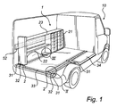
- Fig. 1 discloses an open-up perspective view of a service vehicle comprising a load securing system according to the invention.
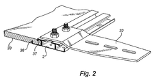
- Fig. 2 discloses an enlarged partial perspective view of the cut out II in fig. 1
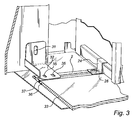
- Fig. 3. discloses an enlarged partial perspective view of the cut out III in fig. 1
- Fig. 4a discloses a rail according to a first embodiment.
- Fig. 4b discloses a rail according to a second embodiment.
- Fig. 5 discloses an enlarged partial perspective view of the cut-out V in fig. 1 (without module units)
- Fig. 6 disclosure a module system according to a third aspect of the invention as seen in perspective from behind.
- The above, as well as additional objects, features and advantages of the present invention, will be better understood through the following illustrative and nonlimiting detailed description of preferred embodiments of the present invention, with reference to the appended drawings, where the same reference numerals will be used for similar elements, wherein:
- Fig. 1 shows a
module system 1 for a cargo or a back space in a automotive vehicle, for example aservice vehicle 10.Module units 20, which can be adrawer unit 23 containing forexample drawers 21 orshelves 22, are placed and fixated (more clearly shown in Fig. 3) on an already installed inner floor construction. The floor construction contains afloor section 33 with arail 2 arranged on two opposite sides of thefloor section 33. Thefloor section 33 is fixed to therails 2. The rails are fixed to the service vehicle by fixingmeans 32 to thering fasteners 31. This arrangement provides for that the inner floor construction can be arranged to the ordinary floor without being damaged through holes or other interferences. Arail 52 is positioned along the longitudinal direction of the vehicle. Advantageously, it has the same shape as therail 2, which is arranged in the floor construction. As the floor construction preferable is used in the middle section of the vehicle (in between the rails) can alevelling section 34 for the free spaces be arranged on therail 2. - Fig 2. shows a section of a preferred floor construction in detail in a perspective view. The
floor section 33 shows afirst groove 36 and asecond groove 37. Therail 2 andfloor section 33 with itsgrooves - Fig. 3 shows another section of a preferred floor construction as described in Fig. 2 with a different kind of fixing means. The fixing means 32 has two fixing element holes 35 through which said fixing means can be fixated to the
rail 2 and it also shows a hole through which the whole floor construction may be fixed to the ring fastener in the vehicle. It also shows afastening bracket 2 which arrange the module unit through a rail fastening means 26 to therail 2. - Fig. 4a shows the
rail 2 in a perspective way with one kind of profile. This profile is made out of a sheet metal by e.g. roll forming but can also be an extruded profile. Therail 2 contains out of three rail sections, afirst rail section 11, asecond rail section 12 and athird rail section 13. Between these sections is a firstundercut profile 5 and a secondundercut profile 6. Thefirst rail section 11 has on its left side anfirst flange 3 and the third rail section has on it left side ansecond flange 7. The first and thethird rail section undercut profile second flange third rail section holes 4 shown. These are used to secure therail - Fig. 4b shows a slightly different profile. This profile can also be made out of a sheet metal or an extruded profile. The rail contains three rail sections, a
first rail section 111, asecond rail section 112 and athird rail section 113. Between these sections is a firstundercut profile 105 and a secondundercut profile 106. On the outer edges of the first and second undercut section profile edge 108 downwardly directed. This makes the interaction with thefloor section 33 better. Thefirst rail section 11 has on its left side afirst flange 103 and the third rail section has on it left side asecond flange 107. - Fig. 5 shows a
rail 52 which contains of three rail sections, afirst rail section 51, asecond rail section 60 and athird rail section 61. Between these sections is a firstundercut profile 55 and a secondundercut profile 56. Thefirst rail 51 has on its upward side anfirst flange 53 and thethird rail section 61 has on it downward side asecond flange 57. Between the first undercutprofile 55 and the secondundercut profile 56 wall brackets are arranged 59a, 59b and 59c, for being manoeuvrable along therail 52. - Fig 6. shows a module system with
module units 20 with attached wall-brackets rail 52 at an open end and the module units are installed in a suitable position by fixing brackets to the floor after. As an option the units are positioned one by one against prearranged brackets in therail 52 for accomplishing a fastening zone. The skilled person realises that there are also other ways utilizing the flexibility of the invention depending on the actual module unit to be installed. - The invention has mainly been described above with reference to a some embodiments. However, as is readily appreciated by a person skilled in the art, other embodiments than the ones disclosed above are equally possible within the scope of the invention, as defined by the appended patent claims.
Claims (20)
- Load securing system, for a cargo or a back
space in an automotive vehicle (10),
Characterised in that
at least two rails (2) are arranged fixed along the cargo space, wherein one side of one of said rails (2) is held by one or more fixing means (32) connected to a ring fastener (31) of the service vehicle (10) and the other rail is held in the opposite side by one or more fixing means (32) connected to a ring fastener (31), and said rails (2) are connected by a bridging element (33) in a space between said rails (2). - Load securing system according to claim 1, wherein said rails (2) are propagating parallel to one another along the longitudinal direction of the vehicle (10).
- Load securing system according to any one of claims 1-2, wherein at least one module system (1), containing for example work equipment, is placed along the longitudinal direction of the vehicle (10) and attached to one of said rails.
- Load securing system according to claim 3, wherein at a first side portion of the module system (1) a first fastener is arranged and at a second side portion of said module system a second fastener is arranged, said fasteners arranging the module system to the wall of the vehicle (10).
- Load securing system according to claim 3, wherein a rail (52) is positioned by said wall along the longitudinal direction of the vehicle (10) and comprises fastening zones (64) for the module system (1), said rail (52) being formed for variable positioning of at least three fasteners (59a, 59b, 59c) for distribution of module system loading along said rail (52).
- Load securing system according to claim 5, wherein at least one additional fastening zone (64b) is positioned between a first (64a) and a second (64c) fastening zone of the side portions of the module system (1).
- Load securing system according to any one of claims 1-6, wherein the rail (2) is made of metal.
- Load securing system according to any one of claims 1-7, wherein the rail (2) has at least one undercut profile (5; 6, 55; 56, 105; 106).
- Load securing system according to any one of claims 1-8, wherein the rail (2) has three rail sections (11, 12, 13; 51, 60, 61; 111, 112, 113).
- Load securing system according to any one of claims 1-9, wherein the rail (2) is adapted for tongue and groove engagement with said bridging element (33) along a first groove (36).
- Load securing system according to any one of claims 1-10, wherein the rail (2) is adapted for tongue and groove engagement with said bridging element (33) along a first (36) and a second groove (37).
- Load securing system according to any one of claims 1-11, wherein the bridging element (33) is a floor section.
- Load securing system according to any one of claims 1-12, wherein a plurality of floor elements forms the bridging element (33).
- Load securing system according to any one of claims 1-13, wherein the upper side of the bridging element (33) and the upper side of the rail (5, 6) is levelled once mounted.
- Load securing system according to any one of claims 1-14, wherein the bridging element (33) is made of wood or composite material.
- Load securing system according to any one of claims 1-15, wherein the bridging element (33) is provided with a mat on the upper side.
- Method of installing a load securing system in service vehicles comprising the steps of, connecting a bridging element (33) with a rail (2) on two sides of said bridging element (33),
placing bridging element (33) and rails (2) in a cargo space floor of said vehicle and arranging said rails (2) to the ring fasteners (31) on a side of the respective rail (2) facing away from said bridging element (33), thereby fixing said load securing system in the service vehicle (10) . - Method according to claim 17, in which additional floor levelling sections (34) are positioned on vehicle floor spaces in the cargo space, in order to achieve a levelled surface.
- Method according to any one of claims 17-18, in which a module system (1) is positioned anchored to said rail (2) of the load securing system.
- Method according to any one of claims 17-19, in which a module system (1) is fixed to a corresponding rail (52) mounted on the wall of the service vehicle (10).
Priority Applications (4)
| Application Number | Priority Date | Filing Date | Title |
|---|---|---|---|
| EP06119987A EP1894774B1 (en) | 2006-09-01 | 2006-09-01 | Load securing system and method for installing such system |
| DE602006018913T DE602006018913D1 (en) | 2006-09-01 | 2006-09-01 | Load securing system and corresponding installation method |
| AT06119987T ATE491598T1 (en) | 2006-09-01 | 2006-09-01 | LOAD SECURITY SYSTEM AND CORRESPONDING INSTALLATION PROCEDURE |
| PCT/EP2007/007482 WO2008025500A2 (en) | 2006-09-01 | 2007-08-27 | Load securing system and method for installing such system |
Applications Claiming Priority (1)
| Application Number | Priority Date | Filing Date | Title |
|---|---|---|---|
| EP06119987A EP1894774B1 (en) | 2006-09-01 | 2006-09-01 | Load securing system and method for installing such system |
Publications (2)
| Publication Number | Publication Date |
|---|---|
| EP1894774A1 true EP1894774A1 (en) | 2008-03-05 |
| EP1894774B1 EP1894774B1 (en) | 2010-12-15 |
Family
ID=37681681
Family Applications (1)
| Application Number | Title | Priority Date | Filing Date |
|---|---|---|---|
| EP06119987A Not-in-force EP1894774B1 (en) | 2006-09-01 | 2006-09-01 | Load securing system and method for installing such system |
Country Status (4)
| Country | Link |
|---|---|
| EP (1) | EP1894774B1 (en) |
| AT (1) | ATE491598T1 (en) |
| DE (1) | DE602006018913D1 (en) |
| WO (1) | WO2008025500A2 (en) |
Cited By (8)
| Publication number | Priority date | Publication date | Assignee | Title |
|---|---|---|---|---|
| EP2965948A1 (en) | 2014-07-09 | 2016-01-13 | Modul-System HH AB | A floor system, a vehicle, such as a service vehicle, comprising such a floor system and a method of installing such a floor system |
| EP3078577A1 (en) | 2015-04-09 | 2016-10-12 | Modul-System HH AB | A floor system, a vehicle, such as a service vehicle, comprising such a floor system |
| EP3078544A1 (en) | 2015-04-09 | 2016-10-12 | Modul-System HH AB | An elongated securing rail |
| EP3078578A1 (en) | 2015-04-09 | 2016-10-12 | Modul-System HH AB | A floor panel system |
| DE102015004337A1 (en) | 2015-04-09 | 2016-10-13 | Modul-System Hh Ab | Bottom plate portion |
| EP3106372A1 (en) | 2015-06-17 | 2016-12-21 | Modul-System HH AB | A floor panel system |
| WO2017009682A1 (en) * | 2015-07-16 | 2017-01-19 | Volvo Truck Corporation | Foldable storage arrangement |
| US20220314865A1 (en) * | 2021-04-06 | 2022-10-06 | Samuel Westlind | Motor vehicle deck |
Citations (2)
| Publication number | Priority date | Publication date | Assignee | Title |
|---|---|---|---|---|
| US3159111A (en) * | 1962-05-14 | 1964-12-01 | Puilman Inc | Container attachment device for railway cars |
| US6270137B1 (en) * | 2000-03-03 | 2001-08-07 | J.T. Custom Works Inc. | Track system for customized vehicles and trailers |
-
2006
- 2006-09-01 DE DE602006018913T patent/DE602006018913D1/en active Active
- 2006-09-01 EP EP06119987A patent/EP1894774B1/en not_active Not-in-force
- 2006-09-01 AT AT06119987T patent/ATE491598T1/en not_active IP Right Cessation
-
2007
- 2007-08-27 WO PCT/EP2007/007482 patent/WO2008025500A2/en active Application Filing
Patent Citations (2)
| Publication number | Priority date | Publication date | Assignee | Title |
|---|---|---|---|---|
| US3159111A (en) * | 1962-05-14 | 1964-12-01 | Puilman Inc | Container attachment device for railway cars |
| US6270137B1 (en) * | 2000-03-03 | 2001-08-07 | J.T. Custom Works Inc. | Track system for customized vehicles and trailers |
Cited By (12)
| Publication number | Priority date | Publication date | Assignee | Title |
|---|---|---|---|---|
| EP2965948A1 (en) | 2014-07-09 | 2016-01-13 | Modul-System HH AB | A floor system, a vehicle, such as a service vehicle, comprising such a floor system and a method of installing such a floor system |
| WO2016005162A1 (en) * | 2014-07-09 | 2016-01-14 | Modul-System Hh Ab | A floor system, a vehicle, such as a service vehicle, comprising such a floor system and a method of installing such a floor system |
| US10369938B2 (en) * | 2014-07-09 | 2019-08-06 | Modul-System Hh Ab | Floor system, a vehicle, such as a service vehicle, comprising such a floor system and a method of installing such a floor system |
| EP3078577A1 (en) | 2015-04-09 | 2016-10-12 | Modul-System HH AB | A floor system, a vehicle, such as a service vehicle, comprising such a floor system |
| EP3078544A1 (en) | 2015-04-09 | 2016-10-12 | Modul-System HH AB | An elongated securing rail |
| EP3078578A1 (en) | 2015-04-09 | 2016-10-12 | Modul-System HH AB | A floor panel system |
| DE102015004337A1 (en) | 2015-04-09 | 2016-10-13 | Modul-System Hh Ab | Bottom plate portion |
| CN107438539A (en) * | 2015-04-09 | 2017-12-05 | 魔组系统有限公司 | Bottom board system includes vehicle, such as service vehicle of such bottom board system |
| CN107438539B (en) * | 2015-04-09 | 2021-05-07 | 魔组系统有限公司 | Floor system, vehicle, such as a service vehicle, comprising such a floor system |
| EP3106372A1 (en) | 2015-06-17 | 2016-12-21 | Modul-System HH AB | A floor panel system |
| WO2017009682A1 (en) * | 2015-07-16 | 2017-01-19 | Volvo Truck Corporation | Foldable storage arrangement |
| US20220314865A1 (en) * | 2021-04-06 | 2022-10-06 | Samuel Westlind | Motor vehicle deck |
Also Published As
| Publication number | Publication date |
|---|---|
| ATE491598T1 (en) | 2011-01-15 |
| WO2008025500A2 (en) | 2008-03-06 |
| WO2008025500A3 (en) | 2008-04-17 |
| EP1894774B1 (en) | 2010-12-15 |
| DE602006018913D1 (en) | 2011-01-27 |
Similar Documents
| Publication | Publication Date | Title |
|---|---|---|
| EP1894774B1 (en) | Load securing system and method for installing such system | |
| EP1894773A1 (en) | Module system for service vehicles | |
| CA2816268C (en) | Rail mounting system | |
| EP2408648B1 (en) | Sunroof headliner attachment system | |
| EP3233568B1 (en) | A fastening system | |
| US20140248103A1 (en) | Loading rail and sliding block for a loading rail | |
| US8066316B2 (en) | Adjustable mounting system for vehicular body components | |
| KR20140034317A (en) | Holding device for an adjustment drive of a motor vehicle seat | |
| US10112549B2 (en) | Vehicle ladder mounting system for custom installations | |
| EP3166821B1 (en) | A floor system, a vehicle, such as a service vehicle, comprising such a floor system and a method of installing such a floor system | |
| EP3112212B1 (en) | Absorbing rail | |
| GB2512335A (en) | Roof rail system | |
| EP3078548B1 (en) | A storage system | |
| EP3078577B1 (en) | A floor system, a vehicle, such as a service vehicle, comprising such a floor system | |
| EP3106371B1 (en) | A floor system | |
| EP3106372A1 (en) | A floor panel system | |
| EP3078544A1 (en) | An elongated securing rail | |
| EP3078578A1 (en) | A floor panel system | |
| US20080143140A1 (en) | Hatch for a Commercial Vehicle |
Legal Events
| Date | Code | Title | Description |
|---|---|---|---|
| PUAI | Public reference made under article 153(3) epc to a published international application that has entered the european phase |
Free format text: ORIGINAL CODE: 0009012 |
|
| AK | Designated contracting states |
Kind code of ref document: A1 Designated state(s): AT BE BG CH CY CZ DE DK EE ES FI FR GB GR HU IE IS IT LI LT LU LV MC NL PL PT RO SE SI SK TR |
|
| AX | Request for extension of the european patent |
Extension state: AL BA HR MK YU |
|
| 17P | Request for examination filed |
Effective date: 20080902 |
|
| 17Q | First examination report despatched |
Effective date: 20081002 |
|
| AKX | Designation fees paid |
Designated state(s): AT BE BG CH CY CZ DE DK EE ES FI FR GB GR HU IE IS IT LI LT LU LV MC NL PL PT RO SE SI SK TR |
|
| GRAP | Despatch of communication of intention to grant a patent |
Free format text: ORIGINAL CODE: EPIDOSNIGR1 |
|
| GRAS | Grant fee paid |
Free format text: ORIGINAL CODE: EPIDOSNIGR3 |
|
| GRAA | (expected) grant |
Free format text: ORIGINAL CODE: 0009210 |
|
| AK | Designated contracting states |
Kind code of ref document: B1 Designated state(s): AT BE BG CH CY CZ DE DK EE ES FI FR GB GR HU IE IS IT LI LT LU LV MC NL PL PT RO SE SI SK TR |
|
| REG | Reference to a national code |
Ref country code: CH Ref legal event code: EP Ref country code: GB Ref legal event code: FG4D |
|
| REG | Reference to a national code |
Ref country code: IE Ref legal event code: FG4D |
|
| REF | Corresponds to: |
Ref document number: 602006018913 Country of ref document: DE Date of ref document: 20110127 Kind code of ref document: P |
|
| REG | Reference to a national code |
Ref country code: SE Ref legal event code: TRGR |
|
| REG | Reference to a national code |
Ref country code: NL Ref legal event code: VDEP Effective date: 20101215 |
|
| PG25 | Lapsed in a contracting state [announced via postgrant information from national office to epo] |
Ref country code: LT Free format text: LAPSE BECAUSE OF FAILURE TO SUBMIT A TRANSLATION OF THE DESCRIPTION OR TO PAY THE FEE WITHIN THE PRESCRIBED TIME-LIMIT Effective date: 20101215 |
|
| LTIE | Lt: invalidation of european patent or patent extension |
Effective date: 20101215 |
|
| PG25 | Lapsed in a contracting state [announced via postgrant information from national office to epo] |
Ref country code: BG Free format text: LAPSE BECAUSE OF FAILURE TO SUBMIT A TRANSLATION OF THE DESCRIPTION OR TO PAY THE FEE WITHIN THE PRESCRIBED TIME-LIMIT Effective date: 20110315 Ref country code: LV Free format text: LAPSE BECAUSE OF FAILURE TO SUBMIT A TRANSLATION OF THE DESCRIPTION OR TO PAY THE FEE WITHIN THE PRESCRIBED TIME-LIMIT Effective date: 20101215 Ref country code: FI Free format text: LAPSE BECAUSE OF FAILURE TO SUBMIT A TRANSLATION OF THE DESCRIPTION OR TO PAY THE FEE WITHIN THE PRESCRIBED TIME-LIMIT Effective date: 20101215 Ref country code: NL Free format text: LAPSE BECAUSE OF FAILURE TO SUBMIT A TRANSLATION OF THE DESCRIPTION OR TO PAY THE FEE WITHIN THE PRESCRIBED TIME-LIMIT Effective date: 20101215 Ref country code: CY Free format text: LAPSE BECAUSE OF FAILURE TO SUBMIT A TRANSLATION OF THE DESCRIPTION OR TO PAY THE FEE WITHIN THE PRESCRIBED TIME-LIMIT Effective date: 20101215 Ref country code: SI Free format text: LAPSE BECAUSE OF FAILURE TO SUBMIT A TRANSLATION OF THE DESCRIPTION OR TO PAY THE FEE WITHIN THE PRESCRIBED TIME-LIMIT Effective date: 20101215 Ref country code: AT Free format text: LAPSE BECAUSE OF FAILURE TO SUBMIT A TRANSLATION OF THE DESCRIPTION OR TO PAY THE FEE WITHIN THE PRESCRIBED TIME-LIMIT Effective date: 20101215 |
|
| PG25 | Lapsed in a contracting state [announced via postgrant information from national office to epo] |
Ref country code: EE Free format text: LAPSE BECAUSE OF FAILURE TO SUBMIT A TRANSLATION OF THE DESCRIPTION OR TO PAY THE FEE WITHIN THE PRESCRIBED TIME-LIMIT Effective date: 20101215 Ref country code: IS Free format text: LAPSE BECAUSE OF FAILURE TO SUBMIT A TRANSLATION OF THE DESCRIPTION OR TO PAY THE FEE WITHIN THE PRESCRIBED TIME-LIMIT Effective date: 20110415 Ref country code: CZ Free format text: LAPSE BECAUSE OF FAILURE TO SUBMIT A TRANSLATION OF THE DESCRIPTION OR TO PAY THE FEE WITHIN THE PRESCRIBED TIME-LIMIT Effective date: 20101215 Ref country code: ES Free format text: LAPSE BECAUSE OF FAILURE TO SUBMIT A TRANSLATION OF THE DESCRIPTION OR TO PAY THE FEE WITHIN THE PRESCRIBED TIME-LIMIT Effective date: 20110326 Ref country code: BE Free format text: LAPSE BECAUSE OF FAILURE TO SUBMIT A TRANSLATION OF THE DESCRIPTION OR TO PAY THE FEE WITHIN THE PRESCRIBED TIME-LIMIT Effective date: 20101215 Ref country code: PT Free format text: LAPSE BECAUSE OF FAILURE TO SUBMIT A TRANSLATION OF THE DESCRIPTION OR TO PAY THE FEE WITHIN THE PRESCRIBED TIME-LIMIT Effective date: 20110415 Ref country code: GR Free format text: LAPSE BECAUSE OF FAILURE TO SUBMIT A TRANSLATION OF THE DESCRIPTION OR TO PAY THE FEE WITHIN THE PRESCRIBED TIME-LIMIT Effective date: 20110316 |
|
| PG25 | Lapsed in a contracting state [announced via postgrant information from national office to epo] |
Ref country code: SK Free format text: LAPSE BECAUSE OF FAILURE TO SUBMIT A TRANSLATION OF THE DESCRIPTION OR TO PAY THE FEE WITHIN THE PRESCRIBED TIME-LIMIT Effective date: 20101215 Ref country code: PL Free format text: LAPSE BECAUSE OF FAILURE TO SUBMIT A TRANSLATION OF THE DESCRIPTION OR TO PAY THE FEE WITHIN THE PRESCRIBED TIME-LIMIT Effective date: 20101215 Ref country code: RO Free format text: LAPSE BECAUSE OF FAILURE TO SUBMIT A TRANSLATION OF THE DESCRIPTION OR TO PAY THE FEE WITHIN THE PRESCRIBED TIME-LIMIT Effective date: 20101215 |
|
| PLBE | No opposition filed within time limit |
Free format text: ORIGINAL CODE: 0009261 |
|
| STAA | Information on the status of an ep patent application or granted ep patent |
Free format text: STATUS: NO OPPOSITION FILED WITHIN TIME LIMIT |
|
| PG25 | Lapsed in a contracting state [announced via postgrant information from national office to epo] |
Ref country code: DK Free format text: LAPSE BECAUSE OF FAILURE TO SUBMIT A TRANSLATION OF THE DESCRIPTION OR TO PAY THE FEE WITHIN THE PRESCRIBED TIME-LIMIT Effective date: 20101215 |
|
| 26N | No opposition filed |
Effective date: 20110916 |
|
| PG25 | Lapsed in a contracting state [announced via postgrant information from national office to epo] |
Ref country code: IT Free format text: LAPSE BECAUSE OF FAILURE TO SUBMIT A TRANSLATION OF THE DESCRIPTION OR TO PAY THE FEE WITHIN THE PRESCRIBED TIME-LIMIT Effective date: 20101215 |
|
| REG | Reference to a national code |
Ref country code: DE Ref legal event code: R097 Ref document number: 602006018913 Country of ref document: DE Effective date: 20110916 |
|
| PG25 | Lapsed in a contracting state [announced via postgrant information from national office to epo] |
Ref country code: MC Free format text: LAPSE BECAUSE OF NON-PAYMENT OF DUE FEES Effective date: 20110930 |
|
| REG | Reference to a national code |
Ref country code: CH Ref legal event code: PL |
|
| REG | Reference to a national code |
Ref country code: IE Ref legal event code: MM4A |
|
| PG25 | Lapsed in a contracting state [announced via postgrant information from national office to epo] |
Ref country code: CH Free format text: LAPSE BECAUSE OF NON-PAYMENT OF DUE FEES Effective date: 20110930 Ref country code: IE Free format text: LAPSE BECAUSE OF NON-PAYMENT OF DUE FEES Effective date: 20110901 Ref country code: LI Free format text: LAPSE BECAUSE OF NON-PAYMENT OF DUE FEES Effective date: 20110930 |
|
| PG25 | Lapsed in a contracting state [announced via postgrant information from national office to epo] |
Ref country code: LU Free format text: LAPSE BECAUSE OF NON-PAYMENT OF DUE FEES Effective date: 20110901 |
|
| PG25 | Lapsed in a contracting state [announced via postgrant information from national office to epo] |
Ref country code: TR Free format text: LAPSE BECAUSE OF FAILURE TO SUBMIT A TRANSLATION OF THE DESCRIPTION OR TO PAY THE FEE WITHIN THE PRESCRIBED TIME-LIMIT Effective date: 20101215 |
|
| PG25 | Lapsed in a contracting state [announced via postgrant information from national office to epo] |
Ref country code: HU Free format text: LAPSE BECAUSE OF FAILURE TO SUBMIT A TRANSLATION OF THE DESCRIPTION OR TO PAY THE FEE WITHIN THE PRESCRIBED TIME-LIMIT Effective date: 20101215 |
|
| REG | Reference to a national code |
Ref country code: FR Ref legal event code: PLFP Year of fee payment: 11 |
|
| PGFP | Annual fee paid to national office [announced via postgrant information from national office to epo] |
Ref country code: GB Payment date: 20160920 Year of fee payment: 11 |
|
| PGFP | Annual fee paid to national office [announced via postgrant information from national office to epo] |
Ref country code: FR Payment date: 20160923 Year of fee payment: 11 |
|
| GBPC | Gb: european patent ceased through non-payment of renewal fee |
Effective date: 20170901 |
|
| REG | Reference to a national code |
Ref country code: FR Ref legal event code: ST Effective date: 20180531 |
|
| PG25 | Lapsed in a contracting state [announced via postgrant information from national office to epo] |
Ref country code: GB Free format text: LAPSE BECAUSE OF NON-PAYMENT OF DUE FEES Effective date: 20170901 |
|
| PG25 | Lapsed in a contracting state [announced via postgrant information from national office to epo] |
Ref country code: FR Free format text: LAPSE BECAUSE OF NON-PAYMENT OF DUE FEES Effective date: 20171002 |
|
| PGFP | Annual fee paid to national office [announced via postgrant information from national office to epo] |
Ref country code: SE Payment date: 20190815 Year of fee payment: 14 |
|
| PG25 | Lapsed in a contracting state [announced via postgrant information from national office to epo] |
Ref country code: SE Free format text: LAPSE BECAUSE OF NON-PAYMENT OF DUE FEES Effective date: 20200902 |
|
| REG | Reference to a national code |
Ref country code: SE Ref legal event code: EUG |
|
| PGFP | Annual fee paid to national office [announced via postgrant information from national office to epo] |
Ref country code: DE Payment date: 20210818 Year of fee payment: 16 |
|
| REG | Reference to a national code |
Ref country code: DE Ref legal event code: R119 Ref document number: 602006018913 Country of ref document: DE |
|
| PG25 | Lapsed in a contracting state [announced via postgrant information from national office to epo] |
Ref country code: DE Free format text: LAPSE BECAUSE OF NON-PAYMENT OF DUE FEES Effective date: 20230401 |