EP1894720A1 - Holding device - Google Patents
Holding device Download PDFInfo
- Publication number
- EP1894720A1 EP1894720A1 EP06757330A EP06757330A EP1894720A1 EP 1894720 A1 EP1894720 A1 EP 1894720A1 EP 06757330 A EP06757330 A EP 06757330A EP 06757330 A EP06757330 A EP 06757330A EP 1894720 A1 EP1894720 A1 EP 1894720A1
- Authority
- EP
- European Patent Office
- Prior art keywords
- plate
- end portion
- tension bar
- trailing edge
- edge end
- Prior art date
- Legal status (The legal status is an assumption and is not a legal conclusion. Google has not performed a legal analysis and makes no representation as to the accuracy of the status listed.)
- Withdrawn
Links
- 230000007246 mechanism Effects 0.000 claims abstract description 16
- 238000003780 insertion Methods 0.000 claims abstract description 4
- 230000037431 insertion Effects 0.000 claims abstract description 4
- 230000014759 maintenance of location Effects 0.000 abstract description 2
- 238000005549 size reduction Methods 0.000 abstract description 2
- 238000000034 method Methods 0.000 description 3
- 230000008859 change Effects 0.000 description 2
- 239000002184 metal Substances 0.000 description 2
- 239000000853 adhesive Substances 0.000 description 1
- 230000001070 adhesive effect Effects 0.000 description 1
- 230000009194 climbing Effects 0.000 description 1
- 238000007796 conventional method Methods 0.000 description 1
- 230000003247 decreasing effect Effects 0.000 description 1
- 238000009434 installation Methods 0.000 description 1
- 239000000463 material Substances 0.000 description 1
- 238000012986 modification Methods 0.000 description 1
- 230000004048 modification Effects 0.000 description 1
Images






Classifications
-
- B—PERFORMING OPERATIONS; TRANSPORTING
- B41—PRINTING; LINING MACHINES; TYPEWRITERS; STAMPS
- B41F—PRINTING MACHINES OR PRESSES
- B41F27/00—Devices for attaching printing elements or formes to supports
- B41F27/12—Devices for attaching printing elements or formes to supports for attaching flexible printing formes
- B41F27/1218—Devices for attaching printing elements or formes to supports for attaching flexible printing formes comprising printing plate tensioning devices
- B41F27/125—Devices for attaching printing elements or formes to supports for attaching flexible printing formes comprising printing plate tensioning devices moving in the printing plate end on a curvilinear path, e.g. by winding on a roll
-
- B—PERFORMING OPERATIONS; TRANSPORTING
- B41—PRINTING; LINING MACHINES; TYPEWRITERS; STAMPS
- B41F—PRINTING MACHINES OR PRESSES
- B41F27/00—Devices for attaching printing elements or formes to supports
- B41F27/12—Devices for attaching printing elements or formes to supports for attaching flexible printing formes
- B41F27/1206—Feeding to or removing from the forme cylinder
-
- B—PERFORMING OPERATIONS; TRANSPORTING
- B41—PRINTING; LINING MACHINES; TYPEWRITERS; STAMPS
- B41F—PRINTING MACHINES OR PRESSES
- B41F27/00—Devices for attaching printing elements or formes to supports
- B41F27/12—Devices for attaching printing elements or formes to supports for attaching flexible printing formes
- B41F27/1262—Devices for attaching printing elements or formes to supports for attaching flexible printing formes without tensioning means
Definitions
- the present invention relates to a holding apparatus for holding a plate on a circumferential surface of a holder, and more particularly to a holding apparatus suitable for use in the retention of a plate on a circumferential surface of a sleeve of a plate cylinder of a printing machine.
- the Patent Document 1 discloses a plate holding apparatus designed such that a leaf spring for engaging a trailing edge end portion of a plate is provided along an axial direction of a tension bar and a lever fixedly secured onto an axial end portion of the tension bar is moved by a spring so as to rotate the tension bar so that the trailing edge end portion of the plate is drawn into a slit of a plate cylinder by the leaf spring to hold the plate on a circumferential surface of the plate cylinder.
- Patent Document 2 discloses a plate holding apparatus designed such that a leaf spring for engaging a trailing edge end portion of a plate is provided along an axial direction of a tension bar as well as the Patent Document 1 and a lever fixedly secured onto an axial end portion of the tension bar is moved by use of a working cylinder instead of a spring so as to rotate the tension bar so that the trailing edge end portion of the plate is drawn into a slit of a plate cylinder by the leaf spring to hold the plate on a circumferential surface of the plate cylinder.
- the present invention has been developed in consideration of such problems, and it is an object of the invention to a holding apparatus suitable particularly for a plate cylinder sleeve having a small thickness and capable of decreasing the size of the apparatus.
- the rotating mechanism is capable of selecting a rotational phase position of the tension bar from any one of positions which are a mounting position at which the trailing edge end portion is set in the groove section, a fastening position at which the trailing edge end portion is drawn into the groove section and the plate is fastened onto the circumferential surface of the holder, and a withdrawing position at which the trailing edge endportion is released from the interior of the groove section.
- the tension bar preferably has a hook for engaging the trailing edge end portion of the plate. This enables the trailing edge end portion of the plate to be fixedly hooked by the hook of the tension bar, which prevents the trailing edge end portion from getting out of place during the mounting operation for the plate, thereby facilitating the plate mounting operation.
- the rotating mechanism has a torsion spring biasing the tension bar in a direction of drawing the trailing edge end portion of the plate into the groove section and, at the fastening position, the tension bar is further rotatable by a predetermined quantity in a direction of drawing the plate thereinto.
- the torsion spring is mounted on each of both end portions of the tension bar.
- the rotating force is applied to both the end portions of the tension bar, which can reduce the torsion of the tension bar.
- the holder is composed of a cylindrical sleeve. This allows the installation on the cylindrical sleeve and, hence, the attachment/detachment of the plate can be made in a state where the cylindrical sleeve is detached from the holder, which improves the working efficiency.
- the hole section into which the tension bar is inserted and fitted can be equipped with the rotating mechanism, which can achieve the size reduction of the apparatus and which can hold the plate (for example, printing plate, metal blanket) reliably.
- FIGs . 1 to 13 are illustrations for explaining a holding apparatus according to an embodiment of the present invention.
- FIG. 1 is a structural view showing an essential part thereof
- FIG. 2 is a perspective view showing a plate cylinder
- FIG. 3 is a cross-sectional view showing a plate cylinder taken along an axial direction of the plate cylinder
- FIG. 4 is a cross-sectional view taken along Z-Z of FIG. 3
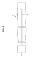
- FIG. 5 is an illustration viewed from a direction A of an arrow in FIG. 4
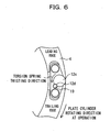
- FIG. 6 is a side-elevational illustration of an essential part viewed from an operation side
- FIG. 1 is a structural view showing an essential part thereof
- FIG. 2 is a perspective view showing a plate cylinder
- FIG. 3 is a cross-sectional view showing a plate cylinder taken along an axial direction of the plate cylinder
- FIG. 4 is a cross-sectional view taken along Z-Z of FIG. 3
- FIG. 5 is an illustration viewed from a direction A of
- FIG. 7 is a side-elevational illustration of an essential part viewed from a drive side
- FIG. 8 is a cross-sectional view taken along S-S of FIG. 7
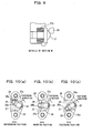
- FIG. 9 is a detailed illustration of a section M of FIG. 8
- FIGs. 10(a) to 10(c) are illustrations for explaining operations of a rotating mechanism
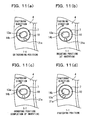
- FIGs. 11 (a) to 11 (d) are cross-sectional views taken along T-T of FIG. 1
- FIGs. 12 (a) to 12(d) are cross-sectional views taken along P-P of FIG. 1
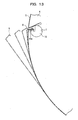
- FIG. 13 is an illustration for explaining an operation of a plate at the attachment of the plate.
- a holding apparatus 1 is provided on a printing cylinder (although a printing machine has a plate cylinder and a blanket cylinder, the following description will be given as an example about a plate cylinder) 2.
- the plate cylinder 2 is composed of a support 3 and a cylindrical plate cylinder sleeve (holder; which will hereinafter be referred to simply as sleeve) 4 mounted on a circumferential surface of the support 3, and the sleeve 4 having a different thickness is mounted on the support 3, which enables a free change of the diameter of the plate cylinder 2.
- the thickness of the sleeve 4 is, for example, as very thin as approximately 20 mm, since this holding apparatus 1 is designed to be considerably more compact in comparison with a conventional holding apparatus as mentioned later, this holding apparatus 1 can easily be placed on such a small-thickness sleeve 4.
- the plate (flexible plate; in the case of a blanket cylinder, a blanket sheet such as a metal blanket) 5 is mounted on a circumferential surface of the sleeve 4 in a state wound thereon through the use of this holding apparatus 1.
- this holding apparatus 1 is provided on the sleeve 4, it is also possible that this holding apparatus 1 is directly placed on a plate cylinder which does not employ the sleeve 4 (that is, plate itself which is of a type having no sleeve).
- the sleeve 4 is, on an inner circumferential surface thereof, equipped with an elastic body (not shown) having a diameter slightly smaller than an outer diameter of the support 3.
- the elastic body is expanded by applying high-pressure air from an outer circumferential surface of the support 3 toward the diameter outside and the sleeve 4 is inserted in an axial direction of the support 3.
- the supply of the high-pressure air is stopped to reduce the diameter of the elastic body so that the sleeve 4 is fixedly secured onto the outer circumferential surface of the support 3.
- this holding apparatus 1 has a hole section 7 made along an axial direction of the interior of the sleeve 4, a tension bar 10 inserted and fitted into the hole section 7 and a rotating mechanism 11 located in the hole section 7 for rotating the tension bar 10.
- this holding apparatus 1 has a groove section 8 formed by making a notch in the circumferential surface of the sleeve 4 along an axial direction and connected to the hole section 7, with a leading edge end portion (one edge) and trailing edge end portion (another edge) (see FIG. 12 ) of the plate 5 being inserted into this groove section 8.
- the tension bar 10 is located at a generally central portion of the hole section 7 in the axial direction, and the tension bar 10 is equipped with an hook 10a [for example, see FIG. 12 (a) ] for engaging the trailing edge end portion of the plate 5.
- the rotating mechanism 11 is designed to select a rotational phase position of the tension bar 10 from any one of mounting positions at which the trailing edge end portion of the plate 5 is mounted in the groove section 8, a fastening position at which the trailing edge end portion of the plate 5 is drawn into the groove section 8 and the plate 5 is fastened onto the circumferential surface of the sleeve 4 and a withdrawing position at which the trailing edge end portion is released from the interior of the groove section 8.
- a first supporting shaft 12 is located at an operation side (one end portion) of the tension bar 10.
- a drive side end portion 12a of the first supporting shaft 12 is inserted and fitted into an engaging hole 14a made in an operation side end portion of the tension bar 10 to be rotatable and slidable.
- a torsion spring (first torsion spring) 16 is provided to be wound around an outer circumference of the first supporting shaft 12.
- a drive side end portion 16a of the torsion spring 16 is inserted and fitted into a spring engaging hole 15a, made in the operation side end portion of the tension bar 10, to be stopped in a state engaged therewith, while an operation side end portion 16b of the torsion spring 16 is inserted and fitted into a spring engaging hole 17, made in an operation side end portion 12b of the first supporting shaft 12, to be stopped in a state engaged therewith.
- a first handle (first operating portion) 12c is made on the operation side end portion 12b of the first supporting shaft 12.
- the first handle 12c protrudes from the hole section 7 of the sleeve 4 toward the operation side exterior, and when the first handle 12c is rotated in a direction (plate fastening direction) that the trailing edge end portion of the plate 5 is drawn into the groove section 8 by means of the tension bar 10, the torsion spring 16 can be twisted so as to bias the tension bar 10 in the aforesaid plate drawing direction.
- the first supporting shaft 12 and the tension bar 10 are no restraint upon each other in the shaft rotating direction, at the assembling, difficulty is encountered in previously applying torsion to the torsion spring 16 between the first supporting shaft 12 and the tension bar 10. Accordingly, after the assembling of the tension bar 10, the torsion spring 16 and the first supporting shaft 12, the first handle 12c is rotated to apply a biasing force so that the torsion spring 16 is biased in the plate drawing direction.
- a cavity portion 12d is made in the first handle 12c and, when the first handle 12c is rotated in the plate drawing direction and fixed at a predetermined position in a state where the stopper 19 is engaged with this cavity portion 12d, a predetermined torsion force (torque) develops in the torsion spring 16, which allows a predetermined biasing force to be applied to the tension bar 10 in the aforesaid plate drawing direction.
- a wrench mounting hole 20 is made in the first handle 12c and, for rotating the first handle 12c to twist the torsion spring 16, it is possible to turn a wrench in a state where the wrench is mounted in the wrench mounting hole 20.
- a second supporting shaft 13 is located on a drive side (the other end portion) of the tension bar 10.
- An operation side end portion 13a of the second supporting shaft 13 is inserted and fitted into an engaging hole 14b made in the drive side end portion of the tension bar 10.
- the engaging hole 14b made in the drive side end portion of the tension bar 10 is formed into an elliptic (oval) configuration, for example, as shown in FIG. 11(a) and the operation side end portion 13a of the second supporting shaft 13 is also formed into a generally elliptic configuration, and a minute gap is made between an inner wall of the engaging hole 14b and the operation side end portion 13a of the second supporting shaft 13.
- a torsion spring (second torsion spring) 21 is provided in a state wound around the outer circumference of the second supporting shaft 13 as shown in FIG. 1 . Still moreover, an operation side end portion 21a of the torsion spring 21 is inserted and fitted into a spring hole 15b, made in a drive side end portion of the tension bar 10, to be stopped in a state engaged therewith, and a drive side end portion 21b of the torsion spring 21 twisted by a predetermined quantity in the plate drawing direction is inserted and fitted into a spring engaging hole 22, made in a drive side end portion 13b of the second supporting shaft 13, to be stopped in a state engaged therewith.
- the torsion spring 21 can be twisted in advance so as to exhibit a biasing force.
- a second handle (second operating portion) 13c is produced on the drive side end portion 13b of the second supporting shaft 13.
- the second handle 13c protrudes from the hole section 7 of the sleeve 4 toward the drive side exterior, and the rotational phase position of the tension bar 10 is adjustable by rotating this second handle 13c.
- a wrench mounting hole 24 is also made in the second handle 13c and, when the tension bar 10 is rotated at the attachment/detachment of the plate 5, it is rotated in a state where a wrench is mounted in this wrench mounting hole 24.
- a stopper 25 is inserted and fitted into the drive side end portion 13b of the second supporting shaft 13 in a direction perpendicular to the second supporting shaft 13.
- the stopper 25 is fixedly secured to the second supporting shaft 13 and, when the second handle 13c is rotated in the plate fastening direction or in the plate withdrawing direction as shown in FIG. 7 , it is rotated integrally with the second supporting shaft 13.
- plunger pins 26 and 27 are planted on the operation side with respect to the stopper 25, and the plunger pins 26 and 27 are made to come into contact with an operation side surface of the stopper 25 by means of belleville springs 26a and 27a, respectively.
- FIGs. 10(a) to 10(c) three cavity portions 25a, 25b and 25c are made in the operation side surface of the stopper 25, and these cavity portions 25a, 25b and 25c are properly engaged with the plunger pins 26 and 27, thereby enabling the second handle 13c to be fixed at three positions of a withdrawing position of the plate 5 (position where the trailing edge end portion of the plate 5 is released from the hook 10a of the tension bar 10 and detached from the groove section 8 of the sleeve 4) shown in FIG. 10(a) , a mounting position of the plate 5 (position where the trailing edge end portion of the plate 5 is stopped in a state engaged with the hook 10a of the tension bar 10) shown in FIG.
- the withdrawing position of the plate 5 corresponds to the case in which the cavity portion 25b of the stopper 25 is engaged with the plunger pin 26 as shown in FIG. 10(a)
- the mounting position of the plate 5 corresponds to a case in which, as shown in FIG. 10 (b) , the cavity portion 25a of the stopper 25 is engaged with the plunger pin 26 and the cavity portion 25c of the stopper 25 is engaged with the plunger pin 27, and the fastening position of the plate 5 corresponds to a case in which the cavity portion 25b of the stopper 25 is engaged with the plunger pin 27 as shown in FIG. 10(c) .
- a restriction wall 28 restricts the stopper 25 so as to prevent the stopper 25 from further rotating in a direction opposite to the fastening direction at the withdrawing position of the plate 5, and a restriction wall 29 restricts the stopper 25 so as to prevent the stopper 25 from further rotating in the fastening direction at the fastening position of the plate 5.
- the tension bar 10 is rotated in the plate 5 fastening direction according to this shifting, so the trailing edge end portion of the plate 5 can be drawn into the groove section 8 of the sleeve 4, which can prevent the plate 5 from becoming loose, thereby reliably fastening the plate 5 onto the circumferential surface of the sleeve 4.
- the holding apparatus 1 is configured as described above, and the attachment and detachment of the plate 5 on and from the circumferential surface of the sleeve 4 are made as follows. First of all, as shown in FIG. 12(b) , the leading edge end portion of the plate 5 is inserted into the groove section 8 of the sleeve 4 and the plate 5 is wound around on the circumferential surface of the sleeve 4 and the trailing edge end portion of the plate 5 is inserted into the groove section 8 of the sleeve 4. At this time, the second handle 13c is operated so that the stopper 25 comes to the mounting position shown in FIG. 10 (b) , and the hook 10a of the tension bar 10 is placed at a position shown in FIG.
- the second handle 13c (see FIG. 7 ) is rotated in the fastening direction so that the stopper 25 reaches the fastening position shown in FIG. 10(c) , and the hook 10a of the tension bar 10 is rotated to the position shown in FIG. 12(d) so that the trailing edge end portion of the plate 5 is drawn into the groove section 8 of the sleeve 4.
- the second handle 13c (see FIG. 7 ) is rotated in a direction (plate withdrawing direction) opposite to the fastening direction so that the stopper 25 reaches the withdrawing position shown in FIG.
- the hook 10a of the tension bar 10 is rotated to the position shown in FIG. 12(a) to detach the trailing edge end portion of the plate 5 from the hook 10a of the tension bar 10.
- the plate 5 springs out from the groove section 8 of the sleeve 4 by means of elastic force. This allows the plate 5 to be easily pulled out from the groove 8 of the sleeve 4.
- this holding apparatus 1 has a configuration in which the rotating mechanism 11 together with the tension bar 10 is incorporated into the hole section 7 of the sleeve 4, which allows the apparatus to be more compact and enables the apparatus to be provided even in the sleeve 4 having, for example, a thickness of approximately 20 mm like this embodiment.
- a rotating force is applied to the tension bar 10 by means of the torsion springs 16 and 21 placed on the both the end portions of the tension bar 10 in the axial directions thereof, it is possible to apply uniform biasing forces to both the end portions of the tension bar 10, which can reduce the torsion of the tension bar 10.
- this holding apparatus 1 employs a manner that the plate 5 is held in a state hooked by the hook 10a of the tension bar 10 as shown in FIG. 12(d) , thereby allowing the reuse without damaging the plate 5.
Landscapes
- Engineering & Computer Science (AREA)
- Mechanical Engineering (AREA)
- Supply, Installation And Extraction Of Printed Sheets Or Plates (AREA)
Abstract
The present invention relates to a holding apparatus which is made to hold a flexible plate wound on a circumferential surface of a holder and more particularly to a holding apparatus suitable for use in the retention of a plate on a circumferential surface of a sleeve of a plate cylinder of a printing machine. A holding apparatus 1 made to hold a plate 5 on a circumferential surface of a holder 4 for the apparatus size reduction comprises a hole section 7 made in the holder along an axial direction of the holder 4, a groove section 8 made by notching the circumferential surface of the holder 4 along the axial direction to establish a connection with the hole section 7 and accept insertion of a leading edge end portion and trailing edge end portion of the plate 5, a tension bar 10 inserted and fitted into the hole section 7 for engaging the trailing edge end portion of the plate 5 and a rotating mechanism 11 provided in the hole section 7 for rotating the tension bar 10.
Description
- The present invention relates to a holding apparatus for holding a plate on a circumferential surface of a holder, and more particularly to a holding apparatus suitable for use in the retention of a plate on a circumferential surface of a sleeve of a plate cylinder of a printing machine.
- So far, there have been developed various types of plate holding apparatus which is for holding a plate on a plate cylinder of a printing machine. For example, the
Patent Document 1 discloses a plate holding apparatus designed such that a leaf spring for engaging a trailing edge end portion of a plate is provided along an axial direction of a tension bar and a lever fixedly secured onto an axial end portion of the tension bar is moved by a spring so as to rotate the tension bar so that the trailing edge end portion of the plate is drawn into a slit of a plate cylinder by the leaf spring to hold the plate on a circumferential surface of the plate cylinder. - In addition, the
Patent Document 2 discloses a plate holding apparatus designed such that a leaf spring for engaging a trailing edge end portion of a plate is provided along an axial direction of a tension bar as well as thePatent Document 1 and a lever fixedly secured onto an axial end portion of the tension bar is moved by use of a working cylinder instead of a spring so as to rotate the tension bar so that the trailing edge end portion of the plate is drawn into a slit of a plate cylinder by the leaf spring to hold the plate on a circumferential surface of the plate cylinder. - Patent Document 1 :
Japanese Utility Model Laid-Open No. HEI 4-7133 - Patent Document 2 :
Japanese Patent Laid-Open No. 2000-301694 - However, in the case of the above-mentioned
Patent Documents Patent Documents - The present invention has been developed in consideration of such problems, and it is an object of the invention to a holding apparatus suitable particularly for a plate cylinder sleeve having a small thickness and capable of decreasing the size of the apparatus.
- For solving the above-mentioned problems, a holding apparatus according to the present invention, which is made to hold a flexible plate wound on a circumferential surface of a holder comprises a hole section formed in the holder along an axial direction of the holder, a groove section formed on the circumferential surface of the holder along the axial direction to connect with the hole section for accepting insertion of one edge as a leading edge end portion and another edge as a trailing edge end portion of the plate, a tension bar inserted and fitted into the hole section for engaging the trailing edge end portion of the plate, and a rotating mechanismprovided in the hole section for rotating the tension bar.
- In addition, preferably, the rotating mechanism is capable of selecting a rotational phase position of the tension bar from any one of positions which are a mounting position at which the trailing edge end portion is set in the groove section, a fastening position at which the trailing edge end portion is drawn into the groove section and the plate is fastened onto the circumferential surface of the holder, and a withdrawing position at which the trailing edge endportion is released from the interior of the groove section.
This enables the rotational phase position of the tension bar to be selected to one of the mounting position, the fastening position and the withdrawing position, which allows easy attachment/detachment of the plate. Thus, one person can easily carry out the operation for the attachment and detachment of the plate. - Still additionally, the tension bar preferably has a hook for engaging the trailing edge end portion of the plate.
This enables the trailing edge end portion of the plate to be fixedly hooked by the hook of the tension bar, which prevents the trailing edge end portion from getting out of place during the mounting operation for the plate, thereby facilitating the plate mounting operation.
Yet additionally, preferably, the rotating mechanism has a torsion spring biasing the tension bar in a direction of drawing the trailing edge end portion of the plate into the groove section and, at the fastening position, the tension bar is further rotatable by a predetermined quantity in a direction of drawing the plate thereinto.
Thus, even if the plate lengthens and the trailing edge end portion of the plate shifts, the tension bar is rotated according to this shifting, so the trailing edge end portion of the plate can always be drawn into the groove section, which can prevent the plate from becoming loose, thereby reliably fixedly securing the plate onto the circumferential surface of the holder. - Moreover, preferably, the torsion spring is mounted on each of both end portions of the tension bar.
Thus, the rotating force is applied to both the end portions of the tension bar, which can reduce the torsion of the tension bar. - Still moreover, preferably, the holder is composed of a cylindrical sleeve.
This allows the installation on the cylindrical sleeve and, hence, the attachment/detachment of the plate can be made in a state where the cylindrical sleeve is detached from the holder, which improves the working efficiency. - With the holding apparatus according to the present invention, the hole section into which the tension bar is inserted and fitted can be equipped with the rotating mechanism, which can achieve the size reduction of the apparatus and which can hold the plate (for example, printing plate, metal blanket) reliably.
-
- [
FIG. 1 ] is a structural view showing an essential part of a holding apparatus according to an embodiment of the present invention. - [
FIG. 2 ] is a perspective view showing a plate cylinder according to an embodiment of the present invention. - [
FIG. 3 ] is a cross-sectional view showing a plate cylinder taken along an axial direction of the plate cylinder according to an embodiment of the present invention. - [
FIG. 4 ] is a cross-sectional view taken along Z-Z ofFIG. 3 . - [
FIG. 5 ] is an illustration viewed from a direction A of an arrow inFIG. 4 . - [
FIG. 6 ] is a side-elevational illustration of an essential part of a holding apparatus according to an embodiment of the present invention viewed from an operation side. - [
FIG. 7 ] is a side-elevational illustration of an essential part of a holding apparatus according to an embodiment of the present invention viewed from a drive side. - [
FIG. 8 ] is a cross-sectional view taken along S-S ofFIG. 7 . - [
FIG. 9 ] is a detailed illustration of a section M ofFIG. 8 . - [
FIGs. 10] FIGs. 10 (a), 10 (b) and 10 (c) are illustrations for explaining operations of a rotating mechanism. - [
FIGs. 11] FIGs. 11(a), 11(b), 11(c) and 11(d) are cross-sectional views taken along T-T ofFIG. 1 . - [
FIGs. 12] FIGs. 12(a), 12(b), 12(c) and 12(d) are cross-sectional views taken along P-P ofFIG. 1 . - [
FIG. 13 ] is an illustration for explaining an operation of a plate at the attachment/detachment of the plate. Description of Reference Numerals -
- 1
- holding apparatus
- 2
- plate cylinder
- 3
- support
- 4
- sleeve (holder)
- 5
- plate (flexible plate)
- 7
- hole section
- 8
- groove section (slit)
- 10
- tension bar
- 10a
- hook
- 11
- rotating mechanism
- 12
- first supporting shaft
- 12a
- drive side end portion of first supporting shaft
- 12b
- operation side end portion of first supporting shaft
- 12c
- first handle
- 12d
- cavity portion
- 13
- second supporting shaft
- 13a
- operation side end portion of second supporting shaft
- 13b
- drive side end portion of second supporting shaft
- 13c
- second handle
- 14a
- engaging hole made in an operation side end portion of tension bar
- 14b
- spring engaging hole made in an operation side end portion of tension bar
- 14b
- engaging hole made in a drive side end portion of tension bar
- 15b
- spring engaging hole made in a drive side end portion of tension bar
- 16
- torsion spring
- 16a
- drive side end portion of torsion spring
- 16b
- operation side end portion of torsion spring
- 17
- spring engaging hole made in an operation side end portion of first supporting shaft
- 19
- stopper
- 20
- wrench mounting hole
- 21
- torsion spring.
- 21a
- operation side end portion of torsion spring
- 21b
- drive side end portion of torsion spring
- 22
- spring engaging hole made in a drive side end portion of second supporting shaft
- 24
- wrench mounting hole
- 25
- stopper
- 25a, 25b, 25c
- cavity portion
- 26, 27
- plunger pin
- 26a, 27a
- belleville spring
- 28, 29
- restriction wall
- Referring to the drawings, a description will be given hereinbelow of an embodiment of the present invention.
FIGs . 1 to 13 are illustrations for explaining a holding apparatus according to an embodiment of the present invention.FIG. 1 is a structural view showing an essential part thereof,FIG. 2 is a perspective view showing a plate cylinder,FIG. 3 is a cross-sectional view showing a plate cylinder taken along an axial direction of the plate cylinder,FIG. 4 is a cross-sectional view taken along Z-Z ofFIG. 3 ,FIG. 5 is an illustration viewed from a direction A of an arrow inFIG. 4 ,FIG. 6 is a side-elevational illustration of an essential part viewed from an operation side,FIG. 7 is a side-elevational illustration of an essential part viewed from a drive side,FIG. 8 is a cross-sectional view taken along S-S ofFIG. 7 ,FIG. 9 is a detailed illustration of a section M ofFIG. 8 ,FIGs. 10(a) to 10(c) are illustrations for explaining operations of a rotating mechanism,FIGs. 11 (a) to 11 (d) are cross-sectional views taken along T-T ofFIG. 1 ,FIGs. 12 (a) to 12(d) are cross-sectional views taken along P-P ofFIG. 1 , andFIG. 13 is an illustration for explaining an operation of a plate at the attachment of the plate. - As shown in
FIGs . 2 and3 , a holdingapparatus 1 according to this embodiment is provided on a printing cylinder (although a printing machine has a plate cylinder and a blanket cylinder, the following description will be given as an example about a plate cylinder) 2. In this case, theplate cylinder 2 is composed of asupport 3 and a cylindrical plate cylinder sleeve (holder; which will hereinafter be referred to simply as sleeve) 4 mounted on a circumferential surface of thesupport 3, and thesleeve 4 having a different thickness is mounted on thesupport 3, which enables a free change of the diameter of theplate cylinder 2. Although the thickness of thesleeve 4 is, for example, as very thin as approximately 20 mm, since this holdingapparatus 1 is designed to be considerably more compact in comparison with a conventional holding apparatus as mentioned later, this holdingapparatus 1 can easily be placed on such a small-thickness sleeve 4. Moreover, as shown inFIG. 2 , the plate (flexible plate; in the case of a blanket cylinder, a blanket sheet such as a metal blanket) 5 is mounted on a circumferential surface of thesleeve 4 in a state wound thereon through the use of this holdingapparatus 1. Although the following description will be given with respect to an example in which thisholding apparatus 1 is provided on thesleeve 4, it is also possible that this holdingapparatus 1 is directly placed on a plate cylinder which does not employ the sleeve 4 (that is, plate itself which is of a type having no sleeve). Still moreover, thesleeve 4 is, on an inner circumferential surface thereof, equipped with an elastic body (not shown) having a diameter slightly smaller than an outer diameter of thesupport 3. At the attachment of the sleeve, the elastic body is expanded by applying high-pressure air from an outer circumferential surface of thesupport 3 toward the diameter outside and thesleeve 4 is inserted in an axial direction of thesupport 3. After the insertion of thesleeve 4, the supply of the high-pressure air is stopped to reduce the diameter of the elastic body so that thesleeve 4 is fixedly secured onto the outer circumferential surface of thesupport 3. - As shown in
FIG, 1 , this holdingapparatus 1 has ahole section 7 made along an axial direction of the interior of thesleeve 4, atension bar 10 inserted and fitted into thehole section 7 and arotating mechanism 11 located in thehole section 7 for rotating thetension bar 10. Moreover, as shown inFIGs. 4 and5 , this holdingapparatus 1 has agroove section 8 formed by making a notch in the circumferential surface of thesleeve 4 along an axial direction and connected to thehole section 7, with a leading edge end portion (one edge) and trailing edge end portion (another edge) (seeFIG. 12 ) of theplate 5 being inserted into thisgroove section 8. - As shown in
FIG, 1 , thetension bar 10 is located at a generally central portion of thehole section 7 in the axial direction, and thetension bar 10 is equipped with anhook 10a [for example, seeFIG. 12 (a) ] for engaging the trailing edge end portion of theplate 5. Moreover, the rotatingmechanism 11 is designed to select a rotational phase position of thetension bar 10 from any one of mounting positions at which the trailing edge end portion of theplate 5 is mounted in thegroove section 8, a fastening position at which the trailing edge end portion of theplate 5 is drawn into thegroove section 8 and theplate 5 is fastened onto the circumferential surface of thesleeve 4 and a withdrawing position at which the trailing edge end portion is released from the interior of thegroove section 8. - With reference to
FIG. 1 , a concrete description will be given of therotating mechanism 11. A first supportingshaft 12 is located at an operation side (one end portion) of thetension bar 10. A driveside end portion 12a of the first supportingshaft 12 is inserted and fitted into anengaging hole 14a made in an operation side end portion of thetension bar 10 to be rotatable and slidable. Moreover, a torsion spring (first torsion spring) 16 is provided to be wound around an outer circumference of the first supportingshaft 12. Still moreover, a driveside end portion 16a of thetorsion spring 16 is inserted and fitted into aspring engaging hole 15a, made in the operation side end portion of thetension bar 10, to be stopped in a state engaged therewith, while an operationside end portion 16b of thetorsion spring 16 is inserted and fitted into aspring engaging hole 17, made in an operationside end portion 12b of the first supportingshaft 12, to be stopped in a state engaged therewith. - In addition, a first handle (first operating portion) 12c is made on the operation
side end portion 12b of the first supportingshaft 12. Thefirst handle 12c protrudes from thehole section 7 of thesleeve 4 toward the operation side exterior, and when thefirst handle 12c is rotated in a direction (plate fastening direction) that the trailing edge end portion of theplate 5 is drawn into thegroove section 8 by means of thetension bar 10, thetorsion spring 16 can be twisted so as to bias thetension bar 10 in the aforesaid plate drawing direction. - That is, since the first supporting
shaft 12 and thetension bar 10 are no restraint upon each other in the shaft rotating direction, at the assembling, difficulty is encountered in previously applying torsion to thetorsion spring 16 between the first supportingshaft 12 and thetension bar 10. Accordingly, after the assembling of thetension bar 10, thetorsion spring 16 and the first supportingshaft 12, thefirst handle 12c is rotated to apply a biasing force so that thetorsion spring 16 is biased in the plate drawing direction. - Thus, as shown in
FIG. 6 , acavity portion 12d is made in thefirst handle 12c and, when thefirst handle 12c is rotated in the plate drawing direction and fixed at a predetermined position in a state where thestopper 19 is engaged with thiscavity portion 12d, a predetermined torsion force (torque) develops in thetorsion spring 16, which allows a predetermined biasing force to be applied to thetension bar 10 in the aforesaid plate drawing direction. Moreover, as shown inFIG. 1 , awrench mounting hole 20 is made in thefirst handle 12c and, for rotating thefirst handle 12c to twist thetorsion spring 16, it is possible to turn a wrench in a state where the wrench is mounted in thewrench mounting hole 20. Incidentally, if the operation of thefirst handle 12c is conducted at a stage after the assembling, basically, there is no need to conduct the further operation, and thetorsion spring 16 can exhibit a predetermined biasing force. - On the other hand, a second supporting
shaft 13 is located on a drive side (the other end portion) of thetension bar 10. An operationside end portion 13a of the second supportingshaft 13 is inserted and fitted into an engaginghole 14b made in the drive side end portion of thetension bar 10. The engaginghole 14b made in the drive side end portion of thetension bar 10 is formed into an elliptic (oval) configuration, for example, as shown inFIG. 11(a) and the operationside end portion 13a of the second supportingshaft 13 is also formed into a generally elliptic configuration, and a minute gap is made between an inner wall of theengaging hole 14b and the operationside end portion 13a of the second supportingshaft 13. Moreover, a torsion spring (second torsion spring) 21 is provided in a state wound around the outer circumference of the second supportingshaft 13 as shown inFIG. 1 . Still moreover, an operationside end portion 21a of thetorsion spring 21 is inserted and fitted into aspring hole 15b, made in a drive side end portion of thetension bar 10, to be stopped in a state engaged therewith, and a driveside end portion 21b of thetorsion spring 21 twisted by a predetermined quantity in the plate drawing direction is inserted and fitted into aspring engaging hole 22, made in a driveside end portion 13b of the second supportingshaft 13, to be stopped in a state engaged therewith. In this connection, since the relative rotation of the second supportingshaft 13 with respect to thetension bar 10 is limited to within a predetermined range, at the assembling of the second supportingshaft 13 and thetension bar 10, thetorsion spring 21 can be twisted in advance so as to exhibit a biasing force. - In addition, a second handle (second operating portion) 13c is produced on the drive
side end portion 13b of the second supportingshaft 13. Thesecond handle 13c protrudes from thehole section 7 of thesleeve 4 toward the drive side exterior, and the rotational phase position of thetension bar 10 is adjustable by rotating thissecond handle 13c. Still additionally, awrench mounting hole 24 is also made in thesecond handle 13c and, when thetension bar 10 is rotated at the attachment/detachment of theplate 5, it is rotated in a state where a wrench is mounted in thiswrench mounting hole 24. - Yet additionally, as shown in
FIGs . 1 and7 , astopper 25 is inserted and fitted into the driveside end portion 13b of the second supportingshaft 13 in a direction perpendicular to the second supportingshaft 13. Thestopper 25 is fixedly secured to the second supportingshaft 13 and, when thesecond handle 13c is rotated in the plate fastening direction or in the plate withdrawing direction as shown inFIG. 7 , it is rotated integrally with the second supportingshaft 13.
Furthermore, as shown inFIGs . 7 ,8 and9 , plunger pins 26 and 27 are planted on the operation side with respect to thestopper 25, and the plunger pins 26 and 27 are made to come into contact with an operation side surface of thestopper 25 by means of belleville springs 26a and 27a, respectively. - Still furthermore, as shown in
FIGs. 10(a) to 10(c) , threecavity portions stopper 25, and thesecavity portions second handle 13c to be fixed at three positions of a withdrawing position of the plate 5 (position where the trailing edge end portion of theplate 5 is released from thehook 10a of thetension bar 10 and detached from thegroove section 8 of the sleeve 4) shown inFIG. 10(a) , a mounting position of the plate 5 (position where the trailing edge end portion of theplate 5 is stopped in a state engaged with thehook 10a of the tension bar 10) shown inFIG. 10(b) and a fastening position of the plate 5 (position where the trailing edge end portion of theplate 5 is drawn into thegroove section 8 of thesleeve 4 by thehook 10a of thetension bar 10 and theplate 5 is fastened onto a circumferential surface of thesleeve 4. - In this case, the withdrawing position of the
plate 5 corresponds to the case in which thecavity portion 25b of thestopper 25 is engaged with theplunger pin 26 as shown inFIG. 10(a) , and the mounting position of theplate 5 corresponds to a case in which, as shown inFIG. 10 (b) , thecavity portion 25a of thestopper 25 is engaged with theplunger pin 26 and thecavity portion 25c of thestopper 25 is engaged with theplunger pin 27, and the fastening position of theplate 5 corresponds to a case in which thecavity portion 25b of thestopper 25 is engaged with theplunger pin 27 as shown inFIG. 10(c) . Arestriction wall 28 restricts thestopper 25 so as to prevent thestopper 25 from further rotating in a direction opposite to the fastening direction at the withdrawing position of theplate 5, and arestriction wall 29 restricts thestopper 25 so as to prevent thestopper 25 from further rotating in the fastening direction at the fastening position of theplate 5. - Yet furthermore, as shown in
FIGs. 11 (a) to 11 (d) , since thetension bar 10 is biased in the fastening direction of theplate 5 by means of thetorsion spring 16 and thetorsion spring 21, when the operationside end portion 13a of the second supportingshaft 13 is shifted in the order of the withdrawing position of theplate 5, the mounting position thereof and the fastening position thereof, in a state where the engaginghole 14b of thetension bar 10 is brought into contact with the operationside end portion 13a of the second supportingshaft 13, thetension bar 10 follows the rotation of the operationside end portion 13a of the second supportingshaft 13 and is rotated in theplate 5 fastening direction. - As mentioned above, a space exists between the operation
side end portion 13a of the second supportingshaft 13 and theengaging hole 14b of thetension bar 10 and, while the operationside end portion 13a of the second supportingshaft 13 is rotated from theplate 5 mounting position shown inFIG. 11 (c) up to theplate 5 fastening position shown inFIG. 11(d) , even if thetension bar 10 cannot be further rotated because thetension bar 10 falls into a trailing edge end portion fastening state, the operationside end portion 13a of the second supportingshaft 13 is rotated up to theplate 5 fastening position shown inFIG. 11 (d) . Thus, as shown inFIG. 12(d) , it is possible that the trailing edge end portion of theplate 5 is reliably drawn into thegroove section 8 of thesleeve 4 so as to fasten theplate 5 onto the circumferential surface of thesleeve 4. - In addition, when the operation
side end portion 13a of the second supportingshaft 13 is at theplate 5 fastening position shown inFIG. 11(d) , a space (clearance) whereby thetension bar 10 is further rotatable by a predetermined quantity in theplate 5 fastening direction is defined between the operationside end portion 13a of the second supportingshaft 13 and theengaging hole 14b of thetension bar 10. Thus, even if theplate 5 lengthens after the plate fastening and the trailing edge end portion of theplate 5 shifts, thetension bar 10 is rotated in theplate 5 fastening direction according to this shifting, so the trailing edge end portion of theplate 5 can be drawn into thegroove section 8 of thesleeve 4, which can prevent theplate 5 from becoming loose, thereby reliably fastening theplate 5 onto the circumferential surface of thesleeve 4. - The holding
apparatus 1 according to an embodiment of the present invention is configured as described above, and the attachment and detachment of theplate 5 on and from the circumferential surface of thesleeve 4 are made as follows.
First of all, as shown inFIG. 12(b) , the leading edge end portion of theplate 5 is inserted into thegroove section 8 of thesleeve 4 and theplate 5 is wound around on the circumferential surface of thesleeve 4 and the trailing edge end portion of theplate 5 is inserted into thegroove section 8 of thesleeve 4. At this time, thesecond handle 13c is operated so that thestopper 25 comes to the mounting position shown inFIG. 10 (b) , and thehook 10a of thetension bar 10 is placed at a position shown inFIG. 12 (b) . In this state, the trailing edge end portion of theplate 5 is inserted into thegroove section 8 of thesleeve 4 so as to draw an involute curve as shown inFIG. 13 , and a curved tip portion of the trailing edge end portion of theplate 5 is hooked by thehook 10a of thetension bar 10 while climbing over thehook 10a thereof. Thus, the trailing edge end portion of theplate 5 can be hooked by thehook 10a of thetension bar 10 and fixed as shown inFIG. 12(c) only by pushing the trailing edge end portion of theplate 5 into thegroove section 8 of thesleeve 4, so the trailing edge end portion of theplate 5 does not get out of place during theplate 5 mounting operation, thereby facilitating theplate 5 mounting operation. The leading edge end portion of theplate 5 is held and fixed between an inner wall of thegroove section 8 of thesleeve 4 and an circumferential surface of thetension bar 10. - Following this, the
second handle 13c (seeFIG. 7 ) is rotated in the fastening direction so that thestopper 25 reaches the fastening position shown inFIG. 10(c) , and thehook 10a of thetension bar 10 is rotated to the position shown inFIG. 12(d) so that the trailing edge end portion of theplate 5 is drawn into thegroove section 8 of thesleeve 4. Thus, it is possible to easily and reliably fasten theplate 5 onto the circumferential surface of thesleeve 4.
Moreover, at the detachment of theplate 5, thesecond handle 13c (seeFIG. 7 ) is rotated in a direction (plate withdrawing direction) opposite to the fastening direction so that thestopper 25 reaches the withdrawing position shown inFIG. 10(a) , and thehook 10a of thetension bar 10 is rotated to the position shown inFIG. 12(a) to detach the trailing edge end portion of theplate 5 from thehook 10a of thetension bar 10. At this time, theplate 5 springs out from thegroove section 8 of thesleeve 4 by means of elastic force. This allows theplate 5 to be easily pulled out from thegroove 8 of thesleeve 4. - As described above, this holding
apparatus 1 has a configuration in which therotating mechanism 11 together with thetension bar 10 is incorporated into thehole section 7 of thesleeve 4, which allows the apparatus to be more compact and enables the apparatus to be provided even in thesleeve 4 having, for example, a thickness of approximately 20 mm like this embodiment.
In addition, since a rotating force is applied to thetension bar 10 by means of the torsion springs 16 and 21 placed on the both the end portions of thetension bar 10 in the axial directions thereof, it is possible to apply uniform biasing forces to both the end portions of thetension bar 10, which can reduce the torsion of thetension bar 10. - Still additionally, as shown in
FIG. 12(c) , when the trailing edge end portion of theplate 5 is inserted into thegroove section 8 of thesleeve 4, by pushing the trailing edge end portion of theplate 5 thereinto, the trailing edge end portion of theplate 5 climbs over thehook 10a of thetension bar 10 and is hooked by thehook 10a of thetension bar 10, so the trailing edge end portion of theplate 5 does not depart from thehook 10a of thetension bar 10 even if it is released from hands thereafter.
Yet additionally, the positioning mechanism composed of thestopper 25 and the plunger pins 26 and 27 shown inFIGs. 10(a) to 10(c) can easily set thetension bar 10 at three positions of the withdrawing position, the mounting position and the fastening position. Therefore, one person can easily conduct the operations for the attachment and detachment of a plate. - Moreover, difficulty was so far experienced in mounting a leaf spring on a tension bar, whereas this holding
apparatus 1 does not require a conventional leaf spring, thereby facilitating the apparatus assembling. Still moreover, according to conventional techniques, there is a possibility that difficulty is encountered in drawing a plate in a case in which a tip portion of a leaf spring and a trailing edge end portion of the plate do not accurately engage with each other, whereas this holdingapparatus 1 can eliminate such a possibility.
Still moreover, as a technique of mounting a plate on a circumferential surface of a sleeve, for example, there has been known a technique in which, like a general flexo printing, a plate is directly adhered through an adhesive material to a circumferential surface of a sleeve. However, such an adhesion makes it difficult to reuse the plate because the plate is damaged when peeled off. On the other hand, this holdingapparatus 1 employs a manner that theplate 5 is held in a state hooked by thehook 10a of thetension bar 10 as shown inFIG. 12(d) , thereby allowing the reuse without damaging theplate 5. - Although the embodiment of the present invention has been described above, the present invention is not limited to the above-described embodiment, and it covers all changes and modifications of the embodiment of the invention herein which do not constitute departures from the spirit and scope of the invention.
Claims (6)
- A holding apparatus which is made to hold a flexible plate wound on a circumferential surface of a holder comprising:a hole section formed in the holder along an axial direction of the holder;a groove section formed on the circumferential surface of the holder along the axial direction to connect with said hole section for accepting insertion of one edge as a leading edge end portion and another edge as a trailing edge end portion of the plate;a tension bar inserted and fitted into said hole section for engaging the trailing edge end portion of the plate; anda rotating mechanism provided in said hole section for rotating said tension bar..
- The holding apparatus according to claim 1, wherein
said rotating mechanism being capable of selecting a rotational phase position of said tension bar from any one of positions which are
a mounting position at which the trailing edge end portion is set in said groove section,
a fastening position at which the trailing edge end portion is drawn into said groove section and the plate is fastened onto the circumferential surface of the holder, and
a withdrawing position at which the trailing edge end portion is released from the interior of said groove section. - The holding apparatus according to claim 1 or 2, wherein
said tension bar having a hook for engaging the trailing edge end portion of the plate. - The holding apparatus according to claim 2 or 3, wherein
said rotating mechanism having a torsion spring biasing said tension bar in a direction of drawing the trailing edge end portion of the plate into said groove section and, at the fastening position, said tension bar is further rotatable by a predetermined quantity in a direction of drawing the plate thereinto. - The holding apparatus according to claim 4, wherein
the torsion spring being mounted on each of both end portions of said tension bar. - A holding apparatus according to any one of claims 1 to 5, wherein
the holder being a cylindrical sleeve.
Applications Claiming Priority (2)
| Application Number | Priority Date | Filing Date | Title |
|---|---|---|---|
| JP2005185605A JP4699106B2 (en) | 2005-06-24 | 2005-06-24 | Holding device |
| PCT/JP2006/311982 WO2006137313A1 (en) | 2005-06-24 | 2006-06-15 | Holding device |
Publications (1)
| Publication Number | Publication Date |
|---|---|
| EP1894720A1 true EP1894720A1 (en) | 2008-03-05 |
Family
ID=37570343
Family Applications (1)
| Application Number | Title | Priority Date | Filing Date |
|---|---|---|---|
| EP06757330A Withdrawn EP1894720A1 (en) | 2005-06-24 | 2006-06-15 | Holding device |
Country Status (6)
| Country | Link |
|---|---|
| US (1) | US7730835B2 (en) |
| EP (1) | EP1894720A1 (en) |
| JP (1) | JP4699106B2 (en) |
| CN (1) | CN101198471B (en) |
| TW (1) | TW200706377A (en) |
| WO (1) | WO2006137313A1 (en) |
Cited By (1)
| Publication number | Priority date | Publication date | Assignee | Title |
|---|---|---|---|---|
| WO2014124649A1 (en) * | 2013-02-18 | 2014-08-21 | Tresu A/S | Anti bouncing printing roller/sleeve |
Families Citing this family (4)
| Publication number | Priority date | Publication date | Assignee | Title |
|---|---|---|---|---|
| JP2009196269A (en) * | 2008-02-22 | 2009-09-03 | Mitsubishi Heavy Ind Ltd | Rotary printing machine |
| WO2013042104A1 (en) * | 2011-09-25 | 2013-03-28 | Hewlett Packard Indigo B.V. | Blanket tensioning device |
| US10188096B1 (en) * | 2016-11-22 | 2019-01-29 | Paul Edwin Inskeep | Device for gripping and removing a bait station |
| CN108705862B (en) * | 2018-07-31 | 2023-12-19 | 贵州贤俊龙彩印有限公司 | Novel plate cylinder |
Family Cites Families (13)
| Publication number | Priority date | Publication date | Assignee | Title |
|---|---|---|---|---|
| US3382799A (en) * | 1966-07-29 | 1968-05-14 | Cottrell Company | Plate lockup means for offset or wraparound printing presses |
| JPH0526373A (en) | 1991-07-22 | 1993-02-02 | Sekisui Chem Co Ltd | Instrument for connecting pipes |
| JP2517106Y2 (en) * | 1991-09-12 | 1996-11-13 | 株式会社東京機械製作所 | Plate mounting device |
| JP2616902B2 (en) * | 1993-09-03 | 1997-06-04 | 株式会社東京機械製作所 | Plate mounting aid |
| JP2562413B2 (en) * | 1993-11-04 | 1996-12-11 | 株式会社東京機械製作所 | Plate mounting device in plate cylinder |
| JPH1120131A (en) * | 1997-07-03 | 1999-01-26 | Ryobi Ltd | Press plate gripper for printer |
| EP1038672B1 (en) | 1999-03-26 | 2003-12-03 | Heidelberger Druckmaschinen Aktiengesellschaft | Device for tensioning of printing plates in lock-up gaps having a reduced size |
| JP3461487B2 (en) * | 2000-07-06 | 2003-10-27 | 株式会社東京機械製作所 | Printing cylinder mounting device, printing plate and blanket |
| JP3446122B2 (en) * | 2000-07-12 | 2003-09-16 | 株式会社東京機械製作所 | Blanket torso |
| DE10218474A1 (en) * | 2002-04-25 | 2003-11-20 | Koenig & Bauer Ag | Devices for fastening at least one elevator on a cylinder of a rotary printing press and a printing unit with this device |
| JP2004074526A (en) * | 2002-06-21 | 2004-03-11 | Mitsubishi Heavy Ind Ltd | Sleeve for plate cylinder |
| US6796233B2 (en) * | 2002-11-20 | 2004-09-28 | Heidelberger Druckmaschinen Ag | Plate cylinder with splined shell |
| DE10324330A1 (en) * | 2003-05-27 | 2004-12-30 | Man Roland Druckmaschinen Ag | Plate cylinder of a printing press |
-
2005
- 2005-06-24 JP JP2005185605A patent/JP4699106B2/en not_active Expired - Fee Related
-
2006
- 2006-06-15 US US11/920,147 patent/US7730835B2/en not_active Expired - Fee Related
- 2006-06-15 WO PCT/JP2006/311982 patent/WO2006137313A1/en not_active Ceased
- 2006-06-15 CN CN2006800216688A patent/CN101198471B/en not_active Expired - Fee Related
- 2006-06-15 EP EP06757330A patent/EP1894720A1/en not_active Withdrawn
- 2006-06-19 TW TW095121937A patent/TW200706377A/en unknown
Non-Patent Citations (1)
| Title |
|---|
| See references of WO2006137313A1 * |
Cited By (2)
| Publication number | Priority date | Publication date | Assignee | Title |
|---|---|---|---|---|
| WO2014124649A1 (en) * | 2013-02-18 | 2014-08-21 | Tresu A/S | Anti bouncing printing roller/sleeve |
| US10011106B2 (en) | 2013-02-18 | 2018-07-03 | Tresu A/S | Anti-bouncing printing roller/sleeve |
Also Published As
| Publication number | Publication date |
|---|---|
| JP4699106B2 (en) | 2011-06-08 |
| JP2007001204A (en) | 2007-01-11 |
| US20090120314A1 (en) | 2009-05-14 |
| CN101198471A (en) | 2008-06-11 |
| US7730835B2 (en) | 2010-06-08 |
| TW200706377A (en) | 2007-02-16 |
| CN101198471B (en) | 2010-05-19 |
| WO2006137313A1 (en) | 2006-12-28 |
Similar Documents
| Publication | Publication Date | Title |
|---|---|---|
| US6913430B2 (en) | Board anchor | |
| JP2004239059A (en) | Door hinge, removable door check device, and method for arranging it on vehicle door hinge | |
| US7730835B2 (en) | Holding apparatus for holding a flexible plate on a circumferential surface of a holder of a printing machine | |
| US11008193B2 (en) | Drive shaft for reusable paper core | |
| JP4417830B2 (en) | Screen printer and screen cylinder | |
| EP1170124B1 (en) | Tensioning device for attaching a cover to a cylinder of a printing press | |
| JPH0724843U (en) | Winding mechanism for strips | |
| CN100496998C (en) | Mounting structure of binding tool for folder | |
| JP4522100B2 (en) | Tube attachment / detachment device | |
| JP3563795B2 (en) | Roll-shaped recording paper and a movable flange rotatably supporting the roll-shaped recording paper | |
| JPH02103148A (en) | Plate clamping apparatus | |
| US7831172B2 (en) | Pin driver | |
| JP2000176853A (en) | Jig for fastening the expanding rivet | |
| EP1086813A2 (en) | Blanket-mounting mechanism of printing press, and blanket | |
| JP2006175736A (en) | Plate clamping device, printing cylinder equipped therewith and plate-like member | |
| JP4716343B2 (en) | Bearing mechanism | |
| JP2006315152A (en) | Work drive device for cylindrical grinder | |
| JP2008247506A (en) | Bobbin attachment / detachment device | |
| JP4632969B2 (en) | Ribbon take-up reel | |
| JP2575399Y2 (en) | Chucking structure of winding core | |
| US6792659B1 (en) | Transmission tool | |
| JP2025067817A (en) | Valve core turning tool | |
| JP2007038324A (en) | E-type retaining ring attachment / detachment tool | |
| JPH10101253A (en) | Winding shaft | |
| JP2599828B2 (en) | Rotary shaft support device |
Legal Events
| Date | Code | Title | Description |
|---|---|---|---|
| PUAI | Public reference made under article 153(3) epc to a published international application that has entered the european phase |
Free format text: ORIGINAL CODE: 0009012 |
|
| 17P | Request for examination filed |
Effective date: 20071129 |
|
| AK | Designated contracting states |
Kind code of ref document: A1 Designated state(s): DE |
|
| DAX | Request for extension of the european patent (deleted) | ||
| DAX | Request for extension of the european patent (deleted) | ||
| RBV | Designated contracting states (corrected) |
Designated state(s): DE |
|
| RAP1 | Party data changed (applicant data changed or rights of an application transferred) |
Owner name: MITSUBISHI HEAVY INDUSTRIES PRINTING & PACKING MAC |
|
| RAP1 | Party data changed (applicant data changed or rights of an application transferred) |
Owner name: MITSUBISHI HEAVY INDUSTRIES PRINTING & PACKAGING M |
|
| STAA | Information on the status of an ep patent application or granted ep patent |
Free format text: STATUS: THE APPLICATION HAS BEEN WITHDRAWN |
|
| 18W | Application withdrawn |
Effective date: 20101221 |