EP1894674A1 - Sander - Google Patents
Sander Download PDFInfo
- Publication number
- EP1894674A1 EP1894674A1 EP07016863A EP07016863A EP1894674A1 EP 1894674 A1 EP1894674 A1 EP 1894674A1 EP 07016863 A EP07016863 A EP 07016863A EP 07016863 A EP07016863 A EP 07016863A EP 1894674 A1 EP1894674 A1 EP 1894674A1
- Authority
- EP
- European Patent Office
- Prior art keywords
- receptacle
- foot
- main body
- base
- disposed
- Prior art date
- Legal status (The legal status is an assumption and is not a legal conclusion. Google has not performed a legal analysis and makes no representation as to the accuracy of the status listed.)
- Granted
Links
Images

Classifications
-
- B—PERFORMING OPERATIONS; TRANSPORTING
- B24—GRINDING; POLISHING
- B24B—MACHINES, DEVICES, OR PROCESSES FOR GRINDING OR POLISHING; DRESSING OR CONDITIONING OF ABRADING SURFACES; FEEDING OF GRINDING, POLISHING, OR LAPPING AGENTS
- B24B55/00—Safety devices for grinding or polishing machines; Accessories fitted to grinding or polishing machines for keeping tools or parts of the machine in good working condition
- B24B55/04—Protective covers for the grinding wheel
- B24B55/05—Protective covers for the grinding wheel specially designed for portable grinding machines
- B24B55/055—Protective covers for the grinding wheel specially designed for portable grinding machines with oscillating tools
-
- B—PERFORMING OPERATIONS; TRANSPORTING
- B24—GRINDING; POLISHING
- B24B—MACHINES, DEVICES, OR PROCESSES FOR GRINDING OR POLISHING; DRESSING OR CONDITIONING OF ABRADING SURFACES; FEEDING OF GRINDING, POLISHING, OR LAPPING AGENTS
- B24B23/00—Portable grinding machines, e.g. hand-guided; Accessories therefor
- B24B23/04—Portable grinding machines, e.g. hand-guided; Accessories therefor with oscillating grinding tools; Accessories therefor
Definitions
- the present invention relates to a sander including a main body provided with a motor, and a base which is disposed below the main body and makes orbital motion according to rotation of the motor.
- an output shaft is projected to the lower side of the main body having a motor, and the base is eccentrically joined to the output shaft to cause the base to make an orbital motion (eccentric motion) according to rotation of the output shaft in response to driving of the motor, and an object material can be sanded with a sanding paper stretched on the bottom surface of the base.
- receptacles are formed on the main body and the base, respectively, so as to face each other, and between the receptacles, feet are laid.
- the feet are integrally molded from an elastic material such as rubber in many cases, however, its durability lowers due to heating and wearing.
- Japanese Patent No. 3634995 discloses a foot including a metallic foot body and elastic members (for example, an O-ring).
- the elastic members are disposed in the receptacles to support upper and lower ends in the axial direction of the foot body.
- Japanese Utility Model Publication No. 51-3988U teaches to provide a flexible dustproof cover so as to cover the entire region for providing the foot between the main body and the base.
- the above-described dustproof cover is made of a thin flexible material which has almost no rigidity, so that its upper and lower ends must be attached by screws, etc., to the opposing surfaces of the main body and the base, respectively.
- the attaching portions if gaps are left on the attaching portions, dust may enter from these portions. Therefore, to maintain the sealing performance of the attaching portions, flat attaching surfaces must be provided on the main body and the base, and this limits the shapes of the main body and the base.
- a sander comprising:
- the elastic sleeve may have a length longer than an interval between a lower edge of the first receptacle and an upper edge of the second receptacle.
- An upper edge of the elastic sleeve may be in press contact with the lower edge of the first receptacle, and a lower edge of the elastic sleeve may be in press contact with the upper edge of the second receptacle.
- the elastic sleeve may be comprised of sponge.
- the foot body may be comprised of aluminum.
- a sander comprising:
- the elastic sleeve may have a length longer than an interval between the lower surface of the main body and the upper surface of the base. An upper edge of the elastic sleeve may be in press contact with the lower surface of the main body, and a lower edge of the elastic sleeve may be in press contact with the upper surface of the base.
- the elastic sleeve may be comprised of sponge.
- the foot body may be comprised of aluminum.
- Fig. 1 shows a finishing sander 1 according to a first embodiment of the invention.
- the finishing sander 1 includes a main body 2 and a base 13 provided below the main body.
- the main body 2 is formed by half-divided housings 3 and 4 adapted to be divided vertically into two pieces.
- a motor 5 is housed in the main body 2 such that an output shaft 6 thereof is directed downward.
- the output shaft 6 is axially supported by ball bearings 7 that projects to the lower side of the main body 2.
- a cooling fan 8 is orthogonally secured to the output shaft 6 above the ball bearings 7.
- a dust collecting fan 9 is orthogonally secured to the output shaft 6 below the ball bearings 7.
- the dust collecting fan 9 is operable to suck dust from the lower side of the main body 2 and to feed the dust to a dust collecting nozzle 10 provided in a side portion of the main body 2.
- the reference numeral 11 denotes a handle extended at the upper side of the main body 2, and the reference numeral 12 denotes a switch lever.
- a bearing box 15 for housing ball bearings 14 is formed, and by inserting the output shaft 6 of the motor 5 into an eccentric hole 17 of an eccentric sleeve 16 axially supported by the ball bearings 14 the output shaft 6 at an eccentric position via an eccentric sleeve 16 is axially supported.
- the reference numerals 18 and 19 are a flat washer and a flat head screw as a stopper for the eccentric sleeve 16, and the reference numeral 20 denotes a balancer projected from an eccentric side of the eccentric sleeve 15.
- the reference numeral 21 is a pad provided on the lower surface of the base 13, and on its front and rear sides, clampers 22 are provided, respectively, and on the bottom surface of the pad 21, a sanding paper that is not shown can be stretched thereon.
- the reference numerals 23 denote feet laid between the main body 2 and the base 13 and include foot bodies 24 that have columnar shapes and are made of aluminum and rubber O-rings 26, respectively.
- the O-rings 26 are housed in the receptacles 27 recessed in the main body 2 and the base 13, respectively, so as to face each other, the O-rings are externally fitted to small diameter portions 25 projected from the centers of both ends of the foot bodies 24, whereby the O-rings 26 are pressurized to elastically support the foot bodies 24 in the axial direction thereof.
- the small diameter portions 25 have length that does not exceed the outermost ends of the O-rings 26 in the axial direction thereof, respectively.
- sponge sleeves 28 serving as elastic members are fitted onto the outer peripheries of the foot bodies 24, respectively.
- the sponge sleeve 28 is a cylindrical member slightly longer in the axial direction than the vertical interval between the upper and lower receptacles 27.
- the upper and lower ends come into pressure contact with the opening edges of the receptacles 27, respectively, and deform according to the opening edge shapes, whereby closing a gap between the receptacles 27.
- the finishing sander 1 constructed as described above, when the switch lever 12 is pushed down to drive the motor 5, the output shaft 6 rotates, however, the ball bearings 14 on the base 13 side axially support the output shaft 6 at an eccentric position via the eccentric sleeve 16, so that according to rotation of the output shaft 6, the base 13 makes orbital motion (eccentric motion) around the center of axis of the output shaft 6. Due to this orbital motion of the base 13, it becomes possible to sand an object material with a sanding paper stretched on the bottom surface of the base 13.
- the foot 23 makes so-called precession in that the lower end held by the receptacle 27 on the base 13 side makes a circular motion following the base 13 around a pivot set on the upper end held by the receptacle 27 on the main body 2 side, and acts to restrict rotation of the base 13 itself and prevent vertical vibration of the base 13.
- the sponge sleeve 28 is fitted onto the outer periphery of the foot 23 so as to close a gap between the receptacles 27, there is no possibility that dust caused by sanding enters the inside of the receptacles 27 from the portions between the foot body 24 and the receptacles 27.
- the sponge sleeve 28 is elastic, even when the foot 23 makes precession, the contact portion with the receptacle 27 deforms following the receptacle 27 and a closely-fitted state is maintained.
- the sponge sleeve 28 is fitted onto the outer periphery of each foot 23, its resistance against the base'13 making orbital motion is very small, so that it does not influence the sanding performance of the finishing sander 1 itself.
- the foot body 24 is comprised of aluminum, it is high in rigidity and can effectively prevent vertical flopping of the base 13, and also brings about a heat radiation effect.
- both ends of the foot body 24 are elastically supported by the O-rings 26, both ends of the foot body 24 become free ends and smoothly make precession.
- only a compression force acts on the O-ring 26 itself, and no shearing force or bending force is applied thereto, wearing is reduced. That is, the vibration isolating effect for the base 13 can be improved by effectively opposing this to axial vibration, and this contributes to the realization of smooth orbital motion of the base 13.
- the finishing sander 1 of the first embodiment by fitting a sponge sleeve 28 onto the outer periphery of the foot body 24 so as to cover the exposed portion of the foot body 24 and by bringing the upper and lower ends thereof into pressure contact with opening edges of the receptacles 27 so as to close a gap between the receptacles 27, high dust proofness is attained in each foot 23. Therefore, the foot bodies 24, the O-rings 26, and the receptacles 27 are prevented from being worn by dust.
- the above effect can be attained with the simple construction in which the sponge sleeve 28 is fitted onto the outer periphery of each foot 23, and special shape change for securing dust proofness or members for attaching the sponge sleeve 28 become unnecessary on the main body 2 and the base 13 including the receptacles. Therefore, a cost increase is minimized, and the shapes of the main body 2 and the base 13 are not limited.
- a sponge sleeve 29 is not fitted onto the outer periphery of each foot 23, but is interposed between the main body 2 and the base 13 so as to surround the entire region in which the feet 23 are provided. That is, the sponge sleeve 29 is a large cylindrical member formed along the outer contour of the lower surface of the main body 2.
- the sponge sleeve 29 is slightly longer in the axial direction than the vertical interval between the main body 2 and the base 13, and the upper end is brought into pressure contact with the lower surface of the main body 2, and the lower end is brought into pressure contact with and closely fitted to the upper surface of the base 13 on the inner side than the clamper 22, whereby closing the entire region including the feet 23.
- this finishing sander 1 a since the entire region including the feet 23 between the main body 2 and the base 13 is covered by the sponge sleeve 29, there is no possibility that dust caused by sanding enters the insides of the receptacles 27 from the portions between the foot bodies 24 and the receptacles 27. Also in this embodiment, since the sponge sleeve 29 is elastic, even when the base 13 makes orbital motion, the portion of the sponge sleeve 29 in contact with the base 13 deforms following this, so that the closely-fitted state is maintained.
- the finishing sander 1 a of the second embodiment by interposing a sponge sleeve 29 between the main body 2 and the base 13 so as to cover the entire region including the feet 23, the entire region including the feet 23 is closed by bringing its upper end into pressure contact with the main body 2 and its lower end into pressure contact with the base 13, respectively.
- a sponge sleeve 29 between the main body 2 and the base 13 so as to cover the entire region including the feet 23 is closed by bringing its upper end into pressure contact with the main body 2 and its lower end into pressure contact with the base 13, respectively.
- this effect can be attained with a simple construction in which a single sponge sleeve 29 is interposed between the main body 2 and the base 13, and special shape change for dust-proofing or attaching members for the sponge sleeve 29 become unnecessary on the main body 2 and the base 13. Therefore, a cost increase is minimized, and the shapes of the main body 2 and the base 13 are not limited.
- the elastic member is not limited to a sponge, and other materials such as a synthetic resin and felt can also be used.
- the thickness of the central portion is made thinner than the upper and lower ends to secure the followability to the orbital motion, or sleeves which have different diameters from one another and made from different materials from one another are coaxially overlapped with each other to form a multiple cylinder to increase the dust proofness.
- the sponge sleeves 28 and the sponge sleeve 29 can be adopted at the same time, so that higher dust proofness can be obtained.
- the axially supporting structure of the foot body on the receptacles is not limited to the above-described embodiments, but can be changed in design as appropriate as long as the foot body can be elastically supported in the axial direction thereof, such that the foot body is held by an angular ring with a quadrilateral sectional shape or a plurality of balls instead of the O-ring, the small diameter portions are omitted and the entire ends are held by flat rubber instead, or rubbery ball or plates are interposed between the end portions of the foot body and the receptacle bottom surface.
- the foot body may be made of a metal other than aluminum, however, the use of aluminum is preferable since it realizes a light weight, predetermined rigidity and heat radiation effect.
Landscapes
- Engineering & Computer Science (AREA)
- Mechanical Engineering (AREA)
- Finish Polishing, Edge Sharpening, And Grinding By Specific Grinding Devices (AREA)
- Motor Or Generator Frames (AREA)
Abstract
Description
- The present invention relates to a sander including a main body provided with a motor, and a base which is disposed below the main body and makes orbital motion according to rotation of the motor.
- In a sander, an output shaft is projected to the lower side of the main body having a motor, and the base is eccentrically joined to the output shaft to cause the base to make an orbital motion (eccentric motion) according to rotation of the output shaft in response to driving of the motor, and an object material can be sanded with a sanding paper stretched on the bottom surface of the base. Between the main body and the base, to prevent vibrations (in particular, vertical flopping) according to rotation restriction and orbital motion of the base, receptacles are formed on the main body and the base, respectively, so as to face each other, and between the receptacles, feet are laid. The feet are integrally molded from an elastic material such as rubber in many cases, however, its durability lowers due to heating and wearing. In order to solve this problem,
Japanese Patent No. 3634995 - On the other hand, when such a foot is used, dust enters the gap, etc., between the receptacle and the O-ring and may wear the O-ring, foot, and receptacle. In order to solve this problem,
Japanese Utility Model Publication No. 51-3988U - However, the above-described dustproof cover is made of a thin flexible material which has almost no rigidity, so that its upper and lower ends must be attached by screws, etc., to the opposing surfaces of the main body and the base, respectively. In addition, if gaps are left on the attaching portions, dust may enter from these portions. Therefore, to maintain the sealing performance of the attaching portions, flat attaching surfaces must be provided on the main body and the base, and this limits the shapes of the main body and the base.
- It is therefore one advantageous aspect of the present invention to provide a sander capable of securing high dust proofness at the foot portions by a simple structure regardless of the shapes of the main body and the base.
- According to one aspect of the invention, there is provided a sander, comprising:
- a main body;
- a motor, disposed in the main body and having a rotary shaft;
- a base, disposed below the main body, the base being coupled to the rotary shaft and adapted to make eccentric motions in accordance with rotations of the rotary shaft;
- a first receptacle disposed in the main body;
- a second receptacle disposed in the base;
- a foot, disposed between the first receptacle and the second receptacle, and comprising:
- a foot body, comprised of metal; and
- elastic members, provided on both ends of the foot body and respectively fitted into the first receptacle and the second receptacle, so that the foot body is pivotably supported between the first receptacle and the second receptacle; and
- an elastic sleeve, fitted onto a part of an outer periphery of the foot body while being compressed by the first receptacle and the second receptacle.
- The elastic sleeve may have a length longer than an interval between a lower edge of the first receptacle and an upper edge of the second receptacle. An upper edge of the elastic sleeve may be in press contact with the lower edge of the first receptacle, and a lower edge of the elastic sleeve may be in press contact with the upper edge of the second receptacle.
- The elastic sleeve may be comprised of sponge.
- The foot body may be comprised of aluminum.
- According to one aspect of the invention, there is provided a sander, comprising:
- a main body;
- a motor, disposed in the main body and having a rotary shaft;
- a base, disposed below the main body, the base being coupled to the rotary shaft and adapted to make eccentric motions in accordance with rotations of the rotary shaft;
- a first receptacle disposed in the main body;
- a second receptacle disposed in the base;
- a foot, disposed between the first receptacle and the second receptacle, and comprising:
- a foot body, comprised of metal; and
- elastic members, provided on both ends of the foot body and respectively fitted into the first receptacle and the second receptacle, so that the foot body is pivotably supported between the first receptacle and the second receptacle; and
- an elastic sleeve, surrounding a region in which the foot is provided, while being compressed by a lower surface of the main body and an upper surface of the base.
- The elastic sleeve may have a length longer than an interval between the lower surface of the main body and the upper surface of the base. An upper edge of the elastic sleeve may be in press contact with the lower surface of the main body, and a lower edge of the elastic sleeve may be in press contact with the upper surface of the base.
- The elastic sleeve may be comprised of sponge.
- The foot body may be comprised of aluminum.
- With the above configurations, high dust proofness can be attained at the foot, so that the foot body and the receptacles can be prevented from being worn by dust. In addition, this effect can be obtained with a simple construction using an elastic member, and special shape changes for realizing dust proofness or elastic material attaching members in the main body including the receptacles and the base become unnecessary. Thus, a cost increase is minimized and the shapes of the main body and the base are not limited.
-
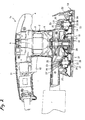
- Fig. 1 is a vertical section view of a finishing sander according to a first embodiment of the invention.
- Fig. 2 is a vertical section view of a finishing sander according to a second embodiment of the invention.
- Exemplified embodiments of the invention will be described below in detail with reference to the accompanying drawings.
- Fig. 1 shows a finishing sander 1 according to a first embodiment of the invention. The finishing sander 1 includes a
main body 2 and abase 13 provided below the main body. Themain body 2 is formed by half-dividedhousings 3 and 4 adapted to be divided vertically into two pieces. Amotor 5 is housed in themain body 2 such that anoutput shaft 6 thereof is directed downward. Theoutput shaft 6 is axially supported by ball bearings 7 that projects to the lower side of themain body 2. Acooling fan 8 is orthogonally secured to theoutput shaft 6 above the ball bearings 7. Adust collecting fan 9 is orthogonally secured to theoutput shaft 6 below the ball bearings 7. Thedust collecting fan 9 is operable to suck dust from the lower side of themain body 2 and to feed the dust to adust collecting nozzle 10 provided in a side portion of themain body 2. Thereference numeral 11 denotes a handle extended at the upper side of themain body 2, and thereference numeral 12 denotes a switch lever. - On the other hand, at the center of the
base 13, abearing box 15 forhousing ball bearings 14 is formed, and by inserting theoutput shaft 6 of themotor 5 into aneccentric hole 17 of aneccentric sleeve 16 axially supported by theball bearings 14 theoutput shaft 6 at an eccentric position via aneccentric sleeve 16 is axially supported. Thereference numerals eccentric sleeve 16, and thereference numeral 20 denotes a balancer projected from an eccentric side of theeccentric sleeve 15. - The
reference numeral 21 is a pad provided on the lower surface of thebase 13, and on its front and rear sides,clampers 22 are provided, respectively, and on the bottom surface of thepad 21, a sanding paper that is not shown can be stretched thereon. - The
reference numerals 23 denote feet laid between themain body 2 and thebase 13 and includefoot bodies 24 that have columnar shapes and are made of aluminum and rubber O-rings 26, respectively. Herein, in a state that the O-rings 26 are housed in thereceptacles 27 recessed in themain body 2 and thebase 13, respectively, so as to face each other, the O-rings are externally fitted tosmall diameter portions 25 projected from the centers of both ends of thefoot bodies 24, whereby the O-rings 26 are pressurized to elastically support thefoot bodies 24 in the axial direction thereof. Thesmall diameter portions 25 have length that does not exceed the outermost ends of the O-rings 26 in the axial direction thereof, respectively. - In this embodiment,
sponge sleeves 28 serving as elastic members are fitted onto the outer peripheries of thefoot bodies 24, respectively. Thesponge sleeve 28 is a cylindrical member slightly longer in the axial direction than the vertical interval between the upper andlower receptacles 27. In a state that thesponge sleeve 28 is fitted onto the outer periphery of thefoot body 24, the upper and lower ends come into pressure contact with the opening edges of thereceptacles 27, respectively, and deform according to the opening edge shapes, whereby closing a gap between thereceptacles 27. - In the finishing sander 1 constructed as described above, when the
switch lever 12 is pushed down to drive themotor 5, theoutput shaft 6 rotates, however, theball bearings 14 on the base 13 side axially support theoutput shaft 6 at an eccentric position via theeccentric sleeve 16, so that according to rotation of theoutput shaft 6, thebase 13 makes orbital motion (eccentric motion) around the center of axis of theoutput shaft 6. Due to this orbital motion of thebase 13, it becomes possible to sand an object material with a sanding paper stretched on the bottom surface of thebase 13. - According to the orbital motion, the
foot 23 makes so-called precession in that the lower end held by thereceptacle 27 on the base 13 side makes a circular motion following thebase 13 around a pivot set on the upper end held by thereceptacle 27 on themain body 2 side, and acts to restrict rotation of the base 13 itself and prevent vertical vibration of thebase 13. - Since the
sponge sleeve 28 is fitted onto the outer periphery of thefoot 23 so as to close a gap between thereceptacles 27, there is no possibility that dust caused by sanding enters the inside of thereceptacles 27 from the portions between thefoot body 24 and thereceptacles 27. Particularly, since thesponge sleeve 28 is elastic, even when thefoot 23 makes precession, the contact portion with thereceptacle 27 deforms following thereceptacle 27 and a closely-fitted state is maintained. In addition, even when thesponge sleeve 28 is fitted onto the outer periphery of eachfoot 23, its resistance against the base'13 making orbital motion is very small, so that it does not influence the sanding performance of the finishing sander 1 itself. - Herein, since the
foot body 24 is comprised of aluminum, it is high in rigidity and can effectively prevent vertical flopping of thebase 13, and also brings about a heat radiation effect. In addition, since both ends of thefoot body 24 are elastically supported by the O-rings 26, both ends of thefoot body 24 become free ends and smoothly make precession. Furthermore, since only a compression force acts on the O-ring 26 itself, and no shearing force or bending force is applied thereto, wearing is reduced. That is, the vibration isolating effect for the base 13 can be improved by effectively opposing this to axial vibration, and this contributes to the realization of smooth orbital motion of thebase 13. - Thus, according to the finishing sander 1 of the first embodiment, by fitting a
sponge sleeve 28 onto the outer periphery of thefoot body 24 so as to cover the exposed portion of thefoot body 24 and by bringing the upper and lower ends thereof into pressure contact with opening edges of thereceptacles 27 so as to close a gap between thereceptacles 27, high dust proofness is attained in eachfoot 23. Therefore, thefoot bodies 24, the O-rings 26, and thereceptacles 27 are prevented from being worn by dust. In addition, the above effect can be attained with the simple construction in which thesponge sleeve 28 is fitted onto the outer periphery of eachfoot 23, and special shape change for securing dust proofness or members for attaching thesponge sleeve 28 become unnecessary on themain body 2 and the base 13 including the receptacles. Therefore, a cost increase is minimized, and the shapes of themain body 2 and the base 13 are not limited. - Next, a second embodiment of the invention will be described with reference to Fig. 2. Components similar to those in the first embodiment will be designated by the same reference numerals and repetitive explanations for those will be omitted.
- In the finishing sander 1 a shown in Fig. 2, a
sponge sleeve 29 is not fitted onto the outer periphery of eachfoot 23, but is interposed between themain body 2 and the base 13 so as to surround the entire region in which thefeet 23 are provided. That is, thesponge sleeve 29 is a large cylindrical member formed along the outer contour of the lower surface of themain body 2. Thesponge sleeve 29 is slightly longer in the axial direction than the vertical interval between themain body 2 and thebase 13, and the upper end is brought into pressure contact with the lower surface of themain body 2, and the lower end is brought into pressure contact with and closely fitted to the upper surface of the base 13 on the inner side than theclamper 22, whereby closing the entire region including thefeet 23. - Therefore, in this finishing sander 1 a, since the entire region including the
feet 23 between themain body 2 and thebase 13 is covered by thesponge sleeve 29, there is no possibility that dust caused by sanding enters the insides of thereceptacles 27 from the portions between thefoot bodies 24 and thereceptacles 27. Also in this embodiment, since thesponge sleeve 29 is elastic, even when thebase 13 makes orbital motion, the portion of thesponge sleeve 29 in contact with thebase 13 deforms following this, so that the closely-fitted state is maintained. - According to the finishing sander 1 a of the second embodiment, by interposing a
sponge sleeve 29 between themain body 2 and the base 13 so as to cover the entire region including thefeet 23, the entire region including thefeet 23 is closed by bringing its upper end into pressure contact with themain body 2 and its lower end into pressure contact with thebase 13, respectively. Thus, high dust proofness is attained in eachfoot 23, and thefoot bodies 24, the O-rings 26, and thereceptacles 27 are prevented from being worn by dust. In addition, this effect can be attained with a simple construction in which asingle sponge sleeve 29 is interposed between themain body 2 and thebase 13, and special shape change for dust-proofing or attaching members for thesponge sleeve 29 become unnecessary on themain body 2 and thebase 13. Therefore, a cost increase is minimized, and the shapes of themain body 2 and the base 13 are not limited. - As a common variation of the first and second embodiments, the elastic member is not limited to a sponge, and other materials such as a synthetic resin and felt can also be used. Depending on the material, it is also possible that the thickness of the central portion is made thinner than the upper and lower ends to secure the followability to the orbital motion, or sleeves which have different diameters from one another and made from different materials from one another are coaxially overlapped with each other to form a multiple cylinder to increase the dust proofness.
- Furthermore, the
sponge sleeves 28 and thesponge sleeve 29 can be adopted at the same time, so that higher dust proofness can be obtained. - In addition, the axially supporting structure of the foot body on the receptacles is not limited to the above-described embodiments, but can be changed in design as appropriate as long as the foot body can be elastically supported in the axial direction thereof, such that the foot body is held by an angular ring with a quadrilateral sectional shape or a plurality of balls instead of the O-ring, the small diameter portions are omitted and the entire ends are held by flat rubber instead, or rubbery ball or plates are interposed between the end portions of the foot body and the receptacle bottom surface. Instead of using the same axial supporting structure at the upper side and the lower side of the foot body, mutually different structures may be used between the upper and lower sides such that the lower end with a larger motion amount is received by an O-ring and the upper end is supported by the ball or plate.
- Furthermore, the foot body may be made of a metal other than aluminum, however, the use of aluminum is preferable since it realizes a light weight, predetermined rigidity and heat radiation effect.
- Although only some exemplary embodiments of the invention have been described in detail above, those skilled in the art will readily appreciated that many modifications are possible in the exemplary embodiments without materially departing from the novel teachings and advantages of the invention. Accordingly, all such modifications are intended to be included within the scope of the invention.
- The disclosure of
Japanese Patent Application No. 2006-236079 filed August 31, 2006 - It is explicitly stated that all features disclosed in the description and/or the claims are intended to be disclosed separately and independently from each other for the purpose of original disclosure as well as for the purpose of restricting the claimed invention independent of the composition of the features in the embodiments and/or the claims. It is explicitly stated that all value ranges or indications of groups of entities disclose every possible intermediate value or intermediate entity for the purpose of original disclosure as well as for the purpose of restricting the claimed invention, in particular as limits of value ranges.
Claims (8)
- A sander, comprising:a main body;a motor, disposed in the main body and having a rotary shaft;a base, disposed below the main body, the base being coupled to the rotary shaft and adapted to make eccentric motions in accordance with rotations of the rotary shaft;a first receptacle disposed in the main body;a second receptacle disposed in the base;a foot, disposed between the first receptacle and the second receptacle, and comprising:a foot body, comprised of metal; andelastic members, provided on both ends of the foot body and respectively fitted into the first receptacle and the second receptacle, so that the foot body is pivotably supported between the first receptacle and the second receptacle; andan elastic sleeve, fitted onto a part of an outer periphery of the foot body while being compressed by the first receptacle and the second receptacle.
- The sander as set forth in claim 1, wherein:the elastic sleeve has a length longer than an interval between a lower edge of the first receptacle and an upper edge of the second receptacle; andan upper edge of the elastic sleeve is in press contact with the lower edge of the first receptacle, and a lower edge of the elastic sleeve is in press contact with the upper edge of the second receptacle.
- The sander as set forth in claim 1, wherein:the elastic sleeve is comprised of sponge.
- The sander as set forth in claim 1, wherein:the foot body is comprised of aluminum.
- A sander, comprising:a main body;a motor, disposed in the main body and having a rotary shaft;a base, disposed below the main body, the base being coupled to the rotary shaft and adapted to make eccentric motions in accordance with rotations of the rotary shaft;a first receptacle disposed in the main body;a second receptacle disposed in the base;a foot, disposed between the first receptacle and the second receptacle, and comprising:a foot body, comprised of metal; andelastic members, provided on both ends of the foot body and respectively fitted into the first receptacle and the second receptacle, so that the foot body is pivotably supported between the first receptacle and the second receptacle; andan elastic sleeve, surrounding a region in which the foot is provided, while being compressed by a lower surface of the main body and an upper surface of the base.
- The sander as set forth in claim 5, wherein:the elastic sleeve has a length longer than an interval between the lower surface of the main body and the upper surface of the base; andan upper edge of the elastic sleeve is in press contact with the lower surface of the main body, and a lower edge of the elastic sleeve is in press contact with the upper surface of the base.
- The sander as set forth in claim 5, wherein:the elastic sleeve is comprised of sponge.
- The sander as set forth in claim 5, wherein:the foot body is comprised of aluminum.
Applications Claiming Priority (1)
| Application Number | Priority Date | Filing Date | Title |
|---|---|---|---|
| JP2006236079A JP4819623B2 (en) | 2006-08-31 | 2006-08-31 | Sanda |
Publications (2)
| Publication Number | Publication Date |
|---|---|
| EP1894674A1 true EP1894674A1 (en) | 2008-03-05 |
| EP1894674B1 EP1894674B1 (en) | 2009-03-25 |
Family
ID=38779681
Family Applications (1)
| Application Number | Title | Priority Date | Filing Date |
|---|---|---|---|
| EP07016863A Not-in-force EP1894674B1 (en) | 2006-08-31 | 2007-08-28 | Sander |
Country Status (6)
| Country | Link |
|---|---|
| US (1) | US7819725B2 (en) |
| EP (1) | EP1894674B1 (en) |
| JP (1) | JP4819623B2 (en) |
| CN (1) | CN101134295A (en) |
| DE (1) | DE602007000759D1 (en) |
| RU (1) | RU2387530C2 (en) |
Cited By (1)
| Publication number | Priority date | Publication date | Assignee | Title |
|---|---|---|---|---|
| US12005542B2 (en) | 2019-05-07 | 2024-06-11 | Guido Valentini | Hand-held power tool for sending or polishing a workpiece |
Families Citing this family (11)
| Publication number | Priority date | Publication date | Assignee | Title |
|---|---|---|---|---|
| CN101797708A (en) * | 2010-03-25 | 2010-08-11 | 陈远康 | Dustless sander |
| JP2013202734A (en) * | 2012-03-28 | 2013-10-07 | Hitachi Koki Co Ltd | Power tool |
| JP2013220493A (en) * | 2012-04-13 | 2013-10-28 | Makita Corp | Sander |
| US9393658B2 (en) * | 2012-06-14 | 2016-07-19 | Black & Decker Inc. | Portable power tool |
| CN103567842B (en) * | 2012-08-07 | 2017-02-08 | 苏州宝时得电动工具有限公司 | Grinding power tool |
| US9505119B2 (en) * | 2015-02-19 | 2016-11-29 | X'pole Precision Tools Inc. | Electric handheld sanding tool providing improved cooling efficiency |
| EP3132892B1 (en) * | 2015-08-20 | 2020-11-18 | Techtronic Power Tools Technology Limited | Multi-sander kit |
| DE102016106782A1 (en) * | 2016-04-13 | 2017-10-19 | Festool Gmbh | Hand machine tool with a cover device |
| CN107617958B (en) * | 2016-07-15 | 2023-12-08 | 苏州宝时得电动工具有限公司 | Sander |
| DE102019103088A1 (en) * | 2019-02-07 | 2020-08-13 | Festool Gmbh | Machine tool with a balancing device |
| CN113523980B (en) * | 2020-04-15 | 2023-04-07 | 南京泉峰科技有限公司 | Grinding machine |
Citations (2)
| Publication number | Priority date | Publication date | Assignee | Title |
|---|---|---|---|---|
| GB814793A (en) * | 1957-04-24 | 1959-06-10 | Sundstrand Machine Tool Co | Rubbing machine |
| US20010003087A1 (en) * | 1999-12-07 | 2001-06-07 | Makita Corporation | Sanding apparatus with an improved vibration insulating mechanism |
Family Cites Families (15)
| Publication number | Priority date | Publication date | Assignee | Title |
|---|---|---|---|---|
| US3336702A (en) * | 1964-02-28 | 1967-08-22 | Black & Decker Mfg Co | Oscillating platen for abrading tool |
| US3418761A (en) * | 1966-03-28 | 1968-12-31 | Black & Decker Mfg Co | Dual-action power-operated abrading tool |
| US3849943A (en) * | 1973-02-26 | 1974-11-26 | Rockwell International Corp | Power operated sanding machine |
| JPS513988A (en) | 1974-07-02 | 1976-01-13 | Nitto Seimo Kk | Teichimono gyoruiiriguchino heisokuyoami |
| JPS58164651A (en) * | 1982-03-24 | 1983-09-29 | Mitsubishi Chem Ind Ltd | Reactive dyes for cellulose fibers |
| NL8303577A (en) * | 1983-10-17 | 1985-05-17 | Skil Nederland Nv | FLAT SANDER. |
| JPS61192465A (en) * | 1985-02-21 | 1986-08-27 | Oomi Kogyo Kk | Tool for hand grinder |
| DE3510333A1 (en) * | 1985-03-22 | 1986-09-25 | Robert Bosch Gmbh, 7000 Stuttgart | Grinder which has a planar grinding surface |
| US4686797A (en) | 1986-10-15 | 1987-08-18 | National Air Sander, Inc. | Straight-line rubbing machine with thrust transmitting members |
| US4821357A (en) * | 1988-02-23 | 1989-04-18 | Edgar Millette | Scraper adaptor for rotary buffer |
| JP2558508B2 (en) * | 1988-07-30 | 1996-11-27 | 住友金属工業株式会社 | Strip fluid support device |
| JP2664862B2 (en) * | 1993-11-19 | 1997-10-22 | エス・ピー・エアー株式会社 | Sander for water polishing |
| GB9415011D0 (en) | 1994-07-26 | 1994-09-14 | Black & Decker Inc | Improved oscillating hand tool |
| IT1298934B1 (en) * | 1997-02-27 | 2000-02-07 | Bosch Gmbh Robert | MOTOR-OPERATED PORTABLE GROUP |
| ITMI20030054U1 (en) * | 2003-02-13 | 2004-08-14 | Valentini Guido | CONNECTION FOOT FOR ORBITAL MOVING MACHINES FOR THE WORKING OF SURFACES, IN PARTICULAR FOR ORBITAL SANDERS |
-
2006
- 2006-08-31 JP JP2006236079A patent/JP4819623B2/en not_active Expired - Fee Related
-
2007
- 2007-07-18 CN CNA200710130350XA patent/CN101134295A/en active Pending
- 2007-08-28 DE DE602007000759T patent/DE602007000759D1/en active Active
- 2007-08-28 EP EP07016863A patent/EP1894674B1/en not_active Not-in-force
- 2007-08-29 US US11/896,052 patent/US7819725B2/en not_active Expired - Fee Related
- 2007-08-30 RU RU2007132746/02A patent/RU2387530C2/en not_active IP Right Cessation
Patent Citations (2)
| Publication number | Priority date | Publication date | Assignee | Title |
|---|---|---|---|---|
| GB814793A (en) * | 1957-04-24 | 1959-06-10 | Sundstrand Machine Tool Co | Rubbing machine |
| US20010003087A1 (en) * | 1999-12-07 | 2001-06-07 | Makita Corporation | Sanding apparatus with an improved vibration insulating mechanism |
Cited By (1)
| Publication number | Priority date | Publication date | Assignee | Title |
|---|---|---|---|---|
| US12005542B2 (en) | 2019-05-07 | 2024-06-11 | Guido Valentini | Hand-held power tool for sending or polishing a workpiece |
Also Published As
| Publication number | Publication date |
|---|---|
| RU2387530C2 (en) | 2010-04-27 |
| US7819725B2 (en) | 2010-10-26 |
| CN101134295A (en) | 2008-03-05 |
| RU2007132746A (en) | 2009-03-10 |
| EP1894674B1 (en) | 2009-03-25 |
| JP2008055559A (en) | 2008-03-13 |
| JP4819623B2 (en) | 2011-11-24 |
| US20080057841A1 (en) | 2008-03-06 |
| DE602007000759D1 (en) | 2009-05-07 |
Similar Documents
| Publication | Publication Date | Title |
|---|---|---|
| EP1894674B1 (en) | Sander | |
| US10357868B2 (en) | Grinder, cover, and lock nut | |
| US8105132B2 (en) | Eccentric grinder | |
| US8475236B2 (en) | Sander having a damping element | |
| CN102256745B (en) | Hand held machine for grinding and like operations | |
| CN101032816A (en) | Power tool | |
| US7201643B2 (en) | Handle assembly for tool | |
| JPH0630339Y2 (en) | Reciprocating tool | |
| US2722789A (en) | Rubbing attachment for portable rotary power units | |
| KR20200130112A (en) | Hand-Held Power Tool for Sanding or Polishing a Workpiece | |
| CN1899765B (en) | Devices with at least two counterweights, eccentric tools and hand-held power tools | |
| WO2026021247A1 (en) | Power tool | |
| US6039639A (en) | Motor driven hand tool with improved elastic supporting members connecting an oscillating work tool carrier with the tool housing | |
| JPH10264028A (en) | Polishing plate for hand-held power tool with dust suction means | |
| JP2002018693A (en) | Hand-held machine tool | |
| CN211890296U (en) | Polishing device | |
| JP2006504540A (en) | Bearing device for supporting a grinding disk to vibrate on a grinding tool | |
| EP0167679B1 (en) | Polishing apparatus | |
| CN105983893A (en) | Handheld sander | |
| JP3508261B2 (en) | Vibration tool | |
| JP2005511330A (en) | Hand-held vibration grinder | |
| CN115723013A (en) | grinding tool | |
| GB578027A (en) | Improvements in or relating to rubbing, sanding, or polishing machine | |
| CN222471970U (en) | Sanding machine | |
| JP2004066420A (en) | Orbital sander |
Legal Events
| Date | Code | Title | Description |
|---|---|---|---|
| PUAI | Public reference made under article 153(3) epc to a published international application that has entered the european phase |
Free format text: ORIGINAL CODE: 0009012 |
|
| AK | Designated contracting states |
Kind code of ref document: A1 Designated state(s): AT BE BG CH CY CZ DE DK EE ES FI FR GB GR HU IE IS IT LI LT LU LV MC MT NL PL PT RO SE SI SK TR |
|
| AX | Request for extension of the european patent |
Extension state: AL BA HR MK YU |
|
| 17P | Request for examination filed |
Effective date: 20080903 |
|
| GRAP | Despatch of communication of intention to grant a patent |
Free format text: ORIGINAL CODE: EPIDOSNIGR1 |
|
| AKX | Designation fees paid |
Designated state(s): DE FR GB |
|
| GRAS | Grant fee paid |
Free format text: ORIGINAL CODE: EPIDOSNIGR3 |
|
| GRAA | (expected) grant |
Free format text: ORIGINAL CODE: 0009210 |
|
| AK | Designated contracting states |
Kind code of ref document: B1 Designated state(s): DE FR GB |
|
| REG | Reference to a national code |
Ref country code: GB Ref legal event code: FG4D |
|
| REF | Corresponds to: |
Ref document number: 602007000759 Country of ref document: DE Date of ref document: 20090507 Kind code of ref document: P |
|
| PLBE | No opposition filed within time limit |
Free format text: ORIGINAL CODE: 0009261 |
|
| STAA | Information on the status of an ep patent application or granted ep patent |
Free format text: STATUS: NO OPPOSITION FILED WITHIN TIME LIMIT |
|
| 26N | No opposition filed |
Effective date: 20091229 |
|
| PGFP | Annual fee paid to national office [announced via postgrant information from national office to epo] |
Ref country code: DE Payment date: 20130821 Year of fee payment: 7 |
|
| PGFP | Annual fee paid to national office [announced via postgrant information from national office to epo] |
Ref country code: GB Payment date: 20130828 Year of fee payment: 7 Ref country code: FR Payment date: 20130808 Year of fee payment: 7 |
|
| REG | Reference to a national code |
Ref country code: DE Ref legal event code: R119 Ref document number: 602007000759 Country of ref document: DE |
|
| GBPC | Gb: european patent ceased through non-payment of renewal fee |
Effective date: 20140828 |
|
| REG | Reference to a national code |
Ref country code: DE Ref legal event code: R119 Ref document number: 602007000759 Country of ref document: DE Effective date: 20150303 |
|
| REG | Reference to a national code |
Ref country code: FR Ref legal event code: ST Effective date: 20150430 |
|
| PG25 | Lapsed in a contracting state [announced via postgrant information from national office to epo] |
Ref country code: GB Free format text: LAPSE BECAUSE OF NON-PAYMENT OF DUE FEES Effective date: 20140828 Ref country code: DE Free format text: LAPSE BECAUSE OF NON-PAYMENT OF DUE FEES Effective date: 20150303 |
|
| PG25 | Lapsed in a contracting state [announced via postgrant information from national office to epo] |
Ref country code: FR Free format text: LAPSE BECAUSE OF NON-PAYMENT OF DUE FEES Effective date: 20140901 |