EP1894666A2 - Laser hardening device - Google Patents
Laser hardening device Download PDFInfo
- Publication number
- EP1894666A2 EP1894666A2 EP07405227A EP07405227A EP1894666A2 EP 1894666 A2 EP1894666 A2 EP 1894666A2 EP 07405227 A EP07405227 A EP 07405227A EP 07405227 A EP07405227 A EP 07405227A EP 1894666 A2 EP1894666 A2 EP 1894666A2
- Authority
- EP
- European Patent Office
- Prior art keywords
- torch
- axis
- hardening
- main spindle
- bed
- Prior art date
- Legal status (The legal status is an assumption and is not a legal conclusion. Google has not performed a legal analysis and makes no representation as to the accuracy of the status listed.)
- Withdrawn
Links
Images




Classifications
-
- B—PERFORMING OPERATIONS; TRANSPORTING
- B23—MACHINE TOOLS; METAL-WORKING NOT OTHERWISE PROVIDED FOR
- B23K—SOLDERING OR UNSOLDERING; WELDING; CLADDING OR PLATING BY SOLDERING OR WELDING; CUTTING BY APPLYING HEAT LOCALLY, e.g. FLAME CUTTING; WORKING BY LASER BEAM
- B23K26/00—Working by laser beam, e.g. welding, cutting or boring
- B23K26/14—Working by laser beam, e.g. welding, cutting or boring using a fluid stream, e.g. a jet of gas, in conjunction with the laser beam; Nozzles therefor
- B23K26/1462—Nozzles; Features related to nozzles
- B23K26/1482—Detachable nozzles, e.g. exchangeable or provided with breakaway lines
-
- B—PERFORMING OPERATIONS; TRANSPORTING
- B23—MACHINE TOOLS; METAL-WORKING NOT OTHERWISE PROVIDED FOR
- B23K—SOLDERING OR UNSOLDERING; WELDING; CLADDING OR PLATING BY SOLDERING OR WELDING; CUTTING BY APPLYING HEAT LOCALLY, e.g. FLAME CUTTING; WORKING BY LASER BEAM
- B23K26/00—Working by laser beam, e.g. welding, cutting or boring
- B23K26/08—Devices involving relative movement between laser beam and workpiece
- B23K26/0823—Devices involving rotation of the workpiece
-
- C—CHEMISTRY; METALLURGY
- C21—METALLURGY OF IRON
- C21D—MODIFYING THE PHYSICAL STRUCTURE OF FERROUS METALS; GENERAL DEVICES FOR HEAT TREATMENT OF FERROUS OR NON-FERROUS METALS OR ALLOYS; MAKING METAL MALLEABLE, e.g. BY DECARBURISATION OR TEMPERING
- C21D1/00—General methods or devices for heat treatment, e.g. annealing, hardening, quenching or tempering
- C21D1/06—Surface hardening
- C21D1/09—Surface hardening by direct application of electrical or wave energy; by particle radiation
-
- Y—GENERAL TAGGING OF NEW TECHNOLOGICAL DEVELOPMENTS; GENERAL TAGGING OF CROSS-SECTIONAL TECHNOLOGIES SPANNING OVER SEVERAL SECTIONS OF THE IPC; TECHNICAL SUBJECTS COVERED BY FORMER USPC CROSS-REFERENCE ART COLLECTIONS [XRACs] AND DIGESTS
- Y10—TECHNICAL SUBJECTS COVERED BY FORMER USPC
- Y10T—TECHNICAL SUBJECTS COVERED BY FORMER US CLASSIFICATION
- Y10T483/00—Tool changing
- Y10T483/17—Tool changing including machine tool or component
Definitions
- the present invention relates to a laser hardening device having a laser torch changer.
- Japanese Patent Application Laid-Open Publication No. 2005-334951 (patent document 1) filed by the present applicant discloses an art of attaching a laser hardening tool to a main spindle of a machine tool so as to perform hardening within the machine tool.
- Patent document 2 discloses a semiconductor laser device.
- Semiconductor laser is capable of irradiating a beam with an extremely small spot.
- the irradiated portion is heated to hardening temperature, but the temperature of the whole component is not raised, so a hardening layer is formed to the irradiated portion via a self-cooling effect.
- the object of the present invention is to focus on such semiconductor laser, and to provide a laser hardening device with an automatic changer for changing laser torches to correspond to the shapes of works.
- the laser hardening device of the present invention comprises a bed; a table disposed on a bed and rotating around axis C; a column disposed on the bed and moving along axis Y orthogonal to axis C; a head having a semiconductor laser oscillator supported by the column and moving along axis Z orthogonal to axis Y; a main spindle supported by the head and rotating around axis B; a hardening torch attached removably to the main spindle; and a torch automatic changer disposed on the bed.
- the torch automatic changer comprises a rotating magazine, a torch holder disposed on an outer circumference of the magazine, and a mechanism for moving the torch holder allocated to a torch changing position up and down toward the main spindle of the head.
- the laser hardening device irradiates the laser beam output from the semiconductor laser oscillator on the surface of a work to realize hardening via the self-cooling effect of the work. Since the present device includes within the device a torch automatic changer for attaching torches to a main spindle of the hardening head, it becomes possible to select a suitable torch for hardening and to automate the hardening process.
- FIG. 1 is a perspective view showing the outline of a laser hardening device according to the present invention.
- the laser hardening device denoted as a whole by reference number 1 has a table 20 disposed on a bed 10, and a chuck 22 disposed on the table 20.
- the table 20 is rotated around axis C.
- a column 30 driven in the direction of axis Y is disposed on the bed 10, and on the front side of the column 30 is disposed a hardening head 40 capable of being moved in sliding motion in the direction of axis Z.
- the hardening head 40 has a main spindle 50, and on the main spindle 50 is attached a hardening torch T in a changeable manner.
- the main spindle 50 is rotated around axis B.
- the laser hardening device 1 does not have a sliding axis in the direction of axis X that is orthogonal to axis Y within the horizontal plane.
- Axis X is composed of a composite axis of axis B of the main spindle 50 and the table 20.
- the laser hardening device 1 is equipped with an electric panel 60 and an NC device 70.
- the hardening head 40 stores a semiconductor laser unit, and the laser beam irradiated from the semiconductor laser unit is conducted via the torch T, converged via an optical system including a lens, and forms a spot on the surface of a work gripped by a chuck 22 to thereby perform hardening.
- a torch automatic changer 100 is disposed adjacent to the table 20 on the bed 10.
- the torch automatic changer 100 has a rotating magazine, and a plurality of torches T to be changed are stored at the outer circumference portion of the magazine.
- FIG. 2 shows the outline of the main spindle 50.
- the main spindle 50 is driven to rotate around axis B via a worm mechanism 51.
- a hardening torch T is attached in a replaceable manner to the main spindle 50.
- the hardening torch T has a reflecting mirror M 1 for irradiating a laser beamLB through a nozzle N to the direction orthogonal to axis B.
- Various types of hardening torch structures are prepared to correspond to the various shapes of works, such as for irradiating the laser beam LB to the direction of axis B or for irradiating the laser beam LB at an angle of 45 degrees with respect to axis B.
- FIGS. 3 and 4 are explanatory views showing the structure of the torch automatic changer 100.
- a base 110 is fixed to the side toward the bed 10, and on the base 110 is disposed a magazine 120 in a rotatable manner.
- a plurality of torch holders 130 are disposed on the outer circumference portion of the magazine 120 for storing torches T.
- a rotating cover 134 is disposed on an upper portion of the torch holder 130 for protecting the opening at the upper portion of the stored torch T.
- a rear end portion of a cylinder 150 is supported on the side of the bed 10, and the leading end of a rod 152 is connected to a link arm 154.
- a joint portion 156 at the leading end of the link arm 154 moves the rod 160 up and down.
- the rod 160 moves the torch holder 130 allocated to the torch changing position up and down.
- the torch holder 130 has a mechanism for rotating and opening the cover 134 against a spring force in synchronism with the elevating movement.
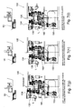
- FIGS. 5 through 8 illustrate the automatic changing operation of torches.
- the main spindle 50 of a processing head to which the used torch T 1 is attached moves to an ATC position above a torch automatic changer 100.
- the cylinder 150 is operated to elevate the rod 160, and a vacant torch holder 130 for receiving the used torch T 1 allocated in advance to the ATC position is elevated. By this elevating movement, a clamp base collides against a restriction bolt 132.
- the cover 134 rotates to open the torch holder 130.
- the main spindle 50 moves downward in the direction of axis Z to return the torch T 1 of the main spindle to the torch holder 130, and in FIG. 6(f), the main spindle is elevated and retreated.
- the magazine 120 of the torch automatic exchanger 100 is rotated, and the torch holder 130 storing the torch T 2 to be presently used is allocated to the ATC position.
- the cylinder 150 is operated to elevate the torch holder 130 via the rod 160, and the cover 134 is opened.
- the main spindle 50 is lowered to receive the torch T 2 .
- FIG. 9 is a flowchart showing the automatic torch changing process described above.
Landscapes
- Engineering & Computer Science (AREA)
- Physics & Mathematics (AREA)
- Optics & Photonics (AREA)
- Chemical & Material Sciences (AREA)
- Mechanical Engineering (AREA)
- Plasma & Fusion (AREA)
- Thermal Sciences (AREA)
- Crystallography & Structural Chemistry (AREA)
- Materials Engineering (AREA)
- Metallurgy (AREA)
- Organic Chemistry (AREA)
- Automatic Tool Replacement In Machine Tools (AREA)
- Heat Treatment Of Articles (AREA)
- Laser Beam Processing (AREA)
Abstract
Description
- The present invention relates to a laser hardening device having a laser torch changer.
-
Japanese Patent Application Laid-Open Publication No. 2005-334951 -
Japanese Patent Application Laid-Open Publication No. 2004-130335 - Semiconductor laser is capable of irradiating a beam with an extremely small spot. When such beam is irradiated on a surface of ametal component, the irradiated portion is heated to hardening temperature, but the temperature of the whole component is not raised, so a hardening layer is formed to the irradiated portion via a self-cooling effect.
- The object of the present invention is to focus on such semiconductor laser, and to provide a laser hardening device with an automatic changer for changing laser torches to correspond to the shapes of works.
- In order to achieve this object, the laser hardening device of the present invention comprises a bed; a table disposed on a bed and rotating around axis C; a column disposed on the bed and moving along axis Y orthogonal to axis C; a head having a semiconductor laser oscillator supported by the column and moving along axis Z orthogonal to axis Y; a main spindle supported by the head and rotating around axis B; a hardening torch attached removably to the main spindle; and a torch automatic changer disposed on the bed.
- Further, the torch automatic changer comprises a rotating magazine, a torch holder disposed on an outer circumference of the magazine, and a mechanism for moving the torch holder allocated to a torch changing position up and down toward the main spindle of the head.
- The laser hardening device according to the present invention irradiates the laser beam output from the semiconductor laser oscillator on the surface of a work to realize hardening via the self-cooling effect of the work. Since the present device includes within the device a torch automatic changer for attaching torches to a main spindle of the hardening head, it becomes possible to select a suitable torch for hardening and to automate the hardening process.
-
- FIG. 1 is a perspective view showing the outline of the laser hardening device according to the present invention;
- FIG. 2 is an explanatory view showing the outline of the main spindle;
- FIG. 3 is an explanatory view showing the structure of the torch automatic changer;
- FIG. 4 is an explanatory view showing the structure of the torch automatic changer;
- FIG. 5 is an explanatory view showing the automatic changing operation of torches;
- FIG. 6 is an explanatory view showing the automatic changing operation of torches;
- FIG. 7 is an explanatory view showing the automatic changing operation of torches;
- FIG. 8 is an explanatory view showing the automatic changing operation of torches; and
- FIG. 9 is a flowchart showing the automatic torch changing process.
- FIG. 1 is a perspective view showing the outline of a laser hardening device according to the present invention.
- The laser hardening device denoted as a whole by reference number 1 has a table 20 disposed on a
bed 10, and achuck 22 disposed on the table 20. The table 20 is rotated around axis C. Acolumn 30 driven in the direction of axis Y is disposed on thebed 10, and on the front side of thecolumn 30 is disposed a hardeninghead 40 capable of being moved in sliding motion in the direction of axis Z. - The hardening
head 40 has amain spindle 50, and on themain spindle 50 is attached a hardening torch T in a changeable manner. Themain spindle 50 is rotated around axis B. The laser hardening device 1 does not have a sliding axis in the direction of axis X that is orthogonal to axis Y within the horizontal plane. Axis X is composed of a composite axis of axis B of themain spindle 50 and the table 20. The laser hardening device 1 is equipped with anelectric panel 60 and anNC device 70. - The hardening
head 40 stores a semiconductor laser unit, and the laser beam irradiated from the semiconductor laser unit is conducted via the torch T, converged via an optical system including a lens, and forms a spot on the surface of a work gripped by achuck 22 to thereby perform hardening. - A torch
automatic changer 100 is disposed adjacent to the table 20 on thebed 10. The torchautomatic changer 100 has a rotating magazine, and a plurality of torches T to be changed are stored at the outer circumference portion of the magazine. - FIG. 2 shows the outline of the
main spindle 50. Themain spindle 50 is driven to rotate around axis B via aworm mechanism 51. A hardening torch T is attached in a replaceable manner to themain spindle 50. The hardening torch T has a reflecting mirror M1 for irradiating a laser beamLB through a nozzle N to the direction orthogonal to axis B. Various types of hardening torch structures are prepared to correspond to the various shapes of works, such as for irradiating the laser beam LB to the direction of axis B or for irradiating the laser beam LB at an angle of 45 degrees with respect to axis B. - FIGS. 3 and 4 are explanatory views showing the structure of the torch
automatic changer 100. - A
base 110 is fixed to the side toward thebed 10, and on thebase 110 is disposed amagazine 120 in a rotatable manner. - A plurality of
torch holders 130 are disposed on the outer circumference portion of themagazine 120 for storing torches T. A rotatingcover 134 is disposed on an upper portion of thetorch holder 130 for protecting the opening at the upper portion of the stored torch T. - A rear end portion of a
cylinder 150 is supported on the side of thebed 10, and the leading end of arod 152 is connected to alink arm 154. Ajoint portion 156 at the leading end of thelink arm 154 moves therod 160 up and down. Therod 160 moves thetorch holder 130 allocated to the torch changing position up and down. Thetorch holder 130 has a mechanism for rotating and opening thecover 134 against a spring force in synchronism with the elevating movement. - FIGS. 5 through 8 illustrate the automatic changing operation of torches.
- When an order to change torches is received, as shown in FIG. 5(a), the
main spindle 50 of a processing head to which the used torch T1 is attached moves to an ATC position above a torchautomatic changer 100. In FIG. 5(b), thecylinder 150 is operated to elevate therod 160, and avacant torch holder 130 for receiving the used torch T1 allocated in advance to the ATC position is elevated. By this elevating movement, a clamp base collides against arestriction bolt 132. - When the
torch holder 130 is elevated further, a rotation-preventingkey 136 is released, as shown in FIG. 5(c). - In FIG. 6(d), the
cover 134 rotates to open thetorch holder 130. In FIG. 6(e), themain spindle 50 moves downward in the direction of axis Z to return the torch T1 of the main spindle to thetorch holder 130, and in FIG. 6(f), the main spindle is elevated and retreated. - In FIG. 7(g), the
cylinder 150 starts its return stroke, and thetorch holder 130 starts to descend via therod 160. By this movement, thecover 134 is closed, and in FIG. 7(h), thecylinder 150 reaches its stroke end, and thetorch holder 130 is returned to its fixed position. - In FIG. 7(i), the
magazine 120 of the torchautomatic exchanger 100 is rotated, and thetorch holder 130 storing the torch T2 to be presently used is allocated to the ATC position. - In FIG. 8(j), the
cylinder 150 is operated to elevate thetorch holder 130 via therod 160, and thecover 134 is opened. - In FIG. 8(k), the
main spindle 50 is lowered to receive the torch T2. - In FIG. 8(l), the
main spindle 50 having the torch T2 to be presently used attached thereto and the processing head are elevated, thetorch holder 130 is lowered to its fixed position, and the automatic torch changing cycle is completed. - FIG. 9 is a flowchart showing the automatic torch changing process described above.
Claims (2)
- A laser hardening device comprising:a bed;a table disposed on a bed and rotating around axis C;a column disposed on the bed and moving along axis Y orthogonal to axis C;a head having a semiconductor laser oscillator supported by the column and moving along axis Z orthogonal to axis Y;a main spindle supported by the head and rotating around axis B;a laser hardening torch attached removably to the main spindle; anda torch automatic changer disposed on the bed.
- The laser hardening device according to claim 1, wherein the torch automatic changer comprises a rotating magazine, a torch holder disposed on an outer circumference of the magazine, and a mechanism for moving the torch holder allocated to a torch changing position up and down toward the main spindle of the head.
Applications Claiming Priority (1)
| Application Number | Priority Date | Filing Date | Title |
|---|---|---|---|
| JP2006232342A JP5073247B2 (en) | 2006-08-29 | 2006-08-29 | Laser hardening equipment |
Publications (2)
| Publication Number | Publication Date |
|---|---|
| EP1894666A2 true EP1894666A2 (en) | 2008-03-05 |
| EP1894666A3 EP1894666A3 (en) | 2010-04-07 |
Family
ID=38866070
Family Applications (1)
| Application Number | Title | Priority Date | Filing Date |
|---|---|---|---|
| EP07405227A Withdrawn EP1894666A3 (en) | 2006-08-29 | 2007-08-02 | Laser hardening device |
Country Status (4)
| Country | Link |
|---|---|
| US (1) | US20080053975A1 (en) |
| EP (1) | EP1894666A3 (en) |
| JP (1) | JP5073247B2 (en) |
| CN (1) | CN101134268B (en) |
Cited By (2)
| Publication number | Priority date | Publication date | Assignee | Title |
|---|---|---|---|---|
| CN107177723A (en) * | 2017-06-30 | 2017-09-19 | 中国地质大学(武汉) | A kind of small sized metallic part surface laser thermal treatment platform |
| US20240261866A1 (en) * | 2021-06-04 | 2024-08-08 | Dmg Mori Co., Ltd. | Work Machine |
Families Citing this family (6)
| Publication number | Priority date | Publication date | Assignee | Title |
|---|---|---|---|---|
| US8769786B1 (en) * | 2009-03-24 | 2014-07-08 | Honda Motor Co., Ltd. | Trim and flame robot end effector with optional automatic blade change feature |
| GB2492614B (en) * | 2012-02-28 | 2014-01-29 | Barclays Bank Plc | System and method for authenticating a payment transaction |
| CN103203539B (en) * | 2013-03-25 | 2015-12-23 | 武汉团结点金激光科技有限公司 | The telescopic laser process machine of column mobile model shaven head |
| JP6033368B1 (en) * | 2015-06-15 | 2016-11-30 | Dmg森精機株式会社 | Processing machine |
| RU2708285C1 (en) * | 2017-12-29 | 2019-12-05 | Общество с ограниченной ответственностью "Новые технологии лазерного термоупрочнения" (ООО "НТЛТ") | Automated laser processing system for thermal strengthening of part surface |
| CN109266811B (en) * | 2018-12-06 | 2023-11-14 | 淮南舜立机械有限责任公司 | Laser surface treatment device for upright post oil cylinder |
Family Cites Families (13)
| Publication number | Priority date | Publication date | Assignee | Title |
|---|---|---|---|---|
| JPS61164738A (en) * | 1985-01-14 | 1986-07-25 | Toyoda Mach Works Ltd | Machine tool capable of laser beam machining |
| JPS6357039U (en) * | 1986-10-02 | 1988-04-16 | ||
| JP3583187B2 (en) * | 1995-04-19 | 2004-10-27 | ジヤトコ株式会社 | Laser hardening equipment |
| CN1161267A (en) * | 1995-09-14 | 1997-10-08 | 邵文远 | Compositions of metal-working machines |
| JP3763734B2 (en) * | 2000-10-27 | 2006-04-05 | 株式会社日立製作所 | Panel member processing method |
| CN2478727Y (en) * | 2000-11-08 | 2002-02-27 | 岳少敏 | Six-coordinate numerial control cutter grinding machine |
| JP3503939B2 (en) * | 2001-05-31 | 2004-03-08 | ヤマザキマザック株式会社 | Quenching equipment and quenching method |
| US7045738B1 (en) * | 2002-10-01 | 2006-05-16 | Southern Methodist University | Powder delivery system and method |
| JP2004130335A (en) * | 2002-10-09 | 2004-04-30 | Matsushita Electric Ind Co Ltd | Semiconductor laser device |
| JP3725129B2 (en) * | 2003-02-25 | 2005-12-07 | ファナック株式会社 | Automatic tool tip changer for robot |
| JP4431420B2 (en) * | 2004-02-24 | 2010-03-17 | ヤマザキマザック株式会社 | Machine Tools |
| US7248614B2 (en) * | 2004-02-24 | 2007-07-24 | Yamazaki Mazak Kabushiki Kaisha | Laser beam generating unit |
| JP4390627B2 (en) * | 2004-05-28 | 2009-12-24 | ヤマザキマザック株式会社 | Laser hardening tool |
-
2006
- 2006-08-29 JP JP2006232342A patent/JP5073247B2/en active Active
-
2007
- 2007-06-26 US US11/768,243 patent/US20080053975A1/en not_active Abandoned
- 2007-08-02 EP EP07405227A patent/EP1894666A3/en not_active Withdrawn
- 2007-08-08 CN CN2007101411383A patent/CN101134268B/en not_active Expired - Fee Related
Cited By (2)
| Publication number | Priority date | Publication date | Assignee | Title |
|---|---|---|---|---|
| CN107177723A (en) * | 2017-06-30 | 2017-09-19 | 中国地质大学(武汉) | A kind of small sized metallic part surface laser thermal treatment platform |
| US20240261866A1 (en) * | 2021-06-04 | 2024-08-08 | Dmg Mori Co., Ltd. | Work Machine |
Also Published As
| Publication number | Publication date |
|---|---|
| US20080053975A1 (en) | 2008-03-06 |
| JP5073247B2 (en) | 2012-11-14 |
| CN101134268B (en) | 2010-06-02 |
| EP1894666A3 (en) | 2010-04-07 |
| JP2008055441A (en) | 2008-03-13 |
| CN101134268A (en) | 2008-03-05 |
Similar Documents
| Publication | Publication Date | Title |
|---|---|---|
| US20080053975A1 (en) | Laser hardening device | |
| US7367930B2 (en) | Automatic tool changer of laser beam machine | |
| JP6033368B1 (en) | Processing machine | |
| CN107427972B (en) | Processing machinery | |
| CN107427928B (en) | Processing method of workpiece | |
| CN101590744B (en) | Hand-held laser marking machine and universal holding frame thereof thereof | |
| CN100404189C (en) | Tool exchange boxes in laser processing machines | |
| JP2019010698A (en) | Machine tool | |
| CN115702059B (en) | Processing machine | |
| JP5065799B2 (en) | Vertical machine tool | |
| KR101120835B1 (en) | Laser machining apparatus with tilting and autofocusing function | |
| CN207087142U (en) | A kind of laser accurate rotary marking machine | |
| JP4271696B2 (en) | Automatic tool changer for laser processing machines | |
| JP7527483B2 (en) | Work Machine | |
| JP4235156B2 (en) | Tool changer for machine tools | |
| JP2009160597A (en) | Laser welding equipment | |
| JP3657126B2 (en) | Laser remote welding and cutting equipment for fusion reactor blankets | |
| JP2006326768A (en) | Automatic tool exchanging device of machine tool | |
| CN210451387U (en) | Marking machine based on picosecond laser | |
| CN111819024A (en) | Device and method for machining workpieces by means of a laser beam | |
| CN215145701U (en) | Manual-automatic integrated laser welding machine | |
| CN223734114U (en) | Laser cutting device for automobile steering sub-bracket | |
| CN219234257U (en) | A turntable rotary laser welding equipment | |
| JP7608988B2 (en) | Machine Tools | |
| JPH1158161A (en) | Horizontal machining center |
Legal Events
| Date | Code | Title | Description |
|---|---|---|---|
| PUAI | Public reference made under article 153(3) epc to a published international application that has entered the european phase |
Free format text: ORIGINAL CODE: 0009012 |
|
| AK | Designated contracting states |
Kind code of ref document: A2 Designated state(s): AT BE BG CH CY CZ DE DK EE ES FI FR GB GR HU IE IS IT LI LT LU LV MC MT NL PL PT RO SE SI SK TR |
|
| AX | Request for extension of the european patent |
Extension state: AL BA HR MK YU |
|
| PUAL | Search report despatched |
Free format text: ORIGINAL CODE: 0009013 |
|
| AK | Designated contracting states |
Kind code of ref document: A3 Designated state(s): AT BE BG CH CY CZ DE DK EE ES FI FR GB GR HU IE IS IT LI LT LU LV MC MT NL PL PT RO SE SI SK TR |
|
| AX | Request for extension of the european patent |
Extension state: AL BA HR MK RS |
|
| AKY | No designation fees paid | ||
| REG | Reference to a national code |
Ref country code: DE Ref legal event code: 8566 |
|
| STAA | Information on the status of an ep patent application or granted ep patent |
Free format text: STATUS: THE APPLICATION IS DEEMED TO BE WITHDRAWN |
|
| 18D | Application deemed to be withdrawn |
Effective date: 20101008 |