EP1893494B1 - Netting knife cutter - Google Patents
Netting knife cutter Download PDFInfo
- Publication number
- EP1893494B1 EP1893494B1 EP20060760328 EP06760328A EP1893494B1 EP 1893494 B1 EP1893494 B1 EP 1893494B1 EP 20060760328 EP20060760328 EP 20060760328 EP 06760328 A EP06760328 A EP 06760328A EP 1893494 B1 EP1893494 B1 EP 1893494B1
- Authority
- EP
- European Patent Office
- Prior art keywords
- netting
- iris
- product tube
- clipper
- gather
- Prior art date
- Legal status (The legal status is an assumption and is not a legal conclusion. Google has not performed a legal analysis and makes no representation as to the accuracy of the status listed.)
- Not-in-force
Links
- 239000000463 material Substances 0.000 claims abstract description 59
- 208000019300 CLIPPERS Diseases 0.000 claims abstract description 43
- 208000021930 chronic lymphocytic inflammation with pontine perivascular enhancement responsive to steroids Diseases 0.000 claims abstract description 43
- 230000005484 gravity Effects 0.000 claims description 5
- 210000000554 iris Anatomy 0.000 abstract description 94
- 238000000034 method Methods 0.000 abstract description 20
- 241000286209 Phasianidae Species 0.000 description 17
- 235000013305 food Nutrition 0.000 description 7
- 235000013580 sausages Nutrition 0.000 description 7
- 238000011109 contamination Methods 0.000 description 6
- 230000008569 process Effects 0.000 description 6
- 230000000712 assembly Effects 0.000 description 5
- 238000000429 assembly Methods 0.000 description 5
- 238000004806 packaging method and process Methods 0.000 description 5
- 244000144977 poultry Species 0.000 description 5
- 230000000391 smoking effect Effects 0.000 description 5
- 240000002129 Malva sylvestris Species 0.000 description 4
- 235000006770 Malva sylvestris Nutrition 0.000 description 4
- 235000013351 cheese Nutrition 0.000 description 4
- 239000000835 fiber Substances 0.000 description 4
- 241000894006 Bacteria Species 0.000 description 3
- 230000008901 benefit Effects 0.000 description 3
- 238000004519 manufacturing process Methods 0.000 description 3
- 241000288147 Meleagris gallopavo Species 0.000 description 2
- 239000007844 bleaching agent Substances 0.000 description 2
- 210000000481 breast Anatomy 0.000 description 2
- 238000010411 cooking Methods 0.000 description 2
- 241000271566 Aves Species 0.000 description 1
- 229920000742 Cotton Polymers 0.000 description 1
- 230000001580 bacterial effect Effects 0.000 description 1
- 230000008859 change Effects 0.000 description 1
- 238000012864 cross contamination Methods 0.000 description 1
- 230000006378 damage Effects 0.000 description 1
- 229920002457 flexible plastic Polymers 0.000 description 1
- 238000012986 modification Methods 0.000 description 1
- 230000004048 modification Effects 0.000 description 1
- 230000008520 organization Effects 0.000 description 1
- 239000005022 packaging material Substances 0.000 description 1
- 239000004033 plastic Substances 0.000 description 1
- 229920003023 plastic Polymers 0.000 description 1
- 229920001169 thermoplastic Polymers 0.000 description 1
- 239000004416 thermosoftening plastic Substances 0.000 description 1
Images







Classifications
-
- B—PERFORMING OPERATIONS; TRANSPORTING
- B65—CONVEYING; PACKING; STORING; HANDLING THIN OR FILAMENTARY MATERIAL
- B65B—MACHINES, APPARATUS OR DEVICES FOR, OR METHODS OF, PACKAGING ARTICLES OR MATERIALS; UNPACKING
- B65B9/00—Enclosing successive articles, or quantities of material, e.g. liquids or semiliquids, in flat, folded, or tubular webs of flexible sheet material; Subdividing filled flexible tubes to form packages
- B65B9/10—Enclosing successive articles, or quantities of material, in preformed tubular webs, or in webs formed into tubes around filling nozzles, e.g. extruded tubular webs
- B65B9/15—Enclosing successive articles, or quantities of material, in preformed tubular webs, or in webs formed into tubes around filling nozzles, e.g. extruded tubular webs the preformed tubular webs being stored on filling nozzles
-
- B—PERFORMING OPERATIONS; TRANSPORTING
- B65—CONVEYING; PACKING; STORING; HANDLING THIN OR FILAMENTARY MATERIAL
- B65B—MACHINES, APPARATUS OR DEVICES FOR, OR METHODS OF, PACKAGING ARTICLES OR MATERIALS; UNPACKING
- B65B25/00—Packaging other articles presenting special problems
- B65B25/06—Packaging slices or specially-shaped pieces of meat, cheese, or other plastic or tacky products
- B65B25/064—Packaging slices or specially-shaped pieces of meat, cheese, or other plastic or tacky products of poultry
-
- Y—GENERAL TAGGING OF NEW TECHNOLOGICAL DEVELOPMENTS; GENERAL TAGGING OF CROSS-SECTIONAL TECHNOLOGIES SPANNING OVER SEVERAL SECTIONS OF THE IPC; TECHNICAL SUBJECTS COVERED BY FORMER USPC CROSS-REFERENCE ART COLLECTIONS [XRACs] AND DIGESTS
- Y10—TECHNICAL SUBJECTS COVERED BY FORMER USPC
- Y10T—TECHNICAL SUBJECTS COVERED BY FORMER US CLASSIFICATION
- Y10T83/00—Cutting
- Y10T83/869—Means to drive or to guide tool
- Y10T83/8798—With simple oscillating motion only
- Y10T83/8804—Tool driver movable relative to tool support
- Y10T83/8808—Toggle links, one link pivoted to tool support
Definitions
- This invention is generally directed to a system for enclosing materials, such as poultry, hams or other materials, in netting and applying a handle and a label to the package.
- a system for enclosing materials such as poultry, hams or other materials, in netting and applying a handle and a label to the package.
- Such an apparatus is discloses in US 2004/0068964 A1 .
- the food industry often wishes to place products in nets.
- large fowl, particularly turkeys are encased in a plastic, see-through wrapper, for sanitary reasons, and then enclosed in netting for package integrity and ease of handling.
- the netting provides a strong structure to hold the turkey and allows the consumer to see the packaged material. It is important that the netting be tight around the package, to provide a pleasing appearance to consumers. There is a marketing advantage to having tightly-netted packages.
- Nets are also applied to other food products, such as poultry, hams, sausages, or cheeses, prior to further processing, such as smoking.
- a handle is also applied to the package. Sausages and hams are enclosed in netting prior to cooking or smoking. The use of a handle is mandated, as there must be some way to handle the product in the cooking or smoking apparatus. The handles on these products are generally discarded after processing.
- the handle is also useful to workers and customers in retail establishments, especially when the product is frozen, to make it easier to grab the product.
- a handle facilitates maneuvering the products, such as moving the products in and out of display cases, through check-out lanes, or in and out of the consumer's own refrigerator or freezer. Additionally, some consumers prefer to use a handle in order to avoid touching the package itself. Accordingly, there is a marketing advantage to having a handle on the product. In the case of turkeys or other poultry, it is important that the handle be applied at the rear-most point of the birds, which is where the legs point, to provide a pleasing appearance to purchasers.
- the label displays such data as weight, price per unit of weight, and total price. Other data, such as lot numbers, batch identification, product identification, or expiration date, are also common.
- the label can also contain identification information such as brand names or logos.
- Netting is manufactured in a long, continuous tube, usually of a hard thermoplastic but also from natural fibers.
- the prior art method of enclosing a turkey in netting was to clip one end of the netting tube, place the turkey in the tube, manually pull the netting tightly around the turkey, clip the open end to enclose the turkey in the netting, and cut the netting. If a handle was desired, the additional step was, after the netting was pulled around the turkey, to form a loop while holding the netting tightly against the turkey, clip the netting at the close of the loop, and cut the netting.
- Prior art methods to automate the process have been unsuccessful.
- One method used clippers built into gathering plates, but that method was awkward and slow because the gathering plates had to move. Since an opening must be at least 35,6cm (14 inches) to accommodate the largest turkeys, the gathering plates had to move at least 17,8cm (seven inches) and, to be practical, had to move more like 25,4cm (10 inches). Accordingly, they were big, heavy, and slow.
- the prior art automated processes also worked only for consistently-sized turkeys. Application of a predetermined length of netting had to be based on the largest turkeys available. If the predetermined length of netting was sufficient to enclose the largest turkeys, however, all smaller turkeys would be netted loosely, which caused a marketing disadvantage.
- Clippers as known in the prior art used a knife edge to sever the netting. For woven netting, if the knife edge does not completely sever all strands of the netting, a trailing strand of netting will hang from the clipped end of the package. Additionally, incomplete severing of the netting can cause strands of woven netting to pull through the netting, leaving a trailing strand. This problem occurs most frequently with netting made from natural fibers, especially cotton, but the problem also arises with netting made from other materials. This problem arises in automated netters, such as the one described herein, as well as in manual netters described above.
- an apparatus of encasing material such as turkeys or hams, in netting, that will reduce labor costs by reducing the amount of labor required, easing the tasks of the workers that are required, provide a pleasing appearance to consumers, and prevent contamination of food products during processing such as smoking.
- an apparatus of encasing material such as turkeys or hams, in netting, that will provide a loop in the netting to act as a handle, for subsequent processing or for consumer use.
- an apparatus of applying a label with identifying data as part of the same netting process. The present invention as defined in claim 1 meets these needs.
- the present invention discloses an apparatus to insert material such as a turkey into netting, to pull the netting tightly around the material, to form a loop at one end for carrying the material, to completely sever the netting by the use of scissors, and to apply a label with data concerning the material.
- the apparatus and method described accomplish this purpose, and allow for encasing not just whole turkeys but also turkey breasts, hams, sausages, cheeses, and any other materials which one might desire to place in netting.
- the method and apparatus provide for pulling the netting tight by machinery, instead of by hand, easing the task of the worker and providing for a uniformly tight appearance.
- the apparatus comprises a product tube, a first clipper with a scissors assembly, a handle-maker, and a second clipper.
- the apparatus places the material to be enclosed in a continuous cylinder of netting, previously clipped on one end.
- the apparatus pulls the material through two irises, pulling the netting about the material.
- the two irises then close, gathering the netting.
- One iris moves away, tightening the netting about the material.
- the handle maker grasps the gathered netting, pulling it tightly around the material, and further makes a loop.
- the first clipper clips the netting and also severs it with scissors.
- the second clipper clips the loop adjacent the material, to enclose the material in a tight net with a looped handle.
- the second clipper also clips a label to the loop, for product information.
- the present disclosure describes the method and apparatus as used to encase whole turkeys.
- the same method and apparatus can be used for other whole poultry, for poultry parts, such as turkey breast, or for any other material that one may wish to enclose in netting, such as hams, sausages, cheeses, or other food or non-food products, without departure from the invention.
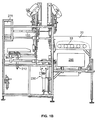
- the apparatus 2 as shown in FIGS. 1 , 2 , and 3 , is built with a frame 4 having a front 6, rear 8, left 10, and right 12. Attached to the frame are a product tube 30, a first iris plate 60, a moving iris plate 132, a tray 202, an orienter 216, a handle maker 230, a printer 260, an air supply 274, and electronic controls 276.
- a scale 16 is located apart from but close to the front of the frame 6.
- the product tube 30 is a cylinder, open at both ends, and is attached to the front of the frame 6.
- the product tube 30 is oriented to slope down slightly toward the rear 8, so that products, such as turkeys, placed in the upper end of the product tube 30 will slide by gravity the length of the product tube 30 and into the netting area of the apparatus 2, as explained below.
- a roller tray 32 is placed inside the product tube 30, to allow products, such as hams, to roll the length of the product tube 30 and into the netting area of the apparatus 2, as explained below.
- the product tube 30 contains a conveyor belt 33 to deliver the turkeys or hams to the netting area of the apparatus 2, as explained below.
- the product tube 30 is oval in cross-section and is of a sufficient height and width to accommodate the largest turkeys. Any suitable cross-section and size will suffice, depending on the material to be netted.
- the product tube 30 has two tube guides 34 and 36 located on the inside, to keep turkeys oriented in the proper direction as they slide the length of the product tube 30. Similar tube guides can be used for other products.
- a product tube circular in cross-section can be used for cylindrical products such as sausages.
- a roller tray, robotic arms, or any other means of delivering the materials to be encased into the apparatus 2 can be used.
- the netting 38 used for packaging material can be a hard but flexible plastic or natural fibers or other material. It is manufactured in a cylindrical shape and rolled into a torus. One end of the roll of netting 38 is clipped to close it and the roll is then placed around the outside of the product tube 30.
- a brake ring 14 is used to hold the netting 38 in place.
- the brake ring 40 comprises a flexible cable, attached to an air cylinder, and surrounding the netting 3 8 on the product tube 30. The air cylinder actuates to tighten the cable to hold the netting 38 snugly to the product tube 30, or releases to loosen the cable around the netting 38.
- the air cylinder actuates, tightening the cable, and providing resistance to further unfurling of the netting 38.
- the air cylinder shuts off after the turkey has been clipped, as later explained, loosening the cable and freeing the netting 38 for unfurling by the next turkey.
- the brake ring 14 is a flexible rubber hose, attached to an air supply, surrounding the product tube 30 to hold the netting 38 in place. A simple rubber band can also be used to hold the netting about the product tube.
- the product tube 30 leads to a first iris plate 60.
- the first iris plate 60 shown in more detail in FIG. 4 , comprises a vertically oriented sheet of material containing a first iris 62.
- the first iris 62 comprises three separators 64a, 64b, and 64c, which are actuated by a first iris separator cylinder 66.
- a first iris left gate assembly 68 and a first iris right gate assembly 72 are attached to the rear of the first iris plate, as shown in FIG. 5 . These two gate assemblies are actuated by a first iris left gate cylinder 70 and a first iris right gate cylinder 74.
- the three separators 64a, 64b, and 64c operate like a camera lens, to open to allow material, such as a turkey, to pass through it, and to close to gather the netting 38.
- the first iris left gate assembly 68 and the first iris right gate assembly 72 rotate inwardly to further gather the netting 38 and retract to allow material, such as a turkey, to pass through the first iris 62.
- FIG. 5 shows the first iris left gate assembly 68 and a first iris right gate assembly 72 rotated inward to the closed position.
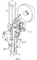
- a first clipper 102 shown in FIG. 5 , is attached to the first iris plate 60.
- the first clipper 102 is actuated by a first clipper main cylinder 104 and has a first clipper die support 106.
- a scissors assembly 300 is also attached to the first iris plate 60 and is actuated by a scissors cylinder 302.
- the first clipper 102 clips the netting 3 8 after it has been gathered by the first iris 62 and the first iris left gate assembly 68 and the first iris right gate assembly 72.
- the scissors assembly 300 severs the netting 38 after it has been clipped.
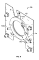
- a moving iris plate 132 To the rear of the first iris plate is a moving iris plate 132, shown in FIG. 6 .
- the moving iris plate 132 is moved by a moving iris plate cylinder 134.
- the moving iris plate 132 travels along four traveling rods 148a, 148b, 148c, and 148d, which are attached to the first iris plate 60 and to the frame 4, so that the moving iris plate 132 is always parallel to the first iris plate 60.
- the moving iris plate 132 comprises a vertically oriented sheet of material containing a moving iris 130.
- the moving iris 130 comprises three separators 136a, 136b, and 136c, and operates like a camera lens, to open to allow material, such as a turkey, to pass through it, and to close to gather the netting 38.
- the separators 136a, 136b, and 136c are actuated by a moving iris separator cylinder 134.
- an opening must be 35,6cm (14 inches) in diameter.
- the use of three separators 136a, 136b, and 136c in the moving iris 130 and three separators 64a, 64b, and 64c in the first iris 62 allows for use of actuating cylinders 66 and 138 with only a 10,2cm (four-inch) movement, which can be operated quickly to achieve high production rates.
- a moving iris left gate assembly 140 and a moving iris right gate assembly 144 are attached to moving iris plate 132 at the front of the moving iris 130, as shown in FIG. 7 .
- These two gate assemblies 140 and 144 are actuated by a moving iris left gate cylinder 142 and a moving iris right gate cylinder 146.
- the moving iris left gate assembly 140 and a moving iris right gate assembly 144 operate in the same manner as described above for the first iris plate 60: the moving iris left gate assembly 140 and a moving iris right gate assembly 144 rotate inward to gather the netting and rotate outward to allow material, such as a turkey, to pass through the moving iris 130.
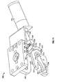
- a second clipper 160 shown in FIG. 7 , is attached to the moving iris plate 132.
- the second clipper 160 is actuated by a second clipper cylinder 164 and contains a die support 166.
- the second clipper 160 clips the netting 38 after it has been gathered by the moving iris 130 and the moving iris left gate assembly 140 and a moving iris right gate assembly 144.
- the second clipper 160 clips the netting after it has been gathered and after the handle maker 230, described below, has formed a loop in the netting 38.
- the second clipper 160 contains a reel brake 162 to hold the clips tightly and to prevent shaking of the clips as the second clipper 160 travels.
- the tray 202 To the rear of the moving iris plate 132 is the tray 202, shown in FIG. 8 .
- the tray 202 is mounted to the traveling rods 148a, 148b, 148c, and 148d and moves in a front to rear direction, actuated by a tray cylinder 204.
- Mounted on top of the tray 202 is a dump tray 206, which is actuated by a dump tray cylinder 212.
- the dump tray 206 is sized to accommodate the material being netted.
- the dump tray 206 contains a dump tray eye that senses when material arrives on the dump tray 206.
- the dump tray 206 contains two pan flanges, to control the orientation of the turkey on the dump tray 206.
- the dump tray 206 protrudes through the moving iris 130 and the first iris 62, which are open.
- Material such as a turkey, slides down the product tube 3 0, either by gravity feed or by direct delivery on a conveyor, contacts the closed end of the roll of netting 38, moves through the first iris 62 and the moving iris 130, pulling the netting 38 along, and lands on the dump tray 206.
- the moving iris 130 and the first iris 62 then close to gather the netting 38 as described above.
- the tray 202 then retracts to the rear, taking along the dump tray 206 and the turkey, and slightly tightening the netting 38 around the turkey.
- the handle maker 230 shown in FIG. 9 , is comprised of a handle maker clamp 232, a rotating cylinder 234, a clamping cylinder 236, a lifting cylinder 238, a first prox switch 240, a second prox switch 242, and a vacuum assembly 262.
- the handle maker 230 is located just to the rear and just below the first iris plate 60.
- the rotating cylinder 234 causes the handle maker clamp 232 to rotate in a horizontal plane.
- the lifting cylinder 238 causes the handle maker 230 to arise and descend vertically.
- the clamping cylinder 236 causes the handle maker clamp 232 to open and close.
- the two prox switches 240 and 242 sense the location and limits of movement of the handle maker clamp 232.
- the handle maker 230 ascends after the netting 38 has been gathered and the netting 38 is stretched inside the open handle maker clamp 232.
- the handle maker clamp 232 when actuated, closes to grasp the netting 38.
- the handle maker 230 rotates, actuated by the rotating cylinder 234, to form a loop in the netting 38.
- the second clipper 160 then clips the netting 38 to close the netting around the turkey and to form a handle in the netting 38.
- the printer 260 is located below the product tube 30. It is a standard printer of any suitable manufacture, so long as it is capable of printing labels 266.
- the labels 266, shown in FIG. 10 comprise a label body 268, a label neck 270, and a perforation 272.
- a tag clamp 264 grabs a label 266 as it exits the printer 260, pulls on the label 266 to tear it at the perforation 272, and places the label 266 on top of the handle maker clamp 232.
- a vacuum assembly 262 holds the label 266 in place.
- the label neck 270 protrudes next to the netting 38.
- the second clipper 160 when it clips the netting as described above, clips both netting 38 and the label neck 270, so that the label 266 is securely fastened to the package.
- the scale is placed at a convenient location near the front of the frame 6.
- the scale communicates with the printer 260 through a scale cable 18.
- the weight of the material such as a turkey, is transmitted to the printer 260.
- the printer 260 prints the label 266, it can add the weight of the turkey as well as any other data that is desired.
- An electronic control 276 monitors and operates the apparatus 2 by controlling the various cylinders.
- the electronic control is a standard Siemens central processing unit, with a "power 5 6EP1333-1SL11" power supply, a "Simatic S7-300 314-1AE04-0AB0" PLC, a 32-output "SM322 321-1BL00-0AA0” card, a 32-input "SM321321-ABL00-0AA0" card, and a 16-input "SM 321321-1BH0S-0AA0" card.
- a Banner Machine Safety GM-FA-10J module monitors and controls all limit switches.
- the clippers 102 and 160 have unique features. To achieve the objects of the invention, the clippers 102 and 160 must have long gates, the cylinders 104 and 164 must be offset to the side instead of being right over the clip channel (to save room), the punch holder must be offset to the center line of the punch (to shorten the height of the apparatus 2 in order to fit into standard rooms), and the punch, which is a standard wear item, must be able to be changed in about one minute, instead of the usual 30 minutes change time.
- the netting 38 is placed over the product tube 30.
- the netting 38 is clipped in a standard manner, at the rear of the product tube 3 0.
- both irises 62 and 130 are open, the moving iris plate 132 is moved to its most forward position, just behind the first iris plate 60, the tray 202 has moved to its most forward position, and the dump tray 206 protrudes through the eyes of each of the irises 62 and 130.
- the handle maker 230 is at its recessed or most downward position.
- the material to be netted such as a dressed and wrapped turkey, is placed on the scale 16.
- the scale 16 weighs the product and transmits this data to the printer 260.
- the printer 260 prints a label 266 with whatever data is required, such as weight, cost per pound, and total cost.
- the printer 96 ejects the label 266, whereupon the tag clamp 264 grasps the label 266, tears it at the perforation 272, and places it on the handle maker clamp 232.
- the vacuum assembly 262 draws a slight vacuum through two small holes on the handle maker clamp 232, to keep the label 266 in place.
- the operator takes the turkey off the scale and places it in the product tube 30.
- the turkey slides down the product tube 30, maintaining its orientation by virtue of the product guides 34 and 36. If it fails to slide, a slight push by the operator will propel it. For this reason, the product tube is longer than a person's arm, to keep the operator's hands out of any moving parts.
- a conveyor 33 is used, then the turkey is conveyed directly to netting area. The turkey slides against the clipped end of the netting 38, through the first iris 62 and the moving iris 130, and onto the dump tray 206.
- the dump tray eye 214 senses the arrival of the turkey and signals the electronic control 276. Since the end of the netting 38 had been clipped, the turkey pulls the netting 38 along with it.
- the brake ring 14 prevents the netting 38 from unrolling too much and maintains a slight amount of tension on the netting 38.
- the tray 202 then moves toward the rear, taking, of course, the dump tray 206 and the turkey with it, moving an amount sufficient to clear both irises 62 and 130.
- the orienter 216 now descends and pushes down on the turkey. If the turkey is askew, the orienter 216 forces the legs of the turkey to point toward the front 6, as that is where the handle will be applied. Both irises 62 and 130 close, somewhat gathering the netting 38.
- the orienter 216 then ascends back to its original position.
- the moving iris plate 132 and the tray 202 then move to the rear, pulling the netting 38 through the now-closed moving iris 130 and tautening the netting 38 around the turkey. Please note that the traveling components, the moving iris plate 132 and the tray 202, only move as far to the rear as is necessary, and merely make the netting 38 snug around the turkey, not tight.
- the handle maker 230 now rises and the handle maker clamp 232 closes, grasping the netting 38.
- the first iris left gate assembly 68 and first iris right gate assembly 72 rotate toward the center of the first iris 62, further grasping the netting 38.
- the first clipper 102 now fires to clip the netting 3 8 at the point where it is grasped in the center of the first iris 62. As soon as the first clipper 102 fires, the scissors assembly 300 severs the netting 38 just to the rear of the newly-applied clip.
- the handle maker 230 now rotates 180 degrees horizontally to make a loop out of the gathered netting 38.
- the moving iris plate 132 moves forward slightly, about 12,7cm (five inches) in order to provide enough slack for the handle maker clamp 232 to rotate.
- the handle maker 230 rotates, it pulls the netting 38 tightly around the turkey. This step allows the apparatus 2 to accommodate any size of turkey and still obtain a tight fit of netting 38.
- the moving iris left gate assembly 140 and moving iris right gate assembly 144 rotate toward the center of the moving iris 130, further grasping the netting 38.
- the netting 38 is now gathered by the moving iris 130 and by the moving iris left and right gate assemblies 140 and 144, so that the netting 38 tightly encloses the turkey, then forms a loop around the handle maker clamp 232 and extends back in between the moving iris left and right gate assemblies 140 and 144 to form a loop.
- the neck 270 of the label 266 also extends into this same area.
- the second clipper 160 now fires, clipping the netting 38 and label 266 together.
- the handle maker clamp 232 then descends to its original, downward position and rotates back to its original orientation, the tray 202 and the moving iris plate 132 move to the most rearward position, all gate assemblies 68, 72, 140, and 144 rotate back to their original, open positions, and both irises 62 and 130 open.
- the dump tray 206 then rotates to the right, dumping the now-netted turkey out of the apparatus 2.
- the dump tray 206 then retracts to its original, level position and the tray 202 and moving iris plate 132 move forward to their original positions.
- the dump tray 206 then moves forward into its original position inside the now-open irises 62 and 130.
- the apparatus 2 is now ready for another turkey.
- the dump tray 206 can dump the netted turkey out either the left or right side of the apparatus 2, or even out the rear, depending on the user's needs.
- the handle maker step can be eliminated if no handle is desired, or the label step can be eliminated if no label is desired.
- Scissors assembly 300 is attached to first clipper 102, as shown in FIG. 5 , and is shown in perspective view in FIG. 11 , in top view in FIG. 12 , and in plan view in FIG. 13 .
- Scissors assembly 300 has a pair of scissor blades 304, 306.
- Top scissors blade 304 has a front knife section 310 and a rear lever section 312.
- Link arm 314 is attached at its first end 316 to rear lever section 312 at pin 318.
- Bottom scissors blade 306 has a front knife section 320 and a rear lever section 322.
- a link arm 324 is attached at its first end 326 to rear lever section 322 at axle 328.
- Top scissors blade 304 and bottom scissors blade 306 are connected at and rotate about pin 330, which extends axially from die support 332.
- Die support 332 is affixed to first clipper 102 as shown in FIG. 5 . Accordingly, knife sections 310, 320 extend in a first direction from pin 330 and lever sections 322, 312 extend in a second direction from pin 330.
- a second end 317 of link arm 314 and a second end 327 of link arm 324 are connected to shackle 334 through pin 336.
- Shackle 334 is affixed to piston 338 of cylinder 302.
- Cylinder 302 is preferably an air-actuated cylinder, controlled in the same manner as the other air cylinders of the apparatus 2, as described above. Any other means of providing back-and-forth motion are acceptable.
- actuation of cylinder 302 causes piston 338 to extend.
- This extension causes lever section 312 and lever section 322 to rotate about pin 330 in opposite directions, as pushed by link arm s 314, 324.
- knife sections 310, 320 are brought together, severing the netting 38. Because there are two knife edges, from the two knife sections 310, 320, the netting is severed cleanly, as compared to the prior art in which a single knife edge attempted to sever the netting.
- cylinder 302 de-actuates to withdraw piston 338. Accordingly, in the reverse of the process described above, knife sections 310, 320 separate and wait for the next step in the procedure.
- Scissors assembly 300 is more easily maintained than the single-knife of the prior art. As the knife edges of the two blades 310, 320 slice next to each other, rather than at each other, they are less likely to become dull and will need to be sharpened less often.
- Scissors assembly 300 is described as part of an automated netter. The same scissors assembly 300, however, can be used as part of a clipper in a manual netting apparatus. Furthermore, scissors assembly 300 can be used in any apparatus requiring a clean severance of netting, such as with the production of netted sausage.
Landscapes
- Engineering & Computer Science (AREA)
- Mechanical Engineering (AREA)
- Auxiliary Devices For And Details Of Packaging Control (AREA)
Abstract
Description
- This invention is generally directed to a system for enclosing materials, such as poultry, hams or other materials, in netting and applying a handle and a label to the package. Such an apparatus is discloses in
US 2004/0068964 A1 . - The food industry often wishes to place products in nets. For example, large fowl, particularly turkeys, are encased in a plastic, see-through wrapper, for sanitary reasons, and then enclosed in netting for package integrity and ease of handling. The netting provides a strong structure to hold the turkey and allows the consumer to see the packaged material. It is important that the netting be tight around the package, to provide a pleasing appearance to consumers. There is a marketing advantage to having tightly-netted packages.
- Nets are also applied to other food products, such as poultry, hams, sausages, or cheeses, prior to further processing, such as smoking.
- In many cases, a handle is also applied to the package. Sausages and hams are enclosed in netting prior to cooking or smoking. The use of a handle is mandated, as there must be some way to handle the product in the cooking or smoking apparatus. The handles on these products are generally discarded after processing.
- The handle is also useful to workers and customers in retail establishments, especially when the product is frozen, to make it easier to grab the product. A handle facilitates maneuvering the products, such as moving the products in and out of display cases, through check-out lanes, or in and out of the consumer's own refrigerator or freezer. Additionally, some consumers prefer to use a handle in order to avoid touching the package itself. Accordingly, there is a marketing advantage to having a handle on the product. In the case of turkeys or other poultry, it is important that the handle be applied at the rear-most point of the birds, which is where the legs point, to provide a pleasing appearance to purchasers.
- Most of the same products also have a label of some type applied to the product. The label displays such data as weight, price per unit of weight, and total price. Other data, such as lot numbers, batch identification, product identification, or expiration date, are also common. The label can also contain identification information such as brand names or logos.
- Netting is manufactured in a long, continuous tube, usually of a hard thermoplastic but also from natural fibers. The prior art method of enclosing a turkey in netting was to clip one end of the netting tube, place the turkey in the tube, manually pull the netting tightly around the turkey, clip the open end to enclose the turkey in the netting, and cut the netting. If a handle was desired, the additional step was, after the netting was pulled around the turkey, to form a loop while holding the netting tightly against the turkey, clip the netting at the close of the loop, and cut the netting.
- This prior art method was labor intensive. Additionally, it was difficult to obtain uniform tightness of netting. Additionally, the method requires quite a bit of manual pulling and wrapping, making hand fatigue and injuries common.
- Prior art methods to automate the process have been unsuccessful. One method used clippers built into gathering plates, but that method was awkward and slow because the gathering plates had to move. Since an opening must be at least 35,6cm (14 inches) to accommodate the largest turkeys, the gathering plates had to move at least 17,8cm (seven inches) and, to be practical, had to move more like 25,4cm (10 inches). Accordingly, they were big, heavy, and slow. The prior art automated processes also worked only for consistently-sized turkeys. Application of a predetermined length of netting had to be based on the largest turkeys available. If the predetermined length of netting was sufficient to enclose the largest turkeys, however, all smaller turkeys would be netted loosely, which caused a marketing disadvantage.
- Clippers as known in the prior art used a knife edge to sever the netting. For woven netting, if the knife edge does not completely sever all strands of the netting, a trailing strand of netting will hang from the clipped end of the package. Additionally, incomplete severing of the netting can cause strands of woven netting to pull through the netting, leaving a trailing strand. This problem occurs most frequently with netting made from natural fibers, especially cotton, but the problem also arises with netting made from other materials. This problem arises in automated netters, such as the one described herein, as well as in manual netters described above.
- These trailing edges cause contamination problems in, for example, smokehouses. Packaged and netted food products, such as hams, turkeys, cheeses, and sausages, are often hung on racks and moved from a packaging room to a smokeroom. It is paramount to prevent cross-contamination between the two rooms. Although the smoking process will kill some bacteria, other bacteria thrive on heat and will multiply rapidly in a smokeroom. Accordingly, the racks are usually suspended from tracks hung from the ceiling, so there are no wheels to pick up bacteria from the floor of the packaging room. Additionally, workers pushing the racks from the packaging room to the smokeroom, or otherwise traveling between the two rooms, are required to step through a bleach trough, to remove any contamination from their shoes.
- If there are strands of netting hanging from the products suspended on the racks, those strands can drag on the floor of the packaging room and likely will pick up bacterial contamination. That contamination can travel up the strand, especially with netting made from natural fibers. The bleach trough may not completely remove this contamination.
- To solve this problem, food processors station an extra employee between the packaging room and the smokeroom, to sever any trailing strands of netting with scissors. This method adds to the labor cost of an otherwise highly-automated process.
- Accordingly, there is a need for an apparatus of encasing material such as turkeys or hams, in netting, that will reduce labor costs by reducing the amount of labor required, easing the tasks of the workers that are required, provide a pleasing appearance to consumers, and prevent contamination of food products during processing such as smoking. There is also a need for an apparatus of encasing material such as turkeys or hams, in netting, that will provide a loop in the netting to act as a handle, for subsequent processing or for consumer use. There is also a need for an apparatus of applying a label with identifying data, as part of the same netting process. The present invention as defined in claim 1 meets these needs.
- The present invention discloses an apparatus to insert material such as a turkey into netting, to pull the netting tightly around the material, to form a loop at one end for carrying the material, to completely sever the netting by the use of scissors, and to apply a label with data concerning the material. The apparatus and method described accomplish this purpose, and allow for encasing not just whole turkeys but also turkey breasts, hams, sausages, cheeses, and any other materials which one might desire to place in netting. The method and apparatus provide for pulling the netting tight by machinery, instead of by hand, easing the task of the worker and providing for a uniformly tight appearance.
- The apparatus comprises a product tube, a first clipper with a scissors assembly, a handle-maker, and a second clipper. The apparatus places the material to be enclosed in a continuous cylinder of netting, previously clipped on one end. The apparatus pulls the material through two irises, pulling the netting about the material. The two irises then close, gathering the netting. One iris moves away, tightening the netting about the material. The handle maker grasps the gathered netting, pulling it tightly around the material, and further makes a loop. The first clipper clips the netting and also severs it with scissors. The second clipper clips the loop adjacent the material, to enclose the material in a tight net with a looped handle. The second clipper also clips a label to the loop, for product information.
- The organization and manner of the structure and operation of the invention, together with further obj ects and advantages thereof, may best be understood by reference to the following description, taken in connection with the accompanying drawings:
-
FIG. 1 is a front perspective view of the apparatus of the an embodiment of the present invention. -
FIG. 1A is a front perspective view of the apparatus of another embodiment of the present invention. -
FIG. 1B is an elevation view of the product tube of one embodiment of the present invention, showing in cut-out view the conveyor. -
FIG. 2 is an elevation view of the apparatus of the preferred embodiment of the present invention. -
FIG. 3 is a rear perspective view of the apparatus of the preferred embodiment of the present invention. -
FIG. 4 is a view of the first iris plate of the apparatus of the preferred embodiment of the present invention. -
FIG. 5 is a view of the first clipper of the apparatus of the preferred embodiment of the present invention. -
FIG. 6 is a view of the moving iris plate of the apparatus of the preferred embodiment of the present invention. -
FIG. 7 is a view of the second clipper of the apparatus of the preferred embodiment of the present invention. -
FIG. 8 is a view of the dump tray of the apparatus of the preferred embodiment of the present invention. -
FIG. 9 is a view of the handle maker of the apparatus of the preferred embodiment of the present invention. -
FIG. 10 is a view of sample labels of the preferred embodiment of the present invention. -
FIG. 11 is a perspective view of the scissors used in conjunction with the first clipper of the preferred embodiment of the present invention. -
FIG. 12 is a top view of the scissors used in conjunction with the first clipper of the preferred embodiment of the present invention. -
FIG. 13 is a plan view of the scissors used in conjunction with the first clipper of the preferred embodiment of the present invention. - While the invention may be susceptible to embodiments in different forms, there is shown in the drawings, and herein will be described in detail, a specific embodiment with the understanding that the present disclosure is to be considered an exemplification of the principles of the invention, and is not intended to limit the invention to that as illustrated and described herein. For example, the present disclosure describes the method and apparatus as used to encase whole turkeys. The same method and apparatus can be used for other whole poultry, for poultry parts, such as turkey breast, or for any other material that one may wish to enclose in netting, such as hams, sausages, cheeses, or other food or non-food products, without departure from the invention.
- The
apparatus 2, as shown inFIGS. 1 ,2 , and3 , is built with a frame 4 having afront 6, rear 8, left 10, and right 12. Attached to the frame are aproduct tube 30, afirst iris plate 60, a movingiris plate 132, atray 202, an orienter 216, ahandle maker 230, aprinter 260, an air supply 274, andelectronic controls 276. Ascale 16 is located apart from but close to the front of theframe 6. - The
product tube 30 is a cylinder, open at both ends, and is attached to the front of theframe 6. In one embodiment, theproduct tube 30 is oriented to slope down slightly toward the rear 8, so that products, such as turkeys, placed in the upper end of theproduct tube 30 will slide by gravity the length of theproduct tube 30 and into the netting area of theapparatus 2, as explained below. In another embodiment, a roller tray 32 is placed inside theproduct tube 30, to allow products, such as hams, to roll the length of theproduct tube 30 and into the netting area of theapparatus 2, as explained below. In another embodiment, theproduct tube 30 contains aconveyor belt 33 to deliver the turkeys or hams to the netting area of theapparatus 2, as explained below. - In the preferred embodiment, the
product tube 30 is oval in cross-section and is of a sufficient height and width to accommodate the largest turkeys. Any suitable cross-section and size will suffice, depending on the material to be netted. In the gravity-feed embodiment, theproduct tube 30 has two tube guides 34 and 36 located on the inside, to keep turkeys oriented in the proper direction as they slide the length of theproduct tube 30. Similar tube guides can be used for other products. Alternatively, a product tube circular in cross-section can be used for cylindrical products such as sausages. A roller tray, robotic arms, or any other means of delivering the materials to be encased into theapparatus 2 can be used. - The netting 38 used for packaging material can be a hard but flexible plastic or natural fibers or other material. It is manufactured in a cylindrical shape and rolled into a torus. One end of the roll of netting 38 is clipped to close it and the roll is then placed around the outside of the
product tube 30. A brake ring 14 is used to hold the netting 38 in place. In the preferred embodiment, thebrake ring 40 comprises a flexible cable, attached to an air cylinder, and surrounding the netting 3 8 on theproduct tube 30. The air cylinder actuates to tighten the cable to hold the netting 38 snugly to theproduct tube 30, or releases to loosen the cable around the netting 38. After material such as a turkey has traveled down theproduct tube 30, contacted the netting 38, and landed on thedump tray 206, as later explained, the air cylinder actuates, tightening the cable, and providing resistance to further unfurling of the netting 38. The air cylinder shuts off after the turkey has been clipped, as later explained, loosening the cable and freeing the netting 38 for unfurling by the next turkey. In another embodiment, the brake ring 14 is a flexible rubber hose, attached to an air supply, surrounding theproduct tube 30 to hold the netting 38 in place. A simple rubber band can also be used to hold the netting about the product tube. - The
product tube 30 leads to afirst iris plate 60. Thefirst iris plate 60, shown in more detail inFIG. 4 , comprises a vertically oriented sheet of material containing afirst iris 62. Thefirst iris 62 comprises threeseparators iris separator cylinder 66. A first iris leftgate assembly 68 and a first irisright gate assembly 72 are attached to the rear of the first iris plate, as shown inFIG. 5 . These two gate assemblies are actuated by a first iris leftgate cylinder 70 and a first irisright gate cylinder 74. The threeseparators gate assembly 68 and the first irisright gate assembly 72 rotate inwardly to further gather the netting 38 and retract to allow material, such as a turkey, to pass through thefirst iris 62.FIG. 5 shows the first iris leftgate assembly 68 and a first irisright gate assembly 72 rotated inward to the closed position. - A
first clipper 102, shown inFIG. 5 , is attached to thefirst iris plate 60. Thefirst clipper 102 is actuated by a first clippermain cylinder 104 and has a firstclipper die support 106. Ascissors assembly 300 is also attached to thefirst iris plate 60 and is actuated by ascissors cylinder 302. Thefirst clipper 102 clips the netting 3 8 after it has been gathered by thefirst iris 62 and the first iris leftgate assembly 68 and the first irisright gate assembly 72. Thescissors assembly 300 severs the netting 38 after it has been clipped. - To the rear of the first iris plate is a moving
iris plate 132, shown inFIG. 6 . The movingiris plate 132 is moved by a movingiris plate cylinder 134. The movingiris plate 132 travels along four travelingrods first iris plate 60 and to the frame 4, so that the movingiris plate 132 is always parallel to thefirst iris plate 60. - The moving
iris plate 132 comprises a vertically oriented sheet of material containing a movingiris 130. The movingiris 130 comprises threeseparators separators iris separator cylinder 134. - To accommodate the largest turkeys, an opening must be 35,6cm (14 inches) in diameter. The use of three
separators iris 130 and threeseparators first iris 62 allows for use of actuatingcylinders 66 and 138 with only a 10,2cm (four-inch) movement, which can be operated quickly to achieve high production rates. - A moving iris left
gate assembly 140 and a moving irisright gate assembly 144 are attached to movingiris plate 132 at the front of the movingiris 130, as shown inFIG. 7 . These twogate assemblies gate cylinder 142 and a moving irisright gate cylinder 146. The moving iris leftgate assembly 140 and a moving irisright gate assembly 144 operate in the same manner as described above for the first iris plate 60: the moving iris leftgate assembly 140 and a moving irisright gate assembly 144 rotate inward to gather the netting and rotate outward to allow material, such as a turkey, to pass through the movingiris 130. - A
second clipper 160, shown inFIG. 7 , is attached to the movingiris plate 132. Thesecond clipper 160 is actuated by asecond clipper cylinder 164 and contains adie support 166. Thesecond clipper 160 clips the netting 38 after it has been gathered by the movingiris 130 and the moving iris leftgate assembly 140 and a moving irisright gate assembly 144. When a handle is desired on the package, thesecond clipper 160 clips the netting after it has been gathered and after thehandle maker 230, described below, has formed a loop in the netting 38. Note that, in the preferred embodiment, thesecond clipper 160 contains areel brake 162 to hold the clips tightly and to prevent shaking of the clips as thesecond clipper 160 travels. - To the rear of the moving
iris plate 132 is thetray 202, shown inFIG. 8 . Thetray 202 is mounted to the travelingrods tray cylinder 204. Mounted on top of thetray 202 is adump tray 206, which is actuated by adump tray cylinder 212. Thedump tray 206 is sized to accommodate the material being netted. In one embodiment, thedump tray 206 contains a dump tray eye that senses when material arrives on thedump tray 206. In another embodiment, thedump tray 206 contains two pan flanges, to control the orientation of the turkey on thedump tray 206. - When the
tray 202 is in its most forward position, thedump tray 206 protrudes through the movingiris 130 and thefirst iris 62, which are open. Material, such as a turkey, slides down the product tube 3 0, either by gravity feed or by direct delivery on a conveyor, contacts the closed end of the roll of netting 38, moves through thefirst iris 62 and the movingiris 130, pulling the netting 38 along, and lands on thedump tray 206. The movingiris 130 and thefirst iris 62 then close to gather the netting 38 as described above. Thetray 202 then retracts to the rear, taking along thedump tray 206 and the turkey, and slightly tightening the netting 38 around the turkey. - The
handle maker 230, shown inFIG. 9 , is comprised of ahandle maker clamp 232, arotating cylinder 234, aclamping cylinder 236, alifting cylinder 238, afirst prox switch 240, asecond prox switch 242, and avacuum assembly 262. Thehandle maker 230 is located just to the rear and just below thefirst iris plate 60. Therotating cylinder 234 causes thehandle maker clamp 232 to rotate in a horizontal plane. Thelifting cylinder 238 causes thehandle maker 230 to arise and descend vertically. Theclamping cylinder 236 causes thehandle maker clamp 232 to open and close. The twoprox switches handle maker clamp 232. - The
handle maker 230 ascends after the netting 38 has been gathered and the netting 38 is stretched inside the openhandle maker clamp 232. Thehandle maker clamp 232, when actuated, closes to grasp the netting 38. After thefirst clipper 102 has clipped the netting 3 8 and the knife 108 has severed the netting 38, thehandle maker 230 rotates, actuated by therotating cylinder 234, to form a loop in the netting 38. Thesecond clipper 160 then clips the netting 38 to close the netting around the turkey and to form a handle in the netting 38. - The
printer 260 is located below theproduct tube 30. It is a standard printer of any suitable manufacture, so long as it is capable of printing labels 266. Thelabels 266, shown inFIG. 10 , comprise alabel body 268, alabel neck 270, and aperforation 272. Atag clamp 264 grabs alabel 266 as it exits theprinter 260, pulls on thelabel 266 to tear it at theperforation 272, and places thelabel 266 on top of thehandle maker clamp 232. Avacuum assembly 262 holds thelabel 266 in place. When alabel 266 is desired, thelabel neck 270 protrudes next to the netting 38. Thesecond clipper 160, when it clips the netting as described above, clips both netting 38 and thelabel neck 270, so that thelabel 266 is securely fastened to the package. - The scale is placed at a convenient location near the front of the
frame 6. The scale communicates with theprinter 260 through ascale cable 18. The weight of the material, such as a turkey, is transmitted to theprinter 260. When theprinter 260 prints thelabel 266, it can add the weight of the turkey as well as any other data that is desired. - All moving parts are actuated by air cylinders as described above. Each air cylinder is connected to a standard air supply (not shown). An
electronic control 276 monitors and operates theapparatus 2 by controlling the various cylinders. In the preferred embodiment, the electronic control is a standard Siemens central processing unit, with a "power 5 6EP1333-1SL11" power supply, a "Simatic S7-300 314-1AE04-0AB0" PLC, a 32-output "SM322 321-1BL00-0AA0" card, a 32-input "SM321321-ABL00-0AA0" card, and a 16-input "SM 321321-1BH0S-0AA0" card. - All moving parts are enclosed by doors (not shown) with limit switches (not shown) to sense the position of the doors. For safety, the entire apparatus will stop all movement if a door is opened. In the preferred embodiment, a Banner Machine Safety GM-FA-10J module monitors and controls all limit switches.
- Please note that the
clippers clippers cylinders apparatus 2 in order to fit into standard rooms), and the punch, which is a standard wear item, must be able to be changed in about one minute, instead of the usual 30 minutes change time. - To begin operation of the
apparatus 2, the netting 38 is placed over theproduct tube 30. The netting 38 is clipped in a standard manner, at the rear of the product tube 3 0. At this point, bothirises iris plate 132 is moved to its most forward position, just behind thefirst iris plate 60, thetray 202 has moved to its most forward position, and thedump tray 206 protrudes through the eyes of each of theirises handle maker 230 is at its recessed or most downward position. - The material to be netted, such as a dressed and wrapped turkey, is placed on the
scale 16. Thescale 16 weighs the product and transmits this data to theprinter 260. Theprinter 260 prints alabel 266 with whatever data is required, such as weight, cost per pound, and total cost. The printer 96 ejects thelabel 266, whereupon thetag clamp 264 grasps thelabel 266, tears it at theperforation 272, and places it on thehandle maker clamp 232. Thevacuum assembly 262 draws a slight vacuum through two small holes on thehandle maker clamp 232, to keep thelabel 266 in place. - In the meantime, the operator takes the turkey off the scale and places it in the
product tube 30. In the gravity feed embodiment, because of the downward slant of theproduct tube 30, the turkey slides down theproduct tube 30, maintaining its orientation by virtue of the product guides 34 and 36. If it fails to slide, a slight push by the operator will propel it. For this reason, the product tube is longer than a person's arm, to keep the operator's hands out of any moving parts. If aconveyor 33 is used, then the turkey is conveyed directly to netting area. The turkey slides against the clipped end of the netting 38, through thefirst iris 62 and the movingiris 130, and onto thedump tray 206. The dump tray eye 214 senses the arrival of the turkey and signals theelectronic control 276. Since the end of the netting 38 had been clipped, the turkey pulls the netting 38 along with it. The brake ring 14 prevents the netting 38 from unrolling too much and maintains a slight amount of tension on the netting 38. - The
tray 202 then moves toward the rear, taking, of course, thedump tray 206 and the turkey with it, moving an amount sufficient to clear bothirises front 6, as that is where the handle will be applied. Both irises 62 and 130 close, somewhat gathering the netting 38. The orienter 216 then ascends back to its original position. The movingiris plate 132 and thetray 202 then move to the rear, pulling the netting 38 through the now-closed movingiris 130 and tautening the netting 38 around the turkey. Please note that the traveling components, the movingiris plate 132 and thetray 202, only move as far to the rear as is necessary, and merely make the netting 38 snug around the turkey, not tight. - The
handle maker 230 now rises and thehandle maker clamp 232 closes, grasping the netting 38. The first iris leftgate assembly 68 and first irisright gate assembly 72 rotate toward the center of thefirst iris 62, further grasping the netting 38. - The
first clipper 102 now fires to clip the netting 3 8 at the point where it is grasped in the center of thefirst iris 62. As soon as thefirst clipper 102 fires, thescissors assembly 300 severs the netting 38 just to the rear of the newly-applied clip. - The
handle maker 230 now rotates 180 degrees horizontally to make a loop out of the gathered netting 38. The movingiris plate 132 moves forward slightly, about 12,7cm (five inches) in order to provide enough slack for thehandle maker clamp 232 to rotate. When thehandle maker 230 rotates, it pulls the netting 38 tightly around the turkey. This step allows theapparatus 2 to accommodate any size of turkey and still obtain a tight fit of netting 38. - As soon as the
handle maker clamp 232 has rotated 180 degrees, as sensed by the prox switches 240 and 242, the moving iris leftgate assembly 140 and moving irisright gate assembly 144 rotate toward the center of the movingiris 130, further grasping the netting 38. The netting 38 is now gathered by the movingiris 130 and by the moving iris left andright gate assemblies handle maker clamp 232 and extends back in between the moving iris left andright gate assemblies neck 270 of thelabel 266 also extends into this same area. - The
second clipper 160 now fires, clipping the netting 38 andlabel 266 together. Thehandle maker clamp 232 then descends to its original, downward position and rotates back to its original orientation, thetray 202 and the movingiris plate 132 move to the most rearward position, allgate assemblies irises - The
dump tray 206 then rotates to the right, dumping the now-netted turkey out of theapparatus 2. Thedump tray 206 then retracts to its original, level position and thetray 202 and movingiris plate 132 move forward to their original positions. Thedump tray 206 then moves forward into its original position inside the now-open irises apparatus 2 is now ready for another turkey. - Please note that many variations can be made of this method without departing from the invention. For example, the
dump tray 206 can dump the netted turkey out either the left or right side of theapparatus 2, or even out the rear, depending on the user's needs. The handle maker step can be eliminated if no handle is desired, or the label step can be eliminated if no label is desired. -
Scissors assembly 300 is attached tofirst clipper 102, as shown inFIG. 5 , and is shown in perspective view inFIG. 11 , in top view inFIG. 12 , and in plan view inFIG. 13 . -
Scissors assembly 300 has a pair ofscissor blades Top scissors blade 304 has afront knife section 310 and arear lever section 312.Link arm 314 is attached at itsfirst end 316 torear lever section 312 atpin 318.Bottom scissors blade 306 has a front knife section 320 and arear lever section 322. Alink arm 324 is attached at itsfirst end 326 torear lever section 322 ataxle 328. -
Top scissors blade 304 andbottom scissors blade 306 are connected at and rotate aboutpin 330, which extends axially fromdie support 332. Diesupport 332 is affixed tofirst clipper 102 as shown inFIG. 5 . Accordingly,knife sections 310, 320 extend in a first direction frompin 330 andlever sections pin 330. - A second end 317 of
link arm 314 and a second end 327 oflink arm 324 are connected to shackle 334 throughpin 336.Shackle 334 is affixed topiston 338 ofcylinder 302. -
Cylinder 302 is preferably an air-actuated cylinder, controlled in the same manner as the other air cylinders of theapparatus 2, as described above. Any other means of providing back-and-forth motion are acceptable. In the preferred embodiment, actuation ofcylinder 302 causespiston 338 to extend. This extension causeslever section 312 andlever section 322 to rotate aboutpin 330 in opposite directions, as pushed by link arm s 314, 324. Aslever sections knife sections 310, 320 are brought together, severing the netting 38. Because there are two knife edges, from the twoknife sections 310, 320, the netting is severed cleanly, as compared to the prior art in which a single knife edge attempted to sever the netting. - Once the netting has been severed,
cylinder 302 de-actuates to withdrawpiston 338. Accordingly, in the reverse of the process described above,knife sections 310, 320 separate and wait for the next step in the procedure. -
Scissors assembly 300 is more easily maintained than the single-knife of the prior art. As the knife edges of the twoblades 310, 320 slice next to each other, rather than at each other, they are less likely to become dull and will need to be sharpened less often. -
Scissors assembly 300 is described as part of an automated netter. Thesame scissors assembly 300, however, can be used as part of a clipper in a manual netting apparatus. Furthermore,scissors assembly 300 can be used in any apparatus requiring a clean severance of netting, such as with the production of netted sausage. - While preferred embodiments of the present invention are shown and described, it is envisioned that those skilled in the art may devise various modifications of the present invention without departing from the scope of the appended claims.
Claims (19)
- An apparatus (2) for enclosing material in netting (38), comprising:means to receive netting (38), the netting having an open end and a closed end and to place material in the netting through the open end;first means (68) to gather the netting around said material, said first means to gather located adjacent to said means to receive;second means (132) to gather the netting around said material;means for moving said second means to gather relative to said first means to gather, whereby the netting is stretched between said first means to gather and said second means to gather;a handle maker (230) to form a loop from the stretched netting; and a second clipper (160) to close said loop at said second gathering means;wherein the apparatus is characterised by:a first clipper (162) comprising a scissors assembly (300) to close and sever the netting at said first means, to create a new closed end on the severed roll, the scissors assembly comprising:a pair of blade elements pivotally connected by an pin affixed to said netter; each of said pair of blade elements comprising a knife section extending in a first direction from said pin and a lever section extending in a second direction from said pin;a pair of link arms each connecting one of said lever sections of said pair of blade elements to a piston, said piston extendable in a first direction to pivot said knife sections of said blade elements toward each other and extendable in a second direction to pivot said knife sections of said blade elements away from each other.
- The apparatus of claim 1, further comprising means (260) for printing information on a label (266) and means for attaching said label to the netting.
- The apparatus of claim 2, further comprising a scale to measure a weight of said material and transmit said weight to said means for printing.
- An apparatus for enclosing material in a net as defined in claim 1, comprising:a frame (6);a product tube (30) carried by said frame, and adapted for receiving the netting and for maintaining the open end of the netting in an open position, the closed end of the netting being in a closed position, whereby the material to be enclosed can be conveyed from a first end of said product tube to engage said closed end of the netting at a second end of said product tube and unfurl a portion off the netting from said product tube (30);wherein said first means (68) to gather includes: a first iris (62) held by said frame (6) adjacent to said second end of said product tube (30) and adjustable from an open position forming an aperture larger than the material, to a substantially closed position, whereby the material and said portion of the engaged and unfurled netting can be conveyed from said second end of said product tube through said first iris aperture and whereby the first iris (62) gathers the engaged and unfurled netting in said substantially closed position; and said second means (132) to gather includes a second iris (132) mounted on said frame (6) and movable from a first position adjacent said first iris (62), to a second position remote from said first iris, said second iris being adjustable from an open position forming an aperture larger than the material, to a substantially closed position, whereby said second iris gathers the engaged and unfurled netting in said substantially closed position;a tray (202) mounted on said frame (6) and movable from a first position protruding through said first iris (62) and said second iris (132), to a second position remote from said first iris (62);wherein the first clipper is attached to said first iris (62) and positioned to clip the severed netting gathered by said first iris and said second iris when said second iris is in said second position remote from said first iris, to form said closed position of said second end of the net on said product tube and a gathered strand of net on the material;the loop is formed by a clamp (232) rotatably attached to said frame (6) to grasp the gathered strand and to rotate to form the loop in the gathered and severed netting; andthe loop is closed by a second clipper attached to said second iris and positioned to clip said loop to form the handle.
- An apparatus for enclosing material according to claim 4, comprising a net.
- The apparatus of claim 4 or claim 5, further comprising:a printer (260) to print data on a label (266);a tag clamp (264) attached to said frame (6) to place said label in said rotating clamp (232) whereby said second clipper (160) attaches said label to said handle.
- The apparatus of claim 6, further comprising a scale to weigh the material and wherein said data comprises a weight of the material.
- The apparatus of claim 4 or claim 5, further comprising a brake ring (14) on said product tube (30) to provide resistance to unfurling of said netting from said product tube.
- The apparatus of claim 8, wherein said brake ring comprises an air-actuated tightenable cable.
- The apparatus of claim 8, wherein said brake ring (14) comprises a flexible hose attached to an air supply.
- The apparatus of claim 8, wherein said brake ring (14) comprises a rubber band.
- The apparatus of claim 4 or claim 5, wherein said product tube (30) is slanted to convey the material by gravity from said first end of said product tube to said second end of said product tube.
- The apparatus of claim 4 or claim 5, wherein said product tube (30) is slanted to convey the material by gravity from said first end of said product tube to said second end of said product tube and through said aperture of said first iris and said aperture of said second iris.
- The apparatus of claim 4 or claim 5, further comprising a roller tray to convey the material from said first end of said product tube to said second end of said product tube (30).
- The apparatus of claim 4 or claim 5, further comprising a conveyor belt (33) to convey the material from said first end of said product tube to said second end of said product tube.
- The apparatus of claim 4 or claim 5, further comprising tube guides (34, 36) in said product tube (30) to orient the material.
- The apparatus of claim 4 or claim 5, further comprising means to remove said material from said tray.
- The apparatus of claim 4 or claim 5, further comprising means to rotate said tray.
- The apparatus of claim 18, wherein said piston comprises an air-actuated cylinder (302).
Priority Applications (1)
| Application Number | Priority Date | Filing Date | Title |
|---|---|---|---|
| PL06760328T PL1893494T3 (en) | 2005-05-25 | 2006-05-24 | Netting knife cutter |
Applications Claiming Priority (2)
| Application Number | Priority Date | Filing Date | Title |
|---|---|---|---|
| US11/136,998 US7216469B2 (en) | 2005-05-25 | 2005-05-25 | Netting knife cutter |
| PCT/US2006/020023 WO2006127770A2 (en) | 2005-05-25 | 2006-05-24 | Netting knife cutter |
Publications (3)
| Publication Number | Publication Date |
|---|---|
| EP1893494A2 EP1893494A2 (en) | 2008-03-05 |
| EP1893494A4 EP1893494A4 (en) | 2010-01-13 |
| EP1893494B1 true EP1893494B1 (en) | 2012-08-01 |
Family
ID=37452766
Family Applications (1)
| Application Number | Title | Priority Date | Filing Date |
|---|---|---|---|
| EP20060760328 Not-in-force EP1893494B1 (en) | 2005-05-25 | 2006-05-24 | Netting knife cutter |
Country Status (7)
| Country | Link |
|---|---|
| US (2) | US7216469B2 (en) |
| EP (1) | EP1893494B1 (en) |
| AU (1) | AU2006250081A1 (en) |
| CA (1) | CA2609153A1 (en) |
| ES (1) | ES2393272T3 (en) |
| PL (1) | PL1893494T3 (en) |
| WO (1) | WO2006127770A2 (en) |
Families Citing this family (6)
| Publication number | Priority date | Publication date | Assignee | Title |
|---|---|---|---|---|
| US7216469B2 (en) * | 2005-05-25 | 2007-05-15 | Poly-Clip System Corp. | Netting knife cutter |
| US10259135B2 (en) * | 2007-02-26 | 2019-04-16 | Pellenc (Societe Anonyme) | Chainsaw apparatus having lubricating system |
| FR2912948B1 (en) * | 2007-02-26 | 2010-02-12 | Pellenc Sa | CHAIN SAW COMPRISING A LUBRICATION DEVICE AND METHOD FOR IMPLEMENTING SAID LUBRICATION |
| CN201345837Y (en) * | 2008-12-31 | 2009-11-18 | 南京德朔实业有限公司 | Electric pruning shears |
| EP2716160B1 (en) | 2012-10-02 | 2015-07-29 | Poly-clip System GmbH & Co. KG | Casing brake assembly |
| US10011423B2 (en) * | 2015-08-17 | 2018-07-03 | Medline Industries, Inc. | Cutting apparatus and associated systems |
Family Cites Families (44)
| Publication number | Priority date | Publication date | Assignee | Title |
|---|---|---|---|---|
| US728068A (en) * | 1903-02-16 | 1903-05-12 | Wesley Young | Pneumatic pruning-shears. |
| US1508155A (en) | 1922-08-01 | 1924-09-09 | Jacob H Berg | Meat-food product and method of making same |
| US1505218A (en) | 1924-03-26 | 1924-08-19 | Sartore Laurence | Method of stuffing sausage casings |
| US1873286A (en) | 1929-11-04 | 1932-08-23 | Charles C Chase | Candy package |
| US2366909A (en) * | 1943-06-29 | 1945-01-09 | Charles J Johnson | Power actuated pruning shears |
| US3092952A (en) | 1959-11-24 | 1963-06-11 | Molnlycke Vafveri Aktiebolag | Machine for forming securing loops on sanitary napkins |
| US3115667A (en) * | 1960-08-05 | 1963-12-31 | Swift & Co | Poultry foot cutter |
| US3389533A (en) | 1966-02-09 | 1968-06-25 | Rheem Mfg Co | Packaging apparatus and method |
| US3499259A (en) | 1966-02-09 | 1970-03-10 | Rheem Mfg Co | Packaging apparatus and method |
| US3540184A (en) | 1967-08-28 | 1970-11-17 | Bemis Co Inc | Packaging method |
| US3893237A (en) * | 1973-08-03 | 1975-07-08 | Donald E Jahnke | Poultry cutter |
| DE2424979A1 (en) | 1974-05-22 | 1975-12-11 | Karl Schnell | DEVICE FOR SEALING ELASTIC PACKINGS, IN PARTICULAR TUBULAR COVERS |
| US3939628A (en) | 1974-07-26 | 1976-02-24 | E. I. Du Pont De Nemours & Company | Bag and package making method |
| US4107903A (en) | 1976-02-03 | 1978-08-22 | Wickersheim & Johne Maschinen-Und Verpackungsanlagen Gmbh | Fully automatic device for packing piece goods, in particular fruits |
| US4091595A (en) * | 1976-07-15 | 1978-05-30 | Filper Corporation | Netting bag machine and method |
| US4044450A (en) | 1976-10-12 | 1977-08-30 | Union Carbide Corporation | Apparatus and method for providing hanger-clip closures for casings |
| DE2700641C3 (en) | 1977-01-08 | 1979-09-20 | Herbert Dipl.-Ing. 6240 Koenigstein Niedecker | Packaging wrapper section having a hanger baptism and method and apparatus for attaching the same |
| US4190690A (en) | 1978-09-22 | 1980-02-26 | Gallaher, Kantlehner & Associates, Inc. | Manufacture of sealed-end tubular thermoplastic net bagging |
| US4247005A (en) | 1979-03-30 | 1981-01-27 | Bemis Company, Inc. | Package and packaging method |
| FR2463059A1 (en) | 1979-08-14 | 1981-02-20 | Empac Sa | Sack filler with clasp for net - has clamps for closing each end and filling chute above scale platform |
| US4551962A (en) | 1981-09-25 | 1985-11-12 | Teraoka Seiko Co., Ltd. | Weighing and packing apparatus |
| DE3363262D1 (en) * | 1982-06-02 | 1986-06-05 | Teepak Prod Nv | Method and apparatus for automatically making strands of sausages |
| IT1168656B (en) | 1983-03-25 | 1987-05-20 | Sorma Srl | AUTOMATIC EQUIPMENT FOR PACKAGING OF PACKAGING SCREENING WITH SUPPORT STRIPS AND LABELS ON CONTAINERS OF FRUITS AND VEGETABLES |
| US4675945A (en) | 1985-01-23 | 1987-06-30 | Tipper Tie, Inc. | Clipping apparatus |
| US4593516A (en) | 1985-02-04 | 1986-06-10 | Robert Alameda | Apparatus for forming tight packages |
| GB2190651B (en) | 1986-05-22 | 1989-12-06 | Intermas Sa | Net bag of extruded plastics material |
| US4825628A (en) | 1988-01-11 | 1989-05-02 | Brooks Donald G | Header platform |
| JPH0629054B2 (en) | 1988-10-20 | 1994-04-20 | 株式会社寺岡精工 | Packaging equipment |
| DE3925980A1 (en) | 1988-12-28 | 1990-07-05 | Niedecker Herbert | LABEL TAPE |
| GB9106082D0 (en) | 1991-03-22 | 1991-05-08 | Secr Defence | Dynamical system analyser |
| US5152713A (en) * | 1991-09-05 | 1992-10-06 | Vac-Air, Inc. | Universal power head for hand operated tools |
| US5165216A (en) | 1991-10-15 | 1992-11-24 | Delaware Capital Formation, Inc. | Loop forming mechanism for flexible packaging material |
| US5286503A (en) | 1992-05-14 | 1994-02-15 | Viskase Corporation | Food containing package with integral handle and method of making same |
| US5269054A (en) | 1992-05-15 | 1993-12-14 | Delaware Capital Formation, Inc. | Clip attachment apparatus |
| US5454754A (en) * | 1993-03-23 | 1995-10-03 | Baertlein; Lee A. | Toe web gland cutting tool |
| DE69617939T2 (en) | 1996-07-31 | 2002-08-14 | Rosalina Paniagua Olaechea | Process for closing tubular bags for fruit or vegetable products |
| WO1998034845A1 (en) | 1997-02-07 | 1998-08-13 | Rosalina Paniagua Olaechea | Process for closing nets for fruits and the like and net closed by means of said process |
| JP3971833B2 (en) | 1998-01-20 | 2007-09-05 | 株式会社イシダ | Device for adjusting the cut position in a packaging machine |
| ES2161126B1 (en) | 1999-02-26 | 2002-09-01 | Daumar Talleres | MACHINE TO MANUFACTURE, FILL AND CLOSE MESH BAGS. |
| US6976346B2 (en) * | 2003-06-12 | 2005-12-20 | Delaware Capital Formation, Inc. | Automatic netting packaging machine |
| DK1545985T3 (en) * | 2002-07-12 | 2010-02-01 | Poly Clip System Corp | Net packaging machine |
| US6883297B2 (en) | 2002-07-12 | 2005-04-26 | Poly-Clip System Corp. | Apparatus for enclosing material in a net |
| US7404758B2 (en) | 2003-10-28 | 2008-07-29 | Poly-Clip System Corp. | Apparatus and method to net food products in shirred tubular casing |
| US7216469B2 (en) * | 2005-05-25 | 2007-05-15 | Poly-Clip System Corp. | Netting knife cutter |
-
2005
- 2005-05-25 US US11/136,998 patent/US7216469B2/en not_active Expired - Lifetime
-
2006
- 2006-05-24 EP EP20060760328 patent/EP1893494B1/en not_active Not-in-force
- 2006-05-24 PL PL06760328T patent/PL1893494T3/en unknown
- 2006-05-24 WO PCT/US2006/020023 patent/WO2006127770A2/en not_active Ceased
- 2006-05-24 ES ES06760328T patent/ES2393272T3/en active Active
- 2006-05-24 AU AU2006250081A patent/AU2006250081A1/en not_active Abandoned
- 2006-05-24 CA CA 2609153 patent/CA2609153A1/en not_active Abandoned
-
2007
- 2007-04-19 US US11/737,240 patent/US7356975B2/en not_active Expired - Lifetime
Also Published As
| Publication number | Publication date |
|---|---|
| AU2006250081A1 (en) | 2006-11-30 |
| WO2006127770A3 (en) | 2008-01-17 |
| US20060266010A1 (en) | 2006-11-30 |
| EP1893494A4 (en) | 2010-01-13 |
| WO2006127770A2 (en) | 2006-11-30 |
| US20070180799A1 (en) | 2007-08-09 |
| ES2393272T3 (en) | 2012-12-19 |
| US7216469B2 (en) | 2007-05-15 |
| EP1893494A2 (en) | 2008-03-05 |
| PL1893494T3 (en) | 2013-02-28 |
| US7356975B2 (en) | 2008-04-15 |
| CA2609153A1 (en) | 2006-11-30 |
Similar Documents
| Publication | Publication Date | Title |
|---|---|---|
| US6883297B2 (en) | Apparatus for enclosing material in a net | |
| EP1545985B1 (en) | Automated netter | |
| US7356975B2 (en) | Apparatus for packaging material in netting including a netting knife cutter | |
| US7472525B2 (en) | Automated clipping packaging apparatus and method | |
| US8096097B2 (en) | Method for enclosing products in a package having a handle | |
| US7925379B2 (en) | Computer program products for packaging systems with breech loading chutes | |
| EP1771339B1 (en) | Continuous roll stock netting machine | |
| US20140047800A1 (en) | Automated packaging methods and related computer program products | |
| US7966793B2 (en) | Modular clipping packaging apparatus and associated devices, methods, systems and computer program products | |
| US7322163B2 (en) | Clipping packaging apparatus and methods | |
| EP2046649B1 (en) | Two-in-one bagger system |
Legal Events
| Date | Code | Title | Description |
|---|---|---|---|
| PUAI | Public reference made under article 153(3) epc to a published international application that has entered the european phase |
Free format text: ORIGINAL CODE: 0009012 |
|
| 17P | Request for examination filed |
Effective date: 20071220 |
|
| AK | Designated contracting states |
Kind code of ref document: A2 Designated state(s): AT BE BG CH CY CZ DE DK EE ES FI FR GB GR HU IE IS IT LI LT LU LV MC NL PL PT RO SE SI SK TR |
|
| AX | Request for extension of the european patent |
Extension state: AL BA HR MK YU |
|
| RIN1 | Information on inventor provided before grant (corrected) |
Inventor name: HASCHKE, EGGO, L. Inventor name: PINTO, ROBERT Inventor name: KIRK, EDWARD, D. |
|
| RIC1 | Information provided on ipc code assigned before grant |
Ipc: B65B 9/15 20060101ALI20080304BHEP Ipc: B65B 61/26 20060101ALI20080304BHEP Ipc: B65B 61/14 20060101ALI20080304BHEP Ipc: B65B 61/06 20060101AFI20080304BHEP |
|
| DAX | Request for extension of the european patent (deleted) | ||
| A4 | Supplementary search report drawn up and despatched |
Effective date: 20091210 |
|
| 17Q | First examination report despatched |
Effective date: 20100426 |
|
| GRAP | Despatch of communication of intention to grant a patent |
Free format text: ORIGINAL CODE: EPIDOSNIGR1 |
|
| RIN1 | Information on inventor provided before grant (corrected) |
Inventor name: PINTO, ROBERT Inventor name: KIRK, EDWARD, D. Inventor name: HASCHKE, EGGO, L. |
|
| GRAS | Grant fee paid |
Free format text: ORIGINAL CODE: EPIDOSNIGR3 |
|
| GRAA | (expected) grant |
Free format text: ORIGINAL CODE: 0009210 |
|
| AK | Designated contracting states |
Kind code of ref document: B1 Designated state(s): AT BE BG CH CY CZ DE DK EE ES FI FR GB GR HU IE IS IT LI LT LU LV MC NL PL PT RO SE SI SK TR |
|
| REG | Reference to a national code |
Ref country code: GB Ref legal event code: FG4D |
|
| REG | Reference to a national code |
Ref country code: CH Ref legal event code: EP Ref country code: AT Ref legal event code: REF Ref document number: 568529 Country of ref document: AT Kind code of ref document: T Effective date: 20120815 |
|
| REG | Reference to a national code |
Ref country code: IE Ref legal event code: FG4D |
|
| REG | Reference to a national code |
Ref country code: DE Ref legal event code: R096 Ref document number: 602006031110 Country of ref document: DE Effective date: 20120927 |
|
| REG | Reference to a national code |
Ref country code: NL Ref legal event code: T3 |
|
| REG | Reference to a national code |
Ref country code: ES Ref legal event code: FG2A Ref document number: 2393272 Country of ref document: ES Kind code of ref document: T3 Effective date: 20121219 |
|
| REG | Reference to a national code |
Ref country code: LT Ref legal event code: MG4D Effective date: 20120801 |
|
| PG25 | Lapsed in a contracting state [announced via postgrant information from national office to epo] |
Ref country code: IS Free format text: LAPSE BECAUSE OF FAILURE TO SUBMIT A TRANSLATION OF THE DESCRIPTION OR TO PAY THE FEE WITHIN THE PRESCRIBED TIME-LIMIT Effective date: 20121201 Ref country code: CY Free format text: LAPSE BECAUSE OF FAILURE TO SUBMIT A TRANSLATION OF THE DESCRIPTION OR TO PAY THE FEE WITHIN THE PRESCRIBED TIME-LIMIT Effective date: 20120801 Ref country code: LT Free format text: LAPSE BECAUSE OF FAILURE TO SUBMIT A TRANSLATION OF THE DESCRIPTION OR TO PAY THE FEE WITHIN THE PRESCRIBED TIME-LIMIT Effective date: 20120801 Ref country code: FI Free format text: LAPSE BECAUSE OF FAILURE TO SUBMIT A TRANSLATION OF THE DESCRIPTION OR TO PAY THE FEE WITHIN THE PRESCRIBED TIME-LIMIT Effective date: 20120801 |
|
| PG25 | Lapsed in a contracting state [announced via postgrant information from national office to epo] |
Ref country code: PT Free format text: LAPSE BECAUSE OF FAILURE TO SUBMIT A TRANSLATION OF THE DESCRIPTION OR TO PAY THE FEE WITHIN THE PRESCRIBED TIME-LIMIT Effective date: 20121203 Ref country code: LV Free format text: LAPSE BECAUSE OF FAILURE TO SUBMIT A TRANSLATION OF THE DESCRIPTION OR TO PAY THE FEE WITHIN THE PRESCRIBED TIME-LIMIT Effective date: 20120801 Ref country code: GR Free format text: LAPSE BECAUSE OF FAILURE TO SUBMIT A TRANSLATION OF THE DESCRIPTION OR TO PAY THE FEE WITHIN THE PRESCRIBED TIME-LIMIT Effective date: 20121102 Ref country code: SI Free format text: LAPSE BECAUSE OF FAILURE TO SUBMIT A TRANSLATION OF THE DESCRIPTION OR TO PAY THE FEE WITHIN THE PRESCRIBED TIME-LIMIT Effective date: 20120801 Ref country code: SE Free format text: LAPSE BECAUSE OF FAILURE TO SUBMIT A TRANSLATION OF THE DESCRIPTION OR TO PAY THE FEE WITHIN THE PRESCRIBED TIME-LIMIT Effective date: 20120801 |
|
| REG | Reference to a national code |
Ref country code: PL Ref legal event code: T3 |
|
| PG25 | Lapsed in a contracting state [announced via postgrant information from national office to epo] |
Ref country code: EE Free format text: LAPSE BECAUSE OF FAILURE TO SUBMIT A TRANSLATION OF THE DESCRIPTION OR TO PAY THE FEE WITHIN THE PRESCRIBED TIME-LIMIT Effective date: 20120801 Ref country code: DK Free format text: LAPSE BECAUSE OF FAILURE TO SUBMIT A TRANSLATION OF THE DESCRIPTION OR TO PAY THE FEE WITHIN THE PRESCRIBED TIME-LIMIT Effective date: 20120801 Ref country code: RO Free format text: LAPSE BECAUSE OF FAILURE TO SUBMIT A TRANSLATION OF THE DESCRIPTION OR TO PAY THE FEE WITHIN THE PRESCRIBED TIME-LIMIT Effective date: 20120801 |
|
| PG25 | Lapsed in a contracting state [announced via postgrant information from national office to epo] |
Ref country code: SK Free format text: LAPSE BECAUSE OF FAILURE TO SUBMIT A TRANSLATION OF THE DESCRIPTION OR TO PAY THE FEE WITHIN THE PRESCRIBED TIME-LIMIT Effective date: 20120801 |
|
| PLBE | No opposition filed within time limit |
Free format text: ORIGINAL CODE: 0009261 |
|
| STAA | Information on the status of an ep patent application or granted ep patent |
Free format text: STATUS: NO OPPOSITION FILED WITHIN TIME LIMIT |
|
| 26N | No opposition filed |
Effective date: 20130503 |
|
| PG25 | Lapsed in a contracting state [announced via postgrant information from national office to epo] |
Ref country code: BG Free format text: LAPSE BECAUSE OF FAILURE TO SUBMIT A TRANSLATION OF THE DESCRIPTION OR TO PAY THE FEE WITHIN THE PRESCRIBED TIME-LIMIT Effective date: 20121101 |
|
| REG | Reference to a national code |
Ref country code: DE Ref legal event code: R097 Ref document number: 602006031110 Country of ref document: DE Effective date: 20130503 |
|
| BERE | Be: lapsed |
Owner name: POLY-CLIP SYSTEM CORP. Effective date: 20130531 |
|
| REG | Reference to a national code |
Ref country code: NL Ref legal event code: V1 Effective date: 20131201 |
|
| REG | Reference to a national code |
Ref country code: HU Ref legal event code: AG4A Ref document number: E017533 Country of ref document: HU |
|
| PG25 | Lapsed in a contracting state [announced via postgrant information from national office to epo] |
Ref country code: MC Free format text: LAPSE BECAUSE OF FAILURE TO SUBMIT A TRANSLATION OF THE DESCRIPTION OR TO PAY THE FEE WITHIN THE PRESCRIBED TIME-LIMIT Effective date: 20120801 |
|
| REG | Reference to a national code |
Ref country code: CH Ref legal event code: PL |
|
| GBPC | Gb: european patent ceased through non-payment of renewal fee |
Effective date: 20130524 |
|
| PG25 | Lapsed in a contracting state [announced via postgrant information from national office to epo] |
Ref country code: CH Free format text: LAPSE BECAUSE OF NON-PAYMENT OF DUE FEES Effective date: 20130531 Ref country code: DE Free format text: LAPSE BECAUSE OF NON-PAYMENT OF DUE FEES Effective date: 20131203 Ref country code: LI Free format text: LAPSE BECAUSE OF NON-PAYMENT OF DUE FEES Effective date: 20130531 Ref country code: CZ Free format text: LAPSE BECAUSE OF NON-PAYMENT OF DUE FEES Effective date: 20130524 |
|
| REG | Reference to a national code |
Ref country code: IE Ref legal event code: MM4A |
|
| REG | Reference to a national code |
Ref country code: DE Ref legal event code: R119 Ref document number: 602006031110 Country of ref document: DE Effective date: 20131203 |
|
| PG25 | Lapsed in a contracting state [announced via postgrant information from national office to epo] |
Ref country code: IT Free format text: LAPSE BECAUSE OF NON-PAYMENT OF DUE FEES Effective date: 20130524 Ref country code: BE Free format text: LAPSE BECAUSE OF NON-PAYMENT OF DUE FEES Effective date: 20130531 Ref country code: NL Free format text: LAPSE BECAUSE OF NON-PAYMENT OF DUE FEES Effective date: 20131201 Ref country code: HU Free format text: LAPSE BECAUSE OF NON-PAYMENT OF DUE FEES Effective date: 20130525 |
|
| REG | Reference to a national code |
Ref country code: FR Ref legal event code: ST Effective date: 20140131 |
|
| PG25 | Lapsed in a contracting state [announced via postgrant information from national office to epo] |
Ref country code: GB Free format text: LAPSE BECAUSE OF NON-PAYMENT OF DUE FEES Effective date: 20130524 Ref country code: IE Free format text: LAPSE BECAUSE OF NON-PAYMENT OF DUE FEES Effective date: 20130524 |
|
| PG25 | Lapsed in a contracting state [announced via postgrant information from national office to epo] |
Ref country code: FR Free format text: LAPSE BECAUSE OF NON-PAYMENT OF DUE FEES Effective date: 20130531 |
|
| REG | Reference to a national code |
Ref country code: ES Ref legal event code: FD2A Effective date: 20140606 |
|
| REG | Reference to a national code |
Ref country code: AT Ref legal event code: MM01 Ref document number: 568529 Country of ref document: AT Kind code of ref document: T Effective date: 20130524 |
|
| PG25 | Lapsed in a contracting state [announced via postgrant information from national office to epo] |
Ref country code: ES Free format text: LAPSE BECAUSE OF NON-PAYMENT OF DUE FEES Effective date: 20130525 Ref country code: PL Free format text: LAPSE BECAUSE OF NON-PAYMENT OF DUE FEES Effective date: 20130524 Ref country code: AT Free format text: LAPSE BECAUSE OF NON-PAYMENT OF DUE FEES Effective date: 20130524 |
|
| REG | Reference to a national code |
Ref country code: PL Ref legal event code: LAPE |
|
| PG25 | Lapsed in a contracting state [announced via postgrant information from national office to epo] |
Ref country code: TR Free format text: LAPSE BECAUSE OF FAILURE TO SUBMIT A TRANSLATION OF THE DESCRIPTION OR TO PAY THE FEE WITHIN THE PRESCRIBED TIME-LIMIT Effective date: 20120801 |
|
| PG25 | Lapsed in a contracting state [announced via postgrant information from national office to epo] |
Ref country code: LU Free format text: LAPSE BECAUSE OF NON-PAYMENT OF DUE FEES Effective date: 20130524 |