EP1893259B1 - Injection set and injection assistance device - Google Patents
Injection set and injection assistance device Download PDFInfo
- Publication number
- EP1893259B1 EP1893259B1 EP06744797.9A EP06744797A EP1893259B1 EP 1893259 B1 EP1893259 B1 EP 1893259B1 EP 06744797 A EP06744797 A EP 06744797A EP 1893259 B1 EP1893259 B1 EP 1893259B1
- Authority
- EP
- European Patent Office
- Prior art keywords
- injection
- assistance device
- needle
- distal
- sleeve
- Prior art date
- Legal status (The legal status is an assumption and is not a legal conclusion. Google has not performed a legal analysis and makes no representation as to the accuracy of the status listed.)
- Active
Links
Images


Classifications
-
- A—HUMAN NECESSITIES
- A61—MEDICAL OR VETERINARY SCIENCE; HYGIENE
- A61M—DEVICES FOR INTRODUCING MEDIA INTO, OR ONTO, THE BODY; DEVICES FOR TRANSDUCING BODY MEDIA OR FOR TAKING MEDIA FROM THE BODY; DEVICES FOR PRODUCING OR ENDING SLEEP OR STUPOR
- A61M5/00—Devices for bringing media into the body in a subcutaneous, intra-vascular or intramuscular way; Accessories therefor, e.g. filling or cleaning devices, arm-rests
- A61M5/46—Devices for bringing media into the body in a subcutaneous, intra-vascular or intramuscular way; Accessories therefor, e.g. filling or cleaning devices, arm-rests having means for controlling depth of insertion
-
- A—HUMAN NECESSITIES
- A61—MEDICAL OR VETERINARY SCIENCE; HYGIENE
- A61M—DEVICES FOR INTRODUCING MEDIA INTO, OR ONTO, THE BODY; DEVICES FOR TRANSDUCING BODY MEDIA OR FOR TAKING MEDIA FROM THE BODY; DEVICES FOR PRODUCING OR ENDING SLEEP OR STUPOR
- A61M5/00—Devices for bringing media into the body in a subcutaneous, intra-vascular or intramuscular way; Accessories therefor, e.g. filling or cleaning devices, arm-rests
- A61M5/178—Syringes
- A61M5/31—Details
- A61M5/32—Needles; Details of needles pertaining to their connection with syringe or hub; Accessories for bringing the needle into, or holding the needle on, the body; Devices for protection of needles
- A61M5/3205—Apparatus for removing or disposing of used needles or syringes, e.g. containers; Means for protection against accidental injuries from used needles
- A61M5/321—Means for protection against accidental injuries by used needles
- A61M5/3243—Means for protection against accidental injuries by used needles being axially-extensible, e.g. protective sleeves coaxially slidable on the syringe barrel
- A61M5/326—Fully automatic sleeve extension, i.e. in which triggering of the sleeve does not require a deliberate action by the user
-
- A—HUMAN NECESSITIES
- A61—MEDICAL OR VETERINARY SCIENCE; HYGIENE
- A61M—DEVICES FOR INTRODUCING MEDIA INTO, OR ONTO, THE BODY; DEVICES FOR TRANSDUCING BODY MEDIA OR FOR TAKING MEDIA FROM THE BODY; DEVICES FOR PRODUCING OR ENDING SLEEP OR STUPOR
- A61M5/00—Devices for bringing media into the body in a subcutaneous, intra-vascular or intramuscular way; Accessories therefor, e.g. filling or cleaning devices, arm-rests
- A61M5/178—Syringes
- A61M5/31—Details
- A61M5/32—Needles; Details of needles pertaining to their connection with syringe or hub; Accessories for bringing the needle into, or holding the needle on, the body; Devices for protection of needles
- A61M5/3205—Apparatus for removing or disposing of used needles or syringes, e.g. containers; Means for protection against accidental injuries from used needles
- A61M5/321—Means for protection against accidental injuries by used needles
- A61M5/3243—Means for protection against accidental injuries by used needles being axially-extensible, e.g. protective sleeves coaxially slidable on the syringe barrel
- A61M5/3271—Means for protection against accidental injuries by used needles being axially-extensible, e.g. protective sleeves coaxially slidable on the syringe barrel with guiding tracks for controlled sliding of needle protective sleeve from needle exposing to needle covering position
- A61M5/3272—Means for protection against accidental injuries by used needles being axially-extensible, e.g. protective sleeves coaxially slidable on the syringe barrel with guiding tracks for controlled sliding of needle protective sleeve from needle exposing to needle covering position having projections following labyrinth paths
-
- A—HUMAN NECESSITIES
- A61—MEDICAL OR VETERINARY SCIENCE; HYGIENE
- A61M—DEVICES FOR INTRODUCING MEDIA INTO, OR ONTO, THE BODY; DEVICES FOR TRANSDUCING BODY MEDIA OR FOR TAKING MEDIA FROM THE BODY; DEVICES FOR PRODUCING OR ENDING SLEEP OR STUPOR
- A61M5/00—Devices for bringing media into the body in a subcutaneous, intra-vascular or intramuscular way; Accessories therefor, e.g. filling or cleaning devices, arm-rests
- A61M5/178—Syringes
- A61M5/31—Details
- A61M5/32—Needles; Details of needles pertaining to their connection with syringe or hub; Accessories for bringing the needle into, or holding the needle on, the body; Devices for protection of needles
- A61M5/3287—Accessories for bringing the needle into the body; Automatic needle insertion
-
- A—HUMAN NECESSITIES
- A61—MEDICAL OR VETERINARY SCIENCE; HYGIENE
- A61M—DEVICES FOR INTRODUCING MEDIA INTO, OR ONTO, THE BODY; DEVICES FOR TRANSDUCING BODY MEDIA OR FOR TAKING MEDIA FROM THE BODY; DEVICES FOR PRODUCING OR ENDING SLEEP OR STUPOR
- A61M5/00—Devices for bringing media into the body in a subcutaneous, intra-vascular or intramuscular way; Accessories therefor, e.g. filling or cleaning devices, arm-rests
- A61M5/178—Syringes
- A61M5/31—Details
- A61M5/32—Needles; Details of needles pertaining to their connection with syringe or hub; Accessories for bringing the needle into, or holding the needle on, the body; Devices for protection of needles
- A61M5/3205—Apparatus for removing or disposing of used needles or syringes, e.g. containers; Means for protection against accidental injuries from used needles
- A61M5/321—Means for protection against accidental injuries by used needles
- A61M5/3243—Means for protection against accidental injuries by used needles being axially-extensible, e.g. protective sleeves coaxially slidable on the syringe barrel
- A61M5/3245—Constructional features thereof, e.g. to improve manipulation or functioning
- A61M2005/3247—Means to impede repositioning of protection sleeve from needle covering to needle uncovering position
-
- A—HUMAN NECESSITIES
- A61—MEDICAL OR VETERINARY SCIENCE; HYGIENE
- A61M—DEVICES FOR INTRODUCING MEDIA INTO, OR ONTO, THE BODY; DEVICES FOR TRANSDUCING BODY MEDIA OR FOR TAKING MEDIA FROM THE BODY; DEVICES FOR PRODUCING OR ENDING SLEEP OR STUPOR
- A61M5/00—Devices for bringing media into the body in a subcutaneous, intra-vascular or intramuscular way; Accessories therefor, e.g. filling or cleaning devices, arm-rests
- A61M5/178—Syringes
- A61M5/31—Details
- A61M5/32—Needles; Details of needles pertaining to their connection with syringe or hub; Accessories for bringing the needle into, or holding the needle on, the body; Devices for protection of needles
- A61M5/3205—Apparatus for removing or disposing of used needles or syringes, e.g. containers; Means for protection against accidental injuries from used needles
- A61M5/321—Means for protection against accidental injuries by used needles
- A61M5/3243—Means for protection against accidental injuries by used needles being axially-extensible, e.g. protective sleeves coaxially slidable on the syringe barrel
- A61M5/326—Fully automatic sleeve extension, i.e. in which triggering of the sleeve does not require a deliberate action by the user
- A61M2005/3267—Biased sleeves where the needle is uncovered by insertion of the needle into a patient's body
-
- A—HUMAN NECESSITIES
- A61—MEDICAL OR VETERINARY SCIENCE; HYGIENE
- A61M—DEVICES FOR INTRODUCING MEDIA INTO, OR ONTO, THE BODY; DEVICES FOR TRANSDUCING BODY MEDIA OR FOR TAKING MEDIA FROM THE BODY; DEVICES FOR PRODUCING OR ENDING SLEEP OR STUPOR
- A61M2205/00—General characteristics of the apparatus
- A61M2205/19—Constructional features of carpules, syringes or blisters
Description
- The present invention relates to an injection assistance device for an injection device and to an injection set provided with the said injection assistance device, these devices allowing a product to be injected safely and at an accurate injection depth into an injection site.
- In this application, the distal end of a component or of a device is to be understood as meaning the end furthest from the user's hand and the proximal end is to be understood as meaning the end closest to the user's hand. Likewise, in this application, the "distal direction" is to be understood as meaning the direction of injection, and the "proximal direction" is to be understood as meaning the opposite direction to the direction of injection.
- In order to administer a medicinal product to a body, particularly the human body, there are various possible routes depending on the place in the body at which the said product is to be injected: thus, the product may be injected intravenously, intramuscularly, subcutaneously, into a joint, or else intradermally. In many of these latter cases, and, particularly when injecting subcutaneously, the depth to which the needle is inserted and therefore at which the product is injected is particularly significant. Thus, it is possible to observe an adverse immunological reaction if, for example, a product that should have been injected into the subcutaneous tissues is finally injected into the intradermal tissues.
- The operation of injecting a product using a syringe is particularly delicate. The patient may make an unforeseen movement or alternatively the person administering the injection might make a wrong move. Thus, errors in the depth to which the needle is inserted are particularly difficult to avoid and discrepancies of just a few millimetres may, themselves alone, lead to errors in injection depth.
- Likewise, once the needle has been inserted, it is important to guarantee that this insertion depth is maintained throughout the injecting of the product so as to guarantee the correct injection depth.
- As far as subcutaneous injection is concerned, there are various injection techniques currently used. Some users prefer to pinch the skin before inserting the needles, others prefer not to, and still others angle the syringe before inserting it into the skin, it being possible for this angle to vary from one user to another. The result of all this is that the depth to which the needle is inserted and therefore at which the product is injected may itself also vary, with the unpleasant consequences mentioned above.
- Furthermore, in this kind of operation, it is also important to avoid any needlestick injury due to the exposed needle, whether this be before or after injection.
- In addition, to limit the apprehension felt by the patient, particularly in the case of injections administered by the patient himself, it is desirable for the injection device not to look like a conventional syringe and/or for the needle not to be visible or to be visible only a little prior to insertion.
- Finally, injecting a product using traditional injection devices generally entails at least two manual steps. For example, in the case of syringes, one manual step is to hold the body of the syringe in order to insert the needle into the injection site, another step consists in pressing on the plunger rod in order to administer the injection, the progression from one step to the other generally entailing moving the fingers with respect to the syringe.
- Documents
US 2005/033230 andUS2003/0014018 describe injection devices comprising a hollow body for receiving the product to be injected, and grasping means, said grasping means being attached to, or pact of, said hollow body. DocumentsUS 5,176,643 andWO 03/074111 -
WO2004/060445 discloses a safety system for a syringe where a syringe carriage is mounted within a housing and moveable from a retraction position to an injection position, and then to an after-use safety position, via actuation of biased spring members. - There therefore remains a need for an injection assistance device and for an injection set which are made safe, that is to say which make it possible to limit the impact of undesired movements of the patient and/or of the user in order to prevent a variation in the depth to which the needle is inserted when administering the injection so as to avoid unintentionally injecting the said product at an inadequate depth, limiting the number of manipulations to be carried out by the user, limiting the risk of needlestick injury both to the patient and to the person administering the injection, limiting the apprehension felt by the patient and making the giving of the injection easier.
- There also remains a need for such an injection assistance device and an injection set that allow the user to be certain of causing the needle to penetrate the injection site to a predetermined insertion depth and, in addition, guarantee that the injection is administered at this predetermined depth.
- There also remains a need for such an injection assistance device and an injection set that allow the needle to be kept at a constant insertion length, at least during the injection step, regardless of any increase or release of distal pressure exerted by the user on the injection device.
- Moreover, it is important that the user be able to adjust the dose to be injected before proceeding with any injection step and/or to perform a vein test to prevent injection in the vein.
- The present invention remedies these needs by proposing Injection assistance device for an injection device for injecting a product into an injection site, this injection assistance device comprising at least one hollow body intended to receive a product that is to be injected, at least one hollow injection needle intended to penetrate the injection site, and at least one piston plunger housed in the said body , the said body and the said piston plunger being able to be moved in axial translation one with respect to the other, characterized in that the said injection assistance device comprises at least:
- grasping means intended to be manually handled by the user in order to apply said injection device on said injection site during an insertion and an injection steps, said grasping means being intended to receive at least in part, the said body and being arranged in such a way as to allow the said body axial mobility between at least a first position known as the initial position in which the said needle is not exposed over its insertion length, and a second position known as the insertion position in which the said needle is exposed by a predetermined insertion length L,
- at least first elastic return means, said first elastic return means being coupled to said body and to said grasping means, said first elastic return means being in a partially expanded state so as to dampen limited movement of said grasping means, in at least one of the two directions, respectively distal or proximal, during said injection step, and to maintain said body in its insertion position and said needle at a constant insertion length, namely said predetermined insertion length L, during the injection step, when the user increases, respectively releases, a distal pressure on the grasping means.
- The injection assistance device of the invention allows the needle insertion depth to be kept constant in the insertion position and during the injection of the product, regardless of any slight movement of the grasping means. Thanks to the device of the invention, all unwanted displacement of the grasping means has very limited impact, or no impact at all on the needle insertion depth. The user is therefore certain to inject the product at the right depth even if the distal pressure he exerts on the device is not constant.
- The injection assistance device according to the invention allows the injection to be administered in a minimum number of actions, particularly disposing with at least one of the two manual steps described hereinabove, and preferably dispensing with these two manual steps. Thus, the operation of administering the injection is entirely safe, the step of inserting the needle in particular being done automatically, without the user having to intervene. Any risk of error is thus avoided.
- In an embodiment of the invention, said first elastic return means is arranged so as to dampen any limited distal or proximal movement of said grasping means during said injection step, and to maintain said body in its insertion position and said needle at a constant insertion length, namely said predetermined insertion length L, during the injection step, regardless of any increase or release of distal pressure exerted by the user on the grasping means.
- In an embodiment of the invention, the injection assistance device is arranged in such a way that, in the insertion position, said grasping means are separated from said body, or from an element coupled to said body at least in said insertion position, by a gap that allows the said grasping means to move with respect to said body or to said element, when distal pressure exerted on said grasping means is released.
- In an embodiment of the invention, the injection assistance device is arranged in such a way that, in the insertion position, said grasping means are separated from said body, or from an element coupled to said body at least in said insertion position, by a space that allows the said grasping means to move with respect to said body or to said element, when distal pressure exerted on said grasping means is increased.
- In an embodiment of the invention, the injection assistance device further comprises final protection means arranged in such a way as to cover the said needle in a post-injection final protection position, which final protection means are able to move in translation with respect to the said body between an injection position in which the needle is exposed and a final protection position in which the needle is covered.
- In an embodiment of the invention, the injection assistance device comprises automatic-activation means for activating the said final protection means at the end of injection step.
- Preferably, the automatic activation means comprise second elastic return means connected to the said final protection means intended to urge the said body from the said injection position to the said final protection position.
- In an embodiment of the invention, the injection assistance device comprises locking means arranged in such a way as to at least limit the translational movement of the said body with respect to the said final protection means in the final protection position.
- In an embodiment of the invention, the injection assistance device comprises control means arranged in such a way as to delimit the said insertion position of the said body.
- In an embodiment of the invention, the injection assistance device further comprises automatic-insertion means arranged in such a way as to cause the said body to move axially in the distal direction and to insert the said hollow needle into the injection site.
- In an embodiment of the invention, the injection assistance device further comprises retaining means for retaining the said body in the said initial position, the said automatic-insertion means being activated by the release of the said retaining means.
- In an embodiment of the invention, the injection assistance device further comprises coupling means arranged in such a way as to move the said piston plunger from the said insertion position to an end-of-injection position and to inject the said product.
- In an embodiment of the invention, the injection assistance device further comprises automatic-injection means arranged in such a way as to urge the said coupling means at the end of the insertion step without manual intervention on the part of the user.
- In an embodiment of the invention, the injection assistance device comprises maintaining means for keeping the said coupling means in the said insertion position, the said automatic-injection means being activated by the release of the said maintaining means.
- In an embodiment of the invention, the injection assistance device further comprises:
- first retaining means of said body in its initial position,
- first deactivating means arranged in such a way as to deactivate said first retaining means and allow the movement of said body to its insertion position,
- actuating means provided with a bearing surface intended to bear on said injection site, said actuating means being able to, under the action of a distal force exerted on said grasping means, move relative to said grasping means from at least a rest position to a bearing position, proximally spaced relative to said rest position, and cause, during this movement, via the first deactivation means, the deactivation of the first retaining means
- protection means intended to receive, at least partially, said body, and being arranged in such a way as to allow the axial mobility of said body relative to said protection means at least from an injection position, in which said needle is exposed, and a protection position, in which said protection means covers at least partially said needle,
- said protection means being coupled to second elastic return means aiming at moving said protection means from said injection position to said protection position,
- second retaining means of said protection means in its injection position,
- second deactivating means arranged in such a way as to be able to deactivate said second retaining means and authorize the movement of said protection means from its injection position to its protection position.
- Preferably, the second deactivating means are designed to deactivate said second retaining means under release of said distal force exerted on said grasping means against the injection site.
- In an embodiment of the invention, the second deactivating means are designed to deactivate said second retaining means under additional distal pressure applied on the coupling means at the end of the injection step.
- In an embodiment of the invention, the injection assistance device further comprises at least:
- locking means of said second deactivating means, arranged in such a way as to prevent the triggering of said second deactivating means in the injection position, at least part of said locking means being movable within said actuating means from a locked position to an unlocked position,
- releasing means arranged in such a way as to release said locking means under the effect of a manual force exerted on said coupling means at the end of injection step,
- second elastic return means aiming at moving part of said locking means from its locked position to its unlocked position.
- The present invention also relates to an injection set for injecting a product into an injection site, the said injection set comprising at least:
- an injection device comprising at least:
- a hollow body intended to receive a product that is to be injected, the said body being equipped with a hollow injection needle intended, during a first phase known as the insertion phase, to penetrate an injection site and, during a second phase known as the injection phase, to channel the said product from the said body towards the said injection site,
- at least one piston plunger housed in a more or less sealed manner in the said body and intended to be moved in the distal direction by movement means in the said injection phase during which it drives the said product through the said needle,
- In one embodiment of the invention, the injection set is in the form of a kit that can be assembled prior to use.
- Other advantages and alternative forms of the present invention will be specified with the aid of the description which will follow and of the attached drawings in which:
-
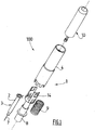
Figure 1 is an exploded perspective view of an injection set according to the invention, -
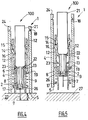
Figures 2 to 5 are simplified sectioned views of the injection set ofFigure 1 in the following respective positions: initial, insertion, end-of-injection and final protection, -
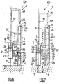
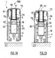
Figures 6 to 10 are sectioned views of a first alternative form of embodiment of an injection set according to the invention in the following respective positions: initial, insertion, end-of-injection before triggering of safety, triggering of safety and final protection, -
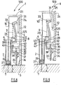
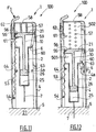
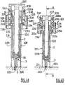
Figures 11 to 14 are sectioned views of a second alternative form of embodiment of an injection set according to the invention, in the following respective positions: initial, insertion, end-of-injection and final protection, -
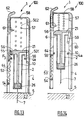
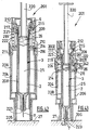
Figures 15 to 17 are sectioned views of a third alternative form of embodiment of an injection set according to the invention in the following respective positions: initial, insertion and end-of-injection, -
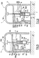
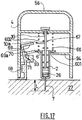
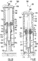
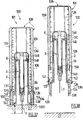
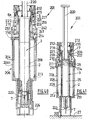
Figures 18 to 22 are sectioned views of a fourth alternative form of embodiment of an injection set according to the invention in the following respective positions: initial, pre-insertion, insertion and start-of-injection, end-of-injection and final protection, -
Figures 23 to 27 are sectioned views of a fifth alternative form of embodiment of an injection set according to the invention in the following respective positions: initial, insertion, during injection, end-of-injection and final protection, -
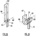
Figures 28 to 29 are partial perspective views of the assistance device ofFigures 23 to 27 , -
Figure 30 is an exploded perspective view of a sixth alternative form of embodiment of an injection set according to the invention, -
Figures 31 to 34 are sectioned views of the injection set ofFigure 30 in the following respective positions: initial, needle insertion, end-of-injection and final protection, -
Figures 35 to 38 are sectioned views of a seventh alternative form of embodiment of the injection set according to the invention depicted respectively in the following positions: initial, needle insertion, end-of-injection, and final protection, -
Figure 39 is a detailed exterior view of the means of locking the injection set ofFigures 35 to 38 in the final protection position, -
Figures 40 to 45 are side cross section views of an eigth alternative embodiment of an injection set according to the invention depicted in the following positions: before use, after deshielding and before insertion, before insertion during the deactivation of the first retaining means, insertion position, insertion position during the deactivation of the second retaining means, protection position, -
figures 46 to 49 are side cross section views of a ninth alternative embodiment of an injection set according to the invention depicted in the following positions: before use, insertion position, insertion position during the release of the locking means, insertion position during the deactivation of the second retaining means, -
figure 50 is a cross section view offigure 49 along line AA, -
figure 51 is a cross section view of the device offigure 46 in the protection position. - In order to make the invention easier to understand, the injection assistance device is described assembled with an injection device with which it forms an injection set.
-
Figure 1 depicts an injection set 100 according to the invention, comprising aninjection assistance device 1 for aninjection device 3, thisinjection device 3 comprising ahollow body 2 intended to receive aproduct 25 that is to be injected, at least onehollow injection needle 7 intended to penetrate theinjection site 27, and at least onepiston plunger 26 housed in the saidbody 2, the saidbody 2 and the saidpiston plunger 26 being able to be moved in axial translation one relative to the other as will be visible fromFigures 2 to 5 . Thebody 2 also comprises aflange 6 at its proximal end. - The
injection assistance device 1 ofFigures 1 to 5 comprises ahollow sleeve 4 which at least partially houses the saidbody 2, thissleeve 4 being provided with at least onebearing surface 5 intended to come into contact with the surface of theinjection site 27 as shown inFigures 2 to 4 . - The
injection assistance device 1 also comprises anintermediate ring 8 attached to theflange 6 of thebody 2, aspring 9, arranged between the saidsleeve 4 and the saidintermediate ring 8, and aplunger rod 10 intended to be coupled to thepiston plunger 26 in order to inject theproduct 25. - The
plunger rod 10 is equipped with ahead 21 the distal end of which is equipped with anexternal ramp 22. - At its proximal end the
intermediate ring 8 comprises at least an externalradial rim 11 from which two diametricallyopposed tabs 12 extend in the proximal direction, eachtab 12 being equipped on its internal wall and in its distal part with at least one internalradial projection 13 able to deflect radially outwards, eachtab 12 further comprising, formed in the wall of its proximal part, at least onetab 14 comprising an external radialproximal tooth 15 and an internal radialdistal tooth 16, each of the said proximal 15 and distal 16 teeth being able to deflect radially in such a way that the outwards radial flexing of the saiddistal tooth 16 causes the inwards radial flexing of the saidproximal tooth 15. - The
distal tooth 16 is equipped with an inclinedproximal face 20. The internalradial projection 13 comprises a slopingproximal face 23. - The
intermediate ring 8 further comprises at least one externalradial stop 17 formed on the external wall of its distal part. - The
sleeve 4 comprises at least onenotch 18 formed on the internal wall of its proximal part and an internalradial step 19 situated on the internal wall of its distal part. - As can be seen from
Figures 2 to 5 , the proximal end of thespring 9 bears against the distal face of the saidradial step 19 and the distal end of thespring 9 bears against the proximal face of the saidradial stop 17. - The
injection assistance device 1, into which theinjection device 3 is integrated, is supplied in the initial position shown inFigure 2 . In this position, theflange 6 of thebody 2 is clipped between the said externalradial rim 11 and the said internalradial projection 13. Thespring 9 is compressed and the saidproximal tooth 15 is engaged in the saidnotch 18 so as to block the translational movement of the saidintermediate ring 8 with respect to the saidsleeve 4. Thesleeve 4 entirely covers thehollow needle 7 and theinjection assistance device 1 is therefore completely safe. - In order to proceed with the injection, the user grasps hold of the
sleeve 4 via a proximal region for holding 24 and places it bearing, via itsbearing surface 5, against the surface of theinjection site 27. - The user then engages the
plunger rod 10 inside thesleeve 4 in the axial direction. During this movement, the saidexternal ramp 22 comes into contact with the said inclinedproximal face 20 causing the saiddistal tooth 16 to flex outwards and therefore causing the saidproximal tooth 15 to flex inwards, the saidproximal tooth 15 disengaging from the saidnotch 18 and releasing the saidintermediate ring 8 which is moved in the distal direction by the deployment of the saidspring 9. As theintermediate ring 8 is also fixed to the saidcollar 6, it carries with it the saidbody 2 and therefore the saidneedle 7 which penetrates theinjection site 27 as shown inFigure 3 . - Thus, insertion of the
needle 7 into theinjection site 27 is performed automatically, without the user having to move the saidbody 2 by hand. - As can be seen from
Figure 3 , theneedle 7 has penetrated theinjection site 27 to a predetermined insertion length L controlled by the distal end of the saidintermediate ring 8 coming into abutment against the surface of theinjection site 27 and the thrusting of the saidspring 9 in the partially expanded state against the saidradial stop 17. In this insertion position, theaxial gap 301 left between theintermediate ring 8 and thesleeve 4 allows theneedle 7 to be kept at the insertion depth L even if the user moves the hand holding thesleeve 4 slightly away from theinjection site 27. - Actually, if during the injection step, the user, for instance by inadvertence, releases the distal pressure he exerts on the
sleeve 4 when applying it on theinjection site 27, causing thereby a limited proximal movement of saidsleeve 4, then thespring 9, because it is in a partially expanded state and thanks to the presence of thegap 301, is allowed to dampen said proximal movement by expanding a little more and thereby causing theintermediate ring 8 to be urged towards thesite injection 27. Thebody 2 being coupled to saidintermediate ring 8, it is also urged towards theinjection site 27 and theneedle 7 is maintained at a constant insertion length, namely its predetermined insertion length L. - On the contrary, if during the injection step, the user increases the distal pressure he exerts on the
sleeve 4 when applying it on theinjection site 27, causing thereby a limited distal movement of saidsleeve 4, then thespring 9, because it is in a partially expanded state and thanks to the presence of thespace 302 between theradial step 19 of thesleeve 4 and theradial stop 17 of theintermediate ring 8, is allowed to dampen said distal movement by being compressed, thereby maintaining theneedle 7 at a constant insertion length, namely its predetermined insertion length L. - The influence of any increase or release of the distal pressure exerted by the user on the
sleeve 4 during injection is therefore neutralized by the presence of thespring 9 in a partially expanded state. - During the insertion step that has been described, the
plunger rod 10 was not release by the retaining means before thebody 2. In consequence, there is limited risk that the injection be started before the needle is inserted at the right insertion depth L. - In addition, in an embodiment not depicted, the
injection assistance device 1 can be arranged in order to allow sequential displacement of, in a first step thebody 2 and theplunger rod 10 relative to thesleeve 4 and in a second step of theplunger rod 10 relative to saidbody 2. To do so, internal radialdistal teeth 16 and said proximal 15 teeth and said distal 16 teeth are arranged in order to, when the user engages theplunger rod 10 inside thesleeve 4 in the axial direction, first allow the disengagement of the in two separate steps, a first step during which, proximal 15 teeth are disengaged from proximal 15 teeth fromnotch 18 to allow insertion of theneedle 7 with no relative displacement of theplunger rod 10, and a second step in which, when theintermediate ring 8 is in abutment with theinjection site 27, the distal 16 teeth are disengaged from theexternal ramp 22 of thepiston rod 10 to allow displacement of theplunger rod 10 relative to thebody 2 and allow the injection of theproduct 25 in theinjection site 27. In consequence, there is no risk that the injection be started before the needle is inserted at the right insertion depth L. - In order to actually perform the injection, the user, still keeping the
assistance device 1 pressed against theinjection site 27, grasps hold of theplunger rod 10 and couples it to the saidpiston plunger 26 so as to move the saidpiston plunger 26 in the distal direction. The saidpiston plunger 26 then drives theproduct 25 towards theneedle 7, and the injection is performed. - At the end of injection, as shown in
Figure 4 , the saidexternal ramp 22 comes into contact with the said slopingproximal face 23 and, under the effect of an axial force exerted on thehead 21 of theplunger rod 10, causes the saidradial projection 13 to flex radially outwards thus disengaging the saidflange 6 from the saidintermediate ring 8. - The user then withdraws the
injection assistance device 1 from the surface of theinjection site 27 and thespring 9, relieved of the pressure exerted on it by the said surface of the saidinjection site 27, returns to its expanded state, carrying with it the saidintermediate ring 8, of which the distal part covers theneedle 7 as shown inFigure 5 . - The said
radial stop 17 then comes into abutment against the bearingsurface 5 of the saidsleeve 4, thus locking the translational movement of the saidsleeve 4 with respect to theintermediate ring 8. - Thus, the
injection assistance device 1 is completely safe and the user can discard it without the risk of needlestick injury. - In an embodiment, not depicted, of the invention, insertion of the needle is triggered by a rotation of the said intermediate ring with respect to the said plunger rod.
-
Figures 6 to 10 illustrate a first alternative form of embodiment of the injection set 100 according to the invention. Identical references have been maintained. - The injection set 100 of
Figures 6 to 10 comprises aninjection assistance device 1 for aninjection device 3, thisinjection device 3 comprising ahollow body 2 intended to receive aproduct 25 that is to be injected, at least onehollow injection needle 7 intended to penetrate theinjection site 27, and at least onepiston plunger 26 housed in the saidbody 2. Thebody 2 also has aflange 6 at its proximal end. - The
injection assistance device 1 ofFigures 6 to 10 comprises ahollow sleeve 4 which at least partially houses the saidbody 2, thissleeve 4 being provided with at least onebearing surface 5 intended to come into contact with the surface of theinjection site 27 as shown inFigures 6 to 8 . - The
injection assistance device 1 also comprises anintermediate ring 8 attached to theflange 6 of thehollow body 2, afirst spring 9 arranged between the saidsleeve 4 and the saidintermediate ring 8, and aplunger rod 10 intended to be coupled to thepiston plunger 26 in order to perform the injection. - The
plunger rod 10 is equipped with ahead 21 forming a longitudinal skirt of which the distal end is equipped with aninternal ramp 125. - The said
intermediate ring 8 comprises adistal tooth 28, aproximal tooth 29 and at least two diametricallyopposed tabs 12 each one extending in the proximal direction from the proximal face of the saidproximal tooth 29, eachtab 12 being equipped at its proximal end with an externalradial projection 30 able to deflect radially inwards. The said externalradial projection 30 comprises an inclinedproximal face 31. The saiddistal tooth 28 also comprises an inclineddistal face 40. - In
Figures 6 to 10 , thesleeve 4 comprises a proximal part and a distal part separated from one another by an internalradial rim 32. The proximal part of the saidsleeve 4 is equipped with an internalradial stop 33 and the distal part of the saidsleeve 4 is equipped with aninternal bulge 34. - In its distal part, the said
sleeve 4 accommodates asheath 35 comprising a tubularproximal part 36 and a tubulardistal part 37, the diameter of the cross section of theproximal part 36 being smaller than the diameter of the cross section of thedistal part 37, the said proximal 36 and distal 37 parts being connected to one another by atransverse wall 38 in the form of a circular band, the saidproximal part 36 being equipped at its proximal end with an externalradial step 43 able to deflect radially inwards. The said externalradial step 43 is equipped with a slopingproximal face 39. The saidsheath 35 also comprises aslot 41 formed on the external wall of its tubulardistal part 37. - The
injection assistance device 1 ofFigures 6 to 10 also comprises asecond spring 42 arranged between the saidsheath 35 and the distal part of the saidsleeve 4. - In the initial position depicted in
Figure 6 , the saidfirst spring 9 is in the compressed state and its distal end bears against the proximal face of the saidproximal tooth 29, while its proximal end bears against the distal face of the saidradial stop 33. In this position, the saidsecond spring 42 is also in the compressed state and its distal end bears against the proximal face of the saidtransverse wall 38 of the saidsheath 35 whereas its proximal end bears against the distal face of the said internalradial rim 32. - The
intermediate ring 8 is clipped onto theflange 6 of thehollow body 2 by means of its distal 28 and proximal 29 teeth. The said externalradial projection 30 is in abutment against theproximal end 24 of the saidsleeve 4, blocking the translational movement of the saidbody 2 with respect to the saidsleeve 4. The distal face of the saidradial step 39 is in abutment against the proximal face of the saidradial rim 32, blocking the translational movement of the saidsleeve 4 with respect to the saidsheath 35. - In the initial position depicted in
Figure 6 , the saidsleeve 4 and the saidsheath 35 completely cover theneedle 7. Theinjection assistance device 1 is therefore completely safe. - In order to proceed with the administering of the
product 25, the user grasps hold of thesleeve 4 via itsproximal end 24, forming a proximal region for holding of the saidsleeve 4, and places it bearing, via itsbearing surface 5, against the surface of theinjection site 27. - The user then engages the
plunger rod 10 inside thesleeve 4 in the distal direction. During this movement, the saidinternal ramp 125 comes into contact with the said inclinedproximal face 31 causing the said externalradial projection 30 to flex and disengage from the saidsleeve 4 and release the saidintermediate ring 8, the latter being moved in the distal direction, by the deployment of the saidfirst spring 9 which returns to a partially expanded state. As theintermediate ring 8 is also fixed to the saidflange 6, it carries with it the saidhollow body 2 and therefore the saidneedle 7 which penetrates theinjection site 27 as shown inFigure 7 . - As can be seen in
Figure 7 , theneedle 7 has penetrated theinjection site 27 to a predetermined insertion length L controlled by the distal face of the saidintermediate ring 8 coming into abutment against the proximal face of the saidradial rim 32 and by the thrusting of the saidfirst spring 9 in the partially expanded state against the proximal face of theproximal tooth 29 of the saidintermediate ring 8. - In the insertion position shown on
figure 7 , agap 401 is left between thedistal tooth 28 of theintermediate ring 8 and the internalradial rim 32 of thesleeve 4. - Therefore, if during the injection step, the user, for instance by inadvertence, releases the distal pressure he exerts on the
sleeve 4 when applying it on theinjection site 27, causing thereby a limited proximal movement of saidsleeve 4, then thespring 9, because it is in a partially expanded state and thanks to the presence of thegap 401, is allowed to dampen said proximal movement by expanding a little more and thereby causing theintermediate ring 8 to be urged towards thesite injection 27. Thebody 2 being coupled to saidintermediate ring 8, it is also urged towards theinjection site 27 and theneedle 7 is maintained at a constant insertion length, namely its predetermined insertion length L. - On the contrary, if during the injection step, the user increases the distal pressure he exerts on the
sleeve 4 when applying it on theinjection site 27, causing thereby a limited distal movement of saidsleeve 4, then thespring 9, because it is in a partially expanded state and thanks to the presence of thespace 402 between theradial stop 33 of thesleeve 4 and theproximal tooth 29 of theintermediate ring 8, is allowed to dampen said distal movement by being compressed, thereby maintaining theneedle 7 at a constant insertion length, namely its predetermined insertion length L. - The influence of any increase or release of the distal pressure exerted by the user on the
sleeve 4 during injection is therefore neutralized by the presence of thespring 9 in a partially expanded state. - During the insertion step that has been described, the
intermediate ring 8 is forming a spacer that rigidly connects, during the insertion step, theplunger rod 10 to thebody 2. There is therefore no risk that the injection be started before theneedle 7 is inserted at the right insertion depth L. - In order to actually administer the
product 25, the user, still holding theinjection assistance device 1 against theinjection site 27, grasps hold of theplunger rod 10 and moves it in the distal direction. During this movement, the saidinternal ramp 125 in contact with the said inclinedproximal face 31 causes the said externalradial projection 30 to flex and disengage from the saidhead 21 of theplunger rod 10, enabling the distal displacement of the piston plunger relative to saidbody 2. The saidpiston plunger 26 then drives theproduct 25 towards theneedle 7 and the injection is administered, until thepiston plunger 26 comes in abutment with the distal end of thebody 2, as shown onfigure 8 .. - Once the injection is completed, under the effect of the axial pressure exerted on the said
intermediate ring 8 by the saidfirst spring 9, the said inclineddistal face 40 of the saiddistal tooth 28 comes into abutment against the said slopingproximal face 39 of the said externalradial step 43 and causes the inwards radial flexing of the said externalradial step 43 which disengages the saidsheath 35 from the saidsleeve 4, as shown onfigure 9 . - The user then withdraws the
injection assistance device 1 from the surface of theinjection site 27 and thesecond spring 42, relieved of the pressure exerted on it by the said surface of the saidinjection site 27 via thedistal part 37 and thetransverse wall 38 of the saidsheath 35, returns to its expanded state, carrying with it the saidsheath 35 which covers theneedle 7 as shown inFigure 10 . - As the said
second spring 42 deploys, the saidbulge 34 of the saidsleeve 4 is engaged in the saidslot 41 of the saidsheath 35, thus locking the translational movement of the saidsleeve 4 with respect to the saidsheath 35. - Thus, the
injection assistance device 1 is completely safe and the user can discard it without the risk of needlestick injury. -
Figures 11 to 29 depict a second alternative forms of embodiment of the injection set 100 according to the invention which also comprise automatic injection means. -
Figures 11 to 14 relate to a first of its alternative forms. In these figures, theinjection assistance device 1 according to the invention comprises afirst spring 53 arranged between the saidhollow body 2 and the saidsleeve 4. Thedistal end 54 of the saidfirst spring 53 is fixed to the internal wall of the distal part of the saidsleeve 4. Theproximal end 55 of the saidfirst spring 53 bears against an inclineddistal face 56 of the saidhead 21 of theplunger rod 10. - The
sleeve 4 is provided on its internal walls with aradial stop 4a. - The
injection assistance device 1 also comprises asecond spring 57 arranged between the saidhead 21 of theplunger rod 10 and the distal face of the proximal region for holding 58 of the saidsleeve 4. - The
head 21 of theplunger rod 10 comprises alongitudinal tab 59, extending in the distal direction, able to deflect outwards and engaging the saidhead 21 of theplunger rod 10 and the saidflange 6, as depicted inFigure 13 . InFigures 11 to 14 , thislongitudinal tab 59 is in the form of an articulated arm comprising a window (not depicted) able to collaborate with along bulge 60 formed on the proximal part of the internal wall of the saidsleeve 4. - In the initial position, as depicted in
Figure 11 , the saidfirst spring 53 is in the stretched-out state. It is kept in this stretched-out state by a bearingsurface 61 coupled to abutton 62 situated on the external wall of the saidsleeve 4, the saidbearing surface 61 being able to deflect outwards and to release the saidfirst spring 53 via pressure exerted on the saidbutton 62. - The said second spring 52 is in the state of rest.
- The
plunger rod 10 is separated from thebody 2 by an articulatedarm 59 which, in the insertion step, as described below, will form spacer means preventing theplunger rod 10 from moving relative to saidbody 2. - Once the user has grasped the injection set 100 by the
sleeve 4 and has brought saidsleeve 4 to bear against the surface of theinjection site 27, the user presses on thebutton 62 in the direction of the arrow F1 depicted inFigure 11 to deflect the saidbearing surface 61 and release the saidfirst spring 53 which, on returning to a compressed state, drives the saidhead 21 of theplunger rod 10 in the distal direction. As the saidhead 21 of theplunger rod 10 is rigidly connected to the saidflange 6 by the articulatedarm 59, it is the assembly comprising theplunger rod 10 and thehollow body 2, and therefore theneedle 7, which is moved in the distal direction, the said movement automatically inserting the saidneedle 7, as shown inFigure 12 . - During this movement, the said
second spring 57, the distal end of which is fixed to the proximal face of the saidhead 21 of theplunger rod 10, has been stretched out, as shown inFigure 12 , and is therefore in a partially expanded state. - At the end of the insertion position, the said articulated
arm 59 reaches thedistal end 63 of the saidbulge 60 and is deflected outwards, disengaging the saidhead 21 of theplunger rod 10 from the saidflange 6, as shown by the arrow F2 inFigure 12 . - The said
first spring 53 continues its return to its state of rest and carries with it the saidhead 21 of theplunger rod 10 which, free to move in the translational movement with respect to the saidflange 6 and therefore with respect to the saidhollow body 2, drives the saidpiston plunger 26 in the distal direction and administers theproduct 25. Thus, the injection is performed automatically without the user having to intervene. - During the injection step, the said
second spring 57 is continued to be stretched out under the action of the saidfirst spring 53. - As can be seen from
figures 12 and13 , agap 501 is left between the flange of thebody 2 and theradial stop 4a of thesleeve 4. - Therefore, if during the injection step, the user, for instance by inadvertence, releases the distal pressure he exerts on the
sleeve 4 when applying it on theinjection site 27, causing thereby a limited proximal movement of saidsleeve 4, then thespring 57, because it is in a partially expanded state and thanks to the presence of thegap 501, is allowed to dampen said proximal movement by expanding a little more and thereby causing thehead 21 of theplunger rod 10, and by consequence thebody 2, to be urged towards thesite injection 27. Theneedle 7 is therefore maintained at a constant insertion length, namely its predetermined insertion length L. - On the contrary, if during the injection step, the user increases the distal pressure he exerts on the
sleeve 4 when applying it on theinjection site 27, causing thereby a limited distal movement of saidsleeve 4, then thespring 57, because it is in a partially expanded state and thanks to the presence of thespace 502 between the distal face of the proximal region for holding 58 of thesleeve 4 and thehead 21 of the plunger rod, is allowed to dampen said distal movement by being compressed, thereby maintaining theneedle 7 at a constant insertion length, namely its predetermined insertion length L. - The influence of any increase or release of the distal pressure exerted by the user on the
sleeve 4 during injection is therefore neutralized by the presence of thespring 57 in a partially expanded state. - At the end of the injection position, as shown in
Figure 13 , theproximal end 55 of the saidfirst spring 53 disengaged from the inclineddistal face 56 of the saidhead 21 of theplunger rod 10 in the direction of the arrow F3 because this head has arrived opposite alongitudinal depression 64 formed on the distal part of the internal wall of the saidsleeve 4. The saidfirst spring 53 therefore no longer exerts any tension on the saidsecond spring 57 which returns to its compressed state of rest and carries with it the assembly comprising thehead 21 of theplunger rod 10 and thehollow body 2, returning the saidneedle 7 to the inside of the saidsleeve 4, as shown inFigure 14 . - Thus, in the final protection position as depicted in
Figure 14 , the saidneedle 7 is completely covered and the injection set 100 is safe. It can be discarded without any risk of needlestick injury to the user. -
Figures 15 to 17 depict a second alternative form of embodiment of the injection set 100 according to the invention, of which the saidsleeve 4 comprises atransverse wall 65 against the distal face of which the respective proximal ends of afirst spring 66 and of asecond spring 67 bear. The distal end of the saidfirst spring 66 bears against the proximal face of the saidflange 6. The distal end of the saidsecond spring 67 bears against the saidpiston plunger 26. - The
sleeve 4 is provided on its internal wall with aradial stop 94. - The
plunger rod 10 is provided with aradial projection 10a. - The said
injection assistance device 1 also comprises anintermediate ring 68, the proximal end of which comprises a first tab or laterallymobile tab 69 engaged in the saidflange 6 in the initial position, saidtab 69 being able to deflect in order to release the saidflange 6 and therefore the saidhollow body 2 through the collaboration of one 70 of its surfaces with a complementingsurface 71 situated on acomplementary rim 93 itself situated on the internal wall of the saidsleeve 4. Thetab 69 comprises aradial rim 69a. - In the initial position, as depicted in
Figure 15 , the said first andsecond springs first tab 69 is engaged in the saidflange 6. - The
radial rim 69a of thetab 69 is engaged in theradial projection 10a of theplunger rod 10. - The user grasps the
sleeve 4 of theinjection assistance device 1 and applies it on theinjection site 27. The user then presses on theproximal bearing region 58 to initiate the automatic insertion of theneedle 7. This initiation takes place through the saidsurface 70 of the said deflectingfirst tab 71, coming into abutment against the saidcomplementary surface 71 of the saidsleeve 4 and subsequent deflection of the saidtab 69 which releases at the same time theflange 6 and theradial projection 10a. The saidfirst spring 66 is then free to return to a partially expanded state, carrying along with it the saidflange 6 and therefore the saidhollow body 2 and causes theneedle 7 to become inserted into theinjection site 27, as shown inFigure 16 . - Through deflection of
tab 69, theradial rim 69a of saidtab 69 has been disengaged from theradial projection 10a of theplunger rod 10, freeing saidplunger rod 10. As theplunger rod 10 is not free to move before thebody 2, the risk of inadvertent injection start before reaching the insertion depth L is limited. - The injection is performed automatically thanks to
spring 67, without the user having to intervene. - As can be seen from
figures 16 and17 , agap 601 is present between theflange 6 of thebody 2 and theradial stop 94 of thesleeve 4. - Therefore, if during the injection step, the user, for instance by inadvertence, releases the distal pressure he exerts on the
sleeve 4 when applying it on theinjection site 27, causing thereby a limited proximal movement of saidsleeve 4, then thespring 66, because it is in a partially expanded state and thanks to the presence of thegap 601, is allowed to dampen said proximal movement by expanding a little more and thereby causing thebody 2, to be urged towards thesite injection 27. Theneedle 7 is therefore maintained at a constant insertion length, namely its predetermined insertion length L. - On the contrary, if during the injection step, the user increases the distal pressure he exerts on the
sleeve 4 when applying it on theinjection site 27, causing thereby a limited distal movement of saidsleeve 4, then thespring 66, because it is in a partially expanded state and thanks to the presence of thespace 602 between the distal face of thetransversal wall 65 of thesleeve 4 and thebody 2, is allowed to dampen said distal movement by being compressed, thereby maintaining theneedle 7 at a constant insertion length, namely its predetermined insertion length L. - The influence of any increase or release of the distal pressure exerted by the user on the
sleeve 4 during injection is therefore neutralized by the presence of thespring 66 in a partially expanded state. -
Figures 18 to 29 relate to two alternative forms of embodiment of the injection set 100 according to the invention, in which forms the automatic-injection means are activated when the resultant of the forces of the said first and/or second and/or third return means, the force needed to overcome the stiction of the saidpiston plunger 26 and the force with which thesleeve 4 bears against the saidinjection site 27, is directed in the distal direction. - The
injection assistance device 1 ofFigures 18 to 22 comprises asleeve tube 75 accommodating the saidsleeve 4. Theinjection assistance device 1 also comprises afirst spring 76 arranged between the saidpiston plunger 26 and the proximal face of the proximal region for holding 77 of the saidsleeve tube 75. The saidinjection assistance device 1 also comprises asecond spring 78 arranged between the saidhollow body 2 and the saidsleeve 4. - The said
first spring 76 is housed within acasing 79, thedistal end 80 of which bears, in the initial position as depicted inFigure 18 , against a deflectingtab 81 formed on the internal wall of the saidsleeve tube 75. In the initial position, the saidfirst spring 76 is in the compressed state and the saidsecond spring 78 is in the expanded state. - The user grasps the
sleeve tube 75 and applies theinjection assistance device 1 on theinjection site 27. - When the user presses against the said proximal region for holding 77 of the said
sleeve tube 75, as shown inFigure 19 , the proximal end of the saidsleeve 4 deflects the saidtab 81 and disengages the saiddistal end 80 of the saidcasing 79 and thus releases the saidfirst spring 76 which returns to a partially expanded state, carrying with it, at the same time, the saidcasing 79 and the saidbody 2 and causing the saidneedle 7 to be inserted automatically into theinjection site 27, as shown inFigure 20 . While this is happening, the saidsecond spring 78, the proximal end of which bears against the distal face of the saidflange 6, is compressed. - As the
plunger rod 10 is not free to move before thebody 2, the risk of inadvertent injection start before reaching the insertion depth L is limited. - In the end-of-insertion position, the resultant of the forces of the said first and
second springs piston plunger 26 and the force with which the saidsleeve 4 is pressed against the saidinjection site 27 is directed in the distal direction and so the saidfirst spring 76 drives the saidpiston plunger 26 into the saidhollow body 2 and administers the injection automatically, as shown inFigure 21 . - As can be seen on
figure 20 , agap 701 is present between theflange 6 of thebody 2 and aradial rim 82 formed on the internal wall of the saidsleeve tube 75. - Therefore, if during the injection step, the user, for instance by inadvertence, releases the distal pressure he exerts on the
sleeve tube 75 when applying it on theinjection site 27, causing thereby a limited proximal movement of saidsleeve tube 75, then thefirst spring 76, because it is in a partially expanded state and thanks to the presence of thegap 701, is allowed to dampen said proximal movement by expanding a little more and thereby causing thebody 2, to be urged towards thesite injection 27. Theneedle 7 is therefore maintained at a constant insertion length, namely its predetermined insertion length L. - On the contrary, if during the injection step, the user increases the distal pressure he exerts on the
sleeve tube 75 when applying it on theinjection site 27, causing thereby a limited distal movement of saidsleeve tube 75, then thefirst spring 76, because it is in a partially expanded state and thanks to the presence of thespace 702 between the distal face of the proximal region for holding 77 of thesleeve tube 75 and thepiston plunger 26, is allowed to dampen said distal movement by being compressed, thereby maintaining theneedle 7 at a constant insertion length, namely its predetermined insertion length L. - The influence of any increase or release of the distal pressure exerted by the user on the
sleeve tube 75 during injection step is therefore neutralized by the presence of thespring 76 in a partially expanded state. - At the end of injection, the user withdraws the injection set 100 from the
injection site 27 and the saidsecond spring 78, on returning to its expanded state, drives the saidsleeve 4 in the distal direction and theneedle 7 is covered up again, as shown inFigure 22 . The injection set 100 is therefore completely safe. - The
injection assistance device 1 ofFigures 23 to 29 is a fifth alternative form of embodiment of theinjection assistance device 1 ofFigures 18 to 22 in which the two springs are replaced by asingle leaf spring 83. Theinjection assistance device 1 ofFigures 23 to 29 comprises no sleeve tube. - The
fixed end 84 of the saidleaf spring 83 is fixed to the internal wall of the distal part of the saidsleeve 4. The movingend 86 of the saidleaf spring 83 is held, in the initial position, with the aid of a bearing surface coupled to abutton 94 similar to the one described inFigure 11 . - The moving
end 86 of the saidleaf spring 83 is connected to theproximal end 87 of a deformable movingcomponent 88 of which thedistal end 92 is itself linked to the saidhead 21 of theplunger rod 10 by apivot connection 89, as shown inFigures 28 and 29 . - The said moving
component 88 is housed in arail 90 within which it can move translationally, the saidrail 90 having the overall shape of a J, namely a first longitudinal part, a curved part and a second longitudinal part shorter than the said first longitudinal part. - In the initial position, as depicted in
Figure 23 , the saidleaf spring 83 is in the stretched-out state. - The user grasps the
sleeve 4 of theinjection assistance device 1 and applies it on theinjection site 27. By pressing the saidbutton 95, the saidleaf spring 83 is released and tries to return to its state of rest. As it does so, its movingend 86 pushes thecomponent 88 along therail 90, the said movingcomponent 88 driving the saidhead 21 of theplunger rod 10, the said movingcomponent 88 being in its undeformed configuration as shown inFigure 28 . The saidhead 21 of theplunger rod 10 itself drives the saidbody 2 and causes the saidneedle 7 to be inserted automatically into theinjection site 27 as shown inFigure 24 . - At the end of the insertion position, as shown in
Figure 24 , the saidleaf spring 83 continues its return to its compressed state at rest and the resultant of the forces of the saidleaf spring 83, of the force needed to overcome the stiction of the saidpiston plunger 26, and with which the saidsleeve 4 bears against the saidinjection site 27 is directed in the distal direction and so the saidspring 83 drives the saidplunger rod 10 which itself drives the saidpiston plunger 26 into the saidhollow body 2 and administers the injection automatically, as shown inFigure 25 . - As can be seen on
figures 24 and 25 , agap 801 is present between theflange 6 of thebody 2 and aradial rim 91 formed on the internal wall of thesleeve 4. - Therefore, if during the injection step, the user, for instance by inadvertence, releases the distal pressure he exerts on the
sleeve 4 when applying it on theinjection site 27, causing thereby a limited proximal movement of saidsleeve 4, then thespring 83, because it is in a partially expanded state and thanks to the presence of thegap 801, is allowed to dampen said proximal movement by expanding a little more and thereby causing thebody 2, to be urged towards thesite injection 27. Theneedle 7 is therefore maintained at a constant insertion length, namely its predetermined insertion length L. - On the contrary, if during the injection step, the user increases the distal pressure he exerts on the
sleeve 4 when applying it on theinjection site 27, causing thereby a limited distal movement of saidsleeve 4, then thespring 83, because it is in a partially expanded state and thanks to the presence of thespace 802 between the distal face of the proximal region for holding of thesleeve 4 and theflange 6 of thebody 2, is allowed to dampen said distal movement by being compressed, thereby maintaining theneedle 7 at a constant insertion length, namely its predetermined insertion length L. - The influence of any increase or release of the distal pressure exerted by the user on the
sleeve 4 during injection is therefore neutralized by the presence of thespring 83 in a partially expanded state. - As shown in
Figure 26 , the saidleaf spring 83 continues its return to its state of rest and the distal end of the said movingcomponent 88 engages in the curved part of the saidrail 90 and in so-doing pivots about thepivot connection 89 then rises back up inside the second longitudinal part of the saidrail 90 as shown inFigures 27 and29 . As the saiddistal end 92 of the said movingcomponent 88 rises back up inside the said second longitudinal part of the saidrail 90, the said movingcomponent 88, via itspivot connection 89, carries along with the saidplunger rod 10, as shown inFigure 29 . The saidhead 21 of theplunger rod 10 itself drives along the saidhollow body 2 and therefore theneedle 7 which moves up inside the saidsleeve 4, as shown inFigure 27 . The injection set 100 is therefore completely safe. - Reference is now made to
figures 30 to 34 which depict an injection set 100 according to the invention comprising aninjection assistance device 101 for aninjection device 3 comprising abody 2, aplunger rod 146, asleeve 104 and asleeve tube 106. Thesleeve tube 106 defines alongitudinal skirt 150 of which the distal part, in the insertion position as shown inFigure 32 , covers the proximal part of thesleeve 104. Thebody 2 is intended to receive theproduct 25 that is to be injected. In the example depicted, thisbody 2 is equipped at its proximal end with aflange 6. In an alternative form of the invention, not depicted, thisflange 6 could be attached to thebody 2. In these figures, thebody 2 is equipped at its distal end with ahollow injection needle 7 intended to penetrate theinjection site 27 to a predetermined insertion depth L. - In
Figure 30 , theplunger rod 146 comprises a plunger rod head which is extended in the distal direction by alongitudinal skirt 148 extending in the distal direction. Theplunger rod 146 is able to move with respect to thebody 2 and is intended to be urged by an axial pressure in the distal direction in order to perform the injection. - As is apparent from
Figures 31 to 34 , thesleeve 104 houses thebody 2 and is able to move with respect to thisbody 2 between an insertion position (Figures 32 and33 ) in which theneedle 7 is exposed and a final protection position in which thesleeve 104 entirely covers the needle 7 (seeFigure 34 ). - In
Figure 30 , theinjection assistance device 101 further comprises afirst spring 110 arranged between thebody 2 and the saidsleeve 104, and asecond spring 111 arranged between thelongitudinal skirt 148 of the saidplunger rod 146 and thesleeve tube 106. - In the example depicted, the distal end of the
longitudinal skirt 148 of the saidplunger rod 146 is equipped with an exteriorradial rim 112. Thisrim 112 may be in the form of a continuous or discontinuous annular bulge. Thesleeve 104 comprises aradial stop 113 situated on its internal wall, as can be seen inFigure 31 . Thisradial stop 113 may be in the form of a continuous or discontinuous annular bulge. Thesleeve 104 at its distal end comprises an externalradial step 114. Thisstep 114 may be in the form of a continuous or discontinuous annular bulge. The proximal end of thesleeve 104 is equipped with aninternal ramp 120. The distal end of thesleeve 104 is equipped with abearing surface 105 designed to be placed in contact with theinjection site 27. Thesleeve 104 comprises, between itsradial stop 113 and itsbearing surface 105 an intermediateradial stop 109. - Still in the example depicted in
Figures 30 to 34 , thesleeve tube 106 is equipped at its distal end with an internalradial tooth 115. Thisinternal tooth 115 may be in the form of a continuous or discontinuous annular bulge. Thesleeve tube 106 comprises a region for holding 108, on which the user exerts force in order to carry out the injection operation as will be seen later on. - The
injection assistance device 101 ofFigure 30 further comprises anintermediate ring 116 attached to theflange 6, the saidintermediate ring 116 being continued in the distal direction by atubular part 117 the distal end of which is provided with at least one externalradial projection 118. Thisradial projection 118 comprises an inclineddistal face 119. - The
body 2 contains theproduct 25 that is to be injected and is closed off, at its opposite end to theneedle 7, by apiston plunger 26 connected to theplunger rod 146. - The way in which the injection set 100 works will now be described with reference to
Figures 31 to 34 . - The injection set 100 is supplied at rest in the state depicted in
Figure 31 . In this pre-use initial position, thesleeve 104 completely covers theneedle 7. Thus, the injection set 100 is safe, any needlestick injury being avoided. - As can be seen in
Figure 31 , the distal end of thefirst spring 110 bears against the proximal face of the saidradial stop 113 and its proximal end bears against the distal face of the saidintermediate ring 116. As far as thesecond spring 111 is concerned, its distal end bears against the proximal face of theradial rim 112 and its proximal end bears against the internal wall of the region for holding 108. - In
Figure 31 , thefirst spring 110 can in the relaxed state or in a partially compressed state and thesecond spring 111 is in a partially compressed state. Thus, thesleeve 104 is retained, in terms of proximal translation with respect to thebody 2, by the respective thrusts of the first and of thesecond spring radial rim 112 bearing against the proximal face of theradial projection 118 and, on the other hand by the proximal face of theradial tooth 115 bearing against the distal face of the externalradial step 114. In addition, thesleeve 104 is retained, in terms of distal translation with respect to thebody 2, by the abutment of its intermediateradial stop 109 against the internalradial tooth 115 of thesleeve tube 106. - In order to perform the injection, the user grasps hold of the
injection assistance device 101 via thesleeve tube 106, and places the bearingsurface 105 of thesleeve 104 at right angles onto the surface of theinjection site 27, as shown inFigure 32 . - Once the
injection assistance device 101 is positioned in the desired location for the injection, the user exerts axial force in the distal direction on the region for holding 108 of thesleeve tube 106 in order to proceed with the phase of inserting theneedle 7 into theinjection site 27. - The
sleeve tube 106 which is in direct contact with theplunger rod 146 will push it in the distal direction without any absorption of the force applied by any deformable means. As the force to overcome the stiction of thepiston plunger 26 of theplunger rod 146 is greater than the force of compression of thefirst spring 110 combined with the force to overcome the friction of the penetration of theneedle 7 in theinjection site 27, thebody 2 andplunger rod 146 assembly moves in the proximal direction under the action of the axial force, without thepiston plunger 26 being moved within thebody 2, as shown inFigure 32 . This movement causes thefirst spring 110 to become compressed. Theneedle 7 penetrates theinjection site 27 until the inclineddistal face 119 comes into abutment against theinternal ramp 120. - Thus, the
needle 7 has penetrated theinjection site 27 to a perfectly defined insertion depth L as can be seen inFigure 32 . By virtue of the inclineddistal face 119 coming into abutment against theinternal ramp 120, it is then no longer possible to cause theneedle 7 to penetrate any further into theinjection site 27. The insertion depth L is thus perfectly controlled. The insertion depth L can be adjusted by using anintermediate ring 116 of a predetermined specific thickness. - Moreover, during this insertion step, the coupling means, that is to say the
plunger rod 146, are mechanically rigid between thesleeve tube 6 and thebody 2. In this insertion step, there is therefore no way to start moving distally theplunger rod 146 related to thebarrel 2, therefore, no risk to start the injection before reaching the right insertion depth. Theinjection assistance device 101 offigures 30 to 34 therefore ensures a two step use, with a first step for the insertion, and a second step for the injection. - Under the effect of an additional axial force on the region for holding 108 of the
sleeve tube 106, theinternal ramp 120 of the proximal end of thesleeve 140 presses against the inclineddistal face 119 of theprojection 118 and causes thethird projection 118 to flex inwards, thus disengaging theprojection 118 from therim 112. This disengagement releases thesecond spring 111 which, in returning to its relaxed state, drives theplunger rod 146 in the distal direction, the saidplunger rod 146 then automatically administering the injection by driving thepiston plunger 26 which, in turn, expels theproduct 25 towards theneedle 7, as shown inFigure 33 . - The device of
figures 30 to 34 therefore ensures a two step use, with a first step for the insertion, and a second step for the injection. - In an embodiment, not depicted, of the invention, the
second spring 111 is kept in the compressed state by a button situated on the exterior wall of thesleeve tube 106, the said button being able to deflect and to release thesecond spring 111 under the effect of pressure by the user on the said button. - At the end of injection, as shown in
Figure 33 , the injection depth of theneedle 7 has not varied, thepiston plunger 26 is at the end of its travel in thebody 2 and thefirst spring 110 is still in the compressed state. - As can be seen on
figures 32 and33 , agap 901 is present between the internalradial tooth 115 of thesleeve tube 106 and the intermediate radial stop of thesleeve 104. - During the injection step, the
second spring 111 is a partially expanded state. Therefore, if during the injection step, the user, for instance by inadvertence, releases the distal pressure he exerts on thesleeve tube 106 when applying it on theinjection site 27, causing thereby a limited proximal movement of saidsleeve tube 106, then thespring 111, because it is in a partially expanded state and thanks to the presence of thegap 901, is allowed to dampen said proximal movement by expanding a little more and thereby causing thelongitudinal skirt 148 of theplunger rod 146, and therefore thebody 2, to be urged towards thesite injection 27. Theneedle 7 is therefore maintained at a constant insertion length, namely its predetermined insertion length L. - To finish off the operation and make the
injection assistance device 101 safe, the user then releases the force on the region for holding 108 of thesleeve tube 106 and withdraws theinjection assistance device 101 from theinjection site 27. As the pressure previously applied on thefirst spring 110 is suppressed, thefirst spring 110 automatically expands to return to its initial relaxed state as depicted inFigure 34 , thereby causing the deployment of thesleeve 104, which covers theneedle 7. In this final protection position, thesleeve 104 is pressed against thesleeve tube 106 with the intermediateradial stop 109 of thesleeve 104 abutting against the internalradial tooth 115 of thesleeve tube 106. - During the deployment of the
sleeve 104, a raised inclined plane (not depicted) situated on the wall of thelongitudinal skirt 150 of the saidsleeve tube 106 has collaborated with an inclined cam (not depicted) of thesleeve 104 to cause thesleeve 104 to turn with respect to the saidsleeve tube 106, and the bringing of the said inclined plane into engagement in the said inclined cam prevents any translational movement of the saidsleeve 104 with respect to the saidsleeve tube 106. - Thus, in the final protection state depicted in
Figure 34 , the injection set 100 is perfectly safe and can be discarded by the user without the risk of needlestick injury. - Another embodiment of the invention will now be described with reference to
Figures 35 to 39 . - References identical to
Figures 30 to 34 have been maintained. The injection set 100 ofFigure 35 comprises ahollow body 2, aplunger rod 146, asleeve 104 and asleeve tube 106. Thesleeve tube 106 defines alongitudinal skirt 150 of which the distal part, in the insertion position as depicted inFigure 36 , covers the proximal part of thesleeve 104. The injection set 100 also comprises an intermediatetubular component 136 and aspring 139. - The head of the
plunger rod 146 is extended in the distal direction by alongitudinal skirt 148 the distal end of which is equipped with an externalradial rim 112. Thesleeve 104 comprises, formed in its wall, at least onelongitudinal tab 127 extending in the proximal direction and able to deflect tangentially, the saidtab 127 being equipped at its proximal end with an externalradial peg 128, as shown inFigure 39 . - The
sleeve tube 106 is in the form of two concentric cylindrical sheaths, aninternal sheath 129 and anexternal sheath 130, joined together at their proximal ends by a transverse wall in the form of a circular band, this transverse wall together with theexternal sheath 130 constituting the region for holding 108 of thesleeve tube 106. Theinternal sheath 129 is attached to theflange 6 and housed inside thelongitudinal skirt 148 of theplunger rod 146. At its distal end it comprises an externalradial tooth 142, the utility of which will be explained later on. - The
external sheath 130 houses thesleeve 104 and comprises, in its distal part, aninclined cam 132 formed on the wall of the saidexternal sheath 130, the saidcam 132 comprising adistal end 133 and aproximal end 134 and is able to collaborate with thepeg 128 of the saidtab 127, as shown inFigure 39 . - The
external sheath 130 further comprises, situated on its internal wall and proximally with respect to thecam 132, aradial projection 135. Theradial projection 135 comprises an inclineddistal face 140, the utility of which will be explained later on. - The intermediate
tubular component 136 is arranged between thelongitudinal skirt 148 of the saidplunger rod 146 and theexternal sheath 130, the said intermediatetubular component 136 comprising at its proximal end an internalradial step 137, the saidtubular component 136 further comprising anotch 138 formed on its external wall. - The
spring 139 is arranged between thelongitudinal skirt 148 of the saidplunger rod 146 and theexternal sheath 130. The distal end of the saidspring 139 bearing against the proximal face of the internalradial step 137, the proximal end of the saidspring 139 bearing against the distal face of the said transverse wall of the region for holding 108 in the form of a circular band. - The
injection assistance device 101 is supplied in the state depicted inFigure 35 . In this initial position, thespring 139 is in the compressed state and with the saidradial projection 135 engaged in the saidnotch 138, the retaining means are formed of the thrust of the saidspring 139 and the saidradial step 137 coming to bear against the saidradial rim 112 on the one hand, and the saidpeg 128 coming to bear against thedistal end 133 of the saidcam 132, on the other. - In order to proceed with the insertion and injection operations, the user grasps hold of the
injection assistance device 101 via thesleeve tube 106 and places the bearingsurface 105 of thesleeve 104 at right angles onto the surface of theinjection site 27, as shown inFigure 35 . - Once the
injection assistance device 101 is positioned at the desired location for the insertion, the user exerts an axial force in the distal direction on the region for holding 108 of thesleeve tube 106 in order to proceed with the phase of inserting theneedle 7 into theinjection site 27. - The
sleeve tube 106 which is in direct contact with theplunger rod 146 will push it in the distal direction without any absorption of the force applied by any deformable means. - As the force needed to overcome the stiction of the
piston plunger 26 of theplunger rod 146 is greater than the force of compression of thespring 139 combined with the force to overcome the friction of the penetration of theneedle 7 into theinjection site 27, thebody 2,plunger rod 146 andsleeve tube 106 assembly moves in the proximal direction under the action of the axial force, without thepiston plunger 26 moving within thebody 2, as shown inFigure 36 . Theneedle 7 penetrates theinjection site 27 until on the one hand the said inclineddistal face 140 comes into abutment against the saidexternal ramp 141 and, on the other hand, the saidpeg 128 comes into abutment against theproximal end 134 of the saidcam 132, the saidtab 127 being in the unflexed state. - Thus the
needle 7 has penetrated theinjection site 27 to a perfectly defined insertion depth L as can be seen fromFigure 36 . It is then no longer possible to cause theneedle 7 to penetrate any further into theinjection site 27. The insertion depth L is thus perfectly controlled. In this example, the insertion depth L is directly linked with the dimension between theinternal sheath 129 holding theflange 6 and thebearing surface 105 and/or of the intermediatetubular component 136, thecam 132. In an embodiment not depicted, the size of thesleeve tube 106 can be adjustable to allow adjustment of the insertion depth L. - Moreover, during this insertion step, the coupling means, that is to say the
plunger rod 146, are mechanically rigid between thesleeve tube 6 and thebody 2. In this insertion step, there is therefore no way to start moving distally theplunger rod 146 related to thebarrel 2, therefore, no risk to start the injection before reaching the right insertion step. Theinjection assistance device 101 offigures 35 to 39 therefore ensures a two step use, with a first step for the insertion, and a second step for the injection. - Under the effect of an additional axial force on the region for holding 108 of the
sleeve tube 106, theexternal ramp 141 pushes the inclineddistal face 140, theprojection 135 unflexes radially outwards and disengages from thenotch 138, releasing thespring 139 which deploys and carries with it the intermediatetubular component 136 and therefore theplunger rod 146 which then administers the injection by driving thepiston plunger 26. Thepiston plunger 26 expels theproduct 25 towards theneedle 7 as shown inFigure 37 . The injection is therefore administered automatically without additional manual intervention on the part of the user. - At the end of injection, as shown in
Figure 37 , thepiston plunger 26 is at the end of its travel in the closed end of thebody 2 and the depth of insertion of theneedle 7 has not varied. - In the insertion and injection positions the
spring 139 is in a partially expanded state. - As can be seen from
figures 36 and37 , agap 1001 is present between the intermediatetubular component 136 and thesleeve tube 106. - Therefore, if during the injection step, the user, for instance by inadvertence, releases the distal pressure he exerts on the
sleeve tube 106 when applying it on theinjection site 27, causing thereby a limited proximal movement of saidsleeve tube 106, then thespring 139, because it is in a partially expanded state and thanks to the presence of thegap 1001, is allowed to dampen said proximal movement by expanding a little more and thereby causing the intermediatetubular component 136, and therefore thebody 2, to be urged towards thesite injection 27. Theneedle 7 is therefore maintained at a constant insertion length, namely its predetermined insertion length L. - To finish off the operation and make the injection set 100 safe, the user then releases the force on the region for holding 108 of the
sleeve tube 106 and withdraws the injection set 100 from theinjection site 27. Thetab 127 is then no longer subjected to any pressure and returns to its unflexed state by elastic return, driving thesleeve 104 with it. Likewise, thespring 139 continues to deploy in order to reach its relaxed state, driving with it the said intermediatetubular component 136, theradial step 137 of the said intermediatetubular component 136 being able to unflex radially outwards under the action of the saidspring 139 to disengage from the saidradial rim 112 of the saidplunger rod 146. - At the end of deployment of the
spring 139, the proximal face of theradial step 137 of the intermediatetubular component 136 comes into abutment against the distal face of the externalradial tooth 142 of theinternal sheath 129 and the saidintermediate component 136 is blocked in terms of translation with respect to thebody 2. - Thus, in the final protection position depicted in
Figure 38 , the injection assisteddevice 100 is completely safe and can be discarded by the user without the risk of needlestick injury. - In other forms of embodiment, not depicted, the helical springs may be replaced by leaf springs, pieces of elastomer, sealed gas chambers inside which the gas can be pressurized and expanded in succession, or any other equivalent means.
- In reference to
figures 40 to 45 , is represented aninjection assistance device 201 according to the invention, intended to be used with aninjection device 3 for administering via injection aproduct 25 into aninjection site 27. Theinjection device 3 comprises ahollow body 2 for receiving theproduct 25 to be injected. Thebody 2 is provided at itstip 223 with aninjection needle 7 intended to penetrate theinjection site 27 as shown onfigure 43 . - A
piston plunger 26, as shown onfigure 2 , is housed in thebody 2, saidpiston plunger 26 being able to be moved, by aplunger rod 220, in the example shown, in axial translation with respect to saidbody 2, in order to push saidproduct 25 towards the distal end of saidbody 2 and therefore realize injection, as shown onfigures 43 and44 . - The
injection assistance device 201 offigures 40 to 45 comprises grasping means, under the form of anouter sleeve 206 in the example shown, which receives thebody 2. In the example shown onfigures 40 to 45 , theouter sleeve 206 is made of two parts, a proximal part 206a and adistal part 206b but alternatively saidouter sleeve 206 could be one single integral part.Said body 2 is axially movable relative to saidouter sleeve 206 from an initial position, in which theneedle 7 is not exposed over the totality of its length, as shown onfigures 40-42 , to an insertion position, distally spaced relative to said initial position, in which saidneedle 7 is exposed by a predetermined insertion length L, as shown onfigure 43 . - The
outer sleeve 206 comprises, more or less in its middle region on the example shown, a portion oflarger diameter 210 defining aninner recess 211, first angled abuttingsurfaces 241 and second angled abuttingsurfaces 242. Saidouter sleeve 206 further comprises at least twoflexible projections 212 defined on the inner wall of its proximal end. - The
injection assistance device 201 offigures 40 to 45 further comprises an actuating means, represented by anintermediate sleeve 204 in the example shown. Saidintermediate sleeve 204 is received within saidouter sleeve 206 and comprises abearing surface 205 at its distal end, saidbearing surface 205 being intended to bear on theinjection site 27 as shown onfigure 42 . Saidintermediate sleeve 204 is able to move relative to saidouter sleeve 206 from a rest position, shown onfigure 41 to a bearing position, as shown onfigure 42 . - The
intermediate sleeve 204 is provided at its distal end with at least twoflexible legs 213 and at its proximal end with at least two otherflexible legs 216, which, in the initial position, bear on the inner wall of saidouter sleeve 206 and, in the rest position, cooperate with said first angled abuttingsurfaces 241. The function of these legs will be explained hereinbelow. - The
injection assistance device 201 offigures 40 to 45 further comprises aninner sleeve 208 received within saidintermediate sleeve 204. Saidinner sleeve 208 is able to move axially relative to saidbody 2 from an injection position, in which theneedle 7 is exposed, as shown onfigure 43 , to a protection position, in which saidinner sleeve 208 covers saidneedle 7, as shown onfigure 45 . - In the insertion and injection positions shown on
figures 40 to 44 , saidinner sleeve 208 is coupled to saidbody 2 by means of aring 217 in which aproximal flange 6 of saidbody 2 is clipped. Thering 217 comprises, at its distal end, at least twoflexible teeth 219 which are engaged in at least twocorresponding stops 221 formed at the proximal end of saidinner sleeve 208, from the initial position to the insertion position, as shown onfigures 40 to 43 . In the initial position as shown onfigure 40 , saidflexible teeth 219 bear radially on an innerlongitudinal wall 222 formed on theouter sleeve 206. In the rest positionflexible teeth 219 are designed to cooperate with said second angled abuttingsurfaces 242 as explained hereinbelow. - The
inner sleeve 208 comprises aradial rim 214 formed on its outer surface. As shown onfigure 40 , anhelicoïdal spring 209 is placed between theouter sleeve 206 and the inner sleeve 208 : in the initial position, as shown onfigure 40 , saidspring 209 is under tension, its proximal end bearing on aradial stop 215 formed on the inner wall of the proximal region of saidouter sleeve 206 and its distal end bearing on saidradial rim 214 of theinner sleeve 208. - The injection operation will now be explained in reference to
figures 40 to 45 . - The user is provided with the
assistance injection device 201 of the invention as shown onfigure 40 . In this position, theneedle 7 is preferably covered by aprotection cap 224 that the user removes before use. In this initial position, thebody 2 is clipped in thering 217 via itsflange 6, saidring 217 being engaged with theinner sleeve 208 by engagement of itsflexible teeth 219 in saidstops 221 of theinner sleeve 208. - The
body 2 is therefore maintained in its initial position by engagement of saidradial rim 214 of theinner sleeve 208 with theflexible legs 216 of saidintermediate sleeve 204, under the action of saidhelicoïdal spring 209 which is under tension, saidflexible legs 216 bearing radially on the inner wall of saidouter sleeve 206. - Once the user has removed the
protection cap 224, he can purge theinjection device 3 by holding theinjection assistance device 201 and pushing distally on theplunger rod 220. Once the purge is done, the user can carry on the distal movement of theplunger rod 220 to adjust the dose to be injected by expelling theproduct 25 in excess. - In order to perfom the injection, the user grasps the
injection assistance device 201 via theouter sleeve 206 and he applies saidinjection assistance device 201 on theinjection site 27 via thebearing surface 205 of saidintermediate sleeve 204, as shown onfigure 41 . In this position, theneedle 7 is covered by saidintermediate sleeve 204. - As shown on
figure 42 , the user further exerts a distal force on saidouter sieve 206, causing theintermediate sleeve 204 to move proximally relative to saidouter sleeve 206, from a rest position, shown onfigure 41 , to a bearing position, shown onfigure 42 . This movement causes the distal translation of therecess 211 relative to saidintermediate sleeve 204 and theflexible legs 216 are then deformed radially in the outward direction by said angled abuttingsurfaces 241, thereby freeing theradial rim 214, as shown onfigure 42 . Theradial rim 214 is pushed distally by thespring 209, which tends to come back to its rest position, drawing altogether theinner sleeve 208, thering 217 and thebody 2, until thetip 223 of saidbody 2 enters in contact with theinjection site 27, realizing the insertion of theneedle 7 as shown onfigure 43 . In this insertion position, theneedle 7 is inserted in theinjection site 27 on a predetermined length L and the insertion depth is directly linked with the length of theneedle 7. - In another embodiment not shown of the invention, the
intermediate sleeve 204 is provided with internal abutments designed to stop theinner sleeve 208 in the insertion position before contact of thetip 223 with theinjection site 27. In this case, the insertion depth L is not directly linked with theneedle 7 length. - In another second embodiment not shown of the invention, during the injection, the extremity of the
inner sleeve 208 is in contact with theinjection site 27, allowing a gap between theinjection site 27 and thetip 223. In this case, the insertion depth L depends on the difference between this gap and theneedle 7 length. - According to
figure 42 , during the distal movement of theinner sleeve 208, thering 217 and thebody 2, theflexible projections 212 have allowed the passage in the distal direction of thering 217. As shown onfigure 43 , the return of thering 217 and by consequence of thebody 2 in the proximal direction is now hindered by the distal surfaces of the flexible projections 212 : this allows the user to complete a vein test, that is to say to check whether theneedle 7 is in contact with a vein or not, by withdrawing theplunger rod 220 to determine whether some blood is drawn or not, without having to remove theneedle 7 from theinjection site 27. - The automatic insertion of the
needle 7 according to the invention allows a reproductible length of insertion. The handling of theinjection assistance device 201 is very simple for the user who does not have to check manually the insertion length. - As can be seen from
figure 43 , agap 2001 is pressent between thering 217 and the second angled abuttingsurfaces 242. Moreover, thespring 209 is in a partially expanded state. - Once the
needle 7 is inserted, the combination of thegap 2001 between thering 217 and the second angled abuting surfaces 242 plus the remaining possible extension of thespring 209 prevent the needle insertion length L modification, if the user inadvertantly slightly removes the pressure on theouter sleeve 206. This enables to ensure the injection of theproduct 25 at the right depth. - On the contrary, if during the injection step, the user increases the distal pressure he exerts on the
sleeve 206 when applying it on theinjection site 27, causing thereby a limited distal movement of saidouter sleeve 206, then thespring 209, because it is in a partially expanded state and thanks to the presence of thespace 2002 between theradial stop 215 of theouter sleeve 206 and theradial rim 214 of theinner sleeve 208, coupled to thebody 2, is allowed to dampen said distal movement by being compressed, thereby maintaining theneedle 7 at a constant insertion length, namely its predetermined insertion length L. - The influence of any increase or release of the distal pressure exerted by the user on the
outer sleeve 206 during injection is therefore neutralized by the presence of thespring 209 in a partially expanded state. - After the
needle 7 is inserted, the user proceeds manually with the injection of theproduct 25 by pushing distally on theplunger rod 20. - According to the
injection assistance device 201 shown onfigures 40 to 45 ,in order to adjust the dose ofproduct 25 to be injected, the user may decide to stop the injection at any time without taking any risk of accidental needlestick injury when he removes theinjection assistance device 201 from theinjection site 27. - Indeed, when the user has decided that
enough product 25 is injected, or at the end of injection, as shown onfigure 44 , the user removes theinjection assistance device 201 from the site ofinjection 27. By this action, thetip 223 of saidbody 2 is no longer retained by theinjection site 27. Thebody 2, which is coupled to thering 217 and to theinner sleeve 208 is therefore drawn distally under the action of thespring 209, which tends to come back to its rest position. During this distal translation, theflexible teeth 219 move distally with respect to said innerlongitudinal wall 222 of saidouter sleeve 206, until they contact the second angled abuttingsurfaces 242. Then, theflexible teeth 219 are deformed radially in the outward direction by the second angled abuttingsurfaces 242, as shown onfigure 44 , and they free saidstops 221 in which they were previously engaged. - The
inner sleeve 208 is therefore released from saidring 217 and saidbody 2, and is drawn distally by saidspring 209, which tends to come back to its rest position, until saidinner sleeve 208 covers theneedle 7, thereby realizing the protection of saidneedle 7, as shown onfigure 45 . - In the protection position, as shown on
figure 45 , theinner sleeve 208 is prevented from returning back in the proximal direction by means offlexible legs 213 of theintermediate sleeve 204 which are engaged with saidradial rim 214, theintermediate sleeve 204 abutting againts the proximal part of theouter sleeve 206. - The
injection assistance device 201 is therefore perfectly safe for the user and risks of accidental needlestick injuries are prevented. - In reference to
figures 46 to 51 , is represented another variant of aninjection assistance device 201 according to the invention. The references designating the same elements as infigures 40 to 45 have been maintained. Theinjection assistance device 201 offigures 46-51 is intended to be used with aninjection device 3 for injecting aproduct 25 into aninjection site 27. Theinjection device 3 comprises ahollow body 2 for receiving theproduct 25 to be injected. Thebody 2 is provided at itstip 223 with aninjection needle 7 intended to penetrate theinjection site 27 as shown onfigure 47 . - A
piston plunger 26 is housed in thebody 2, saidpiston plunger 26 being able to be moved, by aplunger rod 220, in the example shown, in axial translation with respect to saidbody 2, in order to push saidproduct 25 towards thetip 23 of saidbody 2 and therefore realize injection, as shown onfigures 47 and48 . - The
injection assistance device 201 offigures 46 to 512 comprises anouter sleeve 228 which partially receives thebody 2.Said body 2 is axially movable relative to saidouter sleeve 228 from an initial position, in which theneedle 7 is not exposed, as shown onfigure 7 , to an insertion position, distally spaced relative to said initial position, in which saidneedle 7 is exposed by a predetermined insertion length L, as shown onfigures 47 and48 . - The
outer sleeve 228 is formed of a single piece having aproximal region 228a and adistal region 228b. The distal end of saidproximal region 228a is provided with at least twoflexible legs 229 and the proximal end of saidproximal region 228a is provided with at least twoflexible teeth 230 shown onfigure 50 . - The
injection assistance device 201 offigures 46 to 51 further comprises aninner sleeve 231, having aproximal region 231a and adistal region 231b of lesser diameter than saidproximal region 231a, saidproximal region 231a being connected to saiddistal region 231b by a radial wall 231c. Saidproximal region 231a is received partially within saidouter sleeve 228 and comprises, at its proximal end, twoproximal projections 232. Saidinner sleeve 231 comprises abearing surface 205 at the distal end of itsdistal region 231b, saidbearing surface 205 being intended to bear on theinjection site 27 as shown onfigures 47 and48 . - Said
inner sleeve 231 is able to move relative to saidouter sleeve 228 from a rest position, shown onfigure 46 to a bearing position, as shown onfigure 47 . - The
inner sleeve 231 is able to move axially relative to saidbody 2 from an injection position, in which theneedle 7 is exposed, as shown onfigures 47 to 50 , to a protection position, in which saidinner sleeve 231 covers saidneedle 7, as shown onfigure 51 . - The
injection assistance device 201 offigures 46 to 51 further comprises a ring 233 receiving partially the proximal region of saidbody 2, said ring 233 being coupled to saidbody 2 by means of two prongs (not shown) that clip aproximal flange 6 of saidbody 2. - Said ring 233 is provided with a
flexible skirt 234 extending in the distal direction and able to be deformed radially, saidflexible skirt 234 comprising at its distal end a outerradial rim 235. - Said ring 233 is prolongated toward the distal direction and surrounds the
body 2. - The
injection assistance device 201 offigures 45 to 51 further comprises anannular rim 236 which is coupled to said ring 233 at least from the initial position to the insertion position by contact on theradial rim 235. - The
injection assistance device 201 offigures 46 to 51 also comprises aplunger rod 220, the distal end of which is screwed to saidpiston plunger 26. Theplunger rod 220 is intended to be manually pushed in the distal direction to cause the axial translation of saidpiston plunger 26 in saidbody 2 in the distal direction in order to realize injection. - Said
plunger rod 220 comprises at its proximal end ahead 237 provided with adistal skirt 238 extending longitudinally in the distal direction, the proximal end of saidhead 237 being provided with anouter bevel 239. - The
injection assistance device 201 offigures 46 to 51 also comprises agasket 240 which is coupled to saidplunger rod 220 from the end of injection position to the protection position, as shown onfigures 50 and 51 . - An
helicoidal spring 209 is placed between theouter sleeve 228 and the ring 233 : in the initial position, as shown onfigure 46 , saidspring 209 is under tension, its proximal end bearing on the distal surface of saidgasket 240 and its distal end bearing on the proximal surface of saidannular rim 236. - The injection operation will now be explained in reference to
figures 46 to 51 . - The
injection assistance device 201 of the invention is provided to the user in its initial position shown onfigure 46 . In this initial position, thebody 2 is clipped in the ring 233 via itsflange 6.Said body 2 is therefore maintained in its initial position by the fact that said ring 233 is engaged with theouter sleeve 228 by cooperation of saidflexible skirt 234, saidannular rim 236, saidflexible leg 229 and saidhelicoïdal spring 209. - As appears from
figure 46 , in the initial position, theneedle 7 is covered by saidinner sleeve 231, in particular by saiddistal region 231b of saidinner sleeve 231. - The user grasps the
injection assistance device 201 by theouter sleeve 228, for example by itsdistal region 228b, and he applies saidinjection assistance device 201 on theinjection site 27 via thebearing surface 205 of saidinner sleeve 231. - As shown on
figure 47 , the user further exerts a distal force on saidouter sleve 228, causing theinner sleeve 231 to move proximally relative to saidouter sleeve 228, from a rest position, shown onfigure 46 , to a bearing position, shown onfigure 47 . This movement causes the distal translation of theflexible legs 229 which come in contact with saidproximal projections 232 of saidinner sleeve 231. Theflexible legs 229 are therefore caused to deform radially in the outward direction, as shown onfigure 47 , thereby freeing theannular rim 236. Theannular rim 236 is pushed distally by thespring 209, which tends to come back to its rest position, drawing with him the ring 233 and thebody 2, until thetip 223 of saidbody 2 enters in contact with theinjection site 27, realizing the insertion of theneedle 7 as shown onfigure 47 . In this insertion position, theneedle 7 is inserted in the patient on a predetermined insertion length L. - In another embodiment of the invention not shown, the
inner sleeve 231 is provided with internal abutments designed to stop the ring 233 in the insertion position before contact of thetip 223 with theinjection site 27. In this case, the insertion depth L is not directly linked with the length of theneedle 7. - In another second embodiment not shown of the invention, during the injection, the extremity of the
inner sleeve 208 is in contact with theinjection site 27, allowing a gap between theinjection site 27 and thetip 223. In this case, the insertion depth L depends on the difference between this gap and theneedle 7 length. - As seen before, the automatic insertion of the
needle 7 according to the invention allows a reproductible length of insertion. The handling of theinjection assistance device 201 is very simple for the user who does not have to check manually the insertion length. - Once the
needle 7 is inserted, the combination of thegap 2001 between theouter sleeve 228 and theinner sleeve 231 plus the remaining possible extension of thespring 209 prevent the needle insertion length L modification, if the user inadvertantly slightly removes the pressure on theouter sleeve 228. This enables to ensure the injection of theproduct 25 at the right depth. - On the contrary, if during the injection step, the user increases the distal pressure he exerts on the
outer sleeve 228 when applying it on theinjection site 27, causing thereby a limited distal movement of saidouter sleeve 228, then thespring 209, because it is in a partially expanded state and thanks to the presence of thespace 2002 between theflexible legs 229 and theinner sleeve 231, is allowed to dampen said distal movement by being compressed, thereby maintaining theneedle 7 at a constant insertion length, namely its predetermined insertion length L. - The influence of any increase or release of the distal pressure exerted by the user on the
outer sleeve 228 during injection is therefore neutralized by the presence of thespring 209 in a partially expanded state. - Once the
needle 7 is inserted, the user proceeds manually with the injection of theproduct 25 by pushing distally on theplunger rod 220. As appears fromfigure 47 , theflexible skirt 234 of the ring 233 is engaged with saidannular rim 236 during the totality of the injection operation : in this way, even if the user decides to remove theinjection assistance device 201 from theinjection site 27 before the end of injection, that is to say before saidpiston plunger 26 has finished its course at the distal end of saidbody 2, then, theinner sleeve 231 remains in its injection position and does not cover theneedle 7, thus allowing the user to carry on the injection if desired. - At the end of injection, as shown on
figure 48 , when thepiston plunger 26 comes in contact with the distal end of saidbody 2, the distal force exerted by the user on theplunger rod 220 causes thedistal skirt 238 to come into contact with saidflexible skirt 234 of said ring 233 and to deform radially in the inward direction saidflexible skirt 234, thereby freeing saidannular rim 236. - The
annular rim 236 is pushed distally by thespring 209, which tends to come back to its rest position, until it is stopped by the proximal surface of theradial wall 231c connecting saidproximal region 231a to saiddistal region 231b of saidinner sleeve 231. - The user then maintains the
outer sleeve 228 while continuing to apply a distal force on saidplunger rod 220 as shown onfigures 49 and50 . By this action, thebevels 239 of saidplunger rod 220 come into contact with theflexible teeth 230 formed at the proximal end of saidouter sleeve 228 and cause the radial deformation of said teeth in the outward direction, thereby freeing saidgasket 240. - The user then removes the
injection assistance device 201 from theinjection site 27, as shown onfigure 51 . Saidspring 209 then tends to come back to its rest position and pushes proximally on saidgasket 240.Said gasket 240 pushes proximally on thehead 237 of saidplunger rod 220 which therefore draws saidbody 2 in the proximal direction, until saidneedle 7 is completely withdrawn within saidinner sleeve 231 as shown onfigure 51 . - The injection sets and the injection assistance devices according to the invention are particularly simple to use and are perfectly safe. The entire injection operation can easily be performed by a single unidirectional axial movement, with just one hand. Moreover, the device of the invention ensures a two step use, with a first step for the insertion, and a second step for the injection. There is therefore no way to start the injection before reaching the right insertion step. The devices ensure a predetermined stable insertion depth during the injection step even despites slight movement of the user hand.
- In addition, the injection sets and the injection assistance devices according to the invention enable the user to adjust the dose to be injected before proceeding with any injection step and/or to perform a vein test to prevent injection in the vein.
Claims (18)
- Injection assistance device (1; 101; 201) comprising an injection device (3) for injecting a product (25) into an injection site (27), this injection device (3) comprising at least one hollow body (2) intended to receive a product (25) that is to be injected, at least one hollow injection needle (7) intended to penetrate the injection site (27), and at least one piston plunger (26) housed in the said body (2), the said body (2) and the said piston plunger (26) being able to be moved in axial translation one with respect to the other,
characterized in that the said injection assistance device (1; 101; 201) comprises at least:- grasping means (4; 75; 106; 206; 228) intended to be manually handled by the user in order to apply said injection device on said injection site (27) during an insertion and an injection steps, said grasping means receiving at least in part the said body (2) and being arranged in such a way as to allow the said body (2) axial mobility between at least a first position known as the initial position in which the said needle (7) is not exposed over its insertion length, and a second position known as the insertion position in which the said needle (7) is exposed by a predetermined insertion length L,- at least first elastic return means (9; 57; 66; 76; 83; 111; 139; 209) coupled to said body (2) and to said grasping means (4; 75; 106; 206; 228), said first elastic return means (9; 57; 66; 76; 83; 111; 139; 209) being in a partially expanded state when said body (2) is in the insertion position, so as to dampen limited movement of said grasping means (4; 75; 106; 206; 228), in at least one of the two directions, respectively distal or proximal, during said injection step, said injection device being arranged in such a way that, in the insertion position, said grasping means (4; 75; 106; 206; 228) are separated from said body (2), or from an element (8; 104; 136) coupled to said body (2) at least in said insertion position, by a gap (301; 401; 501; 601; 701; 801; 901; 1001; 2001) that allows the said grasping means (4; 75; 106; 206; 228) to move with respect to said body (2) or to said element (8; 104; 136), to maintain said body (2) in the insertion position and said needle (7) at the predetermined insertion length L during the injection step, when the user increases a distal pressure on the grasping means (4; 75; 106; 206; 228) or when the user releases a distal pressure on the grasping means (4; 75; 106; 206; 228). - Injection assistance device (1; 201) according to claim 1, characterized in that said first elastic return means (9; 57; 66, 76; 83; 209) is arranged so as to dampen any limited distal or proximal movement of said grasping means (4; 75; 206; 228) during said injection step, and to maintain said body (2) in its insertion position and said needle (7) at a constant insertion length, namely said predetermined insertion length L, during the injection step, regardless of any increase or release of distal pressure exerted by the user on the grasping means (4; 75; 106; 206; 228).
- Injection assistance device (1; 201) according to claim 1, characterized in that it is arranged in such a way that, in the insertion position, said grasping means (4; 75; 206; 228) are separated from said body (2), or from an element (8) coupled to said body (2) at least in said insertion position, by a space (302; 402; 502; 602; 702; 802; 2002) that allows the said grasping means (4; 75; 206; 228) to move with respect to said body (2) or to said element (8), when distal pressure exerted on said grasping means (4; 75; 206; 228) is increased.
- Injection assistance device (1; 101; 201) according to Claim 1 or 2, characterized in that it further comprises final protection means (4; 8; 35, 37; 104; 208; 231) arranged in such a way as to cover the said needle (7) in a post-injection final protection position, which final protection means (4; 8; 35, 37; 104; 208; 231) are able to move in translation with respect to the said body (2) between an injection position in which the needle (7) is exposed and a final protection position in which the needle (7) is covered.
- Injection assistance device (1; 101; 201) according to Claim 4, characterized in that it comprises automatic-activation means (9; 42; 57; 78; 83; 110; 139; 209) for activating the said final protection means (4; 8; 35; 104; 208; 231) at the end of injection step.
- Injection assistance device (1; 101; 201) according to Claim 5, characterized in that the automatic activation means (9; 42; 57; 78; 83; 110; 139; 209) comprise second elastic return means (9; 42; 57; 78; 83; 110; 139; 209) connected to the said final protection means (4; 8; 35; 104; 208; 231) intended to urge the said body (2) from the said injection position to the said final protection position.
- Injection assistance device (1; 201) according to Claim 5, characterized in that it comprises locking means (17; 34, 41; 113) arranged in such a way as to at least limit the translational movement of the said body (2) with respect to the said final protection means (4; 8; 35; 208) in the final protection position.
- Injection assistance device (1) according to Claim 1, characterized in that it comprises control means (19; 32; 59; 82; 91; 94) arranged in such a way as to delimit the said insertion position of the said body (2).
- Injection assistance device (1) according to Claim 1, characterized in that it further comprises automatic-insertion means (9; 53; 66; 76; 83) arranged in such a way as to cause the said body (2) to move axially in the distal direction and to insert the said needle (7) into the injection site (27).
- Injection assistance device (1) according to Claim 9, characterized in that it further comprises retaining means (14, 15, 18; 12, 25, 30, 31; 61, 62; 69, 70, 71; 77, 76) for retaining the said body (2) in the said initial position, the said automatic-insertion means (9; 49; 53; 66; 76; 83) being activated by the release of the said retaining means (14, 15, 18; 12, 25, 30, 31; 61, 62; 69, 70, 71; 77, 76).
- Injection assistance device (1; 101; 201) according to Claim 1, characterized in that it further comprises coupling means (10; 146; 220) arranged in such a way as to move the said piston plunger (26) from the said insertion position to an end-of-injection position and to inject said product (25).
- Injection assistance device (1; 101; 201) according to Claim 1, characterized in that it further comprises automatic-injection means (53; 67; 76; 83; 111; 139; 209) arranged in such a way as to urge the said coupling means (10; 146; 220) at the end of the insertion position without manual intervention on the part of the user.
- Injection assistance device (1) according to Claim 12, characterized in that it comprises maintaining means (59; 72, 73) for keeping the said coupling means (10; 146; 220) in the said insertion position, the said automatic-injection means (53; 67; 76; 83) being activated by the release of the said maintaining means (59; 72, 73).
- Injection assistance device (201) according to claim 1, characterized in that it further comprises:- first retaining means (214, 216; 229, 236) of said body (2) in its initial position,- first deactivating means (211, 216; 229, 232) arranged in such a way as to deactivate said first retaining means (214, 216; 229, 236) and allow the movement of said body (2) to its insertion position,- actuating means (204; 231) provided with a bearing surface (205) intended to bear on said injection site (27), said actuating means (204; 231) being able to, under the action of a distal force exerted on said grasping means (206; 228), move relative to said grasping means (206; 228) from at least a rest position to a bearing position, proximally spaced relative to said rest position, and cause, during this movement, via the first deactivation means (211, 216; 229, 232), the deactivation of the first retaining means (214, 216; 229, 236)- protection means (208; 231) intended to receive, at least partially, said body (2), and being arranged in such a way as to allow the axial mobility of said body (2) relative to said protection means (8; 31) at least from an injection position, in which said needle (7) is exposed, and a protection position, in which said protection means (208; 231) covers at least partially said needle (7),- said protection means (208; 231) being coupled to second elastic return means (209) aiming at moving said protection means (208; 231) from said injection position to said protection position,- second retaining means (219, 221; 230, 240) of said protection means (208; 231) in its injection position,- second deactivating means (219, 222; 230, 239) arranged in such a way as to be able to deactivate said second retaining means (219, 221; 230, 240) and authorize the movement of said protection means (208; 231) from its injection position to its protection position.
- Injection assistance device (201) according to claim 14 characterized in that second deactivating means (219, 222) are designed to deactivate said second retaining means (219, 221) under release of said distal force exerted on said grasping means (206) against the injection site (27).
- Injection assistance device (201) according to claims 11 and 14 characterized in that second deactivating means (230, 239) are designed to deactivate said second retaining means (230, 240) under additional distal pressure applied on the coupling means (220) at the end of the injection step.
- Injection assistance device (201) according to claims 11 and 14, characterized in that it further comprises at least:- locking means (234, 236) of said second deactivating means (230, 239), arranged in such a way as to prevent the triggering of said second deactivating means (230, 239) in the injection position, at least part of said locking means (236) being movable within said actuating means (231) from a locked position to an unlocked position,- releasing means (234, 238) arranged in such a way as to release said locking means (234, 236) under the effect of a manual force exerted on said coupling means (220) at the end of injection step,- second elastic return means (209) aiming at moving part of said locking means (236) from its locked position to its unlocked position.
- Injection assistance device according to Claim 1, characterized in that it is in the form of a kit that can be assembled prior to use.
Applications Claiming Priority (3)
| Application Number | Priority Date | Filing Date | Title |
|---|---|---|---|
| FR0503964A FR2884722A1 (en) | 2005-04-20 | 2005-04-20 | INJECTION ASSEMBLY AND ASSISTANCE DEVICE |
| FR0503963A FR2884721A1 (en) | 2005-04-20 | 2005-04-20 | Assistance device for device of injection of a product, comprises hollow body for receiving the product, hollow injection needle for penetrating into injection site, piston placed in the body, hollow sleeve with bearing surface |
| PCT/IB2006/001419 WO2006111862A1 (en) | 2005-04-20 | 2006-04-19 | Injection set and injection assistance device |
Publications (2)
| Publication Number | Publication Date |
|---|---|
| EP1893259A1 EP1893259A1 (en) | 2008-03-05 |
| EP1893259B1 true EP1893259B1 (en) | 2018-04-18 |
Family
ID=36802248
Family Applications (1)
| Application Number | Title | Priority Date | Filing Date |
|---|---|---|---|
| EP06744797.9A Active EP1893259B1 (en) | 2005-04-20 | 2006-04-19 | Injection set and injection assistance device |
Country Status (5)
| Country | Link |
|---|---|
| US (2) | US8696625B2 (en) |
| EP (1) | EP1893259B1 (en) |
| JP (1) | JP5222722B2 (en) |
| ES (1) | ES2677022T3 (en) |
| WO (2) | WO2006111862A1 (en) |
Families Citing this family (77)
| Publication number | Priority date | Publication date | Assignee | Title |
|---|---|---|---|---|
| GB0601309D0 (en) | 2006-01-23 | 2006-03-01 | Medical House The Plc | Injection device |
| US20070173770A1 (en) | 2006-01-23 | 2007-07-26 | The Medical House Plc | Injection device |
| DK2054109T3 (en) * | 2006-08-24 | 2018-03-19 | Hoffmann La Roche | INTRODUCTION DEVICE FOR INTRODUCTION HEADS, ESPECIALLY FOR INFUSION KITS |
| US7462168B2 (en) * | 2007-01-23 | 2008-12-09 | Becton, Dickinson And Company | Safety pen needle with passive safety shield system |
| WO2009044401A2 (en) | 2007-10-02 | 2009-04-09 | Yossi Gross | External drug pump |
| EP2227278B1 (en) | 2007-11-21 | 2018-06-13 | Becton Dickinson France | Injection device preventing the return of the piston when the safety systems is deployed |
| ES2551940T3 (en) * | 2008-02-18 | 2015-11-24 | Azurebio, S.L. | Devices for administering medications and vaccines in the form of injectable needles |
| US9642971B2 (en) * | 2008-03-13 | 2017-05-09 | Becton, Dickinson And Company | Safety needle assembly |
| DE102008037310B4 (en) | 2008-08-11 | 2023-11-16 | Ypsomed Ag | Automatic injection device for administering a fixed dose |
| GB2463071A (en) * | 2008-09-02 | 2010-03-03 | Owen Mumford Ltd | Auto-injector syringe with safety shield |
| EP2362795B1 (en) * | 2008-09-29 | 2018-04-25 | Becton Dickinson France | Automatic injection device |
| GB2469672B (en) * | 2009-04-23 | 2013-09-25 | Medical House Ltd | Improved autoinjector |
| CN102665801B (en) * | 2009-10-08 | 2015-06-17 | Shl集团有限责任公司 | Medicament delivery device |
| US20110097229A1 (en) * | 2009-10-09 | 2011-04-28 | Cauley Iii Thomas Henry | Feedback Controlled Syringe Pump |
| US9233213B2 (en) | 2009-10-16 | 2016-01-12 | Janssen Biotech, Inc. | Palm activated drug delivery device |
| EP2488237B1 (en) * | 2009-10-16 | 2018-07-04 | Janssen Biotech, Inc. | Palm activated drug delivery device |
| JP5520109B2 (en) * | 2010-03-30 | 2014-06-11 | テルモ株式会社 | Injection needle assembly and drug injection device |
| JP5520110B2 (en) * | 2010-03-30 | 2014-06-11 | テルモ株式会社 | Injection needle assembly and drug injection device |
| EP2399629A1 (en) * | 2010-06-28 | 2011-12-28 | Sanofi-Aventis Deutschland GmbH | Auto-injector |
| EP2399627A1 (en) * | 2010-06-28 | 2011-12-28 | Sanofi-Aventis Deutschland GmbH | Auto-injector |
| NZ604077A (en) * | 2010-07-02 | 2014-07-25 | Sanofi Aventis Deutschland | Safety device for a pre-filled syringe and injection device |
| SG186316A1 (en) * | 2010-07-02 | 2013-01-30 | Sanofi Aventis Deutschland | Safety device for a pre-filled syringe and injection device |
| US9694138B2 (en) * | 2010-07-02 | 2017-07-04 | Sanofi-Anetis Deutschland GMBH | Safety device for a pre-filled syringe, injection device and injection kit |
| US9314574B2 (en) | 2010-07-02 | 2016-04-19 | Sanofi-Aventis Deutschland Gmbh | Safety device for a pre-filled syringe and injection device |
| EP2588166B1 (en) * | 2010-07-02 | 2018-09-05 | Sanofi-Aventis Deutschland GmbH | Safety device for a pre-filled syringe and injection device |
| US20130245604A1 (en) * | 2010-11-29 | 2013-09-19 | Sanofi-Aventis Deutschland Gmbh | Auto-Injector Device with a Medicated Module |
| JP6134649B2 (en) * | 2011-01-04 | 2017-05-24 | サノフィ−アベンティス・ドイチュラント・ゲゼルシャフト・ミット・ベシュレンクテル・ハフツング | Safety device and injection device |
| EP2489382A1 (en) | 2011-02-18 | 2012-08-22 | Sanofi-Aventis Deutschland GmbH | Auto-injector |
| EP2489389A1 (en) | 2011-02-18 | 2012-08-22 | Sanofi-Aventis Deutschland GmbH | Detent mechanism |
| EP2489386A1 (en) | 2011-02-18 | 2012-08-22 | Sanofi-Aventis Deutschland GmbH | Auto-injector |
| EP2489388A1 (en) | 2011-02-18 | 2012-08-22 | Sanofi-Aventis Deutschland GmbH | Auto-injector |
| EP2489381A1 (en) | 2011-02-18 | 2012-08-22 | Sanofi-Aventis Deutschland GmbH | Auto-injector |
| EP2489385A1 (en) | 2011-02-18 | 2012-08-22 | Sanofi-Aventis Deutschland GmbH | Auto-injector |
| EP2489384A1 (en) | 2011-02-18 | 2012-08-22 | Sanofi-Aventis Deutschland GmbH | Auto-injector |
| EP2489387A1 (en) | 2011-02-18 | 2012-08-22 | Sanofi-Aventis Deutschland GmbH | Auto-injector |
| EP2489380A1 (en) | 2011-02-18 | 2012-08-22 | Sanofi-Aventis Deutschland GmbH | Injection device |
| CA2832033C (en) * | 2011-04-05 | 2016-02-09 | Shl Group Ab | Medicament delivery device comprising a locking mechanism having a lever |
| WO2012145434A1 (en) * | 2011-04-18 | 2012-10-26 | Dr. Py Institute, Llc | Needle with closure and method |
| AU2012302281B2 (en) * | 2011-08-31 | 2015-05-07 | Shl Medical Ag | Injection device |
| EP2572741A1 (en) | 2011-09-23 | 2013-03-27 | Sanofi-Aventis Deutschland GmbH | Medicament delivery device and actuation mechanism for a drug delivery device |
| CN103842008B (en) * | 2011-09-26 | 2016-09-14 | 泰尔茂株式会社 | Liquid injector has |
| WO2013046867A1 (en) * | 2011-09-29 | 2013-04-04 | テルモ株式会社 | Syringe |
| WO2013158756A1 (en) | 2012-04-17 | 2013-10-24 | Dr. Py Institute, Llc | Self closing connector |
| CA2910803C (en) | 2012-05-01 | 2019-04-23 | Dr. Py Institute Llc | Connector for aseptic filling and transfer of fluids |
| US10351271B2 (en) | 2012-05-01 | 2019-07-16 | Dr. Py Institute Llc | Device for connecting or filling and method |
| JP6293126B2 (en) * | 2012-05-25 | 2018-03-14 | アプター フランス エスアーエス | Self-injector |
| US20140052165A1 (en) * | 2012-08-17 | 2014-02-20 | Edward Bilenski | Interchangeable surgical scalpel |
| WO2014115241A1 (en) * | 2013-01-22 | 2014-07-31 | テルモ株式会社 | Liquid dispenser |
| WO2014164823A1 (en) * | 2013-03-11 | 2014-10-09 | Auerbach, Judith | Safety system for a needle retaining device |
| JP6296840B2 (en) * | 2014-03-11 | 2018-03-20 | テルモ株式会社 | Liquid dosing device |
| GB201412065D0 (en) * | 2014-07-07 | 2014-08-20 | Moore Kenneth S A | A masking package |
| CA2957960C (en) * | 2014-10-14 | 2023-08-22 | Amgen, Inc. | Drug injection device with visual and audible indicators |
| US9415176B1 (en) | 2015-01-22 | 2016-08-16 | West Pharmaceutical Services, Inc. | Autoinjector having an end-of-dose visual indicator |
| US10576207B2 (en) | 2015-10-09 | 2020-03-03 | West Pharma. Services IL, Ltd. | Angled syringe patch injector |
| CN113648488B (en) | 2015-10-09 | 2024-03-29 | 西医药服务以色列分公司 | Curved fluid path attachment to prefilled fluid reservoir |
| CN111544704B (en) | 2016-01-21 | 2022-06-03 | 西医药服务以色列有限公司 | Force containment in autoinjectors |
| WO2017127215A1 (en) | 2016-01-21 | 2017-07-27 | Medimop Medical Projects Ltd. | Needle insertion and retraction mechanism |
| CN113041432B (en) | 2016-01-21 | 2023-04-07 | 西医药服务以色列有限公司 | Medicament delivery device comprising a visual indicator |
| AU2017234647B2 (en) * | 2016-03-16 | 2019-03-28 | Eli Lilly And Company | Trigger assembly for automatic medication injection device |
| US11389597B2 (en) | 2016-03-16 | 2022-07-19 | West Pharma. Services IL, Ltd. | Staged telescopic screw assembly having different visual indicators |
| KR101822047B1 (en) | 2016-06-21 | 2018-01-29 | 이대규 | Method of injection medicine |
| US11338090B2 (en) | 2016-08-01 | 2022-05-24 | West Pharma. Services IL, Ltd. | Anti-rotation cartridge pin |
| CN109640841B (en) * | 2016-08-22 | 2022-05-31 | 波士顿科学有限公司 | Hemostatic reloadable gripping device with cannula engagement |
| FR3056915B1 (en) | 2016-10-04 | 2021-12-17 | Aptar France Sas | MANUAL INJECTION DEVICE. |
| FR3056916B1 (en) | 2016-10-04 | 2018-11-09 | Aptar France Sas | MANUAL INJECTION DEVICE. |
| JP6856840B2 (en) * | 2016-12-27 | 2021-04-14 | アクション メディカル テクノロジーズ,エルエルシーAction Medical Technologies,Llc | Injector and how to operate the injector |
| CN110869072B (en) | 2017-05-30 | 2021-12-10 | 西部制药服务有限公司(以色列) | Modular drive mechanism for a wearable injector |
| CN111278489B (en) * | 2017-10-30 | 2022-09-27 | 赛诺菲 | Syringe device |
| US11701470B2 (en) * | 2018-02-19 | 2023-07-18 | Becton Dickinson France | Injection system comprising a syringe and a protective assembly |
| US11224696B2 (en) | 2018-07-10 | 2022-01-18 | Action Medical Technologies, Llc | Apparatuses and method for injecting medicaments |
| EP3653241A1 (en) * | 2018-11-19 | 2020-05-20 | Becton Dickinson France | Medical injection system |
| JP7373829B2 (en) * | 2019-03-15 | 2023-11-06 | 大成化工株式会社 | Aids for syringes |
| KR102384076B1 (en) * | 2020-03-07 | 2022-04-07 | 오에스에스케이 주식회사 | injection device |
| JP7323240B2 (en) | 2020-03-25 | 2023-08-08 | アクション メディカル テクノロジーズ,エルエルシー | Apparatus and method for infusing drugs |
| US11759576B2 (en) | 2020-06-05 | 2023-09-19 | Action Medical Technologies, Llc | Parenteral injection apparatus |
| WO2023110904A1 (en) * | 2021-12-15 | 2023-06-22 | Sanofi | Assembly for an injection device and an injection device |
| WO2023110893A1 (en) * | 2021-12-15 | 2023-06-22 | Sanofi | Assembly for an injection device, injection device comprising such an assembly, medicament container for such an assembly, and method for producing such a medicament container |
Citations (3)
| Publication number | Priority date | Publication date | Assignee | Title |
|---|---|---|---|---|
| WO2004054645A2 (en) * | 2002-12-17 | 2004-07-01 | Cilag Ag International | Injection device |
| WO2004060445A2 (en) * | 2002-12-27 | 2004-07-22 | Medsolve Technologies, L.L.C. | Safety system for syringe |
| US6830560B1 (en) * | 1997-10-22 | 2004-12-14 | Elan Corporation Plc | Automatic syringe |
Family Cites Families (17)
| Publication number | Priority date | Publication date | Assignee | Title |
|---|---|---|---|---|
| US5176643A (en) * | 1991-04-29 | 1993-01-05 | George C. Kramer | System and method for rapid vascular drug delivery |
| US5634906A (en) * | 1995-12-27 | 1997-06-03 | Habley Medical Technology Corporation | Needle hiding shield for a dose metering syringe |
| FR2770404B1 (en) * | 1997-11-05 | 2000-01-28 | Sedat | AUTOMATIC INJECTOR WITH NEEDLE RETRACTION AT THE END OF INJECTION |
| US20020004652A1 (en) * | 1999-06-18 | 2002-01-10 | Asbaghi Hooman A. | Protective device for a fillable injection syringe |
| US6102896A (en) * | 1999-09-08 | 2000-08-15 | Cambridge Biostability Limited | Disposable injector device |
| US7530964B2 (en) * | 2000-06-30 | 2009-05-12 | Elan Pharma International Limited | Needle device and method thereof |
| US6986760B2 (en) * | 2000-08-02 | 2006-01-17 | Becton, Dickinson And Company | Pen needle and safety shield system |
| WO2002083205A1 (en) * | 2001-04-13 | 2002-10-24 | Becton Dickinson And Company, Inc. | Prefillable intradermal delivery device with hidden needle and passive shielding |
| GB0118419D0 (en) * | 2001-07-28 | 2001-09-19 | Owen Mumford Ltd | Improvements relating to injection devices |
| US20050033230A1 (en) * | 2002-02-15 | 2005-02-10 | Alchas Paul G. | Prefillable intradermal delivery device with hidden needle and passive shielding |
| GB0205066D0 (en) * | 2002-03-05 | 2002-04-17 | Owen Mumford Ltd | Improvements relating to injection devices |
| US6808507B2 (en) * | 2002-05-10 | 2004-10-26 | Cambridge Biostability Ltd. | Safety injectors |
| US20040039337A1 (en) * | 2002-08-21 | 2004-02-26 | Letzing Michael Alexander | Portable safety auto-injector |
| US6939330B1 (en) * | 2002-12-12 | 2005-09-06 | Medsolve Llc | Syringe insertion system |
| WO2004067068A1 (en) * | 2003-01-24 | 2004-08-12 | Alza Corporation | Collapsible syringe cartridge |
| GB0312852D0 (en) * | 2003-06-05 | 2003-07-09 | Owen Mumford Ltd | Improvements relating to syringe firing mechanisms |
| US20050027255A1 (en) * | 2003-07-31 | 2005-02-03 | Sid Technologies, Llc | Automatic injector |
-
2006
- 2006-04-19 ES ES06744797.9T patent/ES2677022T3/en active Active
- 2006-04-19 JP JP2008507194A patent/JP5222722B2/en active Active
- 2006-04-19 WO PCT/IB2006/001419 patent/WO2006111862A1/en active Application Filing
- 2006-04-19 US US11/912,249 patent/US8696625B2/en active Active
- 2006-04-19 EP EP06744797.9A patent/EP1893259B1/en active Active
- 2006-04-20 WO PCT/IB2006/001428 patent/WO2006111864A1/en active Application Filing
-
2014
- 2014-03-21 US US14/221,502 patent/US9579471B2/en active Active
Patent Citations (3)
| Publication number | Priority date | Publication date | Assignee | Title |
|---|---|---|---|---|
| US6830560B1 (en) * | 1997-10-22 | 2004-12-14 | Elan Corporation Plc | Automatic syringe |
| WO2004054645A2 (en) * | 2002-12-17 | 2004-07-01 | Cilag Ag International | Injection device |
| WO2004060445A2 (en) * | 2002-12-27 | 2004-07-22 | Medsolve Technologies, L.L.C. | Safety system for syringe |
Also Published As
| Publication number | Publication date |
|---|---|
| EP1893259A1 (en) | 2008-03-05 |
| US9579471B2 (en) | 2017-02-28 |
| WO2006111864A1 (en) | 2006-10-26 |
| JP2008536597A (en) | 2008-09-11 |
| ES2677022T3 (en) | 2018-07-27 |
| US8696625B2 (en) | 2014-04-15 |
| JP5222722B2 (en) | 2013-06-26 |
| US20110245770A1 (en) | 2011-10-06 |
| WO2006111862A1 (en) | 2006-10-26 |
| US20140257184A1 (en) | 2014-09-11 |
Similar Documents
| Publication | Publication Date | Title |
|---|---|---|
| EP1893259B1 (en) | Injection set and injection assistance device | |
| US8308687B2 (en) | Injection set and injection assistance device | |
| WO2006111861A2 (en) | Injection set and injection assistance device | |
| EP2211946B1 (en) | Autoinjector with trigger positionable in active position by movement of a safety shield and indication of the active position | |
| JP5264916B2 (en) | Automatic syringe with deactivating means movable by safety shield | |
| EP2362795B1 (en) | Automatic injection device | |
| EP2978471B1 (en) | Medicament delivery device comprising a locking mechanism | |
| US20140018744A1 (en) | Medicament Delivery Device Comprising a Locking Mechanism Having a Lever | |
| EP3755405B1 (en) | An injection system comprising a syringe and a protective assembly | |
| CN113056297B (en) | Medical injection system | |
| WO2017178237A1 (en) | Injection device | |
| EP4249017A1 (en) | Automatic injection device | |
| WO2023180499A1 (en) | Automatic injection device | |
| WO2023180501A1 (en) | Automatic injection device |
Legal Events
| Date | Code | Title | Description |
|---|---|---|---|
| PUAI | Public reference made under article 153(3) epc to a published international application that has entered the european phase |
Free format text: ORIGINAL CODE: 0009012 |
|
| 17P | Request for examination filed |
Effective date: 20071023 |
|
| AK | Designated contracting states |
Kind code of ref document: A1 Designated state(s): AT BE BG CH CY CZ DE DK EE ES FI FR GB GR HU IE IS IT LI LT LU LV MC NL PL PT RO SE SI SK TR |
|
| DAX | Request for extension of the european patent (deleted) | ||
| 17Q | First examination report despatched |
Effective date: 20110610 |
|
| GRAP | Despatch of communication of intention to grant a patent |
Free format text: ORIGINAL CODE: EPIDOSNIGR1 |
|
| RIN1 | Information on inventor provided before grant (corrected) |
Inventor name: CARREL, FRANCK Inventor name: GRIMARD, JEAN-PIERRE Inventor name: PEROT, FREDERIC Inventor name: OLIVE, ERIC Inventor name: BARRELLE, LAURENT Inventor name: GAGNIEUX, SAMUEL |
|
| INTG | Intention to grant announced |
Effective date: 20171115 |
|
| GRAS | Grant fee paid |
Free format text: ORIGINAL CODE: EPIDOSNIGR3 |
|
| GRAA | (expected) grant |
Free format text: ORIGINAL CODE: 0009210 |
|
| AK | Designated contracting states |
Kind code of ref document: B1 Designated state(s): AT BE BG CH CY CZ DE DK EE ES FI FR GB GR HU IE IS IT LI LT LU LV MC NL PL PT RO SE SI SK TR |
|
| REG | Reference to a national code |
Ref country code: GB Ref legal event code: FG4D |
|
| REG | Reference to a national code |
Ref country code: CH Ref legal event code: EP |
|
| REG | Reference to a national code |
Ref country code: AT Ref legal event code: REF Ref document number: 989782 Country of ref document: AT Kind code of ref document: T Effective date: 20180515 |
|
| REG | Reference to a national code |
Ref country code: IE Ref legal event code: FG4D |
|
| REG | Reference to a national code |
Ref country code: DE Ref legal event code: R096 Ref document number: 602006055166 Country of ref document: DE |
|
| REG | Reference to a national code |
Ref country code: FR Ref legal event code: PLFP Year of fee payment: 13 |
|
| REG | Reference to a national code |
Ref country code: FR Ref legal event code: PLFP Year of fee payment: 14 |
|
| REG | Reference to a national code |
Ref country code: ES Ref legal event code: FG2A Ref document number: 2677022 Country of ref document: ES Kind code of ref document: T3 Effective date: 20180727 |
|
| REG | Reference to a national code |
Ref country code: NL Ref legal event code: MP Effective date: 20180418 |
|
| REG | Reference to a national code |
Ref country code: LT Ref legal event code: MG4D |
|
| PG25 | Lapsed in a contracting state [announced via postgrant information from national office to epo] |
Ref country code: NL Free format text: LAPSE BECAUSE OF FAILURE TO SUBMIT A TRANSLATION OF THE DESCRIPTION OR TO PAY THE FEE WITHIN THE PRESCRIBED TIME-LIMIT Effective date: 20180418 |
|
| PG25 | Lapsed in a contracting state [announced via postgrant information from national office to epo] |
Ref country code: PL Free format text: LAPSE BECAUSE OF FAILURE TO SUBMIT A TRANSLATION OF THE DESCRIPTION OR TO PAY THE FEE WITHIN THE PRESCRIBED TIME-LIMIT Effective date: 20180418 Ref country code: LT Free format text: LAPSE BECAUSE OF FAILURE TO SUBMIT A TRANSLATION OF THE DESCRIPTION OR TO PAY THE FEE WITHIN THE PRESCRIBED TIME-LIMIT Effective date: 20180418 Ref country code: SE Free format text: LAPSE BECAUSE OF FAILURE TO SUBMIT A TRANSLATION OF THE DESCRIPTION OR TO PAY THE FEE WITHIN THE PRESCRIBED TIME-LIMIT Effective date: 20180418 Ref country code: BG Free format text: LAPSE BECAUSE OF FAILURE TO SUBMIT A TRANSLATION OF THE DESCRIPTION OR TO PAY THE FEE WITHIN THE PRESCRIBED TIME-LIMIT Effective date: 20180718 Ref country code: FI Free format text: LAPSE BECAUSE OF FAILURE TO SUBMIT A TRANSLATION OF THE DESCRIPTION OR TO PAY THE FEE WITHIN THE PRESCRIBED TIME-LIMIT Effective date: 20180418 |
|
| PG25 | Lapsed in a contracting state [announced via postgrant information from national office to epo] |
Ref country code: LV Free format text: LAPSE BECAUSE OF FAILURE TO SUBMIT A TRANSLATION OF THE DESCRIPTION OR TO PAY THE FEE WITHIN THE PRESCRIBED TIME-LIMIT Effective date: 20180418 |
|
| REG | Reference to a national code |
Ref country code: CH Ref legal event code: PL |
|
| REG | Reference to a national code |
Ref country code: AT Ref legal event code: MK05 Ref document number: 989782 Country of ref document: AT Kind code of ref document: T Effective date: 20180418 |
|
| REG | Reference to a national code |
Ref country code: BE Ref legal event code: MM Effective date: 20180430 |
|
| PG25 | Lapsed in a contracting state [announced via postgrant information from national office to epo] |
Ref country code: PT Free format text: LAPSE BECAUSE OF FAILURE TO SUBMIT A TRANSLATION OF THE DESCRIPTION OR TO PAY THE FEE WITHIN THE PRESCRIBED TIME-LIMIT Effective date: 20180820 |
|
| REG | Reference to a national code |
Ref country code: DE Ref legal event code: R097 Ref document number: 602006055166 Country of ref document: DE |
|
| REG | Reference to a national code |
Ref country code: IE Ref legal event code: MM4A |
|
| PG25 | Lapsed in a contracting state [announced via postgrant information from national office to epo] |
Ref country code: MC Free format text: LAPSE BECAUSE OF FAILURE TO SUBMIT A TRANSLATION OF THE DESCRIPTION OR TO PAY THE FEE WITHIN THE PRESCRIBED TIME-LIMIT Effective date: 20180418 Ref country code: AT Free format text: LAPSE BECAUSE OF FAILURE TO SUBMIT A TRANSLATION OF THE DESCRIPTION OR TO PAY THE FEE WITHIN THE PRESCRIBED TIME-LIMIT Effective date: 20180418 Ref country code: RO Free format text: LAPSE BECAUSE OF FAILURE TO SUBMIT A TRANSLATION OF THE DESCRIPTION OR TO PAY THE FEE WITHIN THE PRESCRIBED TIME-LIMIT Effective date: 20180418 Ref country code: CZ Free format text: LAPSE BECAUSE OF FAILURE TO SUBMIT A TRANSLATION OF THE DESCRIPTION OR TO PAY THE FEE WITHIN THE PRESCRIBED TIME-LIMIT Effective date: 20180418 Ref country code: SK Free format text: LAPSE BECAUSE OF FAILURE TO SUBMIT A TRANSLATION OF THE DESCRIPTION OR TO PAY THE FEE WITHIN THE PRESCRIBED TIME-LIMIT Effective date: 20180418 Ref country code: LU Free format text: LAPSE BECAUSE OF NON-PAYMENT OF DUE FEES Effective date: 20180419 Ref country code: EE Free format text: LAPSE BECAUSE OF FAILURE TO SUBMIT A TRANSLATION OF THE DESCRIPTION OR TO PAY THE FEE WITHIN THE PRESCRIBED TIME-LIMIT Effective date: 20180418 Ref country code: DK Free format text: LAPSE BECAUSE OF FAILURE TO SUBMIT A TRANSLATION OF THE DESCRIPTION OR TO PAY THE FEE WITHIN THE PRESCRIBED TIME-LIMIT Effective date: 20180418 |
|
| PLBE | No opposition filed within time limit |
Free format text: ORIGINAL CODE: 0009261 |
|
| STAA | Information on the status of an ep patent application or granted ep patent |
Free format text: STATUS: NO OPPOSITION FILED WITHIN TIME LIMIT |
|
| PG25 | Lapsed in a contracting state [announced via postgrant information from national office to epo] |
Ref country code: CH Free format text: LAPSE BECAUSE OF NON-PAYMENT OF DUE FEES Effective date: 20180430 Ref country code: LI Free format text: LAPSE BECAUSE OF NON-PAYMENT OF DUE FEES Effective date: 20180430 Ref country code: BE Free format text: LAPSE BECAUSE OF NON-PAYMENT OF DUE FEES Effective date: 20180430 |
|
| 26N | No opposition filed |
Effective date: 20190121 |
|
| PG25 | Lapsed in a contracting state [announced via postgrant information from national office to epo] |
Ref country code: IE Free format text: LAPSE BECAUSE OF NON-PAYMENT OF DUE FEES Effective date: 20180419 |
|
| PG25 | Lapsed in a contracting state [announced via postgrant information from national office to epo] |
Ref country code: SI Free format text: LAPSE BECAUSE OF FAILURE TO SUBMIT A TRANSLATION OF THE DESCRIPTION OR TO PAY THE FEE WITHIN THE PRESCRIBED TIME-LIMIT Effective date: 20180418 |
|
| PG25 | Lapsed in a contracting state [announced via postgrant information from national office to epo] |
Ref country code: TR Free format text: LAPSE BECAUSE OF FAILURE TO SUBMIT A TRANSLATION OF THE DESCRIPTION OR TO PAY THE FEE WITHIN THE PRESCRIBED TIME-LIMIT Effective date: 20180418 |
|
| PG25 | Lapsed in a contracting state [announced via postgrant information from national office to epo] |
Ref country code: HU Free format text: LAPSE BECAUSE OF FAILURE TO SUBMIT A TRANSLATION OF THE DESCRIPTION OR TO PAY THE FEE WITHIN THE PRESCRIBED TIME-LIMIT; INVALID AB INITIO Effective date: 20060419 |
|
| PG25 | Lapsed in a contracting state [announced via postgrant information from national office to epo] |
Ref country code: CY Free format text: LAPSE BECAUSE OF FAILURE TO SUBMIT A TRANSLATION OF THE DESCRIPTION OR TO PAY THE FEE WITHIN THE PRESCRIBED TIME-LIMIT Effective date: 20180418 Ref country code: GR Free format text: LAPSE BECAUSE OF FAILURE TO SUBMIT A TRANSLATION OF THE DESCRIPTION OR TO PAY THE FEE WITHIN THE PRESCRIBED TIME-LIMIT Effective date: 20180418 |
|
| PG25 | Lapsed in a contracting state [announced via postgrant information from national office to epo] |
Ref country code: IS Free format text: LAPSE BECAUSE OF FAILURE TO SUBMIT A TRANSLATION OF THE DESCRIPTION OR TO PAY THE FEE WITHIN THE PRESCRIBED TIME-LIMIT Effective date: 20180818 |
|
| PGFP | Annual fee paid to national office [announced via postgrant information from national office to epo] |
Ref country code: FR Payment date: 20230321 Year of fee payment: 18 |
|
| PGFP | Annual fee paid to national office [announced via postgrant information from national office to epo] |
Ref country code: IT Payment date: 20230322 Year of fee payment: 18 Ref country code: GB Payment date: 20230321 Year of fee payment: 18 |
|
| PGFP | Annual fee paid to national office [announced via postgrant information from national office to epo] |
Ref country code: ES Payment date: 20230502 Year of fee payment: 18 Ref country code: DE Payment date: 20230321 Year of fee payment: 18 |