EP1892842A1 - Equalized parallel interference cancellation for cdma systems - Google Patents
Equalized parallel interference cancellation for cdma systems Download PDFInfo
- Publication number
- EP1892842A1 EP1892842A1 EP07122752A EP07122752A EP1892842A1 EP 1892842 A1 EP1892842 A1 EP 1892842A1 EP 07122752 A EP07122752 A EP 07122752A EP 07122752 A EP07122752 A EP 07122752A EP 1892842 A1 EP1892842 A1 EP 1892842A1
- Authority
- EP
- European Patent Office
- Prior art keywords
- hard
- values
- rake
- decision
- pic
- Prior art date
- Legal status (The legal status is an assumption and is not a legal conclusion. Google has not performed a legal analysis and makes no representation as to the accuracy of the status listed.)
- Granted
Links
- 238000000034 method Methods 0.000 claims abstract description 36
- 230000007480 spreading Effects 0.000 claims abstract description 25
- 239000002131 composite material Substances 0.000 claims abstract description 16
- 230000001172 regenerating effect Effects 0.000 claims abstract description 16
- 238000001228 spectrum Methods 0.000 claims abstract description 8
- 239000011159 matrix material Substances 0.000 claims description 38
- 238000004088 simulation Methods 0.000 claims description 8
- 230000003044 adaptive effect Effects 0.000 claims description 6
- 101150078951 mai-2 gene Proteins 0.000 claims description 6
- 238000012549 training Methods 0.000 claims description 6
- 101100492787 Caenorhabditis elegans mai-1 gene Proteins 0.000 claims description 5
- GNFTZDOKVXKIBK-UHFFFAOYSA-N 3-(2-methoxyethoxy)benzohydrazide Chemical compound COCCOC1=CC=CC(C(=O)NN)=C1 GNFTZDOKVXKIBK-UHFFFAOYSA-N 0.000 claims description 4
- PCHJSUWPFVWCPO-UHFFFAOYSA-N gold Chemical compound [Au] PCHJSUWPFVWCPO-UHFFFAOYSA-N 0.000 description 8
- 239000010931 gold Substances 0.000 description 8
- 229910052737 gold Inorganic materials 0.000 description 8
- 238000010586 diagram Methods 0.000 description 5
- 230000006870 function Effects 0.000 description 5
- 238000001514 detection method Methods 0.000 description 4
- 230000008929 regeneration Effects 0.000 description 4
- 238000011069 regeneration method Methods 0.000 description 4
- 238000004891 communication Methods 0.000 description 2
- 230000010363 phase shift Effects 0.000 description 2
- 238000013459 approach Methods 0.000 description 1
- 230000003111 delayed effect Effects 0.000 description 1
- 230000006872 improvement Effects 0.000 description 1
- 238000010295 mobile communication Methods 0.000 description 1
- 238000012986 modification Methods 0.000 description 1
- 230000004048 modification Effects 0.000 description 1
- 230000008569 process Effects 0.000 description 1
- 238000012545 processing Methods 0.000 description 1
Images





Classifications
-
- A—HUMAN NECESSITIES
- A46—BRUSHWARE
- A46D—MANUFACTURE OF BRUSHES
- A46D1/00—Bristles; Selection of materials for bristles
- A46D1/08—Preparing uniform tufts of bristles
-
- H—ELECTRICITY
- H04—ELECTRIC COMMUNICATION TECHNIQUE
- H04B—TRANSMISSION
- H04B1/00—Details of transmission systems, not covered by a single one of groups H04B3/00 - H04B13/00; Details of transmission systems not characterised by the medium used for transmission
- H04B1/69—Spread spectrum techniques
- H04B1/707—Spread spectrum techniques using direct sequence modulation
- H04B1/7097—Interference-related aspects
- H04B1/7103—Interference-related aspects the interference being multiple access interference
- H04B1/7107—Subtractive interference cancellation
- H04B1/71075—Parallel interference cancellation
-
- H—ELECTRICITY
- H04—ELECTRIC COMMUNICATION TECHNIQUE
- H04B—TRANSMISSION
- H04B1/00—Details of transmission systems, not covered by a single one of groups H04B3/00 - H04B13/00; Details of transmission systems not characterised by the medium used for transmission
- H04B1/69—Spread spectrum techniques
- H04B1/707—Spread spectrum techniques using direct sequence modulation
- H04B1/7097—Interference-related aspects
- H04B1/711—Interference-related aspects the interference being multi-path interference
- H04B1/7115—Constructive combining of multi-path signals, i.e. RAKE receivers
Definitions
- the present invention relates to third generation wideband code division multiple access systems (3G WCDMA systems), and in particular, to a method of detecting a spread spectrum composite signal comprising different users' signals that have been spread with signature waveforms.
- 3G WCDMA systems third generation wideband code division multiple access systems
- Multiuser communications systems that employ CDMA (Code Division Multiple Access) exhibit a limit on the number of users that can simultaneously communicate over a channel and maintain a specified level of performance per user. This limitation is caused mainly by multiple access interference. In general, solutions to this limitation have employed either optimum multiuser detection or interference cancellation methods.
- CDMA Code Division Multiple Access
- Optimal multiuser detection (MUD) methods (ref: S. Verdu, "Minimum probability of error for asynchronous Gaussian multiple-access channels," IEEE Trans. on Inform. Theory, IT-32, pp.85-96, Jan 1986 ) are able to eliminate the multiple access interference (MAI), but show a complexity that is exponential to the number of users, which seems impossible for practical implementations.
- the signal z 1Rake comprises the signal b 1 received from a user 1 plus interference from all other users 2 through K.
- Each parallel cancellation stage requires only one bit time causing each stage to be delayed by the product of the number of previous stages and the one bit time interval.
- the output b ⁇ ( L ) of the final stage L is estimated by a final decision device such as a hard decision device.
- Fig. 2 shows an mth stage conventional PIC detector for BPSK (Binary Phase Shift Keying) modulation proposed by M.K. Varanasi and B. Aazhang, "Multistage detection for asynchronous code-division multiple-access communications," IEEE Trans.Comm., COM-38(4), April 1990 .
- the second hard-decision value is used as the first combination value, and in case the first hard-decision value does not equal the second hard-decision value, the first combination value for the k th user is produced by weighting the second hard-decision value with (2 ⁇ 1 -1)
- the m th combination values may be produced by summing the (m) th and (m+1) th hard-decision values which are weighted by (1- ⁇ m ) and ⁇ m , respectively.
- F A H ⁇ S H ⁇ SA - diag A H ⁇ S H ⁇ SA ii wherein:
- the weights or weighting factors at each stage m may be varied and predefined in different systems by trail-and-error simulations on training sequences. Furthermore, the weights may be optimized by adaptive schemes.
- the detecting device may be implemented in an apparatus such as a base station or terminal comprising a rake receiver.
- the conventional PPIC detector requires 2MK extra multiplications (floating_point ⁇ weight ⁇ floating_point). This means, extra 64MK operations are required.
- the present invention only requires extra operations negligible compared to the conventional PIC detector. Moreover, the complexity can be considerably reduced by the present invention compared to the PPIC detector.
- the present invention can easily be implemented in 3G products like 3G FDD/TDD-WCDMA base stations or 3G TDD-WCDMA terminals, providing significant improvement of system performance.
- the idea of the present invention is to combine and equalize hard-decision outputs of a rake receiver and a 1-stage parallel interference cancellation (PIC) detector in order to achieve a more reliable data estimation.
- PIC parallel interference cancellation
- the hard-decision values b Rake are subjected to an MAI regeneration which consists of a parallel interference cancellation in accordance with:
- the values output by the first MAI regeneration shown in Fig. 4 are subtracted from the rake receiver signal z Rake , and the result is subjected to a tentative hard-decision.
- b EPIC 1 sgn z Rake - F ⁇ ⁇ 1 ⁇ b PIC + 1 - ⁇ 1 ⁇ b Rake .
- the hard-decisions b PIC of the 1-stage PIC and the first-stage EPIC detector output b EPIC (1) are equalized.
- the EPIC process will be repeated until a predefined number of stages has been completed which relates to the convergence rate or the target bit-error-rate (BER).
- BER bit-error-rate
- Fig. 5 shows a flow-chart according to a second embodiment of the EPIC detector of the present invention.
- the hard-decision outputs b Rake of the rake receiver are compared with the outputs b PIC of the 1-stage PIC detector by a two-bit-comparator, which consists of only 4 logical gates, for each user . If the two signals are equal, b ⁇ k is set to [ b PIC ] k . If not, b ⁇ k is set to 0.2[ b PIC ] k .
- weighting factors ⁇ m [0.6;0.7;0.9] with the only restriction 0.5 ⁇ 1 ⁇ 2 ⁇ 3 have been tested in simulations, as it is assumed that higher EPIC stages provide more reliable data estimates.
- the weights at each stage could be varied and predefined in different systems by trail-and-error simulations on training sequences. Furthermore, the weights could be optimized by adaptive schemes.
- BER bit-error-rates
- Fig. 6 shows the respective bit-error-rates for the uplink direction and a perfect channel estimation, the number of paths being equal to one, in case of 21 users with ideal power control and a 31-bit Gold code as spreading code.
- Fig. 7 shows the respective bit-error-rates for the uplink direction and a perfect channel estimation, the number of paths being equal to one, in case of 21 users with a power control in the range of [-5,+5]dB and a 31-bit Gold code as spreading code.
- Fig. 8 shows the respective bit-error-rates for the uplink direction and a perfect channel estimation, the number of paths being equal to one, in case of 31 users with ideal power control and a 31-bit Gold code as spreading code.
- Fig. 9 shows the respective bit-error-rates for the uplink direction and a perfect channel estimation, the number of paths being equal to one, in case of 31 users with a power control in the range of [-5,+5]dB and a 31-bit Gold code as spreading code.
- the EPIC detector according to the preferred embodiment significantly outperforms the conventional PIC and PPIC detectors.
- the system performance can be considerably improved especially in heavily loaded systems.
Landscapes
- Engineering & Computer Science (AREA)
- Computer Networks & Wireless Communication (AREA)
- Signal Processing (AREA)
- Brushes (AREA)
- Noise Elimination (AREA)
- Yarns And Mechanical Finishing Of Yarns Or Ropes (AREA)
- Electrical Discharge Machining, Electrochemical Machining, And Combined Machining (AREA)
Abstract
Description
- In general, the present invention relates to third generation wideband code division multiple access systems (3G WCDMA systems), and in particular, to a method of detecting a spread spectrum composite signal comprising different users' signals that have been spread with signature waveforms.
- Multiuser communications systems that employ CDMA (Code Division Multiple Access) exhibit a limit on the number of users that can simultaneously communicate over a channel and maintain a specified level of performance per user. This limitation is caused mainly by multiple access interference. In general, solutions to this limitation have employed either optimum multiuser detection or interference cancellation methods.
- Optimal multiuser detection (MUD) methods (ref: S. Verdu, "Minimum probability of error for asynchronous Gaussian multiple-access channels," IEEE Trans. on Inform. Theory, IT-32, pp.85-96, Jan 1986) are able to eliminate the multiple access interference (MAI), but show a complexity that is exponential to the number of users, which seems impossible for practical implementations.
- With respect to criteria of complexity and performance, the most appropriate choice of MUD for practical systems has been evaluated in T. Ojanpera and R. Prased, "Wideband CDMA for Third Generation Mobile Communications", Artech House Pub., 1998. It has been found that the implementation of a 3-stage parallel interference cancellation (PIC) provides preferable results.
- Fig. 1 shows an L-stage parallel interference cancellation approach, with m being the number of each stage. A composite signal comprises a series of coded signals from
users 1 through K, each used to modulate an RF carrier using conventional modulation techniques, such as binary phase shift keying (BPSK). The received discrete-time signal r can be written as
wherein:
S = spreading code matrix;
A = channel coefficient matrix;
b = [ b 1, b 2,.., b K] = signals transmitted byusers 1 through K; and
n = AWGN noise. - For each user k equal to 1 through K, a unique code s(k) is used to spread the signal in the user transmitter, the spreading code matrix S consisting of the codes s(k).
- The outputs of the rake receiver z Rake :

wherein:
() H = conjugate transpose operation; and
S H S = cross-correlations between the spreading codes. - Hence, the rake receiver output consists of a despreaded and matched signal as z Rake = [ z 1Rake, z 2Rake, .., z KRake]. For example, the signal z 1Rake comprises the signal b 1 received from a
user 1 plus interference from allother users 2 through K. The signal z Rake may be subjected to a tentative hard-decision concerning the bit polarity so that a signal b Rake=[ b 1Rake, b 2Rake,..., b KRake] comprising bit polarities of +1 or -1 for Z1Rake through zKRake is the output of the Rake receiver. The signals b Rake and z Rake are used as inputs into a first parallel cancellation stage m=1. Each parallel cancellation stage requires only one bit time causing each stage to be delayed by the product of the number of previous stages and the one bit time interval. The output b̂ (L) of the final stage L is estimated by a final decision device such as a hard decision device. - Fig. 2 shows an mth stage conventional PIC detector for BPSK (Binary Phase Shift Keying) modulation proposed by M.K. Varanasi and B. Aazhang, "Multistage detection for asynchronous code-division multiple-access communications," IEEE Trans.Comm., COM-38(4), April 1990. The estimated signal b̂ (m) at stage m is calculated according to the following equation:

wherein:
b̂ (0) = b Rake = sgn[ z Rake(0)] ; and
F = A H S H SA -diag([ A H S H SA ] ii ) = off-diagonal cross-correlation matrix. - The MAI can be calculated by the processing units and the summing points shown in Fig. 2. For example, MAI for
user 1 is calculated by the processed and summed signals fromusers 2 to K and then is subtracted from z Rake. The subtraction result is subjected to a hard decision. The output of the Lth-stage b̂(L) may be subjected to a final decision in order to obtain an output signal b PIC. - Fig. 3 shows an mth stage PPIC (Partial Parallel Interference Cancellation) detector disclosed in the
US-A-5 644 592 assigned to Divsalar et al. The estimated signal ẑ (m) at stage m is calculated in accordance with the following equation:
wherein:
b̂ (m) = sgn[ẑ(m)]; and
ẑ(0) = z Rake . - As it is shown in Fig. 3, soft-outputs of data estimates ẑ (m-1) are weighted by 1-ωm and then added with the soft signal z Rake with cancellation of MAI regenerated by latest estimates. The data estimates at the mth stage can be obtained from this added signal ẑ (m). In a final decision device, the data estimates ẑ (L) may be subjected to a hard-decision so that a hard-decision signal b PPIC is output.
- It is an object of the present invention to improve the system performance in suboptimal MUD with negligible increase of complexity.
- According to a first aspect of the present invention, this object is achieved by a method of detecting a spread spectrum composite signal (r) comprising plural user signals ( b 1, b 2,.., b K) that have been spread with spreading codes, said method comprising the steps of:
- a) receiving the composite signal ( r ) at a rake receiver;
- b) obtaining a rake receiver output z Rake= A H S H r;
- c) producing first hard-decision values b Rake =sgn ( z Rake) on the basis of the rake receiver output z Rake ;
- d) producing first parallel interference cancellation values z Rake- Fb Rake on the basis of b Rake ;
- e) producing second hard-decision values b PIC =sgn ( z Rake- Fb Rake) on the basis of the first parallel interference cancellation values;
- f) producing first combination values b̂ by combining the hard-decision values b Rake and b PIC;
- g) producing second parallel interference cancellation values z Rake- Fb̂ on the basis of the first combination values b̂ ; and h) producing third hard-decision values b̂ EPIC(1) =sgn( z Rake-F b̂ ) on the basis of the second parallel interference cancellation values, b̂ EPIC(1) being considered to be the output of the equalized parallel interference cancellation (EPIC) detector at a first stage.
- According to a second aspect, the above mentioned object is achieved by a detecting device for detecting a spread spectrum composite signal ( r ) comprising plural user signals ( b 1, b 2,.., b K) that have been spread with spreading codes, the composite signal ( r ) being received at a rake receiver which provides a rake receiver output zRake= A H S H r, said detecting device being arranged to:
- a) produce first hard-decision values b Rake = sgn( z Rake) on the basis of the rake receiver output z Rake;
- b) produce first parallel interference cancellation values z Rake- Fb Rake on the basis of b Rake;
- c) produce second hard-decision values b PIC =sgn( z Rake- Fb Rake) on the basis of the first parallel interference cancellation values;
- d) produce first combination values b̂ by combining the hard-decision values b Rake and b PIC;
- e) produce second parallel interference cancellation values z Rake- Fb̂ on the basis of the first combination values b̂ ; and
- f) produce third hard-decision values b̂ EPIC(1) =sgn( z Rake- Fb̂ ) on the basis of the second parallel interference cancellation values, b̂ EPIC(1) being considered to be the output of the equalized parallel interference cancellation (EPIC) detector at a first stage.
The hard-decision values b EPIC(m) (m=2, 3, .. , L) at mth stage may be combined with the hard-decision values of equalized parallel interference cancellation values b EPIC(m-1) at (m-1)th stage for producing mth combination values b̂ (m). (m+1) th parallel interference cancellation values then are produced on the basis of the mth combination values b̂ (m), and hard-decision values b EPIC(m+1) at (m+1)th stage are produced on the basis of the (m+1)th parallel interference cancellation values. These steps may be repeated a predetermined number of times or until a predetermined bit-error-rate is reached. - According to a first embodiment of the present invention, the first combination values may be produced by summing the first and second hard-decision values which are weighted by (1-ω1) and ω1, respectively.
- According to a second embodiment of the present invention, for kth user, in case the first hard-decision value equals the second hard-decision value, the second hard-decision value is used as the first combination value, and in case the first hard-decision value does not equal the second hard-decision value, the first combination value for the kth user is produced by weighting the second hard-decision value with (2ω1-1)
- According to the first embodiment, the mth combination values may be produced by summing the (m)th and (m+1)th hard-decision values which are weighted by (1-ωm) and ωm, respectively.
- According to the second embodiment, the mth hard-decision values and the (m-1)th hard-decision values of EPIC detector are compared for each user, wherein, for user k, in case the mth hard-decision value equals the (m-1)th hard-decision value, the mth hard-decision value is used as the mth combination value, and wherein in case the mth hard-decision value does not equal the (m-1)th hard-decision value, the mth combination value is produced by weighting the mth hard-decision value with (2ωm-1).
- The mtn weighting factor may be larger than a (m-1)th weighting factor.
- According to the present invention, the first parallel interference cancellation values may be produced by regenerating the induced multiple access interference (MAI) in accordance with:

wherein: - S = spreading code matrix;
- A = channel coefficient matrix;
- ()H = conjugate transpose operation; and
- F = off-diagonal cross-correlation matrix.
- According to the second embodiment, the second parallel interference cancellation values are produced by regenerating the induced multiple access interference (MAI) in accordance with:


wherein: - S = spreading code matrix;
- A = channel coefficient matrix;
- ()H = conjugate transpose operation; and
- F = off-diagonal cross-correlation matrix.
- Moreover, according to the second embodiment, the (m+1)th parallel interference cancellation values are produced by regenerating the induced.multiple access interference (MAI) in accordance with:

wherein: - S = spreading code matrix;
- A = channel coefficient matrix;
- ()H = conjugate transpose operation; and
- F = off-diagonal cross-correlation matrix.
- The weights or weighting factors at each stage m may be varied and predefined in different systems by trail-and-error simulations on training sequences. Furthermore, the weights may be optimized by adaptive schemes.
- Moreover, the weights or weighting factors can be defined by power of 2, which further reduces the implementation complexity of the present invention significantly.
- The detecting device according to the second aspect may be implemented in an apparatus such as a base station or terminal comprising a rake receiver.
- The present invention provides a significantly improved system performance compared to conventional PIC detectors with nearly the same complexity. Moreover, the EPIC (Equalized Parallel Interference Cancellation) detection according to the present invention significantly outperforms PPIC detectors in heavily loaded systems.
- According to the present invention, an extra K bit memory for storing hard-decisions of a previous stage is required, where K is the number of users. For example, if K=31, an extra memory with the capacity of 31 bits or 4 bytes is required. However, the conventional PPIC detector requires more memory capacity for storing soft-decisions of a previous stage. For example, if 8 bits are used for each soft-decision and K=31, 31x8 bits or 31 bytes of memory capacity are required for the PPIC detector.
- The EPIC detector according to the present invention requires MK times digital two-bit-comparisons where M is number of stages and the two-bit comparator can be installed by only four logical gates. The EPIC detector also requires approximately extra MK/4 multiplications (floating_point×weight×±1) because there is no need for extra multiplications if hard-decisions of two successive stages are the same. However, the extra multiplications require 5MK/2 operations if 8 bits are used for floating points and 4 bits are used for weight. Furthermore, if the weights could be defined by power of 2, only 2 bits might be needed for weight. Then the extra multiplications only require 3MK/4 operations and the complexity can be further reduced significantly.
- In contrast thereto, the conventional PPIC detector requires 2MK extra multiplications (floating_point × weight × floating_point). This means, extra 64MK operations are required.
- It can be noticed that the present invention only requires extra operations negligible compared to the conventional PIC detector. Moreover, the complexity can be considerably reduced by the present invention compared to the PPIC detector.
The present invention can easily be implemented in 3G products like 3G FDD/TDD-WCDMA base stations or 3G TDD-WCDMA terminals, providing significant improvement of system performance. - In the following the present invention will be described by way of preferred embodiments thereof with reference to the accompanying drawings.
-
- Fig. 1 shows a schematic block diagram of parallel stages of a prior art IC system comprising a rake receiver.
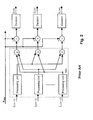
- Fig. 2 shows a schematic block diagram of a stage of a conventional PIC detector.
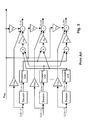
- Fig. 3 shows a schematic block diagram of a stage of a conventional PPIC detector.
- Fig. 4 shows a schematic block diagram of a 2-stage EPIC detector according to a first embodiment of the present invention.
- Fig. 5 shows a flow-chart of the operation of a 3-stage EPIC detector according to a second embodiment of the present invention.
- Fig. 6 shows a graph of the bit error rate BER of a rake receiver alone, a rake receiver with a PIC detector, a rake receiver with a PPIC detector and a rake receiver with an EPIC detector according to the second embodiment of the present invention, as a function of the signal-to-noise ratio in a system with 21 users, a 31-bit Gold code and ideal power control.
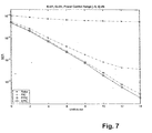
- Fig. 7 shows a graph of the bit error rate BER of a rake receiver alone, a rake receiver with a PIC detector, a rake receiver with a PPIC detector and a rake receiver with an EPIC detector according to the second embodiment of the present invention, as a function of the signal-to-noise ratio in a system with 21 users, a 31-bit Gold code and a power control in the range of [-5, +5]dB.
- Fig. 8 shows a graph of the bit error rate BER of a rake receiver alone, a rake receiver with a PIC detector, a rake receiver with a PPIC detector and a rake receiver with an EPIC detector according to the second embodiment of the present invention, as a function of the signal-to-noise ratio in a system with 31 users, a 31-bit Gold code and ideal power control.
- Fig. 9 shows a graph of the bit error rate BER of a rake receiver alone, a rake receiver with a PIC detector, a rake receiver with a PPIC detector and a rake receiver with an EPIC detector according to the second embodiment of the present invention, as a function of the signal-to-noise ratio in a system with 31 users, a 31-bit Gold code and a power control in the range of [-5, +5] dB.
- The idea of the present invention is to combine and equalize hard-decision outputs of a rake receiver and a 1-stage parallel interference cancellation (PIC) detector in order to achieve a more reliable data estimation.
- According to Fig. 4 showing a block diagram of the present invention and a weighting scheme according to the first embodiment, the signal z Rake output from the rake receiver is subjected to a tentative hard-decision to obtain hard-decision values b Rake in accordance with:
[ b Rake ] k = sgn{[ z Rake ] k }, with k=1, 2, .., K, k being the user index. - The hard-decision values b Rake are subjected to an MAI regeneration which consists of a parallel interference cancellation in accordance with:
- MAI 1 = Fb Rake , F = A H S H SA -diag ([A H S H SA] ii ) off-diagonal cross-correlation matrix.
- The values output by the first MAI regeneration shown in Fig. 4 are subtracted from the rake receiver signal z Rake, and the result is subjected to a tentative hard-decision. The signal b PIC output by the tentative hard-decision is determined as follows:

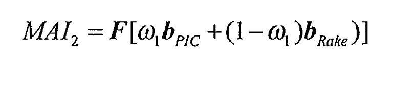
- If [ b Rake]k = [ b PIC]k, these decisions are regarded as highly reliable, and the induced multiple access interference (MAI) is regenerated and fully subtracted from the soft rake receiver outputs z Raxe- If [ b Rake]k ≠ [ b PIC]k, the MAI induced by low-reliability decisions are weighted and fractionally subtracted from z Rake. That is, the second MAI regeneration shown in Fig. 4 is calculated as follows:
- The output signal of the second MAI regeneration is subtracted from z Rake. The subtraction result is subjected to a tentative hard-decision and a first-stage equalized parallel interference cancellation output b EPIC(1) is obtained as follows:

- At the second stage, the hard-decisions b PIC of the 1-stage PIC and the first-stage EPIC detector output b EPIC(1) are equalized. Subsequently, at the third stage, the hard-decisions b EPIC(1) and b EPIC(2) of the first stage and second stage EPIC are equalized, etc., in accordance with the following equation:

with m=2, 3,..,L; and

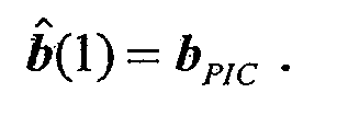
- A more general equation covering the first to Lth stage of the EPIC detector according to the present invention is as follows:

wherein:
m = 2, 3,..,L;

- The EPIC process will be repeated until a predefined number of stages has been completed which relates to the convergence rate or the target bit-error-rate (BER).
- Fig. 5 shows a flow-chart according to a second embodiment of the EPIC detector of the present invention. According to the second and preferred embodiment, the EPIC detector comprises three stages, and the weighting factors of
stages 1 to 3 are chosen to ωm= [0.6;0.7;0.9]. b EPIC(m) (m=1,2,3) is calculated according to the following equation:
- At the first stage, the hard-decision outputs b Rake of the rake receiver are compared with the outputs b PIC of the 1-stage PIC detector by a two-bit-comparator, which consists of only 4 logical gates, for each user. If the two signals are equal, b̂ k is set to [ b PIC]k. If not, b̂ k is set to 0.2[ b PIC]k. The value 0.2=(2ω1-1) is obtained from the weight ω1=0.6 and from the fact that [ b Rake]k = -[ b PIC]k, wherein b̂ k =ω1 b PIC+(1-ω1) b Rake.
- At the second stage, the hard-decision outputs b EPIC(1) and b PIC are compared by a two-bit-comparator for each user. If the two signals are equal, b̂ k is set to [ b EPIC(1)]k. If not, b̂ k is set to 0.4[ b EPIC(1)]k. The value 0.4=(2ω2-1) is obtained from the weight ω2=0.7 and from the fact that b PIC = - b EPIC(1), wherein b k =ω2 b EPIC(1) + (1-ω2) b PIC.
- At the third stage, the hard-decision outputs b EPIC(1) and b EPIC(2) are compared by a two-bit-comparator for each user. If the two signals are equal, b̂ k is set to [ b EPIC(2)]k. If not, b̂ k is set to 0.8[ b EPIC(2)]k. The value 0.8=(2ω3-1) is obtained from the weight ω3=0.9 and from that fact that b EPIC(2) = - b EPIC(1), wherein b̂ k =ω3 b EPIC(2)+(1-ω3)- b EPIC(1).
- The determination of b̂ k can also be made in accordance with:

- The weighting factors ωm=[0.6;0.7;0.9] with the only restriction 0.5<ω1<ω2<ω3 have been tested in simulations, as it is assumed that higher EPIC stages provide more reliable data estimates. The weights at each stage could be varied and predefined in different systems by trail-and-error simulations on training sequences. Furthermore, the weights could be optimized by adaptive schemes.
- Figs. 6 to 9 show simulation results of bit-error-rates (BER) as a function of the signal to noise ratio, the bit error rates being obtained by a rake receiver alone, a conventional 3-stage PIC detector, a conventional 3-stage PPIC detector with ωm=[0.5;0.7;0.9] and the EPIC detector according to the preferred embodiment of the present invention.
- Fig. 6 shows the respective bit-error-rates for the uplink direction and a perfect channel estimation, the number of paths being equal to one, in case of 21 users with ideal power control and a 31-bit Gold code as spreading code.
- Fig. 7 shows the respective bit-error-rates for the uplink direction and a perfect channel estimation, the number of paths being equal to one, in case of 21 users with a power control in the range of [-5,+5]dB and a 31-bit Gold code as spreading code.
- Fig. 8 shows the respective bit-error-rates for the uplink direction and a perfect channel estimation, the number of paths being equal to one, in case of 31 users with ideal power control and a 31-bit Gold code as spreading code.
- Fig. 9 shows the respective bit-error-rates for the uplink direction and a perfect channel estimation, the number of paths being equal to one, in case of 31 users with a power control in the range of [-5,+5]dB and a 31-bit Gold code as spreading code.
- As can be seen from Figs. 6 to 9, the EPIC detector according to the preferred embodiment significantly outperforms the conventional PIC and PPIC detectors. With the EPIC detector according to the present invention, the system performance can be considerably improved especially in heavily loaded systems.
- While the invention has been described with reference to a preferred embodiment, the description is illustrative of the invention and is not to be construed as limiting the invention. Various modifications and applications may occur to those skilled in the art without departing from the true spirit and scope of the invention as defined by the appended claims.
- This application is a divisional application of
European patent application no. 00969445.6 EP-A-1325563 . The original claims of the parent application are repeated below in the present specification and form part of the content of this divisional application as filed. - 1. A method of detecting a spread spectrum composite signal ( r ) comprising plural user signals ( b 1, b 2, .. , b K) that have been spread with spreading codes, said method comprising the steps of:
- a) receiving the composite signal ( r ) at a rake receiver;
- b) obtaining a rake receiver output z Rake= A H S H r ;
- c) producing first hard-decision values b Rake =sgn( z Rake) on the basis of the rake receiver output z Rake;
- d) producing first parallel interference cancellation values z Rake- Fb Rake on the basis of b Rake ;
- e) producing second hard-decision values b PIC =sgn ( z Rake- Fb Rake) on the basis of the first parallel interference cancellation values;
- f) producing first combination values b̂ by combining the hard-decision values b Rake and b PIC;
- g) producing second parallel interference cancellation values z Rake- Fb̂ on the basis of the first combination values b̂ ; and
- h) producing third hard-decision values b̂ EPIC(1) =sgn( z Rake- Fb̂ ) on the basis of the second parallel interference cancellation values, b̂ EPIC(1) being considered to be the output of the equalized parallel interference cancellation (EPIC) detector at a first stage.
- 2. A method according to
claim 1, further comprising the steps of:- i) combining the hard-decision values b EPIC(m) (m=2,3,..,L) at mth stage with the hard-decision values of equalized parallel interference cancellation values b EPIC (m-1) at (m-1)th stage for producing mth combination values b̂ (m) ;
- j) producing (m+1)th parallel interference cancellation values on the basis of the mth combination values b̂ (m) ; and
- k) producing hard-decision values b EPIC(m+1) at (m+1)th stage on the basis of the (m+1)th parallel interference cancellation values.
- 3. A method according to
claim 2, wherein the steps i) to k) are repeated a predetermined number of times. - 4. A method according to
claim 2, wherein the steps i) to k) are repeated until a predetermined bit-error-rate is reached. - 5. A method according to
claim 1, wherein
the first combination values are produced by summing the first and second hard-decision values which are weighted by (1-ω1) and ω1, respectively. - 6. A method according to
claim 1, wherein, for kth user, in case the first hard-decision value equals the second hard-decision value, the second hard-decision value is used as the first combination value,
and wherein in case the first hard-decision value does not equal the second hard-decision value, the first combination value for the kth user is produced by weighting the second hard-decision value with (2ω1-1) - 7. A method according to
claim 2, wherein step i) comprises the steps of:
producing the mth combination values by summing the (m)th and (m+1)th hard-decision values which are weighted by (1-ωm) and ωm, respectively. - 8. A method according to
claim 2, wherein step i) comprises the steps of:- comparing the mth hard-decision values and the (m-1)th hard-decision values of EPIC detector for each user,
and wherein in case the mth hard-decision value does not equal the (m-1)th hard-decision value, the mth combination value is produced by weighting the mth hard-decision value with (2ωm-1). - 9. A method according to claim 7, wherein the mth weighting factor is larger than a (m-1)th weighting factor.
- 10. A method according to
claim 1, wherein the first parallel interference cancellation values are produced by regenerating the induced multiple access interference (MAI) in accordance with:
wherein:- S = spreading code matrix;
- A = channel coefficient matrix;
- ()H = conjugate transpose operation; and
- F = off-diagonal cross-correlation matrix.
- 11. A method according to
claim 6, wherein the second parallel interference cancellation values are produced by regenerating the induced multiple access interference (MAI) in accordance with:

wherein:- S = spreading code matrix;
- A = channel coefficient matrix;
- ()H = conjugate transpose operation; and
- F = off-diagonal cross-correlation matrix.
- 12. A method according to
claim 8, wherein the (m+1)th parallel interference cancellation values are produced by regenerating the induced multiple access interference (MAI) in accordance with:
wherein:- S = spreading code matrix;
- A = channel coefficient matrix;
- ()H = conjugate transpose operation; and
- F = off-diagonal cross-correlation matrix.
- 13. A method according to claim 5 or 7, wherein the weighting factors at each stage m are varied and predefined in different systems by trail-and-error simulations on training sequences and optimized by adaptive schemes.
- 14. A method according to claim 5 or 7, wherein the weighting factors are defined by power of 2.
- 15. A detecting device for detecting a spread spectrum composite signal ( r ) comprising plural user signals ( b 1, b 2, .., b K) that have been spread with spreading codes, the composite signal ( r ) being received at a rake receiver which provides a rake receiver output z Rake= A H S H r, said detecting device being arranged to:
- a) produce first hard-decision values b Rake =sgn( z Rake) on the basis of the rake receiver output z Rake;
- b) produce first parallel interference cancellation values Z Rake- Fb Rake on the basis of b Rake ;
- c) produce second hard-decision values b PIC =sgn (z Rake- Fb Rake) on the basis of the first parallel interference cancellation values;
- d) produce first combination values b̂ by combining the hard-decision values b Rake and b PIC ;
- e) produce second parallel interference cancellation values z Rake- Fb̂ on the basis of the first combination values b̂ ; and
- f) produce third hard-decision values b̂ EPIC(1) =sgn ( z Rake- Fb̂ ) on the basis of the second parallel interference cancellation values, b̂ EPIC(1) being considered to be the output of the equalized parallel interference cancellation (EPIC) detector at a first stage.
- 16. A device according to claim 15, further being arranged to:
- g) combine the hard-decision values b EPIC(m) (m=2,3,..,L) at mth stage with the hard-decision values of equalized parallel interference cancellation values b EPIC(m-1) at (m-1)th stage for producing mth combination values b̂ (m);
- h) produce (m+1)th parallel interference cancellation values on the basis of the mth combination values b̂ (m); and
- i) produce hard-decision values b EPIC(m+1) at (m+1)th stage on the basis of the (m+1)th parallel interference cancellation values.
- 17. A device according to claim 16, wherein the device repeats the steps g) to i) a predetermined number of times.
- 18. A device according to claim 16, wherein the device repeats the steps g) to i) until a predetermined bit-error-rate is reached.
- 19. A device according to claim 15, wherein the first combination values are produced by summing the first and second hard-decision values which are weighted by (1-ω1) and ω1, respectively.
- 20. A device according to claim 15, wherein, for kth user, in case the first hard-decision value equals the second hard-decision value, the device uses the second hard-decision value as the first combination value,
and wherein in case the first hard-decision value does not equal the second hard-decision value, the device produces the first combination value for the kth user by weighting the second hard-decision value with (2ω1-1) - 21. A device according to claim 16, wherein in performing step g) the device is arranged to:
produce the mth combination values by summing the (m)th and (m+1)th hard-decision values which are weighted by (1-ωm) and ωm, respectively. - 22. A device according to claim 16, wherein in performing step g) the device is arranged to:
- compare the mth hard-decision values and the (m-1)th hard-decision values of EPIC detector for each user,
and wherein in case the mth hard-decision value does not equal the (m-1)th hard-decision value, the device produces the mth combination value by weighting the mth hard-decision value with (2ωm-1). - 23. A device according to claim 22, wherein the mth weighting factor is larger than a (m-1)th weighting factor.
- 24. A device according to claim 15, wherein the device produces the first parallel interference cancellation values by regenerating the induced multiple access interference (MAI) in accordance with:

wherein:- S = spreading code matrix;
- A = channel coefficient matrix;
- ()H = conjugate transpose operation; and
- F = off-diagonal cross-correlation matrix.
- 25. A device according to claim 20, wherein the device produces the second parallel interference cancellation values by regenerating the induced multiple access interference (MAI) in accordance with:


wherein:- S = spreading code matrix;
- A = channel coefficient matrix;
- ()H = conjugate transpose operation; and
- F = off-diagonal cross-correlation matrix.
- 26. A device according to claim 22, wherein the device produces the (m+1)th parallel interference cancellation values by regenerating the induced multiple access interference (MAI) in accordance with:

wherein:- S = spreading code matrix;
- A = channel coefficient matrix;
- ()H = conjugate transpose operation; and
- F = off-diagonal cross-correlation matrix.
- 27. A device according to claim 19 or 21, wherein the weighting factors at each stage m are varied and predefined in different systems by trail-and-error simulations on training sequences and optimized by adaptive schemes.
- 28. A device according to claim 19 or 21, wherein the weighting factors are defined by power of 2.
- 29. An apparatus comprising a rake receiver and a detecting device according to any one of claims 15 to 28.
Claims (25)
- A method of detecting a spread spectrum composite signal ( r ) comprising plural user signals ( b 1, b 2,... b K) that have been spread with spreading codes, said method comprising the steps of:a) receiving the composite signal ( r ) at a rake receiver;b) obtaining a rake receiver output z Rake= A H S H r ;c) producing first hard-decision values b Rake =sgn( z Rake) on the basis of the rake receiver output z Rake ;d) producing first parallel interference cancellation values z Rake- Fb Rake on the basis of b Rake;e) producing second hard-decision values b PIC =sgn(z Rake- Fb Rake) on the basis of the first parallel interference cancellation values;f) producing first combination values b̂ by combining the hard-decision values b Rake and b PIC;g) producing second parallel interference cancellation values z Rake- Fb̂ on the basis of the first combination values b̂ ; andh) producing third hard-decision values b̂ EPIC(1) =sgn ( z Rake- Fb̂ ) on the basis of the second parallel interference cancellation values, b̂ EPIC(1) being considered to be the output of the equalized parallel interference cancellation (EPIC) detector at a first stage,wherein the first parallel interference cancellation values are produced by regenerating the induced multiple access interference (MAI) in accordance with:

wherein:S = spreading code matrix;A = channel coefficient matrix;()H = conjugate transpose operation; andF = off-diagonal cross-correlation matrix. - A method according to claim 1, further comprising the steps of:i) combining the hard-decision values b EPIC(m) (m=2,3,..,L) at mth stage with the hard-decision values of equalized parallel interference cancellation values b EPIC(m-1) at (m-1)th stage for producing mth combination values b̂ (m);j) producing (m+1)th parallel interference cancellation values on the basis of the mth combination values b̂ (m); andk) producing hard-decision values b EPIC(m+1) at (m+1)th stage on the basis of the (m+1)th parallel interference cancellation values.
- A method according to claim 1, wherein, for kth user, in case the first hard-decision value equals the second hard-decision value, the second hard-decision value is used as the first combination value,
and wherein in case the first hard-decision value does not equal the second hard-decision value, the first combination value for the kth user is produced by weighting the second hard-decision value with (2ω1-1), wherein ω1 is a weighting factor, wherein the second parallel interference cancellation values are produced by
regenerating the induced multiple access interference (MAI) in accordance with:
- A method according to claim 2, wherein the steps i) to k) are repeated a predetermined number of times.
- A method according to claim 2, wherein the steps i) to k) are repeated until a predetermined bit-error-rate is reached.
- A method according to claim 1, wherein
the first combination values are produced by summing the first and second hard-decision values which are weighted by (1-ω1) and ω1, respectively, wherein ω1 is a weighting factor. - A method according to claim 2, wherein step i) comprises the steps of:producing the mth combination values by summing the (m)th and (m+1)th hard-decision values which are weighted by (1-ωm) and ωm, respectively, wherein ωm is a weighting factor.
- A method according to claim 2, wherein step i) comprises the steps of:comparing the mth hard-decision values and the (m-1)th hard-decision values of EPIC detector for each user,wherein, for user k, in case the mth hard-decision value equals the (m-1)th hard-decision value, the mth hard-decision value is used as the mth combination value,
and wherein in case the mth hard-decision value does not equal the (m-1)th hard-decision value, the mth combination value is produced by weighting the mth hard-decision value with (2ωm-1), wherein ωm is a weighting factor. - A method according to claim 7, wherein the mth weighting factor is larger than a (m-1)th weighting factor.
- A method according to claim 8, wherein the (m+1)th parallel interference cancellation values are produced by regenerating the induced multiple access interference (MAI) in accordance with:

- A method according to claim 6 or 7, wherein the weighting factors at each stage m are varied and predefined in different systems by trail-and-error simulations on training sequences and optimized by adaptive schemes.
- A method according to claim 6 or 7, wherein the weighting factors are defined by power of 2.
- A detecting device for detecting a spread spectrum composite signal ( r ) comprising plural user signals ( b 1 ,b 2,.., b K) that have been spread with spreading codes, the composite signal ( r ) being received at a rake receiver which provides a rake receiver output z Rake= A H S H r, said detecting device being arranged to:a) produce first hard-decision values b Rake =sgn( z Rake) on the basis of the rake receiver output z Rake ;b) produce first parallel interference cancellation values z Rake- Fb Rake on the basis of b Rake ;c) produce second hard-decision values b PIC =sgn ( z Rake- Fb Rake) on the basis of the first parallel interference cancellation values;d) produce first combination values b̂ by combining the hard-decision values b Rake and b PIC ;e) produce second parallel interference cancellation values z Rake -Fb̂ on the basis of the first combination values b̂ ; andf) produce third hard-decision values b̂ EPIC(1) =sgn( z Rake- Fb̂ ) on the basis of the second parallel interference cancellation values, b̂ EPIC(1) being considered to be the output of the equalized parallel interference cancellation (EPIC) detector at a first stage, wherein the device produces the first parallel interference cancellation values by regenerating the induced multiple access interference (MAI) in accordance with:wherein:
 S = spreading code matrix;A = channel coefficient matrix;()H = conjugate transpose operation; andF = off-diagonal cross-correlation matrix.
 - A device according to claim 13, further being arranged to:g) combine the hard-decision values b IPIC(m) (m=2,3,..,L) at mth stage with the hard-decision values of equalized parallel interference cancellation values b EPIC(m-1) at (m-1)th stage for producing mth combination values b̂ (m);h) produce (m+1)th parallel interference cancellation values on the basis of the mth combination values b̂ (m) ; andi) produce hard-decision values b EPIC(m+1) at (m+1)th stage on the basis of the (m+1)th parallel interference cancellation values.
- A device according to claim 13, wherein, for kth user, in case the first hard-decision value equals the second hard-decision value, the device uses the second hard-decision value as the first combination value,
and wherein in case the first hard-decision value does not equal the second hard-decision value, the device produces the first combination value for the kth user by weighting the second hard-decision value with (2ω1-1), wherein ω1 is a weighting factor, wherein the device produces the second parallel interference cancellation values by regenerating the induced multiple access interference (MAI) in accordance with:
- A device according to claim 14, wherein the device repeats the steps g) to i) a predetermined number of times.
- A device according to claim 14, wherein the device repeats the steps g) to i) until a predetermined bit-error-rate is reached.
- A device according to claim 13, wherein the first combination values are produced by summing the first and second hard-decision values which are weighted by (1-ω1) and ω1, respectively, wherein ω1 is a weighting factor.
- A device according to claim 14, wherein in performing step g) the device is arranged to:produce the mth combination values by summing the (m)th and (m+1)th hard-decision values which are weighted by (1-ωm) and ωm, respectively, wherein ωm is a weighting factor.
- A device according to claim 14, wherein in performing step g) the device is arranged to:compare the mth hard-decision values and the (m-1)th hard-decision values of EPIC detector for each user,wherein, for user k, in case the mth hard-decision value equals the (m-1)th hard-decision value, the device uses the mth hard-decision value as the mth combination value,
and wherein in case the mth hard-decision value does not equal the (m-1)th hard-decision value, the device produces the mth combination value by weighting the mth hard-decision value with (2ωm-1), wherein ωm is a weighting factor. - A device according to claim 20, wherein the mth weighting factor is larger than a (m-1)th weighting factor.
- A device according to claim 20, wherein the device produces the (m+1)th parallel interference cancellation values by regenerating the induced multiple access interference (MAI) in accordance with:

- A device according to claim 18 or 19, wherein the weighting factors at each stage m are varied and predefined in different systems by trail-and-error simulations on training sequences and optimized by adaptive schemes.
- A device according to claim 18 or 19, wherein the weighting factors are defined by power of 2.
- An apparatus comprising a rake receiver and a detecting device according to any one of claims 13 to 24.
Priority Applications (1)
| Application Number | Priority Date | Filing Date | Title |
|---|---|---|---|
| DE60042249T DE60042249D1 (en) | 1999-08-31 | 2000-10-06 | Balanced parallel interference cancellation for CDMA systems |
Applications Claiming Priority (3)
| Application Number | Priority Date | Filing Date | Title |
|---|---|---|---|
| US09/386,879 US6439669B1 (en) | 1999-08-31 | 1999-08-31 | Filament gripper |
| PCT/US2000/023465 WO2001015569A1 (en) | 1999-08-31 | 2000-08-25 | Filament gripper |
| EP00969445A EP1325563B1 (en) | 2000-10-06 | 2000-10-06 | Equalized parallel interference cancellation for cdma systems |
Related Parent Applications (1)
| Application Number | Title | Priority Date | Filing Date |
|---|---|---|---|
| EP00969445A Division EP1325563B1 (en) | 1999-08-31 | 2000-10-06 | Equalized parallel interference cancellation for cdma systems |
Publications (2)
| Publication Number | Publication Date |
|---|---|
| EP1892842A1 true EP1892842A1 (en) | 2008-02-27 |
| EP1892842B1 EP1892842B1 (en) | 2009-05-20 |
Family
ID=23527449
Family Applications (2)
| Application Number | Title | Priority Date | Filing Date |
|---|---|---|---|
| EP00959445A Expired - Lifetime EP1211964B1 (en) | 1999-08-31 | 2000-08-25 | Filament gripper |
| EP07122752A Expired - Lifetime EP1892842B1 (en) | 1999-08-31 | 2000-10-06 | Equalized parallel interference cancellation for cdma systems |
Family Applications Before (1)
| Application Number | Title | Priority Date | Filing Date |
|---|---|---|---|
| EP00959445A Expired - Lifetime EP1211964B1 (en) | 1999-08-31 | 2000-08-25 | Filament gripper |
Country Status (10)
| Country | Link |
|---|---|
| US (1) | US6439669B1 (en) |
| EP (2) | EP1211964B1 (en) |
| JP (1) | JP2003508101A (en) |
| CN (1) | CN100479705C (en) |
| AT (1) | ATE308260T1 (en) |
| AU (1) | AU7077000A (en) |
| BR (1) | BR0013538A (en) |
| DE (2) | DE60023719T2 (en) |
| ES (1) | ES2246885T3 (en) |
| WO (1) | WO2001015569A1 (en) |
Families Citing this family (3)
| Publication number | Priority date | Publication date | Assignee | Title |
|---|---|---|---|---|
| US6893100B1 (en) * | 2000-09-19 | 2005-05-17 | Gillett Canada Company | Methods and apparatus for automated brush assembly |
| DE10207019A1 (en) | 2002-02-20 | 2003-09-11 | Braun Gmbh | Clamping device and method for holding filament tufts |
| CN102309134B (en) * | 2010-07-02 | 2013-09-25 | 珠海市庭佑化妆配件有限公司 | Manufacturing method of hair brush |
Citations (2)
| Publication number | Priority date | Publication date | Assignee | Title |
|---|---|---|---|---|
| US5644592A (en) | 1995-04-24 | 1997-07-01 | California Institute Of Technology | Parallel interference cancellation for CDMA applications |
| WO2000072459A1 (en) | 1999-05-24 | 2000-11-30 | Nokia Networks Oy | Method and apparatus for providing differential multistage detection in the reverse link of a code division multiple access communication system |
Family Cites Families (24)
| Publication number | Priority date | Publication date | Assignee | Title |
|---|---|---|---|---|
| GB247688A (en) | 1924-12-08 | 1926-02-25 | Briton Brush Company Ltd | Improvements relating to brush making machines |
| US2015326A (en) | 1932-07-27 | 1935-09-24 | Steidle Anton | Machine for inserting bristles in ferrules |
| US2187791A (en) | 1938-05-07 | 1940-01-23 | Ox Fibre Brush Company Inc | Brush making machine |
| DE2308399A1 (en) | 1973-02-21 | 1974-08-22 | Klaus Josef | DEVICE FOR INTRODUCING A BUNCH OF BRISTLES INTO A HEATING PANEL |
| EP0149996A3 (en) | 1984-01-10 | 1987-10-21 | Schlesinger GmbH & Co. Maschinenbau KG | Method and machine for manufacturing brushes |
| BE901006A (en) | 1984-11-08 | 1985-05-08 | Boucherie Nv G B | AUTOMATIC FILLING DEVICE FOR FIBER MAGAZINE AND / OR BRUSHES OF BRUSH MANUFACTURING MACHINES. |
| BE902517A (en) * | 1985-05-29 | 1985-09-16 | Boucherie Nv G B | Brush bristles loading system into magazine - alters shape of bundle during fitting into magazine channel |
| JPS62148610A (en) | 1985-11-19 | 1987-07-02 | 株式会社 新和製作所 | Production of fiber bundle for brush |
| US4884849A (en) | 1988-12-12 | 1989-12-05 | Better Health Concepts Co Inc. | Apparatus for manufacture of end brush |
| US5148568A (en) | 1989-08-31 | 1992-09-22 | Professional Dental Technologies, Corp. | Apparatus and method for making an end brush with a male projection |
| DE4006325A1 (en) * | 1990-03-01 | 1991-09-05 | Schlerf Coronet Werke | BRUSH MACHINING |
| IL96413A0 (en) * | 1990-11-20 | 1991-08-16 | Ohad Paz | Brush including spring-mounted bristle holders |
| US5221123A (en) | 1991-04-24 | 1993-06-22 | Klinkhammer Ronald W | Bristles clusters, brushes, and their manufacture |
| US5224763A (en) | 1991-12-30 | 1993-07-06 | The Procter & Gamble Company | Method of fastening bristle tufts to bristle carrier |
| GB2287901B (en) | 1994-03-29 | 1998-05-06 | Boucherie Nv G B | A brush making machine |
| DE4415886A1 (en) | 1994-05-05 | 1995-11-09 | Coronet Werke Gmbh | Process for the production of bristle goods by injection molding |
| GB2289236B (en) | 1994-05-09 | 1997-08-06 | Boucherie Nv G B | A brush making machine |
| BE1009283A3 (en) * | 1995-04-05 | 1997-01-07 | Boucherie Nv G B | METHOD AND DEVICE FOR WORKING brushes. |
| DE19538621A1 (en) * | 1995-10-17 | 1997-04-24 | Zahoransky Anton Gmbh & Co | Brush making method, especially toothbrush |
| US5927819A (en) * | 1997-02-28 | 1999-07-27 | Gillette Canada Inc. | Method and device for trimming and end-rounding bristles |
| DE19745952B4 (en) * | 1997-10-17 | 2008-07-31 | Anton Zahoransky Gmbh & Co. | Toothbrush manufacturing machine |
| BE1011547A3 (en) * | 1997-11-14 | 1999-10-05 | Boucherie Nv G B | APPARATUS FOR SUPPLYING FIBERS TO A FILLING MACHINE AT A BRUSH MANUFACTURING MACHINE. |
| JPH11206459A (en) * | 1998-01-27 | 1999-08-03 | Kao Corp | Brush manufacturing method |
| ES2200491T3 (en) | 1998-07-14 | 2004-03-01 | Firma G.B. Boucherie, Naamloze Vennootschap | METHOD FOR THE MANUFACTURE OF BRUSHES AND MACHINE FOR THE MANUFACTURE OF BRUSHES APPLYING SUCH METHOD. |
-
1999
- 1999-08-31 US US09/386,879 patent/US6439669B1/en not_active Expired - Lifetime
-
2000
- 2000-08-25 EP EP00959445A patent/EP1211964B1/en not_active Expired - Lifetime
- 2000-08-25 BR BR0013538-0A patent/BR0013538A/en not_active Application Discontinuation
- 2000-08-25 JP JP2001519794A patent/JP2003508101A/en active Pending
- 2000-08-25 AT AT00959445T patent/ATE308260T1/en not_active IP Right Cessation
- 2000-08-25 ES ES00959445T patent/ES2246885T3/en not_active Expired - Lifetime
- 2000-08-25 CN CN00812117.6A patent/CN100479705C/en not_active Expired - Fee Related
- 2000-08-25 WO PCT/US2000/023465 patent/WO2001015569A1/en not_active Ceased
- 2000-08-25 DE DE60023719T patent/DE60023719T2/en not_active Expired - Lifetime
- 2000-08-25 AU AU70770/00A patent/AU7077000A/en not_active Abandoned
- 2000-10-06 EP EP07122752A patent/EP1892842B1/en not_active Expired - Lifetime
- 2000-10-06 DE DE60042249T patent/DE60042249D1/en not_active Expired - Lifetime
Patent Citations (2)
| Publication number | Priority date | Publication date | Assignee | Title |
|---|---|---|---|---|
| US5644592A (en) | 1995-04-24 | 1997-07-01 | California Institute Of Technology | Parallel interference cancellation for CDMA applications |
| WO2000072459A1 (en) | 1999-05-24 | 2000-11-30 | Nokia Networks Oy | Method and apparatus for providing differential multistage detection in the reverse link of a code division multiple access communication system |
Non-Patent Citations (1)
| Title |
|---|
| DIVASALAR D ET AL: "IMPROVED PARALLEL INTERFERENCE CANCELLATION FOR CDMA", IEEE TRANSACTIONS ON COMMUNICATIONS,IEEE INC. NEW YORK,US, vol. 46, no. 2, 1 February 1998 (1998-02-01), pages 258 - 268, XP000734697, ISSN: 0090-6778 * |
Also Published As
| Publication number | Publication date |
|---|---|
| DE60023719D1 (en) | 2005-12-08 |
| US6439669B1 (en) | 2002-08-27 |
| AU7077000A (en) | 2001-03-26 |
| JP2003508101A (en) | 2003-03-04 |
| EP1211964A1 (en) | 2002-06-12 |
| CN100479705C (en) | 2009-04-22 |
| DE60042249D1 (en) | 2009-07-02 |
| BR0013538A (en) | 2002-05-07 |
| ES2246885T3 (en) | 2006-03-01 |
| WO2001015569A1 (en) | 2001-03-08 |
| DE60023719T2 (en) | 2006-07-20 |
| EP1211964B1 (en) | 2005-11-02 |
| EP1892842B1 (en) | 2009-05-20 |
| ATE308260T1 (en) | 2005-11-15 |
| WO2001015569A9 (en) | 2002-09-06 |
| CN1371251A (en) | 2002-09-25 |
Similar Documents
| Publication | Publication Date | Title |
|---|---|---|
| Buehrer et al. | A simulation comparison of multiuser receivers for cellular CDMA | |
| Hui et al. | Successive interference cancellation for multiuser asynchronous DS/CDMA detectors in multipath fading links | |
| EP0925652B1 (en) | Coherent demodulation with decision-directed channel estimation for digital communication | |
| Wei et al. | Near optimum tree-search detection schemes for bit-synchronous multiuser CDMA systems over Gaussian and two-path Rayleigh-fading channels | |
| US8548028B2 (en) | Method and apparatus for equalizing CDMA signals | |
| JP5346074B2 (en) | Method and apparatus for successive interference cancellation with covariance route processing | |
| EP1274177B1 (en) | Method and apparatus for regenerative based interference cancellation within a communication system | |
| Buehrer et al. | A comparison of multiuser receivers for cellular CDMA | |
| JP3275079B2 (en) | Method and apparatus for coherent channel estimation in a communication system | |
| US7133435B2 (en) | Interference cancellation system and method | |
| Buehrer et al. | Comments on" Partial parallel interference cancellation for CDMA" | |
| WO2002013395A2 (en) | Spreading factor detector | |
| US7167529B2 (en) | Method and device for radio signal reception | |
| Brunel et al. | Lattice decoding for joint detection in direct-sequence CDMA systems | |
| JP4205761B2 (en) | Interference cancellation method and receiver | |
| EP1325563B1 (en) | Equalized parallel interference cancellation for cdma systems | |
| EP1892842B1 (en) | Equalized parallel interference cancellation for cdma systems | |
| US7298801B2 (en) | Method and device for demodulating signals from multiple users | |
| McCormick et al. | Hybrid uplink multi-carrier CDMA interference-cancellation receiver | |
| Ko et al. | Performance analysis for multistage interference cancellers in asynchronous DS-CDMA systems | |
| Hong et al. | Analysis of a pipelined successive interference cancellation scheme for a DS/CDMA system | |
| Boulanger et al. | Multistage linear DS-CDMA receivers | |
| Soong et al. | CDMA multi-user interference cancellation with reference symbol aided estimation of channel parameters | |
| Sheikh et al. | DS-CDMA system with linear multiuser detection in AWGN channel | |
| US6621856B1 (en) | Method of receiving CDMA signals with parallel interference suppression, and corresponding stage and receiver |
Legal Events
| Date | Code | Title | Description |
|---|---|---|---|
| PUAI | Public reference made under article 153(3) epc to a published international application that has entered the european phase |
Free format text: ORIGINAL CODE: 0009012 |
|
| AC | Divisional application: reference to earlier application |
Ref document number: 1325563 Country of ref document: EP Kind code of ref document: P |
|
| AK | Designated contracting states |
Kind code of ref document: A1 Designated state(s): DE ES FR GB IT SE |
|
| 17P | Request for examination filed |
Effective date: 20080611 |
|
| 17Q | First examination report despatched |
Effective date: 20080710 |
|
| RIN1 | Information on inventor provided before grant (corrected) |
Inventor name: LILLEBERG, JORMA Inventor name: WANG, HAIFENG Inventor name: BU, ZHIYONG |
|
| AKX | Designation fees paid |
Designated state(s): DE GB |
|
| GRAP | Despatch of communication of intention to grant a patent |
Free format text: ORIGINAL CODE: EPIDOSNIGR1 |
|
| GRAS | Grant fee paid |
Free format text: ORIGINAL CODE: EPIDOSNIGR3 |
|
| GRAA | (expected) grant |
Free format text: ORIGINAL CODE: 0009210 |
|
| AC | Divisional application: reference to earlier application |
Ref document number: 1325563 Country of ref document: EP Kind code of ref document: P |
|
| AK | Designated contracting states |
Kind code of ref document: B1 Designated state(s): DE GB |
|
| REG | Reference to a national code |
Ref country code: GB Ref legal event code: FG4D |
|
| REF | Corresponds to: |
Ref document number: 60042249 Country of ref document: DE Date of ref document: 20090702 Kind code of ref document: P |
|
| PGFP | Annual fee paid to national office [announced via postgrant information from national office to epo] |
Ref country code: GB Payment date: 20090930 Year of fee payment: 10 |
|
| PGFP | Annual fee paid to national office [announced via postgrant information from national office to epo] |
Ref country code: DE Payment date: 20091001 Year of fee payment: 10 |
|
| PLBE | No opposition filed within time limit |
Free format text: ORIGINAL CODE: 0009261 |
|
| STAA | Information on the status of an ep patent application or granted ep patent |
Free format text: STATUS: NO OPPOSITION FILED WITHIN TIME LIMIT |
|
| 26N | No opposition filed |
Effective date: 20100223 |
|
| GBPC | Gb: european patent ceased through non-payment of renewal fee |
Effective date: 20101006 |
|
| PG25 | Lapsed in a contracting state [announced via postgrant information from national office to epo] |
Ref country code: GB Free format text: LAPSE BECAUSE OF NON-PAYMENT OF DUE FEES Effective date: 20101006 |
|
| REG | Reference to a national code |
Ref country code: DE Ref legal event code: R119 Ref document number: 60042249 Country of ref document: DE Effective date: 20110502 |
|
| PG25 | Lapsed in a contracting state [announced via postgrant information from national office to epo] |
Ref country code: DE Free format text: LAPSE BECAUSE OF NON-PAYMENT OF DUE FEES Effective date: 20110502 |