EP1892678A2 - Bill handling apparatus - Google Patents
Bill handling apparatus Download PDFInfo
- Publication number
- EP1892678A2 EP1892678A2 EP07016278A EP07016278A EP1892678A2 EP 1892678 A2 EP1892678 A2 EP 1892678A2 EP 07016278 A EP07016278 A EP 07016278A EP 07016278 A EP07016278 A EP 07016278A EP 1892678 A2 EP1892678 A2 EP 1892678A2
- Authority
- EP
- European Patent Office
- Prior art keywords
- bill
- light
- emitting
- handling apparatus
- guide member
- Prior art date
- Legal status (The legal status is an assumption and is not a legal conclusion. Google has not performed a legal analysis and makes no representation as to the accuracy of the status listed.)
- Granted
Links
Images




Classifications
-
- G—PHYSICS
- G07—CHECKING-DEVICES
- G07D—HANDLING OF COINS OR VALUABLE PAPERS, e.g. TESTING, SORTING BY DENOMINATIONS, COUNTING, DISPENSING, CHANGING OR DEPOSITING
- G07D11/00—Devices accepting coins; Devices accepting, dispensing, sorting or counting valuable papers
- G07D11/10—Mechanical details
- G07D11/14—Inlet or outlet ports
-
- B—PERFORMING OPERATIONS; TRANSPORTING
- B65—CONVEYING; PACKING; STORING; HANDLING THIN OR FILAMENTARY MATERIAL
- B65H—HANDLING THIN OR FILAMENTARY MATERIAL, e.g. SHEETS, WEBS, CABLES
- B65H43/00—Use of control, checking, or safety devices, e.g. automatic devices comprising an element for sensing a variable
-
- G—PHYSICS
- G07—CHECKING-DEVICES
- G07D—HANDLING OF COINS OR VALUABLE PAPERS, e.g. TESTING, SORTING BY DENOMINATIONS, COUNTING, DISPENSING, CHANGING OR DEPOSITING
- G07D7/00—Testing specially adapted to determine the identity or genuineness of valuable papers or for segregating those which are unacceptable, e.g. banknotes that are alien to a currency
- G07D7/06—Testing specially adapted to determine the identity or genuineness of valuable papers or for segregating those which are unacceptable, e.g. banknotes that are alien to a currency using wave or particle radiation
- G07D7/12—Visible light, infrared or ultraviolet radiation
-
- B—PERFORMING OPERATIONS; TRANSPORTING
- B65—CONVEYING; PACKING; STORING; HANDLING THIN OR FILAMENTARY MATERIAL
- B65H—HANDLING THIN OR FILAMENTARY MATERIAL, e.g. SHEETS, WEBS, CABLES
- B65H2404/00—Parts for transporting or guiding the handled material
- B65H2404/60—Other elements in face contact with handled material
- B65H2404/61—Longitudinally-extending strips, tubes, plates, or wires
- B65H2404/611—Longitudinally-extending strips, tubes, plates, or wires arranged to form a channel
-
- B—PERFORMING OPERATIONS; TRANSPORTING
- B65—CONVEYING; PACKING; STORING; HANDLING THIN OR FILAMENTARY MATERIAL
- B65H—HANDLING THIN OR FILAMENTARY MATERIAL, e.g. SHEETS, WEBS, CABLES
- B65H2553/00—Sensing or detecting means
- B65H2553/40—Sensing or detecting means using optical, e.g. photographic, elements
- B65H2553/44—Involving light guide, e.g. optical fibres
-
- B—PERFORMING OPERATIONS; TRANSPORTING
- B65—CONVEYING; PACKING; STORING; HANDLING THIN OR FILAMENTARY MATERIAL
- B65H—HANDLING THIN OR FILAMENTARY MATERIAL, e.g. SHEETS, WEBS, CABLES
- B65H2701/00—Handled material; Storage means
- B65H2701/10—Handled articles or webs
- B65H2701/19—Specific article or web
- B65H2701/1912—Banknotes, bills and cheques or the like
Definitions
- the present invention relates to a bill handling apparatus for feeding a bill inserted from a bill insertion slot, while reading the fed bill to identify the validity.
- a bill handling apparatus identifies the validity of a bill inserted from a bill insertion slot by a user, and is incorporated into service apparatuses that provides various kinds of products and service corresponding to the bill value judged as being valid, such as, for example, a game media lending machine installed in a game hole, or an automatic dispenser, ticket-vending machine and the like installed in public areas.
- the bill handling apparatus is usually provided with operation devices such as a bill feeding mechanism that feeds a bill inserted into a bill insertion slot, bill reading means for executing readout of the fed bill, bill identifying means for identifying the validity (also referred to as authentication judgment) from the read bill information and the like, and control means for driving and controlling the operation devices.
- operation devices such as a bill feeding mechanism that feeds a bill inserted into a bill insertion slot, bill reading means for executing readout of the fed bill, bill identifying means for identifying the validity (also referred to as authentication judgment) from the read bill information and the like, and control means for driving and controlling the operation devices.
- the above-mentioned bill reading means is provided with a photosensor which applies light to the fed bill and detects the reflected light and/or transmitted light, and the bill identifying means compares a detection signal from the photosensor with beforehand stored authorized bill data to identify the validity.
- the bill identification accuracy is improved by detecting the entire width direction of the fed bill.
- 2001-357429 is a technique for forming the bill reading means comprised of the so-called line sensor formed of a light-emitting portion that irradiates almost the entire region of a passage width of the bill in the shape of a slit, and a light-receiving portion comprised of a photodiode array, reading information of the entire width of the passed bill, and thereby improving the identification accuracy of the validity.
- the light-emitting portion that irradiates in the shape of a slit is comprised of a light guide member that extends in the width direction of the fed bill and that receives at its one end the light applied from at least one LED, such a light guide member and light-receiving portion are disposed opposite to each other with a bill feeding path positioned therebetween, or disposed in parallel with each other on one side of the bill feeding path, and readout of the bill information is thereby executed.
- a bill handling apparatus is characterized by comprising a frame provided with a bill feeding path in which a bill is fed and with a side wall portion provided in a width direction of the bill feeding path, a bill reading section installed in the frame to read a fed bill, and a bill identifying section for identifying authentication of the bill read by the bill reading section, where the bill reading section is provided with a light guide member to which light is input from a light-emitting device as a light-emitting portion that applies the light to the fed bill, and the light guide member is installed to enter inside the side wall portion.
- FIGs.1 to 4 are views showing a configuration of a bill handling apparatus according to this embodiment
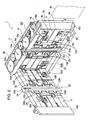
- FIG.1 is a perspective view showing an entire configuration
- FIG.2 is a perspective view showing a state where an upper frame is opened with respect to a lower frame
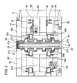
- FIG.3 is a plan view showing a bill feeding path portion of the lower frame
- FIG.4 is a rear elevational view of the lower frame.
- a bill handling apparatus 1 of this embodiment is configured to be capable of being incorporated into a game media lending apparatus (not shown) installed among various kinds of game machines such as, for example, slot machines and the like.
- the game media lending apparatus may be provided with another apparatus (for example, a bill storage unit, coin identifying apparatus, storage media processing apparatus, power supply apparatus and the like) on the upper or lower side of the bill handling apparatus 1, and the bill handling apparatus 1 may be formed integrally with the other apparatus, or formed separately. Then, when a bill is inserted in such a bill handling apparatus 1 and the validity of the inserted bill is judged, the processing corresponding to the bill value is performed such as the processing for lending game media, the processing of writing in a storage medium such as a prepaid card, or like.
- the bill handling apparatus 1 is provided with a frame 2 formed in the shape of a substantially cuboid, and the frame 2 is mounted to a locking portion of the game media lending apparatus not shown in the figure.
- the frame 2 has a lower frame 2B as a base side and an upper frame 2Aopenable/closable with respect to the lower frame 2B to cover the lower frame 2B.
- the frames 2A and 2B are configured to be opened and closed with a base portion as a turn center as shown in FIG.2.
- the lower frame 2B has the shape of a substantially cuboid, and is provided with a bill feeding face 3a for feeding a bill, and side wall portions 3b formed on the opposite sides of the bill feeding face 3a.
- the upper frame 2A is configured in the shape of a plate provided with a bill feeding face 3c, and when the upper frame 2A is closed to enter between the side wall portions 3b on the opposite sides of the lower frame 2B, a clearance (bill feeding path) 5 to feed a bill is formed between opposite portions of the bill feeding face 3a and bill feeding face 3c.
- the upper frame 2A and lower frame 2B are respectively provided with bill insertion portions 6A and 6B adapted to the bill feeding path 5.
- These bill insertion portions 6A and 6B form a bill insertion slot 6 in the shape of a slit when the upper frame 2A and lower frame 2B are closed, and as shown in FIG.1, a bill M is inserted inside from a shorter side of the bill along the direction of allow A.
- a lock shaft 4 capable of locking in the lower frame 2B is disposed on the front end side of the upper frame 2A.
- the lock shaft 4 is provided with an operation portion 4a, and by operating the operation portion 4a to rotate against the biasing force of a biasing spring 4b, rotates on a pivot P as a center to release the lock state of the upper frame 2A and lower frame 2B (the state where the frames are closed: overlapping state).
- a bill feeding mechanism 8 In the lower frame 2B are provided a bill feeding mechanism 8, a bill detecting sensor 18 that detects a bill inserted in the bill insertion slot 6, bill reading means(a bill reading section) 20 that is installed on the downstream side of the bill detecting sensor 18 and that reads information of the bill in a fed state, a shutter mechanism 50 that is installed in the bill feeding path 5 between the bill insertion slot 6 and the bill detecting sensor 18 and that is driven to block the bill insertion slot 6, and control means (circuit control board(a bill identifying section)) 100 for controlling driving of structural members such as the aforementioned bill feeding mechanism 8, bill reading means 20, shutter mechanism 50 and the like, while identifying (performing authentication judgment processing) the validity of the read bill.
- control means circuit control board(a bill identifying section)
- the bill feeding mechanism 8 is a mechanism capable of feeding the bill inserted from the bill insertion slot 6 along the insertion direction A, while feeding back the bill in an insertion state toward the bill insertion slot 6.
- the bill feeding mechanism 8 is provided with a driving motor 10 that is a driving source installed on the lower frame 2B side, and feeding roller pairs 12, 13 and 14 which are driven to rotate by the driving motor 10 and disposed in the bill feeding path 5 at predetermined intervals along the bill feeding direction.
- the feeding roller pair 12 is provided with driving rollers 12A disposed on the lower frame 2B side, and pinch rollers 12B disposed on the upper frame 2A side to come into contact with the driving roller 12A.
- driving rollers 12A and pinch rollers 12B are installed in two respective locations at predetermined intervals along the direction perpendicular to the bill feeding direction. These driving rollers 12A and pinch rollers 12B are exposed at their parts to the bill feeding path 5.
- the driving rollers 12A installed in two respective positions are fixed to a driving shaft 12a rotatably supported by the lower frame 2B, and the two pinch rollers 12B are rotatably supported by a spindle 12b supported by the upper frame 2A.
- a biasing member 12c for biasing the spindle 12b to the driving shaft 12a side is provided in the upper frame 2A, and brings the pinch rollers 12B into contact with the driving roller side 12A by predetermined pressure.
- the feeding roller pairs 13 and 14 are respectively comprised of two driving rollers 13A, 14A fixed to driving shafts 13a, 14a, and two pinch rollers 13B, 14B rotatably supported by spindles 13b, 14b, and the pinch rollers 13B, 14B are brought into contact with the driving rollers 13A, 14A by biasing members 13c, 14c, respectively.
- the feeding roller pairs 12, 13 and 14 are driven in synchronization with one another by a driving force conveying mechanism 15 coupled to the driving motor 10.
- the driving force conveying mechanism 15 is comprised of a gear train disposed rotatably on one side wall portion 3b of the lower frame 2B. More specifically, the mechanism 15 is formed of the gear train having an output gear 10a fixed to an output shaft of the driving motor 10, input gears 12G, 13G and 14G which are sequentially engaged in the output gear 10a and mounted on the end portions of the driving shafts 12a, 13a and 14a, respectively and idle gears 16 installed between the gears.
- each of the feeding roller pairs 12, 13 and 14 is driven to feed the bill in the insertion direction A, while when the driving motor 10 is driven reversely, being driven reversely to send the bill back to the bill insertion slot side.
- the bill detecting sensor 18 is to generate a detection signal in detecting a bill inserted in the bill insertion slot 6, and in this embodiment, is installed between rotating pieces constituting the shutter mechanism described later, and the bill reading means 20 for reading the bill.
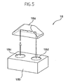
- the bill detecting sensor 18 is comprised of, for example, an optical type sensor, more specifically, a regression reflective photosensor, and as shown in FIG.5, formed of a prism 18a installed on the upper frame 2A side and a sensor body 18b installed on the lower frame 2B side.
- the prism 18a and sensor body 18b are arranged in such a manner that light emitted from a light-emitting portion 18c of the sensor body 18b is detected by a light-receiving portion 18d of the sensor body 18b thorough the prism 18a.
- the sensor 18 When a bill is passed through the bill feeding path 5 positioned between the prism 18a and sensor body 18b and the light is not detected in the light-receiving portion 18d, the sensor 18 generates a detection signal.
- the bill detecting sensor 18 may be comprised of a mechanical type sensor, as well as the optical type sensor.
- the bill reading means 20 for reading the bill information on the bill in a fed state.
- the bill reading means 20 is only required to have a configuration for irradiating the bill with the light to read the bill information when the bill is fed by the bill feeding mechanism 8, and generating a signal to enable the validity (authentication) of the bill to be judged, and in this embodiment, is configured to perform readout of the bill by applying the light from the opposite sides, and detecting the transmitted light and reflected light by a light-receiving device such as a photodiode or the like. Then, the optical signal on the read bill information undergoes photoelectric transformation, and is compared with the beforehand stored data of the authorized bill in the bill identifying means, and the authentication of the fed bill is thus judged.
- the shutter mechanism 50 On the downstream side of the bill insertion slot 6 is disposed the shutter mechanism 50 that blocks the bill insertion slot 6.
- the shutter mechanism 50 is configured to be normally in a state for opening the bill insertion slot 6, closed when a bill is inserted and the bill detecting sensor 18 detects a rear end of the bill (the bill detecting sensor 18 is OFF), and thus prevent fraud and the like.
- the shutter mechanism 50 has the rotating pieces 52 that are rotatably driven to appear at predetermined intervals in the direction perpendicular to the bill feeding direction in the bill feeding path 5, and a solenoid (pull-type) 54 that is a driving source that rotatably drives the rotating pieces 52.
- the rotating pieces 52 are installed in two locations in the width direction of a spindle 55, and long holes 5c extending in the bill feeding direction are formed in the bill feeding face 3a of the lower frame 2B constituting the bill feeding path 5 to cause respective rotating pieces 52 to appear.
- a bill passage detecting sensor 60 that detects passage of the bill.
- the bill passage detecting sensor 60 is to generate a detection signal when the bill judged as being valid is further fed to the downstream side, and the sensor 60 detects the rear end of the bill.
- the energization of the solenoid 54 is released (the solenoid is OFF), and the driving shaft 54a moves in the protruding direction by the biasing force of the biasing spring provided in the driving shaft 54a.
- the rotating pieces 52 constituting the shutter mechanism are rotatably driven to open the bill feeding path via the spindle 55 synchronized with the driving shaft 54a.
- the bill passage detecting sensor 60 is, as in the bill detecting sensor 18, comprised of an optical type sensor (regression reflective photosensor), and formed of a prism 60a installed on the upper frame 2A side and a sensor body 60b installed on the lower frame 2B side.
- the bill passage detecting sensor 60 may be comprised of a mechanical type sensor, as well as the optical type sensor.
- an informing device that informs that the bill is being inserted in a visible manner.
- Such an informing device can be comprised of, for example, an LED 70 that blinks, is lit when a user inserts a bill in the bill insertion slot 6, and informs the user of the bill being handled. It is thereby possible to prevent the user from erroneously inserting a next bill.
- FIGs.2, 3 and 6, described below is the configuration of the bill reading means 20 installed in the upper frame 2A and lower frame 2B.
- the bill reading means 20 has a light-emitting unit 24 provided with a first light-emitting portion 23 that is disposed on the upper frame 2A side and that is capable of emitting slit-shaped light over the feeding path width direction on the upper side of the fed bill, and a line sensor 25 disposed on the lower frame 2B side.
- the line sensor 25 installed on the lower frame 2B side has a light-receiving portion 26 disposed opposite to the first light-emitting portion 23 in a manner of sandwiching the bill, and second light-emitting portions 27 that are disposed adjacent to opposite sides of the light-receiving portion 26 on the bill feeding direction and that are capable of emitting slit-shaped light.
- the first light-emitting portion 23 disposed opposite to the light-receiving portion 26 of the line sensor 25 functions as a light source for transmission.
- the first light-emitting portion 23 is formed as the so-called light guide member 23b made of a synthetic resin formed in the shape of a rectangle rod, and preferably, has functions of receiving emitted light from the light-emitting device 23a such as an LED and the like installed at the end portion, and emitting the light while guiding the light along the longitudinal direction.
- the light-receiving portion 26 of the line sensor 25 is disposed in the shape of a line in parallel with the first light-emitting portion 23 that is the light guide member, and formed in the shape of a thin plate which extends in the direction of intersecting the bill feeding path 5, and which is formed in the shape of a band having a width to the extent of not affecting the sensitivity of a light-receiving sensor, not shown, provided in the light-receiving portion 26.
- the portion 26 has a configuration where a plurality of CCDs (Charge Coupled Device) is provided in the shape of a line in the center in the thickness direction of the light-receiving portion 26, and a Selfoc lens array 26a is arranged in the shape of a line in a position above the CCDs to gather the transmitted light and reflected light.
- CCDs Charge Coupled Device
- the second light-emitting portions 27 of the line sensor 25 function as light sources for reflection.
- each of the second light-emitting portions 27 is formed, as in the first light-emitting portion 23, as the so-called light guide member 27b made of a synthetic resin formed in the shape of a rectangle rod, and preferably, has functions of receiving emitted light from the light-emitting device 27a such as an LED and the like installed at the end portion, and emitting the light while guiding the light along the longitudinal direction.
- the light-emitting device 27a such as an LED and the like installed at the end portion
- each of the second light-emitting portions 27 is capable of applying the light to the bill at an elevation angle of 45 degrees, and is disposed so that the reflected light from the bill is received in the light-receiving portion 26 (light-receiving sensor) .
- the light emitted from the second light-emitting portion 27 is input to the light-receiving portion 26 at an angle of 45 degrees, but the incident angle is not limited to 45 degrees, and can be set as appropriate in ranges capable of reliably receiving the reflectedlight. Therefore, an arrangement of the second light-emitting portions 27 and second light-receiving portion 26 can be modified in design as appropriate corresponding to the configuration of the bill handling apparatus.
- the second light-emitting portions 27 are installed on the opposite sides with the light-receiving portion 26 sandwiched therebetween to emit the light from the opposite sides respectively at an angle of 45 degrees. This is because when a tear, crease and the like are present on the bill surface and the light is applied to a concavo-convex portion caused by a portion of the tear, crease or the like from only one side, a shaded area may be caused in the concavo-convex portion by shielding the light. Therefore, by emitting the light from the opposite sides, it is possible to prevent the concavo-convex portion from being darkened, and to obtain image data with higher accuracy than in emission from one side. Naturally, the second light-emitting portion 27 may be configured to be installed on only one side.
- the line sensor 25 is exposed to the bill feeding path 5, and is thereby provided with concavo-convex portions 25a, as shown in FIG.2, on opposite ends of its surface portion (that is substantially the same plane as the feeding face 3a) in the bill feeding direction to catch the fed bill hardly. Further, as in the line sensor 25, the light emitting unit 24 is provided with concavo-convex portions 24a, as shown in FIG.2, on opposite ends of its surface portion in the bill feeding direction to catch the fed bill hardly.
- the second light-emitting portion 27 (hereinafter, also referred to as the light guide member 27) formed as a light guide member of the line sensor 25 is installed to enter inside the side wall portion 3b.
- the light guide member 27 entering the side wall portion 3b is that an end portion (preferably opposite end portions) of the light guide member 27 extending in the width direction of the bill feeding path is only required to be positioned outward in the width direction from the side wall portion 3b forming the frame 2, and more specifically, to be preferably installed in a position more outward in the width direction than an inner face 3b' defining the side wall portion 3b.
- the inner faces 3b' are defined by regulating wall faces that regulate the opposite sides of the fed bill when the bill feeding path 5 is viewed in a plan view as in FIG.3.
- the emission amount of the light guide member For a length by which the end portion of the light guide member 27 enters the side wall potion 3b, it is preferable to consider the emission amount of the light guide member. In other words, generally, in a light guide member for coupling light from one end side and emitting the propagated light, there is a tendency that the emission amounts decrease at the opposite end portions. Therefore, the opposite end portions that are such regions where the emission amounts decrease are made positioned inside the side wall portions 3b, and it is thus possible to improve the bill reading accuracy by using the area where the emission amount is adequate.
- an opening 3D in the side wall portion 3b constituting the frame so that the line sensor 25 slides into the opening and is capable of being installed inside.
- This opening 3D is configured in a similar shape to that of the side face portion of the line sensor 25, and as shown in FIG.7, is formed in a substantially convex shape.
- the line sensor 25 is provided with the light guide member 27 extending in the width direction and the light-receiving portion 26, and is mounted on a sensor board 25A installed with a circuit for causing the light guide member 27 to emit light, a detecting circuit that detects the light incident upon the CCDs provided in line-shape to constitute the light receiving portion 26, an amplifier that amplifies an output of the detection circuit, an A/D converter that converts the amplified output signal into a digital signal, a control section to control these kinds of devices, and the like.
- the sensor board 25A is attached to a hold frame 25b in the shape of a substantially rectangle. Then, the hold frame 25B for holding the line sensor 25 and sensor board 25A is formed in a substantially convex portion as viewed from the side, and the opening 3D is configured in the shape corresponding to such a shape.
- the line sensor 25 is slid and installed in a predetermined position of the lower frame 2b, together with the hold frame 25B, through the opening 3D, as shown by the arrow in FIG. 8. More specifically, the line sensor 25 and sensor board 25A slid and inserted through the opening 3D formed in the lower frame 2B are fixed to predetermined positions in the lower frame 2B by screwing screws 80 into screw holes respectively formed in four corner portions of the hold frame 25B.
- the opening 3D is formed in the lower frame 2B constituting the apparatus body, and the line sensor 25 is slid and attached through the opening portion, it is possible to shorten the length of the entire apparatus in the bill feeding path width direction, and to install the line sensor 25 without decreasing the strength of the side wall portion 3b.
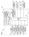
- FIG.9 is a block diagram illustrating a schematic configuration of the control means for controlling the bill handling apparatus 1 provided with the bill feeding mechanism 8, bill reading means 20, shutter mechanism 50 and the like.
- the control means 30 is provided with a control circuit board 100 for controlling the operation of each driving apparatus as described above.
- a CPU Central Processing Unit
- ROM Read Only Memory
- RAM Random Access Memory
- the ROM 112 stores operation programs for driving apparatuses such as the driving motor 10, solenoid 54, LED 70 and the like, various kinds of programs such as an authentication judgment program and the like, and permanently data.
- the CPU 110 operates according to the programs stored in the ROM 112, inputs and outputs signals to/from the driving apparatuses as described above via an I/O port 120, and controls the operation of the bill handling apparatus.
- the CPU 110 is connected to a driving motor driving circuit 125 (driving motor 10), solenoid 54, and LED 70 via the I/O port 120.
- the driving apparatuses are controlled in operation by control signals from the CPU 110 according to the operation programs stored in the ROM 112.
- the CPU 110 receives a detection signal from the bill detecting sensor 18, and a detection signal from the bill passage detecting sensor 60 via the I/O port 120, and based on these detection signals, controls forward/reverse driving of the driving motor 10, blinking of the LED 70, and driving of the solenoid 54.
- the RAM 114 stores the data and programs used for the CPU 110 to operate, and acquires the received light data of a bill targeted for judgment to temporarily store.
- the data is compared with the reference data stored in the reference data storage section 116, and the authentication judgment processing is thereby performed.
- the reference data is stored in the dedicated reference data storage section 116, but may be stored in the ROM 112.
- the reference data of the genuine bill may be stored beforehand in the reference data storage section 116, for example, the genuine bill is fed through the bill feeding mechanism 8 to acquire the received light data, and the data may be stored as the reference data.
- the CPU 110 is connected to the first light-emitting portion (light guide member) 23 in the light-emitting unit 24, and the light-receiving portion 26 and second light-emitting portions (light guide members) 27 in the line sensor 25 via the I/O port 120. These portions constitute a bill authentication judgment section 150 together with the CPU 110, ROM 112, RAM 114 and reference data storage section 116, and control the operations required fro the authentication judgment in the bill handling apparatus 1.
- the CPU 110 is connected to a control section of the game media lending apparatus into which the bill handling apparatus 1 is incorporated, and an upper apparatus 200 such as a host computer and the like of an external apparatus, via the I/O port 120, and transmits various kinds of signals (such as information of the bill, alarm signal and the like) to the upper apparatus.
- an upper apparatus 200 such as a host computer and the like of an external apparatus
- the driving motor 10 when the bill detecting sensor 18 detects insertion of a bill and becomes ON, the driving motor 10 is forward driven, and the LED 70 is lit.
- the feeding roller pairs 12, 13 and 14 are thereby driven to rotate in the bill insertion direction to feed the bill inside the apparatus, and the user is notified of the bill being handled to prevent insertion of an additional bill.
- the bill is fed inside the apparatus, the bill reading means 20 thereby reads the information, and the control means 30 executes the authentication judgment processing.
- the solenoid 54 is energized, and the rotating pieces 52 are thereby driven to rotate and block the bill insertion slot 6.
- the bill is further fed to the downstream side.
- the processing for causing the bill to temporarily wait may be performed.
- the driving of the driving motor 10 is halted. With the halt, the driving of the solenoid 54 is made OFF (energization is canceled) to withdraw the rotating pieces 52 from the bill feeding path 5, the bill insertion opening 6 is opened, and the LED 70 is extinguished.
- the processing for driving the driving motor 10 reversely is executed in this stage, the shutter mechanism 50 is opened, and the bill is sent back toward the bill insertion opening side.
- this send-back processing in the stage where the rear end of the bill is detecting by the bill detecting sensor 18, the LED 70 is extinguished.
- the light-emitting portion 27 provided in the line sensor 25 in the bill reading means 20 is configured as a light guide member, and emits the entire width direction of the fed bill, and it is thereby possible to improve the identification accuracy.
- the light guide member 27 has the configuration where light is input from the light-emitting device 27a such as an LED and the like, and applied to the bill being fed, and the cost is thereby reduced as compared with the configuration where a plurality of LEDs or the like is arranged.
- the light guide member 27 is installed to enter inside at its opposite ends the side wall portions 3b of the frame constituting the apparatus body, and the entire apparatus is thereby made compact. Further, in the light guide member 27, since the opposite ends where emission amounts generally decrease enter the side wall portions 3b, it is possible to avoid regions where the bill identification accuracy is unstable, and to improve the bill identification accuracy.
- the light-emitting device 27a is installed in the end portion of the light guide member 27, and thus enters the side wall portion 3b, and the entire apparatus is thereby made compact as compared with the configuration, for example, where a plurality of LEDs is arranged to form a light-emitting portion.
- the notch concave portions 3d are formed in the side wall portions 3b to position the end portions of the light guide member 27. As shown in FIG.2, the notch concave portions 3d are formed to expose the bill feeding face 3a on the lower frame 2B side, and configured so that the end portions of the light guide member 27 are positioned in the notch portions. Further, when the upper frame 2A is put on the lower frame 2B to close, the opposite end portions of the light-emitting unit 24 provided with the light-guide member 23 provided on the upper frame 2Aside are positioned inside the notch concave portions 3d, and it is thereby possible to reduce the size not only in the width direction of the bill feeding path but also in the thickness direction.
- the opposite end portions of the light guide member 23 provided in the light-emitting unit 24 are also are positioned inside the notch concave portions 3d as in the light guide member 27, it is possible to miniaturize in the width direction of the bill feeding path, while since the end portions where the emission amounts decrease are positioned in the notch concave portions formed in the side wall portions 3b, it is possible to avoid regions where the bill identification accuracy is unstable, and to improve the bill identification accuracy.
- a light-emitting portion constituting the bill reading means is a light guide member, and that the light guide member is installed to be positioned inside the side wall portions of the frame, and the other configurations are capable of being modified as appropriate.
- the configuration and arrangement pattern of the reading means (sensor) for reading a bill, method of reading the bill, method of performing the bill authentication judgment processing and the like are not limited to the above-mentioned embodiment, and are capable of being carried into practice with various modifications thereof.
- the bill handling apparatus of the invention is capable of being incorporated into various kinds of apparatuses that provide products and/or service by inserting a bill, while being not limited to a game media lending apparatus. Further, this embodiment describes the apparatus for handling bills as an example, but the invention is applicable to apparatuses for making an authentication judgment on gold certificates, securities and the like.
Landscapes
- Health & Medical Sciences (AREA)
- General Health & Medical Sciences (AREA)
- Toxicology (AREA)
- Physics & Mathematics (AREA)
- General Physics & Mathematics (AREA)
- Inspection Of Paper Currency And Valuable Securities (AREA)
- Vending Machines For Individual Products (AREA)
Abstract
Description
- The present invention relates to a bill handling apparatus for feeding a bill inserted from a bill insertion slot, while reading the fed bill to identify the validity.
- Generally, a bill handling apparatus identifies the validity of a bill inserted from a bill insertion slot by a user, and is incorporated into service apparatuses that provides various kinds of products and service corresponding to the bill value judged as being valid, such as, for example, a game media lending machine installed in a game hole, or an automatic dispenser, ticket-vending machine and the like installed in public areas.
- The bill handling apparatus is usually provided with operation devices such as a bill feeding mechanism that feeds a bill inserted into a bill insertion slot, bill reading means for executing readout of the fed bill, bill identifying means for identifying the validity (also referred to as authentication judgment) from the read bill information and the like, and control means for driving and controlling the operation devices.
- The above-mentioned bill reading means is provided with a photosensor which applies light to the fed bill and detects the reflected light and/or transmitted light, and the bill identifying means compares a detection signal from the photosensor with beforehand stored authorized bill data to identify the validity. In this case, as disclosed in
Japanese Laid-Open Patent Publication No. 2001-357429 No. 2001-357429 - Then, the light-emitting portion that irradiates in the shape of a slit is comprised of a light guide member that extends in the width direction of the fed bill and that receives at its one end the light applied from at least one LED, such a light guide member and light-receiving portion are disposed opposite to each other with a bill feeding path positioned therebetween, or disposed in parallel with each other on one side of the bill feeding path, and readout of the bill information is thereby executed.
- As described above, in the configuration where the light of the LED that is an emitter is applied to the light guide member, due to characteristics of the light guide member, there is a problem that emission amounts are unstable at its one end and the other end. Therefore, in the case of using, as an irradiation portion, a predetermined length from the center portion where the emission amount of the light guide member is stable to opposite end portions, it is necessary to dispose the opposite end portions of the light guide member to exceed the passage width of the bill, and a problem arises that the bill identifying apparatus is increased in size in the bill passage width direction.
- Accordingly, a bill handling apparatus enabling its miniaturization is required.
- To achieve the above-mentioned object, a bill handling apparatus according to the present invention is characterized by comprising a frame provided with a bill feeding path in which a bill is fed and with a side wall portion provided in a width direction of the bill feeding path, a bill reading section installed in the frame to read a fed bill, and a bill identifying section for identifying authentication of the bill read by the bill reading section, where the bill reading section is provided with a light guide member to which light is input from a light-emitting device as a light-emitting portion that applies the light to the fed bill, and the light guide member is installed to enter inside the side wall portion.
- Additional obj ects and advantages of the invention will be set forth in the description which follows, and in part will be obvious from the description, or may be learned by practice of the invention. The objects and advantages of the invention may be realized and obtained by means of the instrumentalities and combinations particularly pointed out hereinafter.
- The accompanying drawings, which are incorporated in and constitute a part of the specification, illustrate embodiments of the invention, and together with the general description given above and the detailed description of the embodiments given below, serve to explain the principles of the invention.
- FIG.1 is a perspective view showing an entire configuration of one embodiment of a bill handling apparatus according to the invention;
- FIG.2 is a perspective view showing a state where an upper frame is opened with respect to a lower frame;
- FIG.3 is a plan view showing a bill feeding path portion of the lower frame;
- FIG. 4 is a rear elevational view of the lower frame;
- FIG.5 is a perspective view showing a configuration of a bill detecting sensor;
- FIG.6 is a view schematically showing the configuration of the bill handling apparatus;
- FIG. 7 is a side elevational view of the bill handling apparatus;
- FIG.8 is another rear elevational view of the lower frame, showing a state where a control board is removed; and
- FIG.9 is a block diagram illustrating a control system of the bill handling apparatus.
- An embodiment of the invention will be described below with reference to accompanying drawings.
- FIGs.1 to 4 are views showing a configuration of a bill handling apparatus according to this embodiment, FIG.1 is a perspective view showing an entire configuration, FIG.2 is a perspective view showing a state where an upper frame is opened with respect to a lower frame, FIG.3 is a plan view showing a bill feeding path portion of the lower frame, and FIG.4 is a rear elevational view of the lower frame.
- A
bill handling apparatus 1 of this embodiment is configured to be capable of being incorporated into a game media lending apparatus (not shown) installed among various kinds of game machines such as, for example, slot machines and the like. In this case, the game media lending apparatus may be provided with another apparatus (for example, a bill storage unit, coin identifying apparatus, storage media processing apparatus, power supply apparatus and the like) on the upper or lower side of thebill handling apparatus 1, and thebill handling apparatus 1 may be formed integrally with the other apparatus, or formed separately. Then, when a bill is inserted in such abill handling apparatus 1 and the validity of the inserted bill is judged, the processing corresponding to the bill value is performed such as the processing for lending game media, the processing of writing in a storage medium such as a prepaid card, or like. - The
bill handling apparatus 1 is provided with aframe 2 formed in the shape of a substantially cuboid, and theframe 2 is mounted to a locking portion of the game media lending apparatus not shown in the figure. Theframe 2 has alower frame 2B as a base side and an upper frame 2Aopenable/closable with respect to thelower frame 2B to cover thelower frame 2B. Theframes - The
lower frame 2B has the shape of a substantially cuboid, and is provided with abill feeding face 3a for feeding a bill, andside wall portions 3b formed on the opposite sides of thebill feeding face 3a. Meanwhile, theupper frame 2A is configured in the shape of a plate provided with abill feeding face 3c, and when theupper frame 2A is closed to enter between theside wall portions 3b on the opposite sides of thelower frame 2B, a clearance (bill feeding path) 5 to feed a bill is formed between opposite portions of thebill feeding face 3a andbill feeding face 3c. - Then, the
upper frame 2A andlower frame 2B are respectively provided withbill insertion portions bill feeding path 5. Thesebill insertion portions bill insertion slot 6 in the shape of a slit when theupper frame 2A andlower frame 2B are closed, and as shown in FIG.1, a bill M is inserted inside from a shorter side of the bill along the direction of allow A. - Further, a
lock shaft 4 capable of locking in thelower frame 2B is disposed on the front end side of theupper frame 2A. Thelock shaft 4 is provided with anoperation portion 4a, and by operating theoperation portion 4a to rotate against the biasing force of a biasingspring 4b, rotates on a pivot P as a center to release the lock state of theupper frame 2A andlower frame 2B (the state where the frames are closed: overlapping state). - In the
lower frame 2B are provided abill feeding mechanism 8, abill detecting sensor 18 that detects a bill inserted in thebill insertion slot 6, bill reading means(a bill reading section) 20 that is installed on the downstream side of thebill detecting sensor 18 and that reads information of the bill in a fed state, ashutter mechanism 50 that is installed in thebill feeding path 5 between thebill insertion slot 6 and thebill detecting sensor 18 and that is driven to block thebill insertion slot 6, and control means (circuit control board(a bill identifying section)) 100 for controlling driving of structural members such as the aforementionedbill feeding mechanism 8, bill reading means 20,shutter mechanism 50 and the like, while identifying (performing authentication judgment processing) the validity of the read bill. - The
bill feeding mechanism 8 is a mechanism capable of feeding the bill inserted from thebill insertion slot 6 along the insertion direction A, while feeding back the bill in an insertion state toward thebill insertion slot 6. Thebill feeding mechanism 8 is provided with a drivingmotor 10 that is a driving source installed on thelower frame 2B side, andfeeding roller pairs motor 10 and disposed in thebill feeding path 5 at predetermined intervals along the bill feeding direction. - The
feeding roller pair 12 is provided withdriving rollers 12A disposed on thelower frame 2B side, andpinch rollers 12B disposed on theupper frame 2A side to come into contact with thedriving roller 12A. Thesedriving rollers 12A andpinch rollers 12B are installed in two respective locations at predetermined intervals along the direction perpendicular to the bill feeding direction. Thesedriving rollers 12A andpinch rollers 12B are exposed at their parts to thebill feeding path 5. - The
driving rollers 12A installed in two respective positions are fixed to a drivingshaft 12a rotatably supported by thelower frame 2B, and the twopinch rollers 12B are rotatably supported by aspindle 12b supported by theupper frame 2A. In this case, abiasing member 12c for biasing thespindle 12b to the drivingshaft 12a side is provided in theupper frame 2A, and brings thepinch rollers 12B into contact with thedriving roller side 12A by predetermined pressure. - In addition, as in the
roller pair 12, thefeeding roller pairs driving rollers shafts pinch rollers spindles pinch rollers driving rollers members 13c, 14c, respectively. - The feeding roller pairs 12, 13 and 14 are driven in synchronization with one another by a driving
force conveying mechanism 15 coupled to the drivingmotor 10. The drivingforce conveying mechanism 15 is comprised of a gear train disposed rotatably on oneside wall portion 3b of thelower frame 2B. More specifically, themechanism 15 is formed of the gear train having anoutput gear 10a fixed to an output shaft of thedriving motor 10,input gears output gear 10a and mounted on the end portions of thedriving shafts idle gears 16 installed between the gears. - According to the above-mentioned configuration, when the driving
motor 10 is driven forward, each of thefeeding roller pairs motor 10 is driven reversely, being driven reversely to send the bill back to the bill insertion slot side. - The
bill detecting sensor 18 is to generate a detection signal in detecting a bill inserted in thebill insertion slot 6, and in this embodiment, is installed between rotating pieces constituting the shutter mechanism described later, and the bill reading means 20 for reading the bill. Thebill detecting sensor 18 is comprised of, for example, an optical type sensor, more specifically, a regression reflective photosensor, and as shown in FIG.5, formed of aprism 18a installed on theupper frame 2A side and asensor body 18b installed on thelower frame 2B side. More specifically, theprism 18a andsensor body 18b are arranged in such a manner that light emitted from a light-emitting portion 18c of thesensor body 18b is detected by a light-receivingportion 18d of thesensor body 18b thorough theprism 18a. When a bill is passed through thebill feeding path 5 positioned between theprism 18a andsensor body 18b and the light is not detected in the light-receivingportion 18d, thesensor 18 generates a detection signal. - In addition, the
bill detecting sensor 18 may be comprised of a mechanical type sensor, as well as the optical type sensor. - On the downstream side of the
bill detecting sensor 18 is installed the bill reading means 20 for reading the bill information on the bill in a fed state. The bill reading means 20 is only required to have a configuration for irradiating the bill with the light to read the bill information when the bill is fed by thebill feeding mechanism 8, and generating a signal to enable the validity (authentication) of the bill to be judged, and in this embodiment, is configured to perform readout of the bill by applying the light from the opposite sides, and detecting the transmitted light and reflected light by a light-receiving device such as a photodiode or the like. Then, the optical signal on the read bill information undergoes photoelectric transformation, and is compared with the beforehand stored data of the authorized bill in the bill identifying means, and the authentication of the fed bill is thus judged. - On the downstream side of the
bill insertion slot 6 is disposed theshutter mechanism 50 that blocks thebill insertion slot 6. Theshutter mechanism 50 is configured to be normally in a state for opening thebill insertion slot 6, closed when a bill is inserted and thebill detecting sensor 18 detects a rear end of the bill (thebill detecting sensor 18 is OFF), and thus prevent fraud and the like. - More specifically, the
shutter mechanism 50 has the rotatingpieces 52 that are rotatably driven to appear at predetermined intervals in the direction perpendicular to the bill feeding direction in thebill feeding path 5, and a solenoid (pull-type) 54 that is a driving source that rotatably drives therotating pieces 52. In this case, the rotatingpieces 52 are installed in two locations in the width direction of aspindle 55, andlong holes 5c extending in the bill feeding direction are formed in thebill feeding face 3a of thelower frame 2B constituting thebill feeding path 5 to cause respectiverotating pieces 52 to appear. - Further, on the downstream side of the bill reading means 20 is provided a bill
passage detecting sensor 60 that detects passage of the bill. The billpassage detecting sensor 60 is to generate a detection signal when the bill judged as being valid is further fed to the downstream side, and thesensor 60 detects the rear end of the bill. Based on the occurrence f the detection signal, the energization of thesolenoid 54 is released (the solenoid is OFF), and the drivingshaft 54a moves in the protruding direction by the biasing force of the biasing spring provided in the drivingshaft 54a. By this means, the rotatingpieces 52 constituting the shutter mechanism are rotatably driven to open the bill feeding path via thespindle 55 synchronized with the drivingshaft 54a. - The bill
passage detecting sensor 60 is, as in thebill detecting sensor 18, comprised of an optical type sensor (regression reflective photosensor), and formed of aprism 60a installed on theupper frame 2A side and asensor body 60b installed on thelower frame 2B side. Naturally, the billpassage detecting sensor 60 may be comprised of a mechanical type sensor, as well as the optical type sensor. - In the vicinity of the
bill insertion slot 6 is provided an informing device that informs that the bill is being inserted in a visible manner. Such an informing device can be comprised of, for example, anLED 70 that blinks, is lit when a user inserts a bill in thebill insertion slot 6, and informs the user of the bill being handled. It is thereby possible to prevent the user from erroneously inserting a next bill. - Referring to FIGs.2, 3 and 6, described below is the configuration of the bill reading means 20 installed in the
upper frame 2A andlower frame 2B. - The bill reading means 20 has a light-emitting
unit 24 provided with a first light-emittingportion 23 that is disposed on theupper frame 2A side and that is capable of emitting slit-shaped light over the feeding path width direction on the upper side of the fed bill, and aline sensor 25 disposed on thelower frame 2B side. - The
line sensor 25 installed on thelower frame 2B side has a light-receivingportion 26 disposed opposite to the first light-emittingportion 23 in a manner of sandwiching the bill, and second light-emittingportions 27 that are disposed adjacent to opposite sides of the light-receivingportion 26 on the bill feeding direction and that are capable of emitting slit-shaped light. - The first light-emitting
portion 23 disposed opposite to the light-receivingportion 26 of theline sensor 25 functions as a light source for transmission. As shown in FIG.2, the first light-emittingportion 23 is formed as the so-calledlight guide member 23b made of a synthetic resin formed in the shape of a rectangle rod, and preferably, has functions of receiving emitted light from the light-emittingdevice 23a such as an LED and the like installed at the end portion, and emitting the light while guiding the light along the longitudinal direction. By this means, it is possible to apply the slit-shaped light uniformly to the entire region in the width direction of the feeding path of the fed bill with a simple configuration. - In addition, the light-receiving
portion 26 of theline sensor 25 is disposed in the shape of a line in parallel with the first light-emittingportion 23 that is the light guide member, and formed in the shape of a thin plate which extends in the direction of intersecting thebill feeding path 5, and which is formed in the shape of a band having a width to the extent of not affecting the sensitivity of a light-receiving sensor, not shown, provided in the light-receivingportion 26. More specifically, theportion 26 has a configuration where a plurality of CCDs (Charge Coupled Device) is provided in the shape of a line in the center in the thickness direction of the light-receivingportion 26, and aSelfoc lens array 26a is arranged in the shape of a line in a position above the CCDs to gather the transmitted light and reflected light. - The second light-emitting
portions 27 of theline sensor 25 function as light sources for reflection. As shown in FIG. 3, each of the second light-emittingportions 27 is formed, as in the first light-emittingportion 23, as the so-calledlight guide member 27b made of a synthetic resin formed in the shape of a rectangle rod, and preferably, has functions of receiving emitted light from the light-emittingdevice 27a such as an LED and the like installed at the end portion, and emitting the light while guiding the light along the longitudinal direction. By this means, it is possible to apply the slit-shaped light uniformly to the entire region in the width direction of the feeding path of the fed bill with a simple configuration. - In addition, each of the second light-emitting
portions 27 is capable of applying the light to the bill at an elevation angle of 45 degrees, and is disposed so that the reflected light from the bill is received in the light-receiving portion 26 (light-receiving sensor) . In this case, the light emitted from the second light-emittingportion 27 is input to the light-receivingportion 26 at an angle of 45 degrees, but the incident angle is not limited to 45 degrees, and can be set as appropriate in ranges capable of reliably receiving the reflectedlight. Therefore, an arrangement of the second light-emittingportions 27 and second light-receivingportion 26 can be modified in design as appropriate corresponding to the configuration of the bill handling apparatus. Further, the second light-emittingportions 27 are installed on the opposite sides with the light-receivingportion 26 sandwiched therebetween to emit the light from the opposite sides respectively at an angle of 45 degrees. This is because when a tear, crease and the like are present on the bill surface and the light is applied to a concavo-convex portion caused by a portion of the tear, crease or the like from only one side, a shaded area may be caused in the concavo-convex portion by shielding the light. Therefore, by emitting the light from the opposite sides, it is possible to prevent the concavo-convex portion from being darkened, and to obtain image data with higher accuracy than in emission from one side. Naturally, the second light-emittingportion 27 may be configured to be installed on only one side. - The
line sensor 25 is exposed to thebill feeding path 5, and is thereby provided with concavo-convex portions 25a, as shown in FIG.2, on opposite ends of its surface portion (that is substantially the same plane as thefeeding face 3a) in the bill feeding direction to catch the fed bill hardly. Further, as in theline sensor 25, thelight emitting unit 24 is provided with concavo-convex portions 24a, as shown in FIG.2, on opposite ends of its surface portion in the bill feeding direction to catch the fed bill hardly. - The second light-emitting portion 27 (hereinafter, also referred to as the light guide member 27) formed as a light guide member of the
line sensor 25 is installed to enter inside theside wall portion 3b. In this case, as shown in FIG.3, thelight guide member 27 entering theside wall portion 3b is that an end portion (preferably opposite end portions) of thelight guide member 27 extending in the width direction of the bill feeding path is only required to be positioned outward in the width direction from theside wall portion 3b forming theframe 2, and more specifically, to be preferably installed in a position more outward in the width direction than aninner face 3b' defining theside wall portion 3b. In addition, theinner faces 3b' are defined by regulating wall faces that regulate the opposite sides of the fed bill when thebill feeding path 5 is viewed in a plan view as in FIG.3. - For a length by which the end portion of the
light guide member 27 enters theside wall potion 3b, it is preferable to consider the emission amount of the light guide member. In other words, generally, in a light guide member for coupling light from one end side and emitting the propagated light, there is a tendency that the emission amounts decrease at the opposite end portions. Therefore, the opposite end portions that are such regions where the emission amounts decrease are made positioned inside theside wall portions 3b, and it is thus possible to improve the bill reading accuracy by using the area where the emission amount is adequate. - Further, in the above-mentioned configuration, it is preferable forming an
opening 3D in theside wall portion 3b constituting the frame so that theline sensor 25 slides into the opening and is capable of being installed inside. Thisopening 3D is configured in a similar shape to that of the side face portion of theline sensor 25, and as shown in FIG.7, is formed in a substantially convex shape. In other words, theline sensor 25 is provided with thelight guide member 27 extending in the width direction and the light-receivingportion 26, and is mounted on asensor board 25A installed with a circuit for causing thelight guide member 27 to emit light, a detecting circuit that detects the light incident upon the CCDs provided in line-shape to constitute thelight receiving portion 26, an amplifier that amplifies an output of the detection circuit, an A/D converter that converts the amplified output signal into a digital signal, a control section to control these kinds of devices, and the like. Thesensor board 25A is attached to a hold frame 25b in the shape of a substantially rectangle. Then, thehold frame 25B for holding theline sensor 25 andsensor board 25A is formed in a substantially convex portion as viewed from the side, and theopening 3D is configured in the shape corresponding to such a shape. - The
line sensor 25 is slid and installed in a predetermined position of the lower frame 2b, together with thehold frame 25B, through theopening 3D, as shown by the arrow in FIG. 8. More specifically, theline sensor 25 andsensor board 25A slid and inserted through theopening 3D formed in thelower frame 2B are fixed to predetermined positions in thelower frame 2B by screwingscrews 80 into screw holes respectively formed in four corner portions of thehold frame 25B. - Thus, according to the configuration where the
opening 3D is formed in thelower frame 2B constituting the apparatus body, and theline sensor 25 is slid and attached through the opening portion, it is possible to shorten the length of the entire apparatus in the bill feeding path width direction, and to install theline sensor 25 without decreasing the strength of theside wall portion 3b. - FIG.9 is a block diagram illustrating a schematic configuration of the control means for controlling the
bill handling apparatus 1 provided with thebill feeding mechanism 8, bill reading means 20,shutter mechanism 50 and the like. - The control means 30 is provided with a
control circuit board 100 for controlling the operation of each driving apparatus as described above. On thecontrol circuit board 100 are mounted a CPU (Central Processing Unit) 110 constituting the bill identifying means, ROM (Read Only Memory) 112, RAM (Random Access Memory) 114 and a referencedata storage section 116. - The
ROM 112 stores operation programs for driving apparatuses such as the drivingmotor 10,solenoid 54,LED 70 and the like, various kinds of programs such as an authentication judgment program and the like, and permanently data. TheCPU 110 operates according to the programs stored in theROM 112, inputs and outputs signals to/from the driving apparatuses as described above via an I/O port 120, and controls the operation of the bill handling apparatus. In other words, theCPU 110 is connected to a driving motor driving circuit 125 (driving motor 10),solenoid 54, andLED 70 via the I/O port 120. The driving apparatuses are controlled in operation by control signals from theCPU 110 according to the operation programs stored in theROM 112. Further, theCPU 110 receives a detection signal from thebill detecting sensor 18, and a detection signal from the billpassage detecting sensor 60 via the I/O port 120, and based on these detection signals, controls forward/reverse driving of the drivingmotor 10, blinking of theLED 70, and driving of thesolenoid 54. - The
RAM 114 stores the data and programs used for theCPU 110 to operate, and acquires the received light data of a bill targeted for judgment to temporarily store. The data is compared with the reference data stored in the referencedata storage section 116, and the authentication judgment processing is thereby performed. In addition, in this embodiment, the reference data is stored in the dedicated referencedata storage section 116, but may be stored in theROM 112. Further, although the reference data of the genuine bill may be stored beforehand in the referencedata storage section 116, for example, the genuine bill is fed through thebill feeding mechanism 8 to acquire the received light data, and the data may be stored as the reference data. - Further, the
CPU 110 is connected to the first light-emitting portion (light guide member) 23 in the light-emittingunit 24, and the light-receivingportion 26 and second light-emitting portions (light guide members) 27 in theline sensor 25 via the I/O port 120. These portions constitute a billauthentication judgment section 150 together with theCPU 110,ROM 112,RAM 114 and referencedata storage section 116, and control the operations required fro the authentication judgment in thebill handling apparatus 1. - Furthermore, the
CPU 110 is connected to a control section of the game media lending apparatus into which thebill handling apparatus 1 is incorporated, and anupper apparatus 200 such as a host computer and the like of an external apparatus, via the I/O port 120, and transmits various kinds of signals (such as information of the bill, alarm signal and the like) to the upper apparatus. - According to the bill handling apparatus configured as described above, when the
bill detecting sensor 18 detects insertion of a bill and becomes ON, the drivingmotor 10 is forward driven, and theLED 70 is lit. The feeding roller pairs 12, 13 and 14 are thereby driven to rotate in the bill insertion direction to feed the bill inside the apparatus, and the user is notified of the bill being handled to prevent insertion of an additional bill. - The bill is fed inside the apparatus, the bill reading means 20 thereby reads the information, and the control means 30 executes the authentication judgment processing. At this point, in this embodiment, when the
bill detecting sensor 18 detects the rear end of the bill (thebill detecting sensor 18 is OFF), thesolenoid 54 is energized, and therotating pieces 52 are thereby driven to rotate and block thebill insertion slot 6. - When the bill is judged as being genuine in the above-mentioned authentication judgment processing, the bill is further fed to the downstream side. At this point, to be able to support money-back processing and the like that would occur due to some reason, the processing for causing the bill to temporarily wait may be performed. Then, in the stage where the rear end of the bill further fed to the downstream side is detected by the bill
passage detecting sensor 60, the driving of the drivingmotor 10 is halted. With the halt, the driving of thesolenoid 54 is made OFF (energization is canceled) to withdraw therotating pieces 52 from thebill feeding path 5, thebill insertion opening 6 is opened, and theLED 70 is extinguished. - In addition, when the bill is judged being not genuine in the above-mentioned authentication judgment processing, the processing for driving the driving
motor 10 reversely is executed in this stage, theshutter mechanism 50 is opened, and the bill is sent back toward the bill insertion opening side. In this send-back processing, in the stage where the rear end of the bill is detecting by thebill detecting sensor 18, theLED 70 is extinguished. - In the
bill handling apparatus 1 configured as described above, the light-emittingportion 27 provided in theline sensor 25 in the bill reading means 20 is configured as a light guide member, and emits the entire width direction of the fed bill, and it is thereby possible to improve the identification accuracy. Further, thelight guide member 27 has the configuration where light is input from the light-emittingdevice 27a such as an LED and the like, and applied to the bill being fed, and the cost is thereby reduced as compared with the configuration where a plurality of LEDs or the like is arranged. Further, as shown in FIG.3, thelight guide member 27 is installed to enter inside at its opposite ends theside wall portions 3b of the frame constituting the apparatus body, and the entire apparatus is thereby made compact. Further, in thelight guide member 27, since the opposite ends where emission amounts generally decrease enter theside wall portions 3b, it is possible to avoid regions where the bill identification accuracy is unstable, and to improve the bill identification accuracy. - Further, as shown in FIG.3, the light-emitting
device 27a is installed in the end portion of thelight guide member 27, and thus enters theside wall portion 3b, and the entire apparatus is thereby made compact as compared with the configuration, for example, where a plurality of LEDs is arranged to form a light-emitting portion. - In addition, in the configuration of the frame of the apparatus body as described above, the notch
concave portions 3d are formed in theside wall portions 3b to position the end portions of thelight guide member 27. As shown in FIG.2, the notchconcave portions 3d are formed to expose thebill feeding face 3a on thelower frame 2B side, and configured so that the end portions of thelight guide member 27 are positioned in the notch portions. Further, when theupper frame 2A is put on thelower frame 2B to close, the opposite end portions of the light-emittingunit 24 provided with the light-guide member 23 provided on the upper frame 2Aside are positioned inside the notchconcave portions 3d, and it is thereby possible to reduce the size not only in the width direction of the bill feeding path but also in the thickness direction. Furthermore, since the opposite end portions of thelight guide member 23 provided in the light-emittingunit 24 are also are positioned inside the notchconcave portions 3d as in thelight guide member 27, it is possible to miniaturize in the width direction of the bill feeding path, while since the end portions where the emission amounts decrease are positioned in the notch concave portions formed in theside wall portions 3b, it is possible to avoid regions where the bill identification accuracy is unstable, and to improve the bill identification accuracy. - In the foregoing, the embodiment of the invention is described, but it is a feature of the invention that a light-emitting portion constituting the bill reading means is a light guide member, and that the light guide member is installed to be positioned inside the side wall portions of the frame, and the other configurations are capable of being modified as appropriate. For example, the configuration and arrangement pattern of the reading means (sensor) for reading a bill, method of reading the bill, method of performing the bill authentication judgment processing and the like are not limited to the above-mentioned embodiment, and are capable of being carried into practice with various modifications thereof.
- The bill handling apparatus of the invention is capable of being incorporated into various kinds of apparatuses that provide products and/or service by inserting a bill, while being not limited to a game media lending apparatus. Further, this embodiment describes the apparatus for handling bills as an example, but the invention is applicable to apparatuses for making an authentication judgment on gold certificates, securities and the like.
- Additional advantages and modifications will readily occur to those skilled in the art. Therefore, the invention in its broader aspects is not limited to the specific details and representative embodiments shown and described herein. Accordingly, various modifications may be made without departing from the spirit or scope of the general inventive concept as defined by the appended claims and their equivalents.
Claims (10)
- A bill handling apparatus (1) characterized by comprising:a frame (2) having a bill feeding path (5) in which a bill is fed, and a side wall portion (3b) provided in a width direction of the bill feeding path (5);a bill reading section (20), installed in the frame (2), for reading a fed bill; anda bill identifying section (100) for identifying authentication of the bill read by the bill reading section (20),wherein the bill reading section (20) has a light guide member (27b) to which light is input from a light-emitting device (27a), as a light-emitting portion (27) that applies the light to the fed bill, and
the light guide member (27b) is installed to enter inside the side wall portion (3b). - The bill handling apparatus (1) as claimed in claim 1, characterized in that the light-emitting device (27a) is installed at the end portion of the light guide member (27b).
- The bill handling apparatus (1) as claimed in claim 1 or claim 2, characterized in that the bill reading section (20) is provided with a line sensor (25) having the light guide member (27b), and
an opening (3D) is formed in the side wall portion (3b) to enable the line sensor (25) to be slid and installed. - The bill handling apparatus (1) as claimed in any one of the preceding claims, characterized in that a notch concave portion (3d) is formed in the side wall portion (3b) so that the end portion of the light guide member (27b) is positioned therein.
- The bill handling apparatus (1) as claimed in any one of the preceding claims, characterized in that the frame (2) has a lower frame (2B) with the side wall portion (3b) and an upper frame (2A) openable/closable with respect to the lower frame (2B) to cover the lower frame (2B), and
the bill reading section (20) has a light-emitting unit (24) provided with the light-emitting portion (23) that is disposed on the upper frame (2A) side for emitting slit-shaped light over the feeding path width direction on the upper side of the fed bill, and a line sensor (25) disposed on the lower frame (2B) side. - The bill handling apparatus (1) as claimed in claim 5, characterized in that the line sensor (25) has a light-receiving portion (26) disposed opposite to the light-emitting portion (23) of the light-emitting unit (24) in a manner of sandwiching the bill, and the light-emitting portions (27) that are disposed adjacent to opposite sides of the light-receiving portion (26) on the bill feeding direction for emitting slit-shaped light.
- The bill handling apparatus (1) as claimed in claim 6, characterized in that the light-emitting portions (27) of the line sensor (25) apply the light to the bill from the opposite sides of the light-receiving portion (26) respectively at an elevation angle of predetermined degrees, and are disposed so that the reflected light from the bill is received in the light-receiving portion (26) .
- The bill handling apparatus (1) as claimed in claim 3, characterized in that the line sensor (25) is provided with concavo-convex portions (25a) on opposite ends of its surface portion in the bill feeding direction to catch the fed bill hardly.
- The bill handling apparatus (1) as claimed in claim 6, characterized in that the opposite end portions of the light-emitting portions (27) of the line sensor (25) are positioned to enter inside the side wall portion (3b).
- The bill handling apparatus (1) as claimed in claim 5, characterized in that when the upper frame (2A) is put on the lower frame (2B) to close, the opposite end portions of the light-emitting portion (23) of the light-emitting unit (24) provided on the upper frame (2A) side are positioned to enter inside the side wall portion (3b).
Applications Claiming Priority (1)
| Application Number | Priority Date | Filing Date | Title |
|---|---|---|---|
| JP2006225749A JP4656658B2 (en) | 2006-08-22 | 2006-08-22 | Banknote handling equipment |
Publications (3)
| Publication Number | Publication Date |
|---|---|
| EP1892678A2 true EP1892678A2 (en) | 2008-02-27 |
| EP1892678A3 EP1892678A3 (en) | 2008-08-20 |
| EP1892678B1 EP1892678B1 (en) | 2011-11-23 |
Family
ID=38541984
Family Applications (1)
| Application Number | Title | Priority Date | Filing Date |
|---|---|---|---|
| EP07016278A Not-in-force EP1892678B1 (en) | 2006-08-22 | 2007-08-20 | Bill handling apparatus |
Country Status (7)
| Country | Link |
|---|---|
| US (1) | US8820508B2 (en) |
| EP (1) | EP1892678B1 (en) |
| JP (1) | JP4656658B2 (en) |
| CN (1) | CN101131774B (en) |
| AT (1) | ATE534981T1 (en) |
| AU (1) | AU2007209786B2 (en) |
| ZA (1) | ZA200707014B (en) |
Cited By (1)
| Publication number | Priority date | Publication date | Assignee | Title |
|---|---|---|---|---|
| CN102842168A (en) * | 2012-09-06 | 2012-12-26 | 上海古鳌电子科技股份有限公司 | Image processing device |
Families Citing this family (13)
| Publication number | Priority date | Publication date | Assignee | Title |
|---|---|---|---|---|
| JP4656658B2 (en) | 2006-08-22 | 2011-03-23 | 株式会社ユニバーサルエンターテインメント | Banknote handling equipment |
| JP4671932B2 (en) * | 2006-08-22 | 2011-04-20 | 株式会社ユニバーサルエンターテインメント | Banknote handling equipment |
| JP5210067B2 (en) * | 2008-07-22 | 2013-06-12 | 株式会社ユニバーサルエンターテインメント | Paper sheet processing equipment |
| JP5687913B2 (en) * | 2011-01-31 | 2015-03-25 | マミヤ・オーピー・ネクオス株式会社 | Card processing device with full detector of card stacker |
| JP5727283B2 (en) * | 2011-04-25 | 2015-06-03 | マミヤ・オーピー・ネクオス株式会社 | Card processing apparatus having a conveyance path opening structure |
| US9734648B2 (en) * | 2012-12-11 | 2017-08-15 | Ncr Corporation | Method of categorising defects in a media item |
| JP6042242B2 (en) * | 2013-03-15 | 2016-12-14 | 株式会社東芝 | Paper sheet transport device |
| JP5857078B2 (en) * | 2013-04-19 | 2016-02-10 | 株式会社ユニバーサルエンターテインメント | Paper sheet processing device and game medium lending device |
| JP6149500B2 (en) * | 2013-05-15 | 2017-06-21 | ウシオ電機株式会社 | Light guide and light source unit |
| JP6079534B2 (en) * | 2013-09-30 | 2017-02-15 | 沖電気工業株式会社 | Bill discrimination device |
| JP6515501B2 (en) * | 2014-11-20 | 2019-05-22 | 富士電機株式会社 | Paper sheet identification device |
| EP3721419B1 (en) * | 2017-12-07 | 2024-10-16 | Crane Payment Innovations, Inc. | Open banknote path system |
| JP2025070176A (en) * | 2023-10-19 | 2025-05-02 | 沖電気工業株式会社 | Media Processing Device |
Citations (1)
| Publication number | Priority date | Publication date | Assignee | Title |
|---|---|---|---|---|
| WO1996023282A1 (en) | 1995-01-23 | 1996-08-01 | Mars Incorporated | Molded validation housing for a bill validator |
Family Cites Families (29)
| Publication number | Priority date | Publication date | Assignee | Title |
|---|---|---|---|---|
| US313561A (en) * | 1885-03-10 | Regulator for dynamo-electric machines | ||
| US313585A (en) * | 1885-03-10 | Apparatus for interlocking switches and signals | ||
| US313569A (en) * | 1885-03-10 | David | ||
| US20010020100A1 (en) * | 1994-06-14 | 2001-09-06 | G.D. Searle & Co. | N-substituted-1, 2, 4-triazolone compounds for treatment of cardiovascular disorders |
| ES2212221T3 (en) * | 1998-02-19 | 2004-07-16 | Innovative Technology Limited | CURRENCY PAPER VALIDATION DEVICE. |
| US6721442B1 (en) * | 1998-03-17 | 2004-04-13 | Cummins-Allison Corp. | Color scanhead and currency handling system employing the same |
| JP2001297349A (en) | 2000-04-14 | 2001-10-26 | Sanden Corp | Paper money identifying device |
| US20030036683A1 (en) * | 2000-05-01 | 2003-02-20 | Kehr Bruce A. | Method, system and computer program product for internet-enabled, patient monitoring system |
| JP4266495B2 (en) | 2000-06-12 | 2009-05-20 | グローリー株式会社 | Banknote handling machine |
| US7242796B2 (en) * | 2000-08-31 | 2007-07-10 | Bundesdruckerei Gmbh | Certified paper and an apparatus for discriminating the genuineness thereof |
| JP4374143B2 (en) * | 2000-10-20 | 2009-12-02 | 日立オムロンターミナルソリューションズ株式会社 | Banknote discriminating apparatus and banknote automatic transaction apparatus provided with banknote discriminating apparatus |
| US7273629B2 (en) * | 2000-11-28 | 2007-09-25 | Cryovac, Inc. | Meat package with reduced leaker rates |
| JP3846695B2 (en) * | 2001-07-30 | 2006-11-15 | 日立オムロンターミナルソリューションズ株式会社 | Banknote automatic transaction device |
| WO2003015037A2 (en) * | 2001-08-06 | 2003-02-20 | Mars Incorporated | Document validator subassembly |
| AU2002366313A1 (en) * | 2001-12-19 | 2003-06-30 | Takeda Chemical Industries, Ltd. | Solid compositions containng compounds unstable to oxygen and method for stabilization thereof |
| US7759395B2 (en) * | 2002-08-12 | 2010-07-20 | The Brigham And Women's Hospital, Inc. | Use of docosatrienes, resolvins and their stable analogs in the treatment of airway diseases and asthma |
| US20050271596A1 (en) * | 2002-10-25 | 2005-12-08 | Foamix Ltd. | Vasoactive kit and composition and uses thereof |
| CN101329784B (en) * | 2002-12-27 | 2011-02-09 | 日本金钱机械株式会社 | Optical detection device for detecting optical characteristics of securities |
| JP4334911B2 (en) | 2003-05-28 | 2009-09-30 | ローレル精機株式会社 | Banknote image detection device |
| US7213981B2 (en) * | 2003-10-29 | 2007-05-08 | Wintek Corporation | Backlight module |
| CA2453229A1 (en) * | 2003-12-12 | 2005-06-12 | Cashcode Company Inc. | Reflective optical sensor for bill validator |
| US7529011B2 (en) * | 2004-04-12 | 2009-05-05 | Ricoh Company, Ltd. | Deflector mirror with regions of different flexural rigidity |
| US7409297B2 (en) * | 2004-09-17 | 2008-08-05 | Bionutritional, Llc | Methods and systems for providing a nutraceutical program specific to an individual animal |
| US20060129324A1 (en) * | 2004-12-15 | 2006-06-15 | Biogenesys, Inc. | Use of quantitative EEG (QEEG) alone and/or other imaging technology and/or in combination with genomics and/or proteomics and/or biochemical analysis and/or other diagnostic modalities, and CART and/or AI and/or statistical and/or other mathematical analysis methods for improved medical and other diagnosis, psychiatric and other disease treatment, and also for veracity verification and/or lie detection applications. |
| JP2006185076A (en) | 2004-12-27 | 2006-07-13 | Nippon Conlux Co Ltd | Bill discriminating device |
| JP2007141110A (en) | 2005-11-22 | 2007-06-07 | Mamiya Op Co Ltd | Paper sheet identification device |
| JP2007141109A (en) | 2005-11-22 | 2007-06-07 | Mamiya Op Co Ltd | Paper sheet identification device |
| US20080074898A1 (en) * | 2006-06-02 | 2008-03-27 | Bookham Technology Plc | Light source assemblies |
| JP4656658B2 (en) | 2006-08-22 | 2011-03-23 | 株式会社ユニバーサルエンターテインメント | Banknote handling equipment |
-
2006
- 2006-08-22 JP JP2006225749A patent/JP4656658B2/en active Active
-
2007
- 2007-08-16 US US11/839,818 patent/US8820508B2/en active Active
- 2007-08-16 AU AU2007209786A patent/AU2007209786B2/en active Active
- 2007-08-20 EP EP07016278A patent/EP1892678B1/en not_active Not-in-force
- 2007-08-20 AT AT07016278T patent/ATE534981T1/en active
- 2007-08-21 ZA ZA200707014A patent/ZA200707014B/en unknown
- 2007-08-22 CN CN2007101423592A patent/CN101131774B/en active Active
Patent Citations (1)
| Publication number | Priority date | Publication date | Assignee | Title |
|---|---|---|---|---|
| WO1996023282A1 (en) | 1995-01-23 | 1996-08-01 | Mars Incorporated | Molded validation housing for a bill validator |
Cited By (1)
| Publication number | Priority date | Publication date | Assignee | Title |
|---|---|---|---|---|
| CN102842168A (en) * | 2012-09-06 | 2012-12-26 | 上海古鳌电子科技股份有限公司 | Image processing device |
Also Published As
| Publication number | Publication date |
|---|---|
| US20080047802A1 (en) | 2008-02-28 |
| JP2008052367A (en) | 2008-03-06 |
| EP1892678B1 (en) | 2011-11-23 |
| EP1892678A3 (en) | 2008-08-20 |
| US8820508B2 (en) | 2014-09-02 |
| CN101131774A (en) | 2008-02-27 |
| AU2007209786A1 (en) | 2008-03-13 |
| AU2007209786B2 (en) | 2012-12-20 |
| ZA200707014B (en) | 2008-05-28 |
| CN101131774B (en) | 2011-09-28 |
| ATE534981T1 (en) | 2011-12-15 |
| JP4656658B2 (en) | 2011-03-23 |
Similar Documents
| Publication | Publication Date | Title |
|---|---|---|
| EP1892678B1 (en) | Bill handling apparatus | |
| US7607662B2 (en) | Bill handling apparatus | |
| US7641037B2 (en) | Bill handling apparatus | |
| US8306319B2 (en) | Card identifying apparatus | |
| US8045750B2 (en) | Card identifying apparatus | |
| WO2016092947A1 (en) | Paper sheet discriminating device | |
| JP4916267B2 (en) | Bill recognition device | |
| JP7585975B2 (en) | Coin validator and currency handling device | |
| KR20130125150A (en) | A media sensing apparatus and financial device | |
| US8333376B2 (en) | Paper handling apparatus having first and second sensors | |
| JP5323336B2 (en) | Paper sheet identification device | |
| JP6792468B2 (en) | Coin identification device, coin processing device and coin identification method | |
| JP2008046673A (en) | Paper money discrimination device | |
| JP2022052833A (en) | Image acquisition device, paper sheet processing device, and image acquisition method |
Legal Events
| Date | Code | Title | Description |
|---|---|---|---|
| PUAI | Public reference made under article 153(3) epc to a published international application that has entered the european phase |
Free format text: ORIGINAL CODE: 0009012 |
|
| AK | Designated contracting states |
Kind code of ref document: A2 Designated state(s): AT BE BG CH CY CZ DE DK EE ES FI FR GB GR HU IE IS IT LI LT LU LV MC MT NL PL PT RO SE SI SK TR |
|
| AX | Request for extension of the european patent |
Extension state: AL BA HR MK YU |
|
| PUAL | Search report despatched |
Free format text: ORIGINAL CODE: 0009013 |
|
| AK | Designated contracting states |
Kind code of ref document: A3 Designated state(s): AT BE BG CH CY CZ DE DK EE ES FI FR GB GR HU IE IS IT LI LT LU LV MC MT NL PL PT RO SE SI SK TR |
|
| AX | Request for extension of the european patent |
Extension state: AL BA HR MK RS |
|
| 17P | Request for examination filed |
Effective date: 20090122 |
|
| AKX | Designation fees paid |
Designated state(s): AT BE BG CH CY CZ DE DK EE ES FI FR GB GR HU IE IS IT LI LT LU LV MC MT NL PL PT RO SE SI SK TR |
|
| GRAP | Despatch of communication of intention to grant a patent |
Free format text: ORIGINAL CODE: EPIDOSNIGR1 |
|
| GRAS | Grant fee paid |
Free format text: ORIGINAL CODE: EPIDOSNIGR3 |
|
| GRAA | (expected) grant |
Free format text: ORIGINAL CODE: 0009210 |
|
| AK | Designated contracting states |
Kind code of ref document: B1 Designated state(s): AT BE BG CH CY CZ DE DK EE ES FI FR GB GR HU IE IS IT LI LT LU LV MC MT NL PL PT RO SE SI SK TR |
|
| REG | Reference to a national code |
Ref country code: GB Ref legal event code: FG4D |
|
| REG | Reference to a national code |
Ref country code: CH Ref legal event code: EP |
|
| REG | Reference to a national code |
Ref country code: IE Ref legal event code: FG4D |
|
| REG | Reference to a national code |
Ref country code: DE Ref legal event code: R096 Ref document number: 602007018850 Country of ref document: DE Effective date: 20120209 |
|
| REG | Reference to a national code |
Ref country code: NL Ref legal event code: VDEP Effective date: 20111123 |
|
| LTIE | Lt: invalidation of european patent or patent extension |
Effective date: 20111123 |
|
| PG25 | Lapsed in a contracting state [announced via postgrant information from national office to epo] |
Ref country code: LT Free format text: LAPSE BECAUSE OF FAILURE TO SUBMIT A TRANSLATION OF THE DESCRIPTION OR TO PAY THE FEE WITHIN THE PRESCRIBED TIME-LIMIT Effective date: 20111123 Ref country code: IS Free format text: LAPSE BECAUSE OF FAILURE TO SUBMIT A TRANSLATION OF THE DESCRIPTION OR TO PAY THE FEE WITHIN THE PRESCRIBED TIME-LIMIT Effective date: 20120323 |
|
| PG25 | Lapsed in a contracting state [announced via postgrant information from national office to epo] |
Ref country code: SI Free format text: LAPSE BECAUSE OF FAILURE TO SUBMIT A TRANSLATION OF THE DESCRIPTION OR TO PAY THE FEE WITHIN THE PRESCRIBED TIME-LIMIT Effective date: 20111123 Ref country code: PT Free format text: LAPSE BECAUSE OF FAILURE TO SUBMIT A TRANSLATION OF THE DESCRIPTION OR TO PAY THE FEE WITHIN THE PRESCRIBED TIME-LIMIT Effective date: 20120323 Ref country code: LV Free format text: LAPSE BECAUSE OF FAILURE TO SUBMIT A TRANSLATION OF THE DESCRIPTION OR TO PAY THE FEE WITHIN THE PRESCRIBED TIME-LIMIT Effective date: 20111123 Ref country code: BE Free format text: LAPSE BECAUSE OF FAILURE TO SUBMIT A TRANSLATION OF THE DESCRIPTION OR TO PAY THE FEE WITHIN THE PRESCRIBED TIME-LIMIT Effective date: 20111123 Ref country code: GR Free format text: LAPSE BECAUSE OF FAILURE TO SUBMIT A TRANSLATION OF THE DESCRIPTION OR TO PAY THE FEE WITHIN THE PRESCRIBED TIME-LIMIT Effective date: 20120224 Ref country code: NL Free format text: LAPSE BECAUSE OF FAILURE TO SUBMIT A TRANSLATION OF THE DESCRIPTION OR TO PAY THE FEE WITHIN THE PRESCRIBED TIME-LIMIT Effective date: 20111123 Ref country code: SE Free format text: LAPSE BECAUSE OF FAILURE TO SUBMIT A TRANSLATION OF THE DESCRIPTION OR TO PAY THE FEE WITHIN THE PRESCRIBED TIME-LIMIT Effective date: 20111123 |
|
| PG25 | Lapsed in a contracting state [announced via postgrant information from national office to epo] |
Ref country code: CY Free format text: LAPSE BECAUSE OF FAILURE TO SUBMIT A TRANSLATION OF THE DESCRIPTION OR TO PAY THE FEE WITHIN THE PRESCRIBED TIME-LIMIT Effective date: 20111123 |
|
| PG25 | Lapsed in a contracting state [announced via postgrant information from national office to epo] |
Ref country code: SK Free format text: LAPSE BECAUSE OF FAILURE TO SUBMIT A TRANSLATION OF THE DESCRIPTION OR TO PAY THE FEE WITHIN THE PRESCRIBED TIME-LIMIT Effective date: 20111123 Ref country code: BG Free format text: LAPSE BECAUSE OF FAILURE TO SUBMIT A TRANSLATION OF THE DESCRIPTION OR TO PAY THE FEE WITHIN THE PRESCRIBED TIME-LIMIT Effective date: 20120223 Ref country code: CZ Free format text: LAPSE BECAUSE OF FAILURE TO SUBMIT A TRANSLATION OF THE DESCRIPTION OR TO PAY THE FEE WITHIN THE PRESCRIBED TIME-LIMIT Effective date: 20111123 Ref country code: EE Free format text: LAPSE BECAUSE OF FAILURE TO SUBMIT A TRANSLATION OF THE DESCRIPTION OR TO PAY THE FEE WITHIN THE PRESCRIBED TIME-LIMIT Effective date: 20111123 Ref country code: DK Free format text: LAPSE BECAUSE OF FAILURE TO SUBMIT A TRANSLATION OF THE DESCRIPTION OR TO PAY THE FEE WITHIN THE PRESCRIBED TIME-LIMIT Effective date: 20111123 |
|
| PG25 | Lapsed in a contracting state [announced via postgrant information from national office to epo] |
Ref country code: IT Free format text: LAPSE BECAUSE OF FAILURE TO SUBMIT A TRANSLATION OF THE DESCRIPTION OR TO PAY THE FEE WITHIN THE PRESCRIBED TIME-LIMIT Effective date: 20111123 Ref country code: PL Free format text: LAPSE BECAUSE OF FAILURE TO SUBMIT A TRANSLATION OF THE DESCRIPTION OR TO PAY THE FEE WITHIN THE PRESCRIBED TIME-LIMIT Effective date: 20111123 Ref country code: RO Free format text: LAPSE BECAUSE OF FAILURE TO SUBMIT A TRANSLATION OF THE DESCRIPTION OR TO PAY THE FEE WITHIN THE PRESCRIBED TIME-LIMIT Effective date: 20111123 |
|
| RAP2 | Party data changed (patent owner data changed or rights of a patent transferred) |
Owner name: UNIVERSAL ENTERTAINMENT CORPORATION |
|
| REG | Reference to a national code |
Ref country code: AT Ref legal event code: MK05 Ref document number: 534981 Country of ref document: AT Kind code of ref document: T Effective date: 20111123 |
|
| PLBE | No opposition filed within time limit |
Free format text: ORIGINAL CODE: 0009261 |
|
| STAA | Information on the status of an ep patent application or granted ep patent |
Free format text: STATUS: NO OPPOSITION FILED WITHIN TIME LIMIT |
|
| 26N | No opposition filed |
Effective date: 20120824 |
|
| REG | Reference to a national code |
Ref country code: DE Ref legal event code: R082 Ref document number: 602007018850 Country of ref document: DE Representative=s name: HOFFMANN - EITLE, DE |
|
| REG | Reference to a national code |
Ref country code: DE Ref legal event code: R097 Ref document number: 602007018850 Country of ref document: DE Effective date: 20120824 |
|
| PG25 | Lapsed in a contracting state [announced via postgrant information from national office to epo] |
Ref country code: AT Free format text: LAPSE BECAUSE OF FAILURE TO SUBMIT A TRANSLATION OF THE DESCRIPTION OR TO PAY THE FEE WITHIN THE PRESCRIBED TIME-LIMIT Effective date: 20111123 |
|
| REG | Reference to a national code |
Ref country code: DE Ref legal event code: R081 Ref document number: 602007018850 Country of ref document: DE Owner name: UNIVERSAL ENTERTAINMENT CORPORATION, JP Free format text: FORMER OWNER: ARUZE CORP., SETA CORP., , JP Effective date: 20121210 Ref country code: DE Ref legal event code: R082 Ref document number: 602007018850 Country of ref document: DE Representative=s name: HOFFMANN - EITLE, DE Effective date: 20121210 Ref country code: DE Ref legal event code: R081 Ref document number: 602007018850 Country of ref document: DE Owner name: UNIVERSAL ENTERTAINMENT CORPORATION, JP Free format text: FORMER OWNER: ARUZE CORP., SETA CORP., , JP Effective date: 20111221 Ref country code: DE Ref legal event code: R082 Ref document number: 602007018850 Country of ref document: DE Representative=s name: HOFFMANN - EITLE PATENT- UND RECHTSANWAELTE PA, DE Effective date: 20121210 Ref country code: DE Ref legal event code: R081 Ref document number: 602007018850 Country of ref document: DE Owner name: UNIVERSAL ENTERTAINMENT CORPORATION, JP Free format text: FORMER OWNERS: ARUZE CORP., TOKIO/TOKYO, JP; SETA CORP., TOKIO/TOKYO, JP Effective date: 20121210 Ref country code: DE Ref legal event code: R081 Ref document number: 602007018850 Country of ref document: DE Owner name: UNIVERSAL ENTERTAINMENT CORPORATION, JP Free format text: FORMER OWNERS: ARUZE CORP., TOKIO/TOKYO, JP; SETA CORP., TOKIO/TOKYO, JP Effective date: 20111221 |
|
| REG | Reference to a national code |
Ref country code: CH Ref legal event code: PL |
|
| PG25 | Lapsed in a contracting state [announced via postgrant information from national office to epo] |
Ref country code: MC Free format text: LAPSE BECAUSE OF NON-PAYMENT OF DUE FEES Effective date: 20120831 |
|
| PG25 | Lapsed in a contracting state [announced via postgrant information from national office to epo] |
Ref country code: LI Free format text: LAPSE BECAUSE OF NON-PAYMENT OF DUE FEES Effective date: 20120831 Ref country code: CH Free format text: LAPSE BECAUSE OF NON-PAYMENT OF DUE FEES Effective date: 20120831 Ref country code: ES Free format text: LAPSE BECAUSE OF FAILURE TO SUBMIT A TRANSLATION OF THE DESCRIPTION OR TO PAY THE FEE WITHIN THE PRESCRIBED TIME-LIMIT Effective date: 20120305 |
|
| REG | Reference to a national code |
Ref country code: FR Ref legal event code: ST Effective date: 20130430 |
|
| REG | Reference to a national code |
Ref country code: IE Ref legal event code: MM4A |
|
| PG25 | Lapsed in a contracting state [announced via postgrant information from national office to epo] |
Ref country code: FI Free format text: LAPSE BECAUSE OF FAILURE TO SUBMIT A TRANSLATION OF THE DESCRIPTION OR TO PAY THE FEE WITHIN THE PRESCRIBED TIME-LIMIT Effective date: 20111123 |
|
| PG25 | Lapsed in a contracting state [announced via postgrant information from national office to epo] |
Ref country code: IE Free format text: LAPSE BECAUSE OF NON-PAYMENT OF DUE FEES Effective date: 20120820 |
|
| PG25 | Lapsed in a contracting state [announced via postgrant information from national office to epo] |
Ref country code: FR Free format text: LAPSE BECAUSE OF NON-PAYMENT OF DUE FEES Effective date: 20120831 |
|
| PG25 | Lapsed in a contracting state [announced via postgrant information from national office to epo] |
Ref country code: MT Free format text: LAPSE BECAUSE OF FAILURE TO SUBMIT A TRANSLATION OF THE DESCRIPTION OR TO PAY THE FEE WITHIN THE PRESCRIBED TIME-LIMIT Effective date: 20111123 |
|
| REG | Reference to a national code |
Ref country code: GB Ref legal event code: 732E Free format text: REGISTERED BETWEEN 20131107 AND 20131113 |
|
| PG25 | Lapsed in a contracting state [announced via postgrant information from national office to epo] |
Ref country code: TR Free format text: LAPSE BECAUSE OF FAILURE TO SUBMIT A TRANSLATION OF THE DESCRIPTION OR TO PAY THE FEE WITHIN THE PRESCRIBED TIME-LIMIT Effective date: 20111123 |
|
| PG25 | Lapsed in a contracting state [announced via postgrant information from national office to epo] |
Ref country code: LU Free format text: LAPSE BECAUSE OF NON-PAYMENT OF DUE FEES Effective date: 20120820 |
|
| PG25 | Lapsed in a contracting state [announced via postgrant information from national office to epo] |
Ref country code: HU Free format text: LAPSE BECAUSE OF FAILURE TO SUBMIT A TRANSLATION OF THE DESCRIPTION OR TO PAY THE FEE WITHIN THE PRESCRIBED TIME-LIMIT Effective date: 20070820 |
|
| PGFP | Annual fee paid to national office [announced via postgrant information from national office to epo] |
Ref country code: GB Payment date: 20220822 Year of fee payment: 16 Ref country code: DE Payment date: 20220620 Year of fee payment: 16 |
|
| REG | Reference to a national code |
Ref country code: DE Ref legal event code: R119 Ref document number: 602007018850 Country of ref document: DE |
|
| GBPC | Gb: european patent ceased through non-payment of renewal fee |
Effective date: 20230820 |
|
| PG25 | Lapsed in a contracting state [announced via postgrant information from national office to epo] |
Ref country code: GB Free format text: LAPSE BECAUSE OF NON-PAYMENT OF DUE FEES Effective date: 20230820 |
|
| PG25 | Lapsed in a contracting state [announced via postgrant information from national office to epo] |
Ref country code: GB Free format text: LAPSE BECAUSE OF NON-PAYMENT OF DUE FEES Effective date: 20230820 Ref country code: DE Free format text: LAPSE BECAUSE OF NON-PAYMENT OF DUE FEES Effective date: 20240301 |