EP1892580A2 - Image forming device having a manual paper feed tray - Google Patents
Image forming device having a manual paper feed tray Download PDFInfo
- Publication number
- EP1892580A2 EP1892580A2 EP07112785A EP07112785A EP1892580A2 EP 1892580 A2 EP1892580 A2 EP 1892580A2 EP 07112785 A EP07112785 A EP 07112785A EP 07112785 A EP07112785 A EP 07112785A EP 1892580 A2 EP1892580 A2 EP 1892580A2
- Authority
- EP
- European Patent Office
- Prior art keywords
- paper
- feed tray
- paper feed
- image forming
- setting dial
- Prior art date
- Legal status (The legal status is an assumption and is not a legal conclusion. Google has not performed a legal analysis and makes no representation as to the accuracy of the status listed.)
- Withdrawn
Links
- 238000001514 detection method Methods 0.000 claims description 39
- 238000012840 feeding operation Methods 0.000 description 3
- 238000010586 diagram Methods 0.000 description 2
- 239000004020 conductor Substances 0.000 description 1
- 239000000463 material Substances 0.000 description 1
- 238000000034 method Methods 0.000 description 1
- 238000012986 modification Methods 0.000 description 1
- 230000004048 modification Effects 0.000 description 1
Images


Classifications
-
- G—PHYSICS
- G03—PHOTOGRAPHY; CINEMATOGRAPHY; ANALOGOUS TECHNIQUES USING WAVES OTHER THAN OPTICAL WAVES; ELECTROGRAPHY; HOLOGRAPHY
- G03G—ELECTROGRAPHY; ELECTROPHOTOGRAPHY; MAGNETOGRAPHY
- G03G15/00—Apparatus for electrographic processes using a charge pattern
- G03G15/65—Apparatus which relate to the handling of copy material
- G03G15/6502—Supplying of sheet copy material; Cassettes therefor
- G03G15/6514—Manual supply devices
-
- G—PHYSICS
- G03—PHOTOGRAPHY; CINEMATOGRAPHY; ANALOGOUS TECHNIQUES USING WAVES OTHER THAN OPTICAL WAVES; ELECTROGRAPHY; HOLOGRAPHY
- G03G—ELECTROGRAPHY; ELECTROPHOTOGRAPHY; MAGNETOGRAPHY
- G03G2215/00—Apparatus for electrophotographic processes
- G03G2215/00362—Apparatus for electrophotographic processes relating to the copy medium handling
- G03G2215/00535—Stable handling of copy medium
- G03G2215/00717—Detection of physical properties
- G03G2215/00734—Detection of physical properties of sheet size
Definitions
- the present invention relates to an image forming device such as a copier, a facsimile machine, or a printer.
- An image forming device which uses a photoconductive drum, for example, as an image carrier, charges and exposes a surface of the photoconductive drum to form an electrostatic latent image, visualizes the electrostatic latent image by adhering toner to the image, and transfers the adhered toner to a paper, is known as an electrophotographic image forming device.
- image forming processing is performed by transporting papers of various sizes, and the papers of a frequently-used size are placed in a paper feed cassette and fed.
- the image forming processing is performed by feeding such materials from a manual paper feed tray.
- the image processing is performed by detecting the size of the paper placed in the paper feed cassette.
- a conventional paper feed cassette includes a configuration in which a switch-and-set dial having a display mark indicating the size of the papers accommodated in an accommodating portion of the paper feed tray is turned and switched, and the paper feed tray is placed in a housing.
- the paper feed cassette when a type and a size indicated by a turned position of the switch-and-set dial are detected by a type-and-size detection sensor, the paper size is determined.
- the conventional paper feed cassette includes a configuration in which a paper size setting dial arranged at a front edge of a box of the paper feed tray protrudes upward from the box when the box is drawn out, and makes contact with a front surface of a device main body when the box is inserted.
- a set dial displaying the size of the papers placed in the paper feed tray is provided to prompt a user to check the paper size.
- the set dial is provided to prevent image processing using a paper of a different size.
- the paper size used in the image processing is generally displayed at an operation display panel unit arranged on an upper portion of the device. Therefore, a problem is that it is difficult to check whether or not the paper size displayed at the operation display panel unit matches the paper size displayed on the paper feed cassette that is positioned apart from the operation display panel unit.
- preferred embodiments of the present invention provide an image forming device in which it is easy to check whether or not the size of papers placed on a manual paper feed tray matches a paper size set at an operation display panel unit. Further, it becomes possible to reliably set the paper size without forgetting the setting.
- the image forming device includes a manual paper feed tray, a paper setting dial, a paper size detection unit, and a control unit.
- the manual paper feed tray is provided in a device main body for feeding the papers manually such that the manual paper feed tray can be opened and closed.
- the paper setting dial is turnably arranged on a paper placing surface side of the manual paper feed tray and displays the paper size.
- the paper size detection unit detects a set position of the paper setting dial.
- the control unit performs paper transportation control based on a detection signal from the paper size detection unit.
- the control unit preferably performs the paper transportation control based on the detection signal from the paper size detection unit.
- the paper setting dial may be arranged to have a color different from a color of the manual paper feed tray.
- the paper setting dial on the manual paper feed tray may be arranged on a front surface side of the device.
- the size can be set by using the paper setting dial attached to the manual paper feed tray. Moreover, a size setting operation can be easily carried out while checking the placed paper, and the setting is reliably carried out.
- the placed paper matches the size set at the paper setting dial, information on the size of the placed paper is reliably output by the paper size detection unit to the device main body, and thus, a paper transporting operation can be stably carried out.
- the paper transportation control is performed based on the detection signal from the paper size detection unit.
- paper transportation can be carried out based on the detection signal from the paper size detection unit.
- a manual paper feeding operation can be particularly reliably carried out.
- the paper setting dial is arranged to have a color different from the color of the manual paper feed tray, a user can easily view and check the paper setting dial, and consequently, the setting operation of the paper size is prompted when the paper is placed on the manual paper feed tray.
- the paper setting dial may be arranged on the front surface side of the device, i.e., on a side on which the user stands when placing the papers on the manual paper feed tray. Accordingly, the paper setting dial can be easily viewed and checked when placing the paper, and the setting will not be forgotten.
- Fig. 1 is a schematic sectional view of an overall image forming device according to a preferred embodiment of the present invention.
- Fig. 2 is an enlarged partial perspective view illustrating a state in which a manual paper feed tray is positioned at an open position.
- Fig. 3 is an enlarged perspective view of a portion to which a paper setting dial is attached.
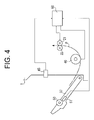
- Fig. 4 is a schematic block diagram illustrating paper feeding control when feeding papers manually.
- Fig. 1 is a schematic sectional view of an overall image forming device according to a preferred embodiment of the present invention.
- An original document scanning unit 2 is arranged on an upper portion of an image forming device 1.
- a paper feeding unit 3 and a recording unit 4 are subsequently arranged from a bottom surface on a lower portion of the image forming device 1.
- an original document placed on an original document tray 11 mounted on an original document cover 10 is transported by an original document transporting device 12 to a position opposite an original document scanning portion, scanned, and discharged onto an original document discharge tray 13.
- the original document cover 10 is opened upward, a portion to be scanned of the book etc. is arranged on a flatbed platen 14, and a scanning operation is carried out at the scanning portion.
- the above-described configuration is similar to a configuration of a conventional original document scanning device including an Auto Document Feeder (an ADF) and a flatbed.
- paper feed cassettes 15 and 16 are vertically arranged and accommodate a plurality of papers of a prescribed size stacked on respective flappers 17 and 18.
- the flappers 17 and 18 are axially supported at a left end portion in Fig. 1 by a hinge.
- Pick up rollers 19 and 20 are arranged on a right side in Fig. 1.
- the flappers 17 and 18 are biased upward so that an upper surface of the stacked papers makes contact with the corresponding pick up rollers 19 or 20. Under such a state, when the pick up rollers 19 or 20 is rotationally driven, the papers are fed to the paper transportation path one sheet at a time by frictional force.
- the recording unit 4 includes a toner container 23, a memory removing brush 24, a charger 25, a photoconductive drum 26, a transfer roller 27, an exposure head 28, and a fuser roller 29.
- a surface of the photoconductive drum 26 is uniformly charged by using the charger 25.
- an electrostatic latent image is formed.
- toner inside the toner container 23 is transferred from a supply roller 30 to the electrostatic latent image formed on the photoconductive drum 26 via a developing roller 31 and visualized.
- a toner image formed on the surface of the photoconductive drum 26 is transferred on the paper by the transfer roller 27. Then, the transferred toner image is fixed to the paper by being heated and pressed by the fuser roller 29 and a pressing roller 32. The fixed paper is nipped between a discharge roller 33 and a pressing roller 34 and discharged onto a paper discharge tray 35.
- a manual paper feed tray 37 is arranged at an accommodating open portion 38.
- the manual paper feed tray 37 is positioned at a closed position by being latched to a device main body by a latching member (not illustrated), however, the manual paper feed tray 37 can turn to an opened position by being axially supported by a turning shaft 39.
- a pick up roller 40 and a pad 41 pressed against the pick up roller 40 are arranged on a lower portion of the accommodating open portion 38 so as to transport a manually fed paper. When the pick up roller 40 is rotated, the manually fed paper is transported along a guide 42 to a portion between the feed roller 21 and the pressing roller 22.
- Fig. 2 is an enlarged partial perspective view illustrating a state in which the manual paper feed tray 37 is positioned at the opened position.
- An upper surface of the manual paper feed tray 37 is a paper placing surface.
- a pair of paper guides 43 are arranged on an upper surface of the manual paper feed tray 37 such that each of the paper guides 34 is arranged on either side of the upper surface.
- the pair of paper guides 43 are attached such that each of the paper guides 43 can move from respective side end portions towards a central portion by fitting to respective linear grooves formed on the upper surface.
- An interlock mechanism (not illustrated) is provided inside the manual paper feed tray 37 such that when one of the guides 43 is moved along the groove, the other guide 43 moves accompanying the former guide 43. Therefore, by placing the paper between the pair of paper guides 43 and moving the paper guides 43 such that the paper guides 43 make contact with respective side ends of the paper, the paper can be placed on a position in accordance with the paper size.
- a pair of protruding portions 44 are provided such that each of the protruding portions 44 is arranged on either side to prevent oblique movement of the paper when feeding the paper.
- a paper setting dial 50 is turnably attached to one of the protruding portions 44.
- An open-close detection sensor 45 for detecting an opening and a closing of the manual paper feed tray 37 is arranged at the accommodating open portion 38 on a device main body side. Accordingly, when the manual paper feed tray 37 is accommodated in the accommodating open portion 38 and closed, an actuating bar (not illustrated) of the open-close detection sensor 45 is pressed by the manual paper feed tray 37, and the open-close detection sensor 45 is turned off. When the manual paper feed tray 37 is turned and opened, the actuating bar of the open-close detection sensor 45 is released from the pressed state and turned on.
- Fig. 3 is an enlarged perspective view of a portion to which the paper setting dial 50 is attached.
- the protruding portion 44 has an arc shape in its sectional view and protrudes in a curved shape. Moreover, a central portion of the protruding portion 44 is cut away for a prescribed width, and the disk-shaped paper setting dial 50 is inserted into the cut-awayportion and axially and turnably supported.
- a mark indicating a size of the paper is displayed around a circumferential surface of the paper setting dial 50. In this example, a mark 50a such as "B5", "A4", "B4", and "A3" is displayed.
- a regulation unit (not illustrated) is provided such that the paper setting dial 50 can be turned by a predetermined angle according to an interval between the marks 50a displayed on the circumferential surface.
- the regulation unit for example, holes may be formed with an interval of a predetermined angle therebetween in a circumferential direction, and an elastic member formed with a protrusion may be arranged to be fitted to the hole.
- a triangular instruction mark 44a is engraved in the vicinity of the paper setting dial 50.
- the paper setting dial 50 is manually turned so that the instruction mark 44a points a mark that indicates the appropriate size.
- the paper setting dial 50 When the paper setting dial 50 is arranged to have a color different from a color of the protruding portion 44, the user can easily view and check the paper setting dial 50. Moreover, it becomes unnecessary to check whether or not the appropriate paper size is set at the operation display panel when the paper is placed on the manual paper feed tray 37. In addition, the setting operation will not be forgotten. For example, when the protruding portion 44 has a light color, it is more preferable to arrange the paper setting dial 50 to have a deep color so that a contrast will be clear.
- a paper size detection sensor 51 for detecting a turned position of the paper setting dial 50 is provided inside the protruding portion 44.
- the paper size detection sensor 51 may optically detect by using a reflection portion or a through hole formed on a side surface of the paper setting dial 50 or electrically detect by attaching a conductive material to the side surface.
- a detection signal corresponding to the paper size mark pointed by the instruction mark 44a is output by the paper size detection sensor 51.
- Fig. 4 is a schematic block diagram illustrating paper feeding control when feeding the paper manually.
- a control unit 60 which controls a manual paper feeding operation, is connected to the open-close detection sensor 45 that detects the opening and the closing of the manual paper feed tray 37 and to the paper size detection sensor 51. The detection signal from each of the detection sensors is input into the control unit 60.
- the control unit 60 does not perform control of manual paper feeding but performs control of paper feeding from the usual paper feed cassette.
- the manual paper feed tray 37 is opened, the open-close detection sensor 45 is turned on, and the control unit 60 checks the detection signal from the paper size detection sensor 51 based on the detection signal from the open-close detection sensor 45.
- the paper setting dial 50 is turned by the user to be set at a prescribed size, the detection signal corresponding to the set paper size is input into the control unit 60, and data about the paper size is registered.
- the control unit 60 When a printing command is input from the operation display panel of the device main body, the control unit 60 starts rotating the pick up roller 40 and performs the manual paper feeding operation.
- the manually fed paper is transported between the feed roller 21 and the pressing roller 22.
- image forming processing is carried out at the recording unit 4 in accordance with the registered paper size.
- the size of the paper that is manually fed by the user can be easily set by the paper setting dial attached to the manual paper feed tray. Further, when placing the paper, the paper setting dial is viewed and checked, and the setting operation of the paper size is reliably carried out.
Landscapes
- Physics & Mathematics (AREA)
- General Physics & Mathematics (AREA)
- Sheets, Magazines, And Separation Thereof (AREA)
- Paper Feeding For Electrophotography (AREA)
- Manual Feeding Of Sheets (AREA)
Abstract
Description
- The present invention relates to an image forming device such as a copier, a facsimile machine, or a printer.
- An image forming device which uses a photoconductive drum, for example, as an image carrier, charges and exposes a surface of the photoconductive drum to form an electrostatic latent image, visualizes the electrostatic latent image by adhering toner to the image, and transfers the adhered toner to a paper, is known as an electrophotographic image forming device. In such an image forming device, image forming processing is performed by transporting papers of various sizes, and the papers of a frequently-used size are placed in a paper feed cassette and fed. However, when using cardboard etc., which cannot be fed easily from the paper feed cassette, the image forming processing is performed by feeding such materials from a manual paper feed tray.
- When using papers of various sizes, it is necessary to perform image processing in accordance with the size of the fed paper. Therefore, the image processing is performed by detecting the size of the paper placed in the paper feed cassette.
- For example, a conventional paper feed cassette includes a configuration in which a switch-and-set dial having a display mark indicating the size of the papers accommodated in an accommodating portion of the paper feed tray is turned and switched, and the paper feed tray is placed in a housing. In the above-described paper feed cassette, when a type and a size indicated by a turned position of the switch-and-set dial are detected by a type-and-size detection sensor, the paper size is determined. In addition, the conventional paper feed cassette includes a configuration in which a paper size setting dial arranged at a front edge of a box of the paper feed tray protrudes upward from the box when the box is drawn out, and makes contact with a front surface of a device main body when the box is inserted.
- In the above-described conventional paper feed cassette, a set dial displaying the size of the papers placed in the paper feed tray is provided to prompt a user to check the paper size. In addition, the set dial is provided to prevent image processing using a paper of a different size. However, the paper size used in the image processing is generally displayed at an operation display panel unit arranged on an upper portion of the device. Therefore, a problem is that it is difficult to check whether or not the paper size displayed at the operation display panel unit matches the paper size displayed on the paper feed cassette that is positioned apart from the operation display panel unit.
- In particular, when feeding the paper from the manual paper feed tray on which various papers are to be placed, it is difficult to check whether or not the size of the placed paper matches the paper size set at the operation display panel unit. In such a case, troubles such as a jam may occur when placing the paper on the manual paper feed tray without checking the paper size set at the operation display panel unit.
- In order to overcome the problems described above, preferred embodiments of the present invention provide an image forming device in which it is easy to check whether or not the size of papers placed on a manual paper feed tray matches a paper size set at an operation display panel unit. Further, it becomes possible to reliably set the paper size without forgetting the setting.
- The image forming device according to a preferred embodiment of the present invention includes a manual paper feed tray, a paper setting dial, a paper size detection unit, and a control unit. The manual paper feed tray is provided in a device main body for feeding the papers manually such that the manual paper feed tray can be opened and closed. The paper setting dial is turnably arranged on a paper placing surface side of the manual paper feed tray and displays the paper size. The paper size detection unit detects a set position of the paper setting dial. The control unit performs paper transportation control based on a detection signal from the paper size detection unit. Moreover, when an open-close detection sensor of the manual paper feed tray detects opened status, the control unit preferably performs the paper transportation control based on the detection signal from the paper size detection unit. Further, the paper setting dial may be arranged to have a color different from a color of the manual paper feed tray. Furthermore, the paper setting dial on the manual paper feed tray may be arranged on a front surface side of the device.
- With the above-described configuration, the size can be set by using the paper setting dial attached to the manual paper feed tray. Moreover, a size setting operation can be easily carried out while checking the placed paper, and the setting is reliably carried out. When the placed paper matches the size set at the paper setting dial, information on the size of the placed paper is reliably output by the paper size detection unit to the device main body, and thus, a paper transporting operation can be stably carried out.
- When the open-close detection sensor of the manual paper feed tray detects the opened status, the paper transportation control is performed based on the detection signal from the paper size detection unit. In the above-described configuration, only under a state in which the manual paper feed tray is under the opened status and the paper can be fed manually, paper transportation can be carried out based on the detection signal from the paper size detection unit. Thus, a manual paper feeding operation can be particularly reliably carried out.
- If the paper setting dial is arranged to have a color different from the color of the manual paper feed tray, a user can easily view and check the paper setting dial, and consequently, the setting operation of the paper size is prompted when the paper is placed on the manual paper feed tray.
- Further, the paper setting dial may be arranged on the front surface side of the device, i.e., on a side on which the user stands when placing the papers on the manual paper feed tray. Accordingly, the paper setting dial can be easily viewed and checked when placing the paper, and the setting will not be forgotten.
- Other features, elements, processes, steps, characteristics and advantages of the present invention will become more apparent from the following detailed description of preferred embodiments of the present invention with reference to the attached drawings.
- Fig. 1 is a schematic sectional view of an overall image forming device according to a preferred embodiment of the present invention.
- Fig. 2 is an enlarged partial perspective view illustrating a state in which a manual paper feed tray is positioned at an open position.
- Fig. 3 is an enlarged perspective view of a portion to which a paper setting dial is attached.
- Fig. 4 is a schematic block diagram illustrating paper feeding control when feeding papers manually.
- A detailed description will be made of a preferred embodiment of the present invention. Since the preferred embodiment described below is a preferable specific example when implementing the present invention, the preferred embodiment has various limitations technically. However, the present invention is not limited to the preferred embodiment as long as it is not particularly specified in the following description that the present invention is limited.
- Fig. 1 is a schematic sectional view of an overall image forming device according to a preferred embodiment of the present invention. An original
document scanning unit 2 is arranged on an upper portion of animage forming device 1. A paper feeding unit 3 and arecording unit 4 are subsequently arranged from a bottom surface on a lower portion of theimage forming device 1. - At the original
document scanning unit 2, an original document placed on anoriginal document tray 11 mounted on anoriginal document cover 10 is transported by an originaldocument transporting device 12 to a position opposite an original document scanning portion, scanned, and discharged onto an originaldocument discharge tray 13. When scanning a book etc., theoriginal document cover 10 is opened upward, a portion to be scanned of the book etc. is arranged on aflatbed platen 14, and a scanning operation is carried out at the scanning portion. The above-described configuration is similar to a configuration of a conventional original document scanning device including an Auto Document Feeder (an ADF) and a flatbed. - In the paper feeding unit 3,
paper feed cassettes respective flappers flappers rollers flappers rollers rollers - The fed paper is transported by a
feed roller 21 and apressing roller 22 to therecording unit 4. In order to record an image on the transported paper, therecording unit 4 includes atoner container 23, amemory removing brush 24, acharger 25, aphotoconductive drum 26, atransfer roller 27, anexposure head 28, and afuser roller 29. First, a surface of thephotoconductive drum 26 is uniformly charged by using thecharger 25. Then, by exposing the chargedphotoconductive drum 26 by theexposure head 28 according to an image recording signal, an electrostatic latent image is formed. Next, toner inside thetoner container 23 is transferred from asupply roller 30 to the electrostatic latent image formed on thephotoconductive drum 26 via a developingroller 31 and visualized. Next, a toner image formed on the surface of thephotoconductive drum 26 is transferred on the paper by thetransfer roller 27. Then, the transferred toner image is fixed to the paper by being heated and pressed by thefuser roller 29 and apressing roller 32. The fixed paper is nipped between adischarge roller 33 and apressing roller 34 and discharged onto apaper discharge tray 35. - On a side surface of the
image forming device 1, a manualpaper feed tray 37 is arranged at an accommodatingopen portion 38. In Fig. 1, the manualpaper feed tray 37 is positioned at a closed position by being latched to a device main body by a latching member (not illustrated), however, the manualpaper feed tray 37 can turn to an opened position by being axially supported by a turningshaft 39. A pick uproller 40 and apad 41 pressed against the pick uproller 40 are arranged on a lower portion of the accommodatingopen portion 38 so as to transport a manually fed paper. When the pick uproller 40 is rotated, the manually fed paper is transported along aguide 42 to a portion between thefeed roller 21 and thepressing roller 22. - Fig. 2 is an enlarged partial perspective view illustrating a state in which the manual
paper feed tray 37 is positioned at the opened position. An upper surface of the manualpaper feed tray 37 is a paper placing surface. A pair of paper guides 43 are arranged on an upper surface of the manualpaper feed tray 37 such that each of the paper guides 34 is arranged on either side of the upper surface. The pair of paper guides 43 are attached such that each of the paper guides 43 can move from respective side end portions towards a central portion by fitting to respective linear grooves formed on the upper surface. An interlock mechanism (not illustrated) is provided inside the manualpaper feed tray 37 such that when one of theguides 43 is moved along the groove, theother guide 43 moves accompanying theformer guide 43. Therefore, by placing the paper between the pair of paper guides 43 and moving the paper guides 43 such that the paper guides 43 make contact with respective side ends of the paper, the paper can be placed on a position in accordance with the paper size. - On an end side farther from the
paper guide 43 on the manualpaper feed tray 37, a pair of protrudingportions 44 are provided such that each of the protrudingportions 44 is arranged on either side to prevent oblique movement of the paper when feeding the paper. Apaper setting dial 50 is turnably attached to one of the protrudingportions 44. By attaching thepaper setting dial 50 on a front surface side of the device, i.e., on a side on which the user stands when placing the paper, the user can easily operate, view, and check thepaper setting dial 50. Therefore, a setting operation will not be forgotten. - An open-
close detection sensor 45 for detecting an opening and a closing of the manualpaper feed tray 37 is arranged at the accommodatingopen portion 38 on a device main body side. Accordingly, when the manualpaper feed tray 37 is accommodated in the accommodatingopen portion 38 and closed, an actuating bar (not illustrated) of the open-close detection sensor 45 is pressed by the manualpaper feed tray 37, and the open-close detection sensor 45 is turned off. When the manualpaper feed tray 37 is turned and opened, the actuating bar of the open-close detection sensor 45 is released from the pressed state and turned on. - Fig. 3 is an enlarged perspective view of a portion to which the
paper setting dial 50 is attached. The protrudingportion 44 has an arc shape in its sectional view and protrudes in a curved shape. Moreover, a central portion of the protrudingportion 44 is cut away for a prescribed width, and the disk-shapedpaper setting dial 50 is inserted into the cut-awayportion and axially and turnably supported. A mark indicating a size of the paper is displayed around a circumferential surface of thepaper setting dial 50. In this example, amark 50a such as "B5", "A4", "B4", and "A3" is displayed. - A regulation unit (not illustrated) is provided such that the
paper setting dial 50 can be turned by a predetermined angle according to an interval between themarks 50a displayed on the circumferential surface. As the regulation unit, for example, holes may be formed with an interval of a predetermined angle therebetween in a circumferential direction, and an elastic member formed with a protrusion may be arranged to be fitted to the hole. Thus, by turning thepaper setting dial 50 manually, thepaper setting dial 50 can be turned by a predetermined angle. - On an outer surface of the protruding
portion 44, atriangular instruction mark 44a is engraved in the vicinity of thepaper setting dial 50. When setting the size of the paper placed on the manualpaper feed tray 37, thepaper setting dial 50 is manually turned so that theinstruction mark 44a points a mark that indicates the appropriate size. - When the
paper setting dial 50 is arranged to have a color different from a color of the protrudingportion 44, the user can easily view and check thepaper setting dial 50. Moreover, it becomes unnecessary to check whether or not the appropriate paper size is set at the operation display panel when the paper is placed on the manualpaper feed tray 37. In addition, the setting operation will not be forgotten. For example, when the protrudingportion 44 has a light color, it is more preferable to arrange thepaper setting dial 50 to have a deep color so that a contrast will be clear. - A paper
size detection sensor 51 for detecting a turned position of thepaper setting dial 50 is provided inside the protrudingportion 44. The papersize detection sensor 51 may optically detect by using a reflection portion or a through hole formed on a side surface of thepaper setting dial 50 or electrically detect by attaching a conductive material to the side surface. Thus, a detection signal corresponding to the paper size mark pointed by theinstruction mark 44a is output by the papersize detection sensor 51. - Fig. 4 is a schematic block diagram illustrating paper feeding control when feeding the paper manually. A
control unit 60, which controls a manual paper feeding operation, is connected to the open-close detection sensor 45 that detects the opening and the closing of the manualpaper feed tray 37 and to the papersize detection sensor 51. The detection signal from each of the detection sensors is input into thecontrol unit 60. - When the manual
paper feed tray 37 is closed and the open-close detection sensor 45 is turned off, thecontrol unit 60 does not perform control of manual paper feeding but performs control of paper feeding from the usual paper feed cassette. When the manualpaper feed tray 37 is opened, the open-close detection sensor 45 is turned on, and thecontrol unit 60 checks the detection signal from the papersize detection sensor 51 based on the detection signal from the open-close detection sensor 45. When thepaper setting dial 50 is turned by the user to be set at a prescribed size, the detection signal corresponding to the set paper size is input into thecontrol unit 60, and data about the paper size is registered. - When a printing command is input from the operation display panel of the device main body, the
control unit 60 starts rotating the pick uproller 40 and performs the manual paper feeding operation. The manually fed paper is transported between thefeed roller 21 and thepressing roller 22. Thus, image forming processing is carried out at therecording unit 4 in accordance with the registered paper size. - As described above, the size of the paper that is manually fed by the user can be easily set by the paper setting dial attached to the manual paper feed tray. Further, when placing the paper, the paper setting dial is viewed and checked, and the setting operation of the paper size is reliably carried out.
- While the present invention has been described with respect to a preferred embodiment thereof, it will be apparent to those skilled in the art that the disclosed invention may be modified in numerous ways and may assume many embodiments other than that specifically set out and described above. Accordingly, the appended claims are intended to cover all modifications of the present invention that fall within the true scope of the present invention.
Claims (5)
- An image forming device (1) that performs image forming processing, comprising:a manual paper feed tray (37) provided for manual paper feeding on a device main body, the manual paper feed tray being arranged to be opened and closed;a paper setting dial (50) turnably attached to a paper placing surface side of the manual paper feed tray, the paper setting dial being arranged to display a paper size;a paper size detection sensor (51) arranged to detect a set position of the paper setting dial; anda control unit (60) arranged to perform paper transportation control based on a detection signal from the paper size detection sensor.
- An image forming device according to claim 1, wherein the control unit performs the paper transportation control based on the detection signal from the paper size detection sensor when an open-close detection sensor (45) of the manual paper feed tray detects opened status.
- An image forming device according to claim 1 or 2, wherein the paper setting dial is arranged to have a color different from a color of the manual paper feed tray.
- An image forming device according to claim 3, wherein the paper setting dial is arranged to have a deep color and the manual paper feed tray 37 has a light color.
- An image forming device according to any preceding claim, wherein the paper setting dial is arranged on a device front surface side of the manual paper feed tray.
Applications Claiming Priority (1)
| Application Number | Priority Date | Filing Date | Title |
|---|---|---|---|
| JP2006224680A JP4179362B2 (en) | 2006-08-21 | 2006-08-21 | Image forming apparatus |
Publications (2)
| Publication Number | Publication Date |
|---|---|
| EP1892580A2 true EP1892580A2 (en) | 2008-02-27 |
| EP1892580A3 EP1892580A3 (en) | 2013-10-16 |
Family
ID=38796073
Family Applications (1)
| Application Number | Title | Priority Date | Filing Date |
|---|---|---|---|
| EP07112785.6A Withdrawn EP1892580A3 (en) | 2006-08-21 | 2007-07-19 | Image forming device having a manual paper feed tray |
Country Status (4)
| Country | Link |
|---|---|
| US (1) | US20080044208A1 (en) |
| EP (1) | EP1892580A3 (en) |
| JP (1) | JP4179362B2 (en) |
| CN (1) | CN101131552A (en) |
Families Citing this family (3)
| Publication number | Priority date | Publication date | Assignee | Title |
|---|---|---|---|---|
| JP6155748B2 (en) * | 2013-03-27 | 2017-07-05 | セイコーエプソン株式会社 | Printer and printer control method |
| US10498913B2 (en) * | 2016-07-29 | 2019-12-03 | Canon Kabushiki Kaisha | Image forming apparatus |
| JP7322486B2 (en) * | 2019-04-17 | 2023-08-08 | 京セラドキュメントソリューションズ株式会社 | image forming system |
Family Cites Families (6)
| Publication number | Priority date | Publication date | Assignee | Title |
|---|---|---|---|---|
| GB1552923A (en) * | 1975-11-14 | 1979-09-19 | Iwatsu Electric Co Ltd | Apparatus for making plates for printing |
| JPS5511268A (en) * | 1978-07-12 | 1980-01-26 | Minolta Camera Co Ltd | Copying machine |
| US5125636A (en) * | 1989-01-30 | 1992-06-30 | Minolta Camera Kabushiki Kaisha | Copying machine capable of copying two originals on one sheet of paper |
| US5923942A (en) * | 1997-11-14 | 1999-07-13 | Ricoh Company, Ltd. | Printer and paper tray having a user programmable paper size |
| JP3797307B2 (en) * | 2002-09-30 | 2006-07-19 | ブラザー工業株式会社 | Paper feeding device, image forming apparatus having the same, and apparatus control program |
| JP2006201507A (en) * | 2005-01-20 | 2006-08-03 | Kyocera Mita Corp | Image forming apparatus |
-
2006
- 2006-08-21 JP JP2006224680A patent/JP4179362B2/en not_active Expired - Fee Related
-
2007
- 2007-07-19 EP EP07112785.6A patent/EP1892580A3/en not_active Withdrawn
- 2007-08-08 US US11/835,479 patent/US20080044208A1/en not_active Abandoned
- 2007-08-21 CN CNA2007101417178A patent/CN101131552A/en active Pending
Also Published As
| Publication number | Publication date |
|---|---|
| US20080044208A1 (en) | 2008-02-21 |
| EP1892580A3 (en) | 2013-10-16 |
| JP2008044781A (en) | 2008-02-28 |
| CN101131552A (en) | 2008-02-27 |
| JP4179362B2 (en) | 2008-11-12 |
Similar Documents
| Publication | Publication Date | Title |
|---|---|---|
| JP2012158422A (en) | Sheet feeder and image forming apparatus | |
| US20200198909A1 (en) | Sheet feed device for restricting noise generation, image forming apparatus | |
| US10108128B2 (en) | Automatic document feeder, image reading device incorporating the automatic document feeder, and image forming apparatus incorporating the image reading device with the automatic document feeder | |
| US7894097B2 (en) | Image forming apparatus with controller to control operation based on open or closed state of upper portion of apparatus | |
| US8757616B2 (en) | Sheet feeding mechanism and image forming apparatus provided with the same | |
| CN104345601B (en) | Paper feed and image processing system | |
| US20080044208A1 (en) | Image forming device | |
| JP4135103B2 (en) | Image forming apparatus | |
| JP4613538B2 (en) | Image forming apparatus | |
| JP2019040127A (en) | Lock mechanism for movable unit and sheet conveying device including the same, and image forming apparatus | |
| JP2004307107A (en) | Paper tray, and automatic paper feeder and image forming apparatus including the same | |
| JP7638670B2 (en) | Image forming device | |
| JP6051314B2 (en) | Sheet feeding device and image forming apparatus provided with the same | |
| US10564585B2 (en) | Sheet feeding device and image forming apparatus including the same | |
| JP4143551B2 (en) | Image forming apparatus | |
| JP7709903B2 (en) | Image forming device | |
| JP5156558B2 (en) | Sheet conveying device, sheet feeding device and image forming apparatus including the same | |
| JP7508273B2 (en) | Image forming device | |
| JP2024154322A (en) | Image forming apparatus and replacement method | |
| JP3338166B2 (en) | Image forming device | |
| JP2008120502A (en) | Image forming device | |
| JP3604671B2 (en) | Image forming device | |
| JPH10153939A (en) | Image forming device | |
| JP2004106970A (en) | Image forming device | |
| HK1112647A (en) | Image forming device |
Legal Events
| Date | Code | Title | Description |
|---|---|---|---|
| PUAI | Public reference made under article 153(3) epc to a published international application that has entered the european phase |
Free format text: ORIGINAL CODE: 0009012 |
|
| AK | Designated contracting states |
Kind code of ref document: A2 Designated state(s): AT BE BG CH CY CZ DE DK EE ES FI FR GB GR HU IE IS IT LI LT LU LV MC MT NL PL PT RO SE SI SK TR |
|
| AX | Request for extension of the european patent |
Extension state: AL BA HR MK YU |
|
| PUAL | Search report despatched |
Free format text: ORIGINAL CODE: 0009013 |
|
| AK | Designated contracting states |
Kind code of ref document: A3 Designated state(s): AT BE BG CH CY CZ DE DK EE ES FI FR GB GR HU IE IS IT LI LT LU LV MC MT NL PL PT RO SE SI SK TR |
|
| AX | Request for extension of the european patent |
Extension state: AL BA HR MK RS |
|
| RIC1 | Information provided on ipc code assigned before grant |
Ipc: G03G 15/00 20060101AFI20130909BHEP |
|
| AKY | No designation fees paid | ||
| REG | Reference to a national code |
Ref country code: DE Ref legal event code: R108 |
|
| STAA | Information on the status of an ep patent application or granted ep patent |
Free format text: STATUS: THE APPLICATION IS DEEMED TO BE WITHDRAWN |
|
| REG | Reference to a national code |
Ref country code: DE Ref legal event code: R108 Effective date: 20140625 |
|
| 18D | Application deemed to be withdrawn |
Effective date: 20140201 |