EP1892579A1 - Image forming apparatus with display unit removable from apparatus main body - Google Patents
Image forming apparatus with display unit removable from apparatus main body Download PDFInfo
- Publication number
- EP1892579A1 EP1892579A1 EP06025026A EP06025026A EP1892579A1 EP 1892579 A1 EP1892579 A1 EP 1892579A1 EP 06025026 A EP06025026 A EP 06025026A EP 06025026 A EP06025026 A EP 06025026A EP 1892579 A1 EP1892579 A1 EP 1892579A1
- Authority
- EP
- European Patent Office
- Prior art keywords
- image forming
- display unit
- forming apparatus
- display
- main body
- Prior art date
- Legal status (The legal status is an assumption and is not a legal conclusion. Google has not performed a legal analysis and makes no representation as to the accuracy of the status listed.)
- Granted
Links
Images







Classifications
-
- H—ELECTRICITY
- H04—ELECTRIC COMMUNICATION TECHNIQUE
- H04N—PICTORIAL COMMUNICATION, e.g. TELEVISION
- H04N1/00—Scanning, transmission or reproduction of documents or the like, e.g. facsimile transmission; Details thereof
- H04N1/0035—User-machine interface; Control console
- H04N1/00496—Constructional details of the interface or console not otherwise provided for, e.g. rotating or tilting means
-
- G—PHYSICS
- G03—PHOTOGRAPHY; CINEMATOGRAPHY; ANALOGOUS TECHNIQUES USING WAVES OTHER THAN OPTICAL WAVES; ELECTROGRAPHY; HOLOGRAPHY
- G03G—ELECTROGRAPHY; ELECTROPHOTOGRAPHY; MAGNETOGRAPHY
- G03G15/00—Apparatus for electrographic processes using a charge pattern
- G03G15/50—Machine control of apparatus for electrographic processes using a charge pattern, e.g. regulating differents parts of the machine, multimode copiers, microprocessor control
- G03G15/5016—User-machine interface; Display panels; Control console
-
- G—PHYSICS
- G03—PHOTOGRAPHY; CINEMATOGRAPHY; ANALOGOUS TECHNIQUES USING WAVES OTHER THAN OPTICAL WAVES; ELECTROGRAPHY; HOLOGRAPHY
- G03G—ELECTROGRAPHY; ELECTROPHOTOGRAPHY; MAGNETOGRAPHY
- G03G15/00—Apparatus for electrographic processes using a charge pattern
- G03G15/70—Detecting malfunctions relating to paper handling, e.g. jams
-
- H—ELECTRICITY
- H04—ELECTRIC COMMUNICATION TECHNIQUE
- H04N—PICTORIAL COMMUNICATION, e.g. TELEVISION
- H04N1/00—Scanning, transmission or reproduction of documents or the like, e.g. facsimile transmission; Details thereof
- H04N1/0035—User-machine interface; Control console
- H04N1/00405—Output means
- H04N1/00408—Display of information to the user, e.g. menus
-
- H—ELECTRICITY
- H04—ELECTRIC COMMUNICATION TECHNIQUE
- H04N—PICTORIAL COMMUNICATION, e.g. TELEVISION
- H04N1/00—Scanning, transmission or reproduction of documents or the like, e.g. facsimile transmission; Details thereof
- H04N1/0083—Arrangements for transferring signals between different components of the apparatus, e.g. arrangements of signal lines or cables
-
- H—ELECTRICITY
- H04—ELECTRIC COMMUNICATION TECHNIQUE
- H04N—PICTORIAL COMMUNICATION, e.g. TELEVISION
- H04N2201/00—Indexing scheme relating to scanning, transmission or reproduction of documents or the like, and to details thereof
- H04N2201/0077—Types of the still picture apparatus
- H04N2201/0094—Multifunctional device, i.e. a device capable of all of reading, reproducing, copying, facsimile transception, file transception
Definitions
- the present invention relates to an image forming apparatus and a method of controlling the image forming apparatus, and more particularly to an image forming apparatus for displaying information on a display unit that is removable from an apparatus main body and a method of controlling the image forming apparatus.
- Patent Document 1 discloses an image forming apparatus that allows a display unit to be removed therefrom or allows the angle of a display screen to be changed so that, upon handling a jam or the like, action can be easily taken while viewing the display unit, which in turn does not require cumbersome actions such as standing up and crouching down.
- Patent Document 2 discloses an image forming apparatus in which, when a detachable panel is placed at the rear of an MFP, a panel for a service person is depicted.
- Patent Document 3 discloses an image forming apparatus including an operating unit whose placement location can be changed.
- Patent Document 4 discloses a technique for providing a jam location display apparatus inside an apparatus in order to display a jam location in a paper transporting portion of a copier or the like. First display in a rough display manner and second display in a detailed display manner are provided.
- Patent Document 5 discloses that in addition to an LCD display apparatus provided at the top of a main body, a second LCD display apparatus is installed inside the apparatus main body so that, upon performing maintenance, work can be performed referring to the second LCD display apparatus.
- a displaying portion can be moved to some locations in an apparatus main body, and in the technique of Patent Document 2 the mounting location of a displaying portion is moved and thereby displayed content can be changed. This improves visibility.
- a display apparatus needs to be viewed in a state in which the display apparatus is mounted on an apparatus main body, upon performing maintenance, jam handling, or the like, in the vicinity of the apparatus, display cannot be checked at any free location and thus it cannot be said that operability is satisfactory.
- a plurality of displaying portions are provided and allowed to display independently, whereby visibility can be enhanced.
- the displaying portions are fixed to an apparatus main body, upon performing maintenance, jam handling, or the like, in the vicinity of the apparatus, display cannot be checked at any free location and thus it cannot be said that operability is satisfactory.
- An object of the present invention is therefore to provide an image forming apparatus capable of improving user operability and a method of controlling the image forming apparatus.
- an image forming apparatus includes: a transmitting portion that transmits information from an apparatus main body to a removable display unit; a detecting portion that detects a positional relationship between the display unit being removed and the apparatus main body; and a controlling portion that determines a content to be displayed on the display unit, based on a detection result obtained by the detecting portion and controls the content to be displayed on the display unit using the transmitting portion.
- a method of controlling an image forming apparatus including a transmitting portion that transmits information from an apparatus main body to a removable display unit, the method including the steps of: detecting a positional relationship between the display unit being removed from the apparatus main body and the apparatus main body; and determining content to be displayed on the display unit, based on a detection result obtained in the detecting step and controlling the content to be displayed on the display unit using the transmitting portion.
- Fig. 1 is a block diagram showing an overall configuration of an image forming apparatus according to one embodiment of the present invention.
- Fig. 2 is a diagram showing an external appearance of a detachable display 200.
- Fig. 3 is a diagram showing an internal structure of an image forming apparatus 100.
- Fig. 4 is a flowchart showing a process performed by the image forming apparatus.
- Figs. 5 and 6 are diagrams showing exemplary detection of a location of detachable display 200.
- Fig. 7 is a diagram showing a state in which a user holds detachable display 200 in his/her hand over image forming apparatus main body 100.
- Figs. 8 to 14 are diagrams showing exemplary display on detachable display 200.
- Figs. 15 to 18 are diagrams showing exemplary control tables.
- Fig. 19 is a diagram showing a table for determining a picture of the image forming apparatus to be displayed based on the location and direction of the detachable display.
- Fig. 20 is a flowchart showing an internal process of detachable display 200.
- Fig. 21 is a flowchart showing an internal process of image forming apparatus main body 100.
- Fig. 22 is a diagram for describing a first mechanism for detecting a location of the detachable display.
- Fig. 23 is a diagram for describing a second mechanism for detecting a location of the detachable display.
- Fig. 24 is a diagram for describing a mechanism for detecting a direction of the detachable display.
- a display unit of an operating portion is configured to be detachable from an apparatus main body.
- an image forming apparatus main body 100 has a location information receiving portion 113 serving as a communication apparatus that performs communication with a detachable display 200, a direction information receiving portion 115, a display mode receiving portion 117, and a display information transmitting portion 119.
- the display information transmitting portion 119 transmits optimal displayed content to detachable display 200.
- image forming apparatus main body 100 includes a machine condition detecting portion 103 that detects machine conditions; a user identifying portion 105 that identifies a user by a display mode or the like received from detachable display 200; a controlling portion 101 that controls displayed content based on data received from detachable display 200, machine conditions detected by image forming apparatus main body 100, user type data, and the like; and a data storing portion 107 that stores received data and controlled data.
- Image forming apparatus main body 100 includes an operating portion 111 that accepts an operation from a user; and a displaying portion 109 that provides display of information to a user. Furthermore, image forming apparatus main body 100 includes mounting portions 151a, 151b ... for mounting detachable display 200.
- Image forming apparatus main body 100 further includes members relating to image formation and image reading/storage, such as a scanner 121, a print engine 123, a communicating portion 125, and a storing portion 127.
- members relating to image formation and image reading/storage such as a scanner 121, a print engine 123, a communicating portion 125, and a storing portion 127.
- Detachable display 200 includes a location information detecting portion 209 that detects a location of the display; a direction information detecting portion 211 that detects a tilt and an orientation; an operating portion 213 to be operated when a service engineer or the like performs a specific operation; a displaying portion 215; a location information transmitting portion 201 that transmits detected location information, tilt information, display mode to image forming apparatus main body 100; a direction information transmitting portion 203; a display mode transmitting portion 205; and a display information receiving portion 207 that receives display information to be transmitted from image forming apparatus main body 100.
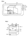
- Fig. 2 is a diagram showing an external appearance of detachable display 200.
- detachable display 200 has location information detecting portion 209 for detecting a positional relationship between image forming apparatus main body 100 and detachable display 200, and a tilt ,sensor 211a that detects a direction (orientation and tilt) of detachable display 200. Furthermore, detachable display 200 includes location/direction (tilt) information transmitting portions 201 and 203 that transmit tilt information detected by tilt sensor 211 a and location information detected by location information detecting portion 209, to image forming apparatus main body 100.
- detachable display 200 includes a key 213a used to perform a specific operation (mode display) by a service engineer for maintenance or the like; display mode transmitting portion 205 (Fig. 1) that transmits a mode currently being displayed; display information receiving portion 207 that receives display information to be transmitted from image forming apparatus main body 100; and displaying portion 215 that displays the information received by display information receiving portion 207.
- mode display a specific operation
- display mode transmitting portion 205 Fig. 1
- display information receiving portion 207 that receives display information to be transmitted from image forming apparatus main body 100
- displaying portion 215 that displays the information received by display information receiving portion 207.
- Fig. 3 is a diagram showing an internal structure (a portion for communicating with the detachable display) of image forming apparatus 100.
- Image forming apparatus 100 includes location information receiving portion 113 that receives location information to be transmitted from detachable display 200; and a display information controlling portion 101 a that controls content to be displayed on detachable display 200, taking into consideration a location/direction between image forming apparatus main body 100 and detachable display 200 and conditions of image forming apparatus main body 100. Furthermore, image forming apparatus 100 includes display information transmitting portion 119 that transmits display information determined by display information controlling portion 101 a, to detachable display 200. Image forming apparatus main body 100 also includes an operating panel (composed of displaying portion 109 and operating portion 111).
- image forming apparatus main body 100 includes mounting portions 151a, 151b ... for mounting detachable display 200.
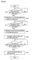
- Fig. 4 is a flowchart showing a process performed by the image forming apparatus.
- step S101 conditions (occurrence of error or trouble, operating conditions, etc.) of the image forming apparatus are detected.
- step S 103 the location and direction (tilt) of detachable display 200 are detected.
- step S105 a display mode, whether it is in a normal mode or maintenance mode for example, is detected.
- step S 107 based on detection results obtained in steps S101 to S 105, content to be displayed on detachable display 200 is determined. Thereafter, in step S109, display information is transmitted to detachable display 200, whereby detachable display 200 provides display.
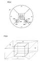
- Figs. 5 and 6 are diagrams showing exemplary detection of the location and direction of detachable display 200.
- Fig. 5 is a diagram of the image forming apparatus main body and its periphery as viewed from above
- Fig. 6 is a diagram of an upper half of the image forming apparatus main body as viewed from an angle.
- Each boundary is a line extending in a direction of 45 degrees from a corner of the machine.
- the aforementioned predetermined distance is one meter from a circumference of the image forming apparatus. If exceeding this, it is recognized that detachable display 200 is at a location far from the main body and thus the detachable display 200 is determined to be in the area (5).
- a periphery of the upper half of the image forming apparatus main body is divided into the areas (1) to (4).
- a periphery of a lower half of the image forming apparatus main body is similarly divided into the areas (1) to (4).
- an area at the top of the main body may also be considered. That is, when the display is mounted on or held over the area at the top of the main body, the display may display for the top, or only when the display is mounted on or held over space immediately above the main body, display for the top may be provided.
- a direction (orientation and tilt) of the display is detected. For example, the cases of a to c and d to f are detected.
- a surface denoted by DSP is a display surface.
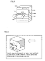
- Fig. 7 is a diagram showing a state in which the user holds detachable display 200 in his/her hand over image forming apparatus main body 100.
- reference numeral 161 denotes a side door and reference numeral 163 denotes a paper feed cassette.
- a jam When a jam has occurred, display informing of the occurrence of a jam is provided on the display of displaying portion 109 (Fig. 1) of image forming apparatus main body 100.
- displaying portion 109 FIG. 1
- the user sees the display opens the front door, and holds detachable display 200 in his/her hand over the location a in Fig. 5 (the upper half of the main body), for example, an orientation and a tilt are detected by direction sensor 211a in Fig. 2.
- a location of detachable display 200 is detected by location information detecting portion 209.
- location information/tilt information transmitting portions 201 and 203 information is transmitted to image forming apparatus main body 100.
- location information/direction information receiving portions 113 and 115 receive the location information and the direction information and then transmit the information to display information controlling portion 101a.
- Display information controlling portion 101a determines optimal information, taking into consideration the received direction information and location information and conditions (here, a jam is being occurred) of the image forming apparatus, and then display information is transmitted by display information transmitting portion 119 to detachable display 200.
- the "optimal information” includes a diagram of the main body as viewed from the location of detachable display 200 and information for instructing the user to clear the jam.
- the optimal information is received by display information receiving portion 207 and then displayed on displaying portion 215.
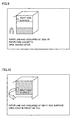
- Fig. 8 is a diagram showing exemplary display on detachable display 200.
- exemplary display in a state in which a general user uses the display, a fusing/paper feed jam has occurred, the detachable display is held over the image forming apparatus main body from the top of the front door diagonally forward right, and the front door of the image forming apparatus is open.
- Displayed content here includes a picture of the front door viewed from diagonally forward right, with the upper half of image forming apparatus main body 100 being centered (close-up). By seeing the displayed content, the user can know the location where the jam has occurred and a handling method therefor (method of opening and closing doors).
- the image forming apparatus main body 100 detects by a side door open/close detecting apparatus 103a (Fig. 7) that the side door has been opened, displays, taking into consideration a jam state, an image showing a state in which the side door is open, on the displaying portion of detachable display 200, and instructs, for example, to open a cover of the fusing portion. By repeating this, the user can smoothly handle the jam.
- exemplary display in a state in which the general user uses the display, a fusing/paper feed jam has occurred, the detachable display is held over the image forming apparatus at a forward lower side of the right side door, and the doors of the image forming apparatus are closed.
- a service engineer opens the front door and holds the detachable display over a forward side of the front door, displayed content such as that shown in Fig. 12 is provided.
- the service engineer sees the jam occurrence rate and trouble occurrence rate of each portion and a counter value, for reference to malfunctions of components and uses them as guidelines for suggestions for replacing the components, or the like.
- jam frequency a representative counter value
- Content (categories) to be displayed may be changeable by a specific operation by the service engineer.
- the jam frequency in Fig. 12 is expressed as a fraction; counting starts at the time when the machine is installed (or when the counter value is cleared) and the number of operations performed is set as the denominator (e.g., the number of times paper has been fed from a paper feed cassette 1 is 120) and the number of times, among the operations, paper fails to be fed through is set as the numerator (the number of paper feed jams in the paper feed cassette 1 is 2).
- the detachable display When a jam and machine trouble have occurred at the same time and the detachable display is mounted on the rear side of the main body (or when the detachable display is held over the rear side), if the user who uses the detachable display is a general user, displayed content shown in Fig. 13 is provided and if the user who uses the detachable display is a service engineer, displayed content such as that shown in Fig. 14 is provided. In a jam and machine trouble, the machine trouble is more serious in terms of the conditions of the main body and thus jam information is not displayed. As such, depending on the degree of seriousness of the conditions, displayed content is determined.
- detachable display 200 has different displayed content with different machine conditions, different types of user who uses the detachable display, and different locations and directions of the detachable display.
- Image forming apparatus main body 100 controls displayed content based on location information, direction information, and display mode information from detachable display 200 and machine condition information detected by the main body, which is performed according to tables shown in Figs. 15 to 18.
- Figs. 15 to 18 are diagrams showing exemplary control tables.
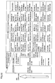
- Fig. 15 is a diagram showing displayed content provided when a general user operates detachable display 200 in a state in which a door (and/or a cassette) is/are closed
- Displayed content is described according to the location of detachable display 200, for each case of normal time, occurrence of attention, occurrence of a jam (in each of a paper feed slot, a fusing portion, and a paper ejecting portion), and occurrence of trouble.
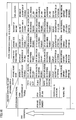
- Fig. 16 is a diagram showing displayed content provided when a service engineer operates detachable display 200 in a state in which a door (and/or a cassette) is/are closed.
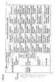
- Fig. 17 is a diagram showing displayed content provided when the general user operates detachable display 200 in a state in which a door (and/or a cassette) is/are open.
- Fig. 18 is a diagram showing displayed content provided when the service engineer operates detachable display 200 in a state in which a door (and/or a cassette) is/are open.
- an event that is serious (event of bad conditions) in terms of machine conditions is displayed on a higher priority basis.
- the higher the event listed the higher the degree of seriousness.
- the upper event is displayed.
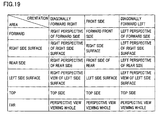
- Fig. 19 is a diagram showing a table for determining a picture of the image forming apparatus to be displayed based on the location (area) and direction of the detachable display.
- a picture of the image forming apparatus to be displayed is determined based on the area and direction.
- a distinction is made between forward, right side surface, rear side, left side surface, top, and far (the areas (1), (2), (3), (4), and (5) in Fig. 5, respectively)
- the orientation of the detachable display a distinction is made between three items, diagonally forward right, front side, and diagonally forward left.
- the tilt a distinction is made between upward and downward directions, and based on that, different display may be provided.
- Fig. 20 is a flowchart showing an internal process of detachable display 200.
- step S201 a determination is made as to whether location information has been changed by movement of the detachable display. If YES, then, in step S203 the location information is transmitted to the image forming apparatus main body.
- step S205 a determination is made as to whether direction information has been changed by change in the tilt of the detachable display. If YES, then, in step S207 the direction information is transmitted to the image forming apparatus main body.
- step S209 a display mode (whether the detachable display is used by a general user or a service engineer, for example) is transmitted to the image forming apparatus main body.
- step S211 a determination is made as to whether display information has been received from the image forming apparatus main body. If YES, then, in step S213, the received information is displayed on displaying portion 215.
- the location information/tilt information are changed by detachable display 200 being held in user's hand, for example, the location information/tilt information are transmitted to the main body.
- a display mode is detected and information is transmitted to the main body.
- Fig. 21 is a flowchart showing an internal process of image forming apparatus main body 100.
- step S301 and S303 when location information and tilt information are transmitted from detachable display 200, the image forming apparatus main body side receives the information.
- step S305 machine conditions (and a display mode) are detected, and in step S307 optimal information that takes into consideration the information from the detachable display is obtained from data storing portion 107.
- step S309 display information is transmitted to the detachable display.
- detachable display 200 receives the display information from image forming apparatus main body 100, detachable display 200 displays content thereof on the displaying portion.
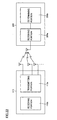
- Fig. 22 is a diagram for describing a first mechanism for detecting a location of the detachable display.
- a transmitting portion 113a having a plurality of antennas and a receiving portion 113b are provided to location information receiving portion 113 of the image forming apparatus main body.
- the plurality of antennas are installed with a predetermined interval provided therebetween.
- the antennas are installed on the front side, plurality of side surfaces, and top side of the image forming apparatus main body.
- Location information detecting portion 209 of the detachable display includes a receiving portion 209a and a determining portion 209b.
- Receiving portion 209a receives radio waves from the plurality of antennas of the image forming apparatus main body.
- Determining portion 209b determines a location of the detachable display by the strengths of the received radio waves.
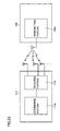
- Fig. 23 is a diagram for describing a second mechanism for detecting a location of the detachable display.
- a receiving portion 113c having a plurality of antennas and a determining portion 113d are provided to location information receiving portion 113 of the image forming apparatus main body.
- the plurality of antennas are installed with a predetermined interval provided therebetween.
- the antennas are installed on the front side, plurality of side surfaces, and top side of the image forming apparatus main body.
- Location information detecting portion 209 of the detachable display includes a transmitting portion 209c.
- Receiving portion 113c receives radio waves from the plurality of antennas of the image forming apparatus main body.
- Determining portion 113d detects phase shifts of signals (or strengths of the radio waves) received by the plurality of antennas and thereby determines a location of the detachable display.
- Fig. 24 is a diagram for describing a mechanism for detecting a direction (orientation and tilt) of the detachable display.
- a receiving portion 211 a having a plurality of antennas and a determining portion 21 1b are provided to direction information receiving portion 211 of the detachable display.
- the plurality of antennas are installed with a predetermined interval provided therebetween.
- Direction information receiving portion 115 of image forming apparatus main body 100 includes a transmitting portion 115a and a receiving portion 115b.
- Direction information detecting portion 211 of the detachable display receives a radio wave from an antenna of the image forming apparatus main body.
- Determining portion 211b detects phase shifts of signals received by the plurality of antennas and thereby determines a direction of the detachable display.
- a sensor such as an acceleration sensor may be provided to the detachable display and the direction may be detected based on an output from the sensor.
- a plurality of location detection transmitters may be provided to the detachable display, radio waves may be outputted from the transmitters, and the image forming apparatus main body that includes a radio wave receiver may receive the radio waves.
- the image forming apparatus detects the location and direction of the detachable display by the strengths of the received radio waves.
- the detachable display when the detachable display is mounted on the image forming apparatus main body, only a mounting location may be detected and a tilt (direction) may not be detected.
- the location may be detected.
- a location at which a person holding the detachable display stands may be detected by an infrared sensor or the like, and thereby a location of the detachable display may be detected.
- the image forming apparatus main body includes two displays, a permanent operating panel (display) and a detachable display
- a permanent operating panel display
- a detachable display it is also possible to provide an image forming apparatus that includes only a detachable display without including an operating panel in a main body.
- User identifying portion 105 may be included in the image forming apparatus main body or user identification may be performed by detachable display 200.
- a system may be used in which the image forming apparatus is connected to a server and the server performs user identification.
- detachable display 200 when the backside of detachable display 200 is not orientated toward a direction of the image forming apparatus main body, nothing may be displayed or the same display as that for the area (5) in Fig. 5 may be provided.
- a boundary between areas is a straight line having a tilt of 45 degrees from a straight line composing a perimeter of the machine and an area range covers a distance of one meter from the image forming apparatus main body, other specifications may be employed.
- a user does not need to perform cumbersome actions and only by carrying a detachable display and moving, the user can obtain accurate information according to a place where work is performed and thus can smoothly perform work.
- the user can obtain accurate information according to a place where work is performed and thus can smoothly perform work.
- optimal information that is determined based on that location/direction and machine conditions can be obtained.
- a positional relationship between the display unit and the apparatus main body is detected and based on a detection result, content to be displayed on the display unit is determined, making it possible to provide an image forming apparatus capable of improving user operability and a method of controlling the image forming apparatus.
- the present invention can be implemented in image forming apparatuses such as MFPs, facsimile apparatuses, copiers, and PCs.
- the processes in the aforementioned embodiment may be performed by software or may be performed using a hardware circuit.
- a program that performs the processes in the aforementioned embodiment can also be provided and the program may be stored in a storage medium, such as a CD-ROM, a flexible disk, a hard disk, a ROM, a RAM, or a memory card, and then provided to a user.
- the program may be downloaded to an apparatus via a communication line such as the Internet.
Landscapes
- Engineering & Computer Science (AREA)
- Multimedia (AREA)
- Signal Processing (AREA)
- Physics & Mathematics (AREA)
- General Physics & Mathematics (AREA)
- Microelectronics & Electronic Packaging (AREA)
- Human Computer Interaction (AREA)
- Facsimiles In General (AREA)
- Control Or Security For Electrophotography (AREA)
- Accessory Devices And Overall Control Thereof (AREA)
- Electrophotography Configuration And Component (AREA)
Abstract
Description
- This application is based on
Japanese Patent Application No. 2006-225449 - The present invention relates to an image forming apparatus and a method of controlling the image forming apparatus, and more particularly to an image forming apparatus for displaying information on a display unit that is removable from an apparatus main body and a method of controlling the image forming apparatus.
- Conventionally, image forming apparatuses such as MFPs (Multi Function Peripherals), copiers, and printers have been known.
-
Japanese Laid-Open Patent Publication No. 08-039894 -
Japanese Laid-Open Patent Publication No. 2004-302307 -
Japanese Laid-Open Patent Publication No. 08-146688 -
Japanese Laid-Open Patent Publication No. 02-147545 -
Japanese Laid-Open Patent Publication No. 09-134049 - In the techniques of
Patent Documents 1 and 3 a displaying portion can be moved to some locations in an apparatus main body, and in the technique ofPatent Document 2 the mounting location of a displaying portion is moved and thereby displayed content can be changed. This improves visibility. However, since in any of the techniques a display apparatus needs to be viewed in a state in which the display apparatus is mounted on an apparatus main body, upon performing maintenance, jam handling, or the like, in the vicinity of the apparatus, display cannot be checked at any free location and thus it cannot be said that operability is satisfactory. - According to the
Patent Documents - An object of the present invention is therefore to provide an image forming apparatus capable of improving user operability and a method of controlling the image forming apparatus.
- To attain the above-described object, according to one aspect of the present invention, an image forming apparatus includes: a transmitting portion that transmits information from an apparatus main body to a removable display unit; a detecting portion that detects a positional relationship between the display unit being removed and the apparatus main body; and a controlling portion that determines a content to be displayed on the display unit, based on a detection result obtained by the detecting portion and controls the content to be displayed on the display unit using the transmitting portion.
- According to another aspect of the present invention, a method of controlling an image forming apparatus including a transmitting portion that transmits information from an apparatus main body to a removable display unit, the method including the steps of: detecting a positional relationship between the display unit being removed from the apparatus main body and the apparatus main body; and determining content to be displayed on the display unit, based on a detection result obtained in the detecting step and controlling the content to be displayed on the display unit using the transmitting portion.
- The foregoing and other objects, features, aspects and advantages of the present invention will become more apparent from the following detailed description of the present invention when taken in conjunction with the accompanying drawings.
- Fig. 1 is a block diagram showing an overall configuration of an image forming apparatus according to one embodiment of the present invention.
- Fig. 2 is a diagram showing an external appearance of a
detachable display 200. - Fig. 3 is a diagram showing an internal structure of an
image forming apparatus 100. - Fig. 4 is a flowchart showing a process performed by the image forming apparatus.
- Figs. 5 and 6 are diagrams showing exemplary detection of a location of
detachable display 200. - Fig. 7 is a diagram showing a state in which a user holds
detachable display 200 in his/her hand over image forming apparatusmain body 100. - Figs. 8 to 14 are diagrams showing exemplary display on
detachable display 200. - Figs. 15 to 18 are diagrams showing exemplary control tables.
- Fig. 19 is a diagram showing a table for determining a picture of the image forming apparatus to be displayed based on the location and direction of the detachable display.
- Fig. 20 is a flowchart showing an internal process of
detachable display 200. - Fig. 21 is a flowchart showing an internal process of image forming apparatus
main body 100. - Fig. 22 is a diagram for describing a first mechanism for detecting a location of the detachable display.
- Fig. 23 is a diagram for describing a second mechanism for detecting a location of the detachable display.
- Fig. 24 is a diagram for describing a mechanism for detecting a direction of the detachable display.
- Referring to the drawings, an image forming apparatus according to one embodiment of the present invention will be described below. In the image forming apparatus which is a copier or the like, a display unit of an operating portion is configured to be detachable from an apparatus main body.
- As shown in Fig. 1, an image forming apparatus
main body 100 has a locationinformation receiving portion 113 serving as a communication apparatus that performs communication with adetachable display 200, a directioninformation receiving portion 115, a displaymode receiving portion 117, and a displayinformation transmitting portion 119. The displayinformation transmitting portion 119 transmits optimal displayed content todetachable display 200. - In addition, image forming apparatus
main body 100 includes a machinecondition detecting portion 103 that detects machine conditions; auser identifying portion 105 that identifies a user by a display mode or the like received fromdetachable display 200; a controllingportion 101 that controls displayed content based on data received fromdetachable display 200, machine conditions detected by image forming apparatusmain body 100, user type data, and the like; and adata storing portion 107 that stores received data and controlled data. - Image forming apparatus
main body 100 includes anoperating portion 111 that accepts an operation from a user; and a displayingportion 109 that provides display of information to a user. Furthermore, image forming apparatusmain body 100 includes mountingportions detachable display 200. - Image forming apparatus
main body 100 further includes members relating to image formation and image reading/storage, such as ascanner 121, aprint engine 123, a communicatingportion 125, and astoring portion 127. -
Detachable display 200 includes a locationinformation detecting portion 209 that detects a location of the display; a directioninformation detecting portion 211 that detects a tilt and an orientation; anoperating portion 213 to be operated when a service engineer or the like performs a specific operation; a displayingportion 215; a locationinformation transmitting portion 201 that transmits detected location information, tilt information, display mode to image forming apparatusmain body 100; a directioninformation transmitting portion 203; a displaymode transmitting portion 205; and a displayinformation receiving portion 207 that receives display information to be transmitted from image forming apparatusmain body 100. - Fig. 2 is a diagram showing an external appearance of
detachable display 200. - Referring to the drawing,
detachable display 200 has locationinformation detecting portion 209 for detecting a positional relationship between image forming apparatusmain body 100 anddetachable display 200, and a tilt ,sensor 211a that detects a direction (orientation and tilt) ofdetachable display 200. Furthermore,detachable display 200 includes location/direction (tilt)information transmitting portions tilt sensor 211 a and location information detected by locationinformation detecting portion 209, to image forming apparatusmain body 100. - In addition,
detachable display 200 includes a key 213a used to perform a specific operation (mode display) by a service engineer for maintenance or the like; display mode transmitting portion 205 (Fig. 1) that transmits a mode currently being displayed; displayinformation receiving portion 207 that receives display information to be transmitted from image forming apparatusmain body 100; and displayingportion 215 that displays the information received by displayinformation receiving portion 207. - Fig. 3 is a diagram showing an internal structure (a portion for communicating with the detachable display) of
image forming apparatus 100. -
Image forming apparatus 100 includes locationinformation receiving portion 113 that receives location information to be transmitted fromdetachable display 200; and a displayinformation controlling portion 101 a that controls content to be displayed ondetachable display 200, taking into consideration a location/direction between image forming apparatusmain body 100 anddetachable display 200 and conditions of image forming apparatusmain body 100. Furthermore,image forming apparatus 100 includes displayinformation transmitting portion 119 that transmits display information determined by displayinformation controlling portion 101 a, todetachable display 200. Image forming apparatusmain body 100 also includes an operating panel (composed of displayingportion 109 and operating portion 111). - In addition, image forming apparatus
main body 100 includes mountingportions detachable display 200. - Fig. 4 is a flowchart showing a process performed by the image forming apparatus.
- Referring to the drawing, in step S101, conditions (occurrence of error or trouble, operating conditions, etc.) of the image forming apparatus are detected. In
step S 103, the location and direction (tilt) ofdetachable display 200 are detected. In step S105, a display mode, whether it is in a normal mode or maintenance mode for example, is detected. - In
step S 107, based on detection results obtained in steps S101 toS 105, content to be displayed ondetachable display 200 is determined. Thereafter, in step S109, display information is transmitted todetachable display 200, wherebydetachable display 200 provides display. - Figs. 5 and 6 are diagrams showing exemplary detection of the location and direction of
detachable display 200. Fig. 5 is a diagram of the image forming apparatus main body and its periphery as viewed from above, and Fig. 6 is a diagram of an upper half of the image forming apparatus main body as viewed from an angle. - In the drawings, a determination is made as to at which location in which area
detachable display 200 is located among (1) an area within a predetermined distance from a forward front door of the image forming apparatus main body at the center, (2) an area within the predetermined distance from a right side surface, (3) an area within the predetermined distance from the rear side, (4) an area within the predetermined distance from a left side surface, and (5) an area outside of the predetermined distance. Each boundary is a line extending in a direction of 45 degrees from a corner of the machine. The aforementioned predetermined distance is one meter from a circumference of the image forming apparatus. If exceeding this, it is recognized thatdetachable display 200 is at a location far from the main body and thus thedetachable display 200 is determined to be in the area (5). - As also shown in Fig. 6, a periphery of the upper half of the image forming apparatus main body is divided into the areas (1) to (4). A periphery of a lower half of the image forming apparatus main body is similarly divided into the areas (1) to (4). In addition, an area at the top of the main body may also be considered. That is, when the display is mounted on or held over the area at the top of the main body, the display may display for the top, or only when the display is mounted on or held over space immediately above the main body, display for the top may be provided.
- When the display is present around a boundary between areas, a direction (orientation and tilt) of the display is detected. For example, the cases of a to c and d to f are detected. A surface denoted by DSP is a display surface. When the display is held over at/in the locations and orientations of a, b, e, and f in Fig. 5, it is determined that the display is present in the area (1) (front door area). When in the orientation of c and d, it is determined that the display is present in the areas (2) and (4) (right and left side surfaces), respectively.
- Now, display will be described that is provided when, while copy printing is performed by the image forming apparatus main body, paper fed from a paper feed cassette has jammed in a fusing portion and a paper feeding portion and a general user handles the jam.
- Fig. 7 is a diagram showing a state in which the user holds
detachable display 200 in his/her hand over image forming apparatusmain body 100. In the drawing,reference numeral 161 denotes a side door andreference numeral 163 denotes a paper feed cassette. - When a jam has occurred, display informing of the occurrence of a jam is provided on the display of displaying portion 109 (Fig. 1) of image forming apparatus
main body 100. When the user sees the display, opens the front door, and holdsdetachable display 200 in his/her hand over the location a in Fig. 5 (the upper half of the main body), for example, an orientation and a tilt are detected bydirection sensor 211a in Fig. 2. In addition, a location ofdetachable display 200 is detected by locationinformation detecting portion 209. By location information/tiltinformation transmitting portions main body 100. - In image forming apparatus
main body 100, location information/directioninformation receiving portions information controlling portion 101a. Displayinformation controlling portion 101a determines optimal information, taking into consideration the received direction information and location information and conditions (here, a jam is being occurred) of the image forming apparatus, and then display information is transmitted by displayinformation transmitting portion 119 todetachable display 200. Note that here the "optimal information" includes a diagram of the main body as viewed from the location ofdetachable display 200 and information for instructing the user to clear the jam. - In
detachable display 200, the optimal information is received by displayinformation receiving portion 207 and then displayed on displayingportion 215. - Fig. 8 is a diagram showing exemplary display on
detachable display 200. - Here, there is shown exemplary display in a state in which a general user uses the display, a fusing/paper feed jam has occurred, the detachable display is held over the image forming apparatus main body from the top of the front door diagonally forward right, and the front door of the image forming apparatus is open.
- Displayed content here includes a picture of the front door viewed from diagonally forward right, with the upper half of image forming apparatus
main body 100 being centered (close-up). By seeing the displayed content, the user can know the location where the jam has occurred and a handling method therefor (method of opening and closing doors). - When, by seeing the display, the user opens a side door at the right side surface and brings
detachable display 200 near within the side door, the content displayed ondetachable display 200 is changed. Specifically, the image forming apparatusmain body 100 detects by a side door open/close detectingapparatus 103a (Fig. 7) that the side door has been opened, displays, taking into consideration a jam state, an image showing a state in which the side door is open, on the displaying portion ofdetachable display 200, and instructs, for example, to open a cover of the fusing portion. By repeating this, the user can smoothly handle the jam. - For example, when a general user holds
detachable display 200 over the location c in Fig. 5 (the lower half of the main body), display (close-up display of the lower half) such as that shown in Fig. 9 is provided. - Here, there is shown exemplary display in a state in which the general user uses the display, a fusing/paper feed jam has occurred, the detachable display is held over the image forming apparatus at a forward lower side of the right side door, and the doors of the image forming apparatus are closed.
- Similarly, when a general user holds
detachable display 200 over image forming apparatus main body 100 (in a state in which the door is closed) near a forward side of the right side door (the upper half of the main body), display such as that shown in Fig. 10 is provided. When a general user holdsdetachable display 200 over image forming apparatusmain body 100 at the front side of the front door (the upper half of the main body) in a state in which the front door is open, displayed content such as that shown in Fig. 11 is provided. - When, at/in the same location and conditions as those in Fig. 11, a service engineer opens the front door and holds the detachable display over a forward side of the front door, displayed content such as that shown in Fig. 12 is provided.
- Here, as compared with the general user, a detailed description of trouble is provided.
- Since the service engineer can understand the nature of jams and the like, even by a simple description, the same description as that for the general user (e.g., an elaborate step-by-step description such as "open the door") is not always necessary to be provided and a simple description such as "fusing jam has occurred" or "paper feed jam has occurred in the second tray" may be provided. Of course, an elaborate description may be provided.
- It may be considered that the service engineer sees the jam occurrence rate and trouble occurrence rate of each portion and a counter value, for reference to malfunctions of components and uses them as guidelines for suggestions for replacing the components, or the like. Thus, together with the current jam occurrence information and a description of a handling operation, there are displayed jam frequency, trouble history information a representative counter value, and the presence or absence of occurrence of trouble at the present time. Content (categories) to be displayed may be changeable by a specific operation by the service engineer.
- The jam frequency in Fig. 12 is expressed as a fraction; counting starts at the time when the machine is installed (or when the counter value is cleared) and the number of operations performed is set as the denominator (e.g., the number of times paper has been fed from a
paper feed cassette 1 is 120) and the number of times, among the operations, paper fails to be fed through is set as the numerator (the number of paper feed jams in thepaper feed cassette 1 is 2). - When a jam and machine trouble have occurred at the same time and the detachable display is mounted on the rear side of the main body (or when the detachable display is held over the rear side), if the user who uses the detachable display is a general user, displayed content shown in Fig. 13 is provided and if the user who uses the detachable display is a service engineer, displayed content such as that shown in Fig. 14 is provided. In a jam and machine trouble, the machine trouble is more serious in terms of the conditions of the main body and thus jam information is not displayed. As such, depending on the degree of seriousness of the conditions, displayed content is determined.
- As described above,
detachable display 200 has different displayed content with different machine conditions, different types of user who uses the detachable display, and different locations and directions of the detachable display. - Image forming apparatus
main body 100 controls displayed content based on location information, direction information, and display mode information fromdetachable display 200 and machine condition information detected by the main body, which is performed according to tables shown in Figs. 15 to 18. - Figs. 15 to 18 are diagrams showing exemplary control tables.
- Fig. 15 is a diagram showing displayed content provided when a general user operates
detachable display 200 in a state in which a door (and/or a cassette) is/are closed - Displayed content is described according to the location of
detachable display 200, for each case of normal time, occurrence of attention, occurrence of a jam (in each of a paper feed slot, a fusing portion, and a paper ejecting portion), and occurrence of trouble. - Similarly, Fig. 16 is a diagram showing displayed content provided when a service engineer operates
detachable display 200 in a state in which a door (and/or a cassette) is/are closed. Fig. 17 is a diagram showing displayed content provided when the general user operatesdetachable display 200 in a state in which a door (and/or a cassette) is/are open. Fig. 18 is a diagram showing displayed content provided when the service engineer operatesdetachable display 200 in a state in which a door (and/or a cassette) is/are open. - As described in Figs. 13 and 14 too, an event that is serious (event of bad conditions) in terms of machine conditions is displayed on a higher priority basis. In Figs. 15 to 18, the higher the event listed, the higher the degree of seriousness. When an event described in the lower part and an event described in the upper part have occurred concurrently, the upper event is displayed.
- Fig. 19 is a diagram showing a table for determining a picture of the image forming apparatus to be displayed based on the location (area) and direction of the detachable display.
- As shown in the drawing, a picture of the image forming apparatus to be displayed is determined based on the area and direction. Here, for the area in which the detachable display is located, a distinction is made between forward, right side surface, rear side, left side surface, top, and far (the areas (1), (2), (3), (4), and (5) in Fig. 5, respectively), and for the orientation of the detachable display, a distinction is made between three items, diagonally forward right, front side, and diagonally forward left. In addition, for the tilt, a distinction is made between upward and downward directions, and based on that, different display may be provided.
- Fig. 20 is a flowchart showing an internal process of
detachable display 200. - Referring to the drawing, in step S201, a determination is made as to whether location information has been changed by movement of the detachable display. If YES, then, in step S203 the location information is transmitted to the image forming apparatus main body.
- In step S205, a determination is made as to whether direction information has been changed by change in the tilt of the detachable display. If YES, then, in step S207 the direction information is transmitted to the image forming apparatus main body.
- In step S209, a display mode (whether the detachable display is used by a general user or a service engineer, for example) is transmitted to the image forming apparatus main body.
- In step S211, a determination is made as to whether display information has been received from the image forming apparatus main body. If YES, then, in step S213, the received information is displayed on displaying
portion 215. - By such a process, when location information/tilt information are changed by
detachable display 200 being held in user's hand, for example, the location information/tilt information are transmitted to the main body. In addition, a display mode is detected and information is transmitted to the main body. - Fig. 21 is a flowchart showing an internal process of image forming apparatus
main body 100. - Here, only a process for communicating with
detachable display 200 is provided. Referring to the drawing, in steps S301 and S303, when location information and tilt information are transmitted fromdetachable display 200, the image forming apparatus main body side receives the information. In step S305 machine conditions (and a display mode) are detected, and in step S307 optimal information that takes into consideration the information from the detachable display is obtained fromdata storing portion 107. In step S309, display information is transmitted to the detachable display. Whendetachable display 200 receives the display information from image forming apparatusmain body 100,detachable display 200 displays content thereof on the displaying portion. - Fig. 22 is a diagram for describing a first mechanism for detecting a location of the detachable display.
- As shown in the drawing, a transmitting
portion 113a having a plurality of antennas and a receivingportion 113b are provided to locationinformation receiving portion 113 of the image forming apparatus main body. The plurality of antennas are installed with a predetermined interval provided therebetween. For example, the antennas are installed on the front side, plurality of side surfaces, and top side of the image forming apparatus main body. Locationinformation detecting portion 209 of the detachable display includes a receivingportion 209a and a determiningportion 209b. Receivingportion 209a receives radio waves from the plurality of antennas of the image forming apparatus main body. Determiningportion 209b determines a location of the detachable display by the strengths of the received radio waves. - Fig. 23 is a diagram for describing a second mechanism for detecting a location of the detachable display.
- In this example, a receiving
portion 113c having a plurality of antennas and a determiningportion 113d are provided to locationinformation receiving portion 113 of the image forming apparatus main body. The plurality of antennas are installed with a predetermined interval provided therebetween. For example, the antennas are installed on the front side, plurality of side surfaces, and top side of the image forming apparatus main body. Locationinformation detecting portion 209 of the detachable display includes a transmittingportion 209c. Receivingportion 113c receives radio waves from the plurality of antennas of the image forming apparatus main body. Determiningportion 113d detects phase shifts of signals (or strengths of the radio waves) received by the plurality of antennas and thereby determines a location of the detachable display. - Fig. 24 is a diagram for describing a mechanism for detecting a direction (orientation and tilt) of the detachable display.
- In this example, a receiving
portion 211 a having a plurality of antennas and a determining portion 21 1b are provided to directioninformation receiving portion 211 of the detachable display. The plurality of antennas are installed with a predetermined interval provided therebetween. Directioninformation receiving portion 115 of image forming apparatusmain body 100 includes a transmittingportion 115a and a receivingportion 115b. Directioninformation detecting portion 211 of the detachable display receives a radio wave from an antenna of the image forming apparatus main body. Determiningportion 211b detects phase shifts of signals received by the plurality of antennas and thereby determines a direction of the detachable display. - It is also possible that a sensor such as an acceleration sensor may be provided to the detachable display and the direction may be detected based on an output from the sensor.
- In order to detect a location of the detachable display, it is also possible that a plurality of location detection transmitters may be provided to the detachable display, radio waves may be outputted from the transmitters, and the image forming apparatus main body that includes a radio wave receiver may receive the radio waves. The image forming apparatus detects the location and direction of the detachable display by the strengths of the received radio waves.
- Alternatively, when the detachable display is mounted on the image forming apparatus main body, only a mounting location may be detected and a tilt (direction) may not be detected.
- Furthermore, by providing a GPS mechanism to the detachable display, the location may be detected. Alternatively, a location at which a person holding the detachable display stands may be detected by an infrared sensor or the like, and thereby a location of the detachable display may be detected.
- Although, in the present embodiment, the image forming apparatus main body includes two displays, a permanent operating panel (display) and a detachable display, it is also possible to provide an image forming apparatus that includes only a detachable display without including an operating panel in a main body.
-
User identifying portion 105 may be included in the image forming apparatus main body or user identification may be performed bydetachable display 200. Alternatively, a system may be used in which the image forming apparatus is connected to a server and the server performs user identification. - Although, in the present embodiment, only an event that has a high degree of seriousness of machine conditions is displayed on the display, a plurality of information may be displayed in alignment.
- Furthermore, when the backside of
detachable display 200 is not orientated toward a direction of the image forming apparatus main body, nothing may be displayed or the same display as that for the area (5) in Fig. 5 may be provided. - Although in Fig. 5 a boundary between areas is a straight line having a tilt of 45 degrees from a straight line composing a perimeter of the machine and an area range covers a distance of one meter from the image forming apparatus main body, other specifications may be employed.
- As described above, according to the present embodiment, advantageous effects are provided that a user does not need to perform cumbersome actions and only by carrying a detachable display and moving, the user can obtain accurate information according to a place where work is performed and thus can smoothly perform work. Specifically, by holding a removed panel having a receiving portion and a displaying portion over near an image forming apparatus, optimal information that is determined based on that location/direction and machine conditions can be obtained.
- This makes it possible to provide an image forming apparatus including a displaying portion with which operators, such as a general user and a service person, can easily work, and a display apparatus.
- According to the invention, a positional relationship between the display unit and the apparatus main body is detected and based on a detection result, content to be displayed on the display unit is determined, making it possible to provide an image forming apparatus capable of improving user operability and a method of controlling the image forming apparatus.
- The present invention can be implemented in image forming apparatuses such as MFPs, facsimile apparatuses, copiers, and PCs.
- The processes in the aforementioned embodiment may be performed by software or may be performed using a hardware circuit.
- A program that performs the processes in the aforementioned embodiment can also be provided and the program may be stored in a storage medium, such as a CD-ROM, a flexible disk, a hard disk, a ROM, a RAM, or a memory card, and then provided to a user. Alternatively, the program may be downloaded to an apparatus via a communication line such as the Internet.
- Although the present invention has been described and illustrated in detail, it is clearly understood that the same is by way of illustration and example only and is not to be taken by way of limitation, the spirit and scope of the present invention being limited only by the terms of the appended claims.
Claims (12)
- An image forming apparatus comprising:a transmitting portion (119) that transmits information from an apparatus main body (100) to a removable display unit (200);a detecting portion (113, 115) that detects a positional relationship between said display unit being removed and said apparatus main body; anda controlling portion (101) that determines a content to be displayed on said display unit based on a detection result obtained by said detecting portion, and controls the content to be displayed on said display unit using said transmitting portion.
- The image forming apparatus according to claim 1, wherein said display unit includes an information receiving portion (207), an information transmitting portion (201, 203), and a displaying portion (215).
- The image forming apparatus according to claim 1, whereinsaid display unit can be mounted at any location of said apparatus main body, andsaid controlling portion determines the content to be displayed on said display unit, based on a mounting location of said display unit and apparatus conditions.
- The image forming apparatus according to any one of claims 1 to 3, whereinsaid display unit can be held over any location of said apparatus main body, andsaid controlling portion determines the content to be displayed on said display unit, based on a location of said display unit and apparatus conditions.
- The image forming apparatus according to any one of claims 1 to 3, whereinsaid detecting portion detects a direction of said display unit, andsaid controlling portion determines the content to be displayed on said display unit, based on said detected direction.
- The image forming apparatus according to any one of claims 1 to 3, further comprising a user identifying portion (105) that identifies a user who uses said display unit, whereinsaid controlling portion determines the content to be displayed on said display unit, based on said identified user.
- The image forming apparatus according to any one of claims 1 to 3, wherein said detecting portion detects a tilt of said display unit, andsaid controlling portion determines the content to be displayed on said display unit, based on said detected tilt of said display unit.
- The image forming apparatus according to any one of claims 1 to 3, further comprising a display mode detecting portion (117) that detects a display mode, andsaid controlling portion determines the content to be displayed on said display unit, based on said display mode detected by the display mode detecting portion.
- A method of controlling an image forming apparatus including a transmitting portion (119) that transmits information from an apparatus main body (100) to a removable display unit (200), the method comprising the steps of:detecting (S103) a positional relationship between said display unit being removed from said apparatus main body and said apparatus main body; anddetermining content to be displayed on said display unit, based on a detection result obtained in said detecting step and controlling (S107) the content to be displayed on said display unit using said transmitting portion.
- The method of controlling an image forming apparatus according to claim 9, wherein said step of detecting comprises the step of detecting a direction of said display unit.
- The method of controlling an image forming apparatus according to claim 9, further comprising a step of identifying a user who uses said display unit.
- The method of controlling an image forming apparatus according to claim 9, wherein said step of detecting comprises a step of detecting a tilt of said display unit.
Applications Claiming Priority (1)
| Application Number | Priority Date | Filing Date | Title |
|---|---|---|---|
| JP2006225449A JP4744396B2 (en) | 2006-08-22 | 2006-08-22 | Image forming apparatus and method for controlling image forming apparatus |
Publications (2)
| Publication Number | Publication Date |
|---|---|
| EP1892579A1 true EP1892579A1 (en) | 2008-02-27 |
| EP1892579B1 EP1892579B1 (en) | 2013-02-13 |
Family
ID=38666922
Family Applications (1)
| Application Number | Title | Priority Date | Filing Date |
|---|---|---|---|
| EP06025026A Ceased EP1892579B1 (en) | 2006-08-22 | 2006-12-04 | Image forming apparatus with display unit removable from apparatus main body |
Country Status (4)
| Country | Link |
|---|---|
| US (1) | US7808492B2 (en) |
| EP (1) | EP1892579B1 (en) |
| JP (1) | JP4744396B2 (en) |
| CN (1) | CN101131551B (en) |
Families Citing this family (9)
| Publication number | Priority date | Publication date | Assignee | Title |
|---|---|---|---|---|
| US8456381B2 (en) * | 2008-03-31 | 2013-06-04 | Intel Corporation | Device, system, and method of providing an extended display with desired relative display orientation |
| US8121640B2 (en) * | 2009-03-19 | 2012-02-21 | Microsoft Corporation | Dual module portable devices |
| US8610926B2 (en) * | 2009-07-24 | 2013-12-17 | Canon Kabushiki Kaisha | Information processing apparatus, information processing method and program for determining suitability of printing content data displayed on a display apparatus |
| US8681362B2 (en) * | 2011-04-14 | 2014-03-25 | Kabushiki Kaisha Toshiba | Position detecting apparatus, position detecting method, and image forming apparatus |
| JP5839831B2 (en) * | 2011-05-09 | 2016-01-06 | キヤノン株式会社 | Image processing apparatus, control method therefor, and program |
| JP6026970B2 (en) * | 2013-07-31 | 2016-11-16 | 富士フイルム株式会社 | Medical support device |
| KR102183805B1 (en) * | 2014-03-03 | 2020-11-27 | 휴렛-팩커드 디벨롭먼트 컴퍼니, 엘.피. | Image forming apparatus and controlling method thereof |
| US10666823B2 (en) * | 2016-07-01 | 2020-05-26 | Hewlett-Packard Development Company, L.P. | Modular dashboard of a printing device with cut-outs for user controls |
| JP6851158B2 (en) * | 2016-09-02 | 2021-03-31 | シャープ株式会社 | Image forming apparatus, image forming method, and image forming program |
Citations (4)
| Publication number | Priority date | Publication date | Assignee | Title |
|---|---|---|---|---|
| JPH08146688A (en) * | 1994-11-15 | 1996-06-07 | Sharp Corp | Image forming device |
| US20020111139A1 (en) * | 2001-02-14 | 2002-08-15 | Mika Nishiyama | Data distribution system and mobile data communication device |
| US20040048571A1 (en) * | 2002-03-29 | 2004-03-11 | Brother Kogyo Kabushiki Kaisha | Method for guiding wireless communication device into communicable range and wireless communication device |
| JP2004302307A (en) * | 2003-03-31 | 2004-10-28 | Minolta Co Ltd | Image forming apparatus, and input device used for the apparatus |
Family Cites Families (12)
| Publication number | Priority date | Publication date | Assignee | Title |
|---|---|---|---|---|
| JP2512707B2 (en) | 1985-07-05 | 1996-07-03 | 沖電気工業株式会社 | Automatic transaction equipment |
| JP2667476B2 (en) * | 1988-11-28 | 1997-10-27 | 三田工業株式会社 | Jam display device of paper transport device |
| JPH0495103A (en) * | 1990-08-08 | 1992-03-27 | Omron Corp | Repair procedure indicating device |
| JPH0675454A (en) * | 1992-08-26 | 1994-03-18 | Canon Inc | Image forming device |
| JPH0839894A (en) * | 1994-08-02 | 1996-02-13 | Canon Inc | Image forming device |
| JP3146237B2 (en) * | 1995-11-10 | 2001-03-12 | キヤノン株式会社 | Image forming device |
| JP3528495B2 (en) * | 1997-02-05 | 2004-05-17 | 富士通株式会社 | Operation procedure guide device |
| JPH11203539A (en) * | 1998-01-20 | 1999-07-30 | Hitachi Ltd | Automatic transaction equipment |
| US6944480B2 (en) * | 2001-04-27 | 2005-09-13 | Matsushita Electric Industrial Co., Ltd. | Wireless display system, method and computer program media therefor |
| JP4150651B2 (en) * | 2003-09-30 | 2008-09-17 | 株式会社リコー | Support information providing method, support information providing program, and information providing management system |
| JP2005128039A (en) * | 2003-10-21 | 2005-05-19 | Kyocera Mita Corp | Image forming apparatus |
| JP2007514978A (en) * | 2003-12-19 | 2007-06-07 | スピーチギア,インコーポレイティド | Display of visual data as a function of display position |
-
2006
- 2006-08-22 JP JP2006225449A patent/JP4744396B2/en not_active Expired - Fee Related
- 2006-11-30 US US11/606,156 patent/US7808492B2/en not_active Expired - Fee Related
- 2006-12-04 EP EP06025026A patent/EP1892579B1/en not_active Ceased
-
2007
- 2007-01-26 CN CN2007100081564A patent/CN101131551B/en not_active Expired - Fee Related
Patent Citations (4)
| Publication number | Priority date | Publication date | Assignee | Title |
|---|---|---|---|---|
| JPH08146688A (en) * | 1994-11-15 | 1996-06-07 | Sharp Corp | Image forming device |
| US20020111139A1 (en) * | 2001-02-14 | 2002-08-15 | Mika Nishiyama | Data distribution system and mobile data communication device |
| US20040048571A1 (en) * | 2002-03-29 | 2004-03-11 | Brother Kogyo Kabushiki Kaisha | Method for guiding wireless communication device into communicable range and wireless communication device |
| JP2004302307A (en) * | 2003-03-31 | 2004-10-28 | Minolta Co Ltd | Image forming apparatus, and input device used for the apparatus |
Also Published As
| Publication number | Publication date |
|---|---|
| JP4744396B2 (en) | 2011-08-10 |
| JP2008053815A (en) | 2008-03-06 |
| CN101131551B (en) | 2010-05-19 |
| US20080048998A1 (en) | 2008-02-28 |
| US7808492B2 (en) | 2010-10-05 |
| EP1892579B1 (en) | 2013-02-13 |
| CN101131551A (en) | 2008-02-27 |
Similar Documents
| Publication | Publication Date | Title |
|---|---|---|
| CN101131551B (en) | Image forming apparatus for displaying information on display unit removable from apparatus main body | |
| EP3122029B1 (en) | Image forming apparatus | |
| US7728824B2 (en) | Display device, input device, printing device, and electric device | |
| US11055042B2 (en) | Image forming apparatus and method for controlling image forming apparatus | |
| US9141269B2 (en) | Display system provided with first display device and second display device | |
| CN110062124B (en) | Remote operating system, control method of remote operating system, and image processing device | |
| US9876922B2 (en) | Image forming apparatus with a short-range wireless communication antenna | |
| EP3573318A1 (en) | Image-reading device and image-forming device | |
| EP3893060A1 (en) | Image forming apparatus | |
| JP2018170726A (en) | Image forming apparatus | |
| WO2012073667A1 (en) | Display control apparatus and control method thereof, and storage medium | |
| US10511725B2 (en) | Image forming apparatus provided with slidable operating portion | |
| JP6950017B2 (en) | Image forming device | |
| JP2020102062A (en) | Electronic device, state management program in electronic device, and state management method | |
| JP7196637B2 (en) | Image reading device and image forming device | |
| JP2001356540A (en) | Image forming device | |
| JP2022008418A (en) | Image forming apparatus | |
| US12474658B2 (en) | Image forming apparatus that controls of receiving and not receiving voice instruction in voice input possible mode | |
| JP2008175961A (en) | Input device | |
| JP2019149634A (en) | Image forming apparatus, display control method and program | |
| JP4083604B2 (en) | Print management device | |
| JP2007226461A (en) | Input devices, electrical equipment | |
| JP2018056918A (en) | Image formation apparatus | |
| JP2021089337A (en) | Image forming apparatus | |
| JP2015211276A (en) | Image processing system |
Legal Events
| Date | Code | Title | Description |
|---|---|---|---|
| PUAI | Public reference made under article 153(3) epc to a published international application that has entered the european phase |
Free format text: ORIGINAL CODE: 0009012 |
|
| AK | Designated contracting states |
Kind code of ref document: A1 Designated state(s): AT BE BG CH CY CZ DE DK EE ES FI FR GB GR HU IE IS IT LI LT LU LV MC NL PL PT RO SE SI SK TR |
|
| AX | Request for extension of the european patent |
Extension state: AL BA HR MK YU |
|
| 17P | Request for examination filed |
Effective date: 20080827 |
|
| AKX | Designation fees paid |
Designated state(s): DE FR GB |
|
| 17Q | First examination report despatched |
Effective date: 20100812 |
|
| GRAP | Despatch of communication of intention to grant a patent |
Free format text: ORIGINAL CODE: EPIDOSNIGR1 |
|
| GRAS | Grant fee paid |
Free format text: ORIGINAL CODE: EPIDOSNIGR3 |
|
| GRAA | (expected) grant |
Free format text: ORIGINAL CODE: 0009210 |
|
| AK | Designated contracting states |
Kind code of ref document: B1 Designated state(s): DE FR GB |
|
| REG | Reference to a national code |
Ref country code: GB Ref legal event code: FG4D |
|
| REG | Reference to a national code |
Ref country code: DE Ref legal event code: R096 Ref document number: 602006034476 Country of ref document: DE Effective date: 20130404 |
|
| PLBE | No opposition filed within time limit |
Free format text: ORIGINAL CODE: 0009261 |
|
| STAA | Information on the status of an ep patent application or granted ep patent |
Free format text: STATUS: NO OPPOSITION FILED WITHIN TIME LIMIT |
|
| 26N | No opposition filed |
Effective date: 20131114 |
|
| REG | Reference to a national code |
Ref country code: DE Ref legal event code: R097 Ref document number: 602006034476 Country of ref document: DE Effective date: 20131114 |
|
| REG | Reference to a national code |
Ref country code: FR Ref legal event code: PLFP Year of fee payment: 10 |
|
| REG | Reference to a national code |
Ref country code: FR Ref legal event code: PLFP Year of fee payment: 11 |
|
| REG | Reference to a national code |
Ref country code: FR Ref legal event code: PLFP Year of fee payment: 12 |
|
| REG | Reference to a national code |
Ref country code: FR Ref legal event code: PLFP Year of fee payment: 13 |
|
| P01 | Opt-out of the competence of the unified patent court (upc) registered |
Effective date: 20230510 |
|
| PGFP | Annual fee paid to national office [announced via postgrant information from national office to epo] |
Ref country code: FR Payment date: 20230929 Year of fee payment: 18 |
|
| PGFP | Annual fee paid to national office [announced via postgrant information from national office to epo] |
Ref country code: GB Payment date: 20231012 Year of fee payment: 18 |
|
| PGFP | Annual fee paid to national office [announced via postgrant information from national office to epo] |
Ref country code: DE Payment date: 20231010 Year of fee payment: 18 |
|
| REG | Reference to a national code |
Ref country code: DE Ref legal event code: R119 Ref document number: 602006034476 Country of ref document: DE |
|
| GBPC | Gb: european patent ceased through non-payment of renewal fee |
Effective date: 20241204 |
|
| PG25 | Lapsed in a contracting state [announced via postgrant information from national office to epo] |
Ref country code: DE Free format text: LAPSE BECAUSE OF NON-PAYMENT OF DUE FEES Effective date: 20250701 |
|
| PG25 | Lapsed in a contracting state [announced via postgrant information from national office to epo] |
Ref country code: GB Free format text: LAPSE BECAUSE OF NON-PAYMENT OF DUE FEES Effective date: 20241204 |
|
| PG25 | Lapsed in a contracting state [announced via postgrant information from national office to epo] |
Ref country code: FR Free format text: LAPSE BECAUSE OF NON-PAYMENT OF DUE FEES Effective date: 20241231 |