EP1892496A2 - Dispositif de capteur, en particulier pour un projectile - Google Patents
Dispositif de capteur, en particulier pour un projectile Download PDFInfo
- Publication number
- EP1892496A2 EP1892496A2 EP07011080A EP07011080A EP1892496A2 EP 1892496 A2 EP1892496 A2 EP 1892496A2 EP 07011080 A EP07011080 A EP 07011080A EP 07011080 A EP07011080 A EP 07011080A EP 1892496 A2 EP1892496 A2 EP 1892496A2
- Authority
- EP
- European Patent Office
- Prior art keywords
- sensor
- coil
- sensor device
- projectile
- voltage
- Prior art date
- Legal status (The legal status is an assumption and is not a legal conclusion. Google has not performed a legal analysis and makes no representation as to the accuracy of the status listed.)
- Withdrawn
Links
Images


Classifications
-
- F—MECHANICAL ENGINEERING; LIGHTING; HEATING; WEAPONS; BLASTING
- F42—AMMUNITION; BLASTING
- F42C—AMMUNITION FUZES; ARMING OR SAFETY MEANS THEREFOR
- F42C13/00—Proximity fuzes; Fuzes for remote detonation
- F42C13/08—Proximity fuzes; Fuzes for remote detonation operated by variations in magnetic field
Definitions
- the invention relates to a sensor device according to the preamble of claim 1.
- the sensor devices are designed, for example, as radar proximity sensors or as optronic proximity sensors. Such sensors are complex and therefore expensive to buy.
- the invention has for its object to provide a sensor device of the type mentioned, which is relatively simple in design and inexpensive to implement.
- the sensor device according to the invention for a projectile has two mutually axially spaced sensor coils, wherein the winding sense of a sensor coil is opposite to the winding sense of the other sensor coil, and wherein the two sensor coils have the same coil parameters.
- the two oppositely wound sensor coils form an inductive sensor device, which is interference-compensated in that the two sensor coils have the same coil parameters.
- the coil parameters are the coil cross-section, the coil length and the number of turns after the voltage induced in a coil is proportional to the inductance of the coil and the coil inductance is the square of the coil Winding number and the coil cross-section is directly proportional to the coil length and inversely proportional.
- the two sensor coils preferably have the same number of turns.
- the two sensor coils are preferably connected in series with one another in order to detect and evaluate the resulting voltage corresponding to the respective conditions from the induced voltages of the two sensor coils.
- the sensor device according to the invention can be used in an advantageous manner, for example as a meeting sensor of a blast grenade against missiles.
- Figure 1 illustrates schematically, not to scale in a side view of a projectile 10 having a sensor device 12 which is provided for detecting an approach to a target or for detecting a flyby of a target of ferromagnetic material.
- the sensor device 12 has two mutually axially spaced sensor coils S1 and S2.
- the winding sense of the sensor coil S1 is illustrated by the arcuate arrow 14.
- the winding sense of Sensor coil S2 is illustrated by the arcuate arrow 16.
- the winding direction 14 is counterclockwise and the winding direction 16 is oriented clockwise, ie, the winding sense of a sensor coil is opposite to the winding sense of the other sensor coil.
- the two sensor coils S1 and S2 thus preferably have the same coil cross-section, the same coil length and the same number of turns.
- an output voltage U1 is induced in the sensor coil S1 and an output voltage U2 is induced in the sensor coil S2.
- the two sensor coils S1 and S2 are connected to each other in series, so that there is a resultant voltage U R at the output of the sensor device.
- This resulting output voltage U R of the sensor device 12 is the vectorial sum of the voltages U 1 and U 2 .
- FIG. 2 illustrates the projectile 10 with the sensor device 12 according to Figure 1 in an indicated by oblique thin lines interference field 18, as it is generated for example by power lines or by distant metal objects.
- This interference field 18 is detected by the two sensor coils S1 and S2 simultaneously and with the same amount U 1 and U 2 .
- a positive voltage U 1 dependent on the time t is generated in the sensor coil S1, for example, and an equally large negative voltage U 2 is generated by the sensor coil S2 wound in the opposite winding channel.
- the resulting voltage U R 0.
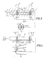
- FIG. 3 illustrates the projectile 10 with the sensor device 12 in a field 18, wherein the projectile 10 carries out a pendulum movement indicated by the arcuate double arrow 20.
- a sinusoidal voltage U 1 is generated in the sensor coil S1, for example, and a sinusoidal voltage U 2 phase-shifted by 180 ° in the oppositely wound sensor coil S2.
- the resulting voltage U R 0.
- FIG. 4 shows the projectile 10 with the sensor device 12 approaching a target 22 to be controlled.
- the sensor coil S1 has a smaller distance from the target 22 than the sensor coil S2, so that a voltage U 1 is induced in the sensor coil S1 is greater than the oppositely polarized due to the opposite Wickelsinnes 16 voltage U 2 , so that as a result of the series connection of the two sensor coils S1 and S2, a resultant voltage U R ⁇ 0 results.
- Figure 5 illustrates a projectile 10 with a sensor device 12 during the flyby at a target 26.
- the target 26 at A in front of the projectile, in the position D laterally querab from the projectile and in the position C behind the projectile.
- the sensor coil S1 is closer to the target 26 than the sensor coil S2, so that in the sensor coil S1, a voltage U 1 and in the sensor coil S2, a voltage U 2 of opposite polarity is generated, whereby U 1 due to the shorter distance to the target 26 is greater than the voltage U 2 .
- the resulting voltage is indicated in this position A in the U (t) diagram with U R, A.
- the temporal course of the resulting voltage U R of the sensor device 10 can thus be used in a noise-compensated manner to determine the respective scenario of the projectile 10 with simple means comparatively easily.
Landscapes
- Engineering & Computer Science (AREA)
- General Engineering & Computer Science (AREA)
- Measurement Of Length, Angles, Or The Like Using Electric Or Magnetic Means (AREA)
- Transmission And Conversion Of Sensor Element Output (AREA)
Applications Claiming Priority (1)
| Application Number | Priority Date | Filing Date | Title |
|---|---|---|---|
| DE200610028598 DE102006028598B4 (de) | 2006-06-22 | 2006-06-22 | Sensoreinrichtung insbesondere für ein Geschoss |
Publications (2)
| Publication Number | Publication Date |
|---|---|
| EP1892496A2 true EP1892496A2 (fr) | 2008-02-27 |
| EP1892496A3 EP1892496A3 (fr) | 2008-06-04 |
Family
ID=38805886
Family Applications (1)
| Application Number | Title | Priority Date | Filing Date |
|---|---|---|---|
| EP07011080A Withdrawn EP1892496A3 (fr) | 2006-06-22 | 2007-06-06 | Dispositif de capteur, en particulier pour un projectile |
Country Status (2)
| Country | Link |
|---|---|
| EP (1) | EP1892496A3 (fr) |
| DE (1) | DE102006028598B4 (fr) |
Citations (1)
| Publication number | Priority date | Publication date | Assignee | Title |
|---|---|---|---|---|
| US2976483A (en) | 1956-11-30 | 1961-03-21 | William H Moore | Gradiometer for underwater missile warhead |
Family Cites Families (9)
| Publication number | Priority date | Publication date | Assignee | Title |
|---|---|---|---|---|
| US2892403A (en) * | 1941-09-18 | 1959-06-30 | James B Glennon | Mine firing mechanism |
| US3850100A (en) * | 1943-08-28 | 1974-11-26 | Us Navy | Mine firing control system |
| US3653351A (en) * | 1969-07-16 | 1972-04-04 | Us Navy | Magnetic detector |
| US4164905A (en) * | 1971-12-22 | 1979-08-21 | The United States Of America As Represented By The Secretary Of The Army | Lumped neutralization coil arrangement for inductance fuze |
| DE2546659C2 (de) * | 1975-10-17 | 1983-08-25 | Förenade Fabriksverken, 63187 Eskilstuna | Zündvorrichtung für eine Magnetmine |
| FR2354534A1 (fr) * | 1976-06-11 | 1978-01-06 | Serat | Perfectionnements aux allumeurs a influences sismique et magnetique |
| CH639479A5 (fr) * | 1980-11-17 | 1983-11-15 | Perret Jean | Detecteur inductif de proximite et son utilisation. |
| DE3211666A1 (de) * | 1982-03-30 | 1990-06-07 | Telefunken Systemtechnik | Induktiver annaeherungszuender |
| DE3339066A1 (de) * | 1983-10-28 | 1985-05-09 | Diehl GmbH & Co, 8500 Nürnberg | Magnetfeldsensor |
-
2006
- 2006-06-22 DE DE200610028598 patent/DE102006028598B4/de not_active Expired - Fee Related
-
2007
- 2007-06-06 EP EP07011080A patent/EP1892496A3/fr not_active Withdrawn
Patent Citations (1)
| Publication number | Priority date | Publication date | Assignee | Title |
|---|---|---|---|---|
| US2976483A (en) | 1956-11-30 | 1961-03-21 | William H Moore | Gradiometer for underwater missile warhead |
Also Published As
| Publication number | Publication date |
|---|---|
| DE102006028598B4 (de) | 2008-04-10 |
| DE102006028598A1 (de) | 2008-01-10 |
| EP1892496A3 (fr) | 2008-06-04 |
Similar Documents
| Publication | Publication Date | Title |
|---|---|---|
| EP3256828B1 (fr) | Dispositif pour mesurer une force ou un couple avec de moins trois sondes de champ magnétiques | |
| DE69936138T2 (de) | Magnetischer kraftsensor und verfahren zu dessen herstellung | |
| EP2965043B1 (fr) | Codeur linéaire ou rotatif magnétique | |
| DE102014219336B3 (de) | Verfahren und Anordnung zur Messung einer Kraft oder eines Momentes mit mehreren Magnetfeldsensoren | |
| EP0979988B1 (fr) | Procédé de mesure des mouvements linéaires entre aimants et capteurs | |
| DE102016002420B4 (de) | Verfahren zur Bestimmung der Position eines Magneten relativ zu einer Sensorzelle | |
| DE102007039050A1 (de) | Linearsegment- oder Umdrehungszähler mit einem ferromagnetischen Element | |
| DE102010056271A1 (de) | Sensoranordnung zur Erfassung sowohl der Axial- als auch der Drehstellung einer in Längsrichtung verschieblichen und drehbaren Welle | |
| DE102015122154A1 (de) | Vorrichtung zur Feststellung externer magnetischer Streufelder auf einen Magnetfeldsensor | |
| DE102015200268B3 (de) | Anordnung zur Messung einer Kraft oder eines Momentes mit einem Magnetfeldsensor und mit einem Magnetfeldleitelement | |
| DE102017222677A1 (de) | Sensoreinrichtung | |
| DE102009047222A1 (de) | Sensoranordnung zum Ermitteln eines Drehmoments und zur Indexerkennung | |
| DE102015202239B3 (de) | Anordnung zur Messung einer Kraft oder eines Momentes mit mindestens vier Magnetfeldsensoren | |
| DE102010010388A1 (de) | Magnetverbund | |
| DE102013211000A1 (de) | Anordnungen und Verfahren zum Messen einer Kraft oder eines Momentes an einem Maschinenelement | |
| DE202015105090U1 (de) | Redundanter Drehmomentsensor - Multiple Bandanordnung | |
| DE112009000497T5 (de) | Ursprungspositions-Signaldetektor | |
| DE102015209286A1 (de) | Anordnung und Verfahren zum Messen einer Kraft oder eines Momentes mit mindestens zwei beabstandeten Magnetfeldsensoren | |
| DE102015102337A1 (de) | Redundanter Drehmomentsensor - Multiple Bandanordnung | |
| DE102007042920A1 (de) | Sensoranordnung für eine in einem Magnetlager gelagerte Welle | |
| DE102011083948A1 (de) | Sensoranordnung | |
| WO2020224712A1 (fr) | Dispositif de mesure d'un couple agissant sur un arbre de direction d'un véhicule automobile et procédé de contrôle du dispositif | |
| DE102008062864A1 (de) | Wegsensoranordnung | |
| EP1847810A1 (fr) | Procédé et dispositif destinés à la détection de position | |
| DE102013219079A1 (de) | Bauteil, Vorrichtung und Verfahren zur Messung einer Materialspannung mittels Magnetostriktion |
Legal Events
| Date | Code | Title | Description |
|---|---|---|---|
| PUAI | Public reference made under article 153(3) epc to a published international application that has entered the european phase |
Free format text: ORIGINAL CODE: 0009012 |
|
| AK | Designated contracting states |
Kind code of ref document: A2 Designated state(s): AT BE BG CH CY CZ DE DK EE ES FI FR GB GR HU IE IS IT LI LT LU LV MC MT NL PL PT RO SE SI SK TR |
|
| AX | Request for extension of the european patent |
Extension state: AL BA HR MK YU |
|
| 17P | Request for examination filed |
Effective date: 20080202 |
|
| PUAL | Search report despatched |
Free format text: ORIGINAL CODE: 0009013 |
|
| AK | Designated contracting states |
Kind code of ref document: A3 Designated state(s): AT BE BG CH CY CZ DE DK EE ES FI FR GB GR HU IE IS IT LI LT LU LV MC MT NL PL PT RO SE SI SK TR |
|
| AX | Request for extension of the european patent |
Extension state: AL BA HR MK RS |
|
| 17Q | First examination report despatched |
Effective date: 20090113 |
|
| AKX | Designation fees paid |
Designated state(s): AT BE BG CH CY CZ DE DK EE ES FI FR GB GR HU IE IS IT LI LT LU LV MC MT NL PL PT RO SE SI SK TR |
|
| GRAP | Despatch of communication of intention to grant a patent |
Free format text: ORIGINAL CODE: EPIDOSNIGR1 |
|
| INTG | Intention to grant announced |
Effective date: 20130604 |
|
| STAA | Information on the status of an ep patent application or granted ep patent |
Free format text: STATUS: THE APPLICATION IS DEEMED TO BE WITHDRAWN |
|
| 18D | Application deemed to be withdrawn |
Effective date: 20131015 |