EP1892407B1 - Injecteur de carburant doté d'un mouvement de levé conduit amélioré de l'organe de fermeture - Google Patents
Injecteur de carburant doté d'un mouvement de levé conduit amélioré de l'organe de fermeture Download PDFInfo
- Publication number
- EP1892407B1 EP1892407B1 EP07111701A EP07111701A EP1892407B1 EP 1892407 B1 EP1892407 B1 EP 1892407B1 EP 07111701 A EP07111701 A EP 07111701A EP 07111701 A EP07111701 A EP 07111701A EP 1892407 B1 EP1892407 B1 EP 1892407B1
- Authority
- EP
- European Patent Office
- Prior art keywords
- spring
- sections
- fuel injector
- ring
- spring element
- Prior art date
- Legal status (The legal status is an assumption and is not a legal conclusion. Google has not performed a legal analysis and makes no representation as to the accuracy of the status listed.)
- Not-in-force
Links
- 239000000446 fuel Substances 0.000 title claims abstract description 28
- 238000005452 bending Methods 0.000 claims description 23
- 230000006835 compression Effects 0.000 claims description 15
- 238000007906 compression Methods 0.000 claims description 15
- 238000002485 combustion reaction Methods 0.000 claims description 10
- 238000004080 punching Methods 0.000 claims description 3
- 230000007704 transition Effects 0.000 claims description 3
- 238000000034 method Methods 0.000 claims 1
- 230000036316 preload Effects 0.000 claims 1
- 238000002347 injection Methods 0.000 abstract 1
- 239000007924 injection Substances 0.000 abstract 1
- 239000000463 material Substances 0.000 description 8
- 125000006850 spacer group Chemical group 0.000 description 6
- 238000004519 manufacturing process Methods 0.000 description 2
- 239000007858 starting material Substances 0.000 description 2
- 229910000639 Spring steel Inorganic materials 0.000 description 1
- 230000001427 coherent effect Effects 0.000 description 1
- 230000009849 deactivation Effects 0.000 description 1
- 230000001419 dependent effect Effects 0.000 description 1
- 238000011161 development Methods 0.000 description 1
- 230000018109 developmental process Effects 0.000 description 1
- 230000000694 effects Effects 0.000 description 1
- 238000005516 engineering process Methods 0.000 description 1
- 238000010438 heat treatment Methods 0.000 description 1
- 239000002184 metal Substances 0.000 description 1
- 230000005855 radiation Effects 0.000 description 1
- 230000000284 resting effect Effects 0.000 description 1
- 238000007789 sealing Methods 0.000 description 1
- 238000007493 shaping process Methods 0.000 description 1
Images



Classifications
-
- F—MECHANICAL ENGINEERING; LIGHTING; HEATING; WEAPONS; BLASTING
- F02—COMBUSTION ENGINES; HOT-GAS OR COMBUSTION-PRODUCT ENGINE PLANTS
- F02M—SUPPLYING COMBUSTION ENGINES IN GENERAL WITH COMBUSTIBLE MIXTURES OR CONSTITUENTS THEREOF
- F02M63/00—Other fuel-injection apparatus having pertinent characteristics not provided for in groups F02M39/00 - F02M57/00 or F02M67/00; Details, component parts, or accessories of fuel-injection apparatus, not provided for in, or of interest apart from, the apparatus of groups F02M39/00 - F02M61/00 or F02M67/00; Combination of fuel pump with other devices, e.g. lubricating oil pump
- F02M63/0012—Valves
- F02M63/0014—Valves characterised by the valve actuating means
- F02M63/0015—Valves characterised by the valve actuating means electrical, e.g. using solenoid
- F02M63/0026—Valves characterised by the valve actuating means electrical, e.g. using solenoid using piezoelectric or magnetostrictive actuators
-
- F—MECHANICAL ENGINEERING; LIGHTING; HEATING; WEAPONS; BLASTING
- F02—COMBUSTION ENGINES; HOT-GAS OR COMBUSTION-PRODUCT ENGINE PLANTS
- F02M—SUPPLYING COMBUSTION ENGINES IN GENERAL WITH COMBUSTIBLE MIXTURES OR CONSTITUENTS THEREOF
- F02M47/00—Fuel-injection apparatus operated cyclically with fuel-injection valves actuated by fluid pressure
- F02M47/02—Fuel-injection apparatus operated cyclically with fuel-injection valves actuated by fluid pressure of accumulator-injector type, i.e. having fuel pressure of accumulator tending to open, and fuel pressure in other chamber tending to close, injection valves and having means for periodically releasing that closing pressure
- F02M47/027—Electrically actuated valves draining the chamber to release the closing pressure
-
- F—MECHANICAL ENGINEERING; LIGHTING; HEATING; WEAPONS; BLASTING
- F02—COMBUSTION ENGINES; HOT-GAS OR COMBUSTION-PRODUCT ENGINE PLANTS
- F02M—SUPPLYING COMBUSTION ENGINES IN GENERAL WITH COMBUSTIBLE MIXTURES OR CONSTITUENTS THEREOF
- F02M63/00—Other fuel-injection apparatus having pertinent characteristics not provided for in groups F02M39/00 - F02M57/00 or F02M67/00; Details, component parts, or accessories of fuel-injection apparatus, not provided for in, or of interest apart from, the apparatus of groups F02M39/00 - F02M61/00 or F02M67/00; Combination of fuel pump with other devices, e.g. lubricating oil pump
- F02M63/0012—Valves
- F02M63/0031—Valves characterized by the type of valves, e.g. special valve member details, valve seat details, valve housing details
-
- F—MECHANICAL ENGINEERING; LIGHTING; HEATING; WEAPONS; BLASTING
- F02—COMBUSTION ENGINES; HOT-GAS OR COMBUSTION-PRODUCT ENGINE PLANTS
- F02M—SUPPLYING COMBUSTION ENGINES IN GENERAL WITH COMBUSTIBLE MIXTURES OR CONSTITUENTS THEREOF
- F02M2200/00—Details of fuel-injection apparatus, not otherwise provided for
- F02M2200/26—Fuel-injection apparatus with elastically deformable elements other than coil springs
-
- F—MECHANICAL ENGINEERING; LIGHTING; HEATING; WEAPONS; BLASTING
- F02—COMBUSTION ENGINES; HOT-GAS OR COMBUSTION-PRODUCT ENGINE PLANTS
- F02M—SUPPLYING COMBUSTION ENGINES IN GENERAL WITH COMBUSTIBLE MIXTURES OR CONSTITUENTS THEREOF
- F02M2547/00—Special features for fuel-injection valves actuated by fluid pressure
- F02M2547/001—Control chambers formed by movable sleeves
Definitions
- the present invention relates to a fuel injector for injecting fuel into a combustion chamber of an internal combustion engine for a motor vehicle according to the closer defined in the preamble of patent claim 1, such as in the WO 2005/085624 A or DE 103 35 22 A1 shown.
- a fuel injector for injecting fuel into a combustion chamber of an internal combustion engine having a valve control plate adjacent to a throttle plate is known.
- a valve closing member is provided in the valve control plate, which is biased by a spring element against a valve seat in the valve control plate in a closed position.
- the spring element is located on the part of the valve closure member on a spring collar, which is integrally formed on the valve closure member.
- the valve closure member is rotationally symmetrical, wherein the spring element designed as a spiral compression spring is arranged concentrically around the valve closure member around and exerts a compressive force between the spring collar and the throttle plate.
- the valve closing member is controlled by means of a piezoelectric actuator by the actuator either lifts the valve closure member from the valve seat, so that the pressure in the valve control chamber above the nozzle needles increases to rail pressure and moves the nozzle needle in the closed position.
- the valve closure member performs a lifting movement in a movement axis, wherein the valve closure member is guided axially and self-centering only by the valve seat in the valve control plate.
- the invention includes the technical teaching that the spring element has a plurality of circumferentially distributed flexurally elastic spring clip, which extend between the spring collar of the valve closure member and the throttle plate, wherein the flexurally elastic spring clips spring in a compression of the spring element laterally to achieve a compression spring action.
- the invention is based on the idea to provide a spring element which can be used as a compression spring, and allows a lateral force-free compression over the compression travel, to avoid tilting of the valve closure member. Due to the rotationally symmetrical design of the spring element according to the invention concentrically around the valve closure member, distributed over the circumference transverse force components cancel each other in such a way that a force is introduced exclusively in the movement axis on the valve closure member.
- the spring element has symmetrically distributed around the circumference flexurally elastic spring clip, which bend elastically upon compression of the spring element.
- the bending movement of the flexible elastic spring clip takes place in the lateral direction, which means that the spring clips either spring in the tangential direction within the enveloping body of the spring element or alternatively deflect radially directed outwards.
- the resulting spring force results from the sum of the individual spring forces of the flexurally elastic spring clips.
- the spring element according to the present invention without structural changes to the valve closing member, on the valve control plate or even on the throttle plate are replaced by the compression coil spring according to the prior art, resulting in the desired success of a lateral force-free characteristic of the deflection of the spring element.
- the spring element is formed from a spring wire which is bent in a meandering manner and extends in a basket-like manner around the valve closure member, wherein meandering portions extending approximately parallel to the movement axis form the flexurally elastic spring clips.
- a simple structural design of the spring element results, in which a spring wire with a round or rectangular or square cross-section is bent into a meandering structure, which is subsequently brought into a ring structure to form a circular spring cage , The ends of the spring wire can be welded or soldered together to prevent expansion of the basket-like spring element in the circumferential direction.
- the bending wire spring thus has outer dimensions with a given height and an inner diameter.
- the inner diameter is based on the diameter of the valve closure member, and can also be guided by this.
- a curvature having a radius of curvature (R) is introduced into the meandering sections forming the flexurally elastic spring clips, as a result of which lateral deflection is predeterminable.
- the flexurally elastic spring clip forming meander sections and extending substantially parallel to the axis of movement of the valve closure member.
- the structure of the spring wire slightly deviates from the meander shape, since the introduced curvature is required to specify the lateral deflection.
- the direction of the curvature of the meandering sections lies either in the tangential direction within the enveloping body of the spring cage, wherein a radially outwardly oriented bending direction is also possible, in which the curvature is introduced into the meandering section.
- the spring wire between the bending elastic spring clip forming meander sections Aufstandsabroughe with which the spring wire rests against the spring collar of the valve closure member and the throttle plate.
- the spring wire has a total of eight bending elastic spring clip forming meander sections, which in pairs form a meander loop, wherein the meander loops are arranged distributed approximately 90 ° to each other on the circumference of the spring element.
- the spring wire initially forms a cylindrical basic shape within a tubular enveloping body. Starting with a part of the Aufstanzabiteses this extends in the horizontal and is subsequently angled approximately 90 ° and extends in a vertical direction parallel to the axis of movement.
- the vertical meander sections which form the bending-elastic spring clips, do not form a straight line, but have a curvature with the radius of curvature (R).
- R radius of curvature
- the respective uprising sections occupy an angle section of 45 °, so that after reaching the angle section of the spring wire is again about 90 ° directed downwards angled and merges into the meander section, which forms the next flexible elastic spring clip.
- the structure is repeated four times evenly distributed on the circumference, so that the spring element has four meander loops, which are each offset by 90 ° to each other.
- the spring element is formed from a cylindrical pipe section, and the pipe section has recesses formed in the lateral surface, so that the remaining in the lateral surface areas between the recesses form the flexible elastic spring clip.
- the goal is achieved that a transverse force free bow spring sleeve is formed.
- the recesses are cut out, for example, by means of laser beam cutting from the lateral surface of the pipe section.
- the remaining structure has areas between the recesses forming the flexurally elastic spring clips. In this case, the regions remaining between the recesses and the tube section which delimit longitudinal side end faces form respective contact rings, via which the spring element rests against the spring collar and against the throttle plate.
- the flexurally elastic spring clips which are formed from the remaining areas between the recesses, go on the same material in the uprising rings.
- the flexible elastic spring clips have a curvature with a radius of curvature (R), whereby a lateral deflection is predetermined.
- the Spring clips between the backbone rings, prior to transition into the region of curvature, have non-curved guide portions extending approximately perpendicularly from the backbone rings to guide the spring member concentrically on the valve closure member.
- the spring element may comprise a total of 8 spring clips whose curvature is alternately formed in the lateral direction to provide a torsion-free compression of the spring element.
- the bow spring sleeve forming the spring element has eight flexible elastic spring clips, whereby a different number of spring clips can also be provided.
- the spring element is formed from a producible by punching and bending spring cage, wherein the spring cage has a plurality of ring sections which are interconnected via spring bar sections, so that the ring sections and the spring bar sections are formed integrally.
- the spring cage consists of a central annular portion of which three spring bar sections in angular segments of 120 ° equally spaced from each other radially outwardly, on each of which two ring sections are formed radially outwardly, between each of which a further spring bar section is arranged.
- the initial shape of the spring element is formed, which can be stamped from a sheet material from the tape.
- the strip material may comprise a spring steel, which may be subjected to a heat treatment as needed.
- the spring element is initially in a flat initial state, and around the central ring portion extend around the spring bar sections in turn, which in each case again followed by a ring portion, and further radially outwardly a respective further spring land portion is formed, which ends in a last ring portion.
- This geometry is repeated three times distributed on the circumference of the central ring portion, so that the total of seven ring sections and six spring bar sections form a unitary coherent element.
- the ring sections each have axes of symmetry, and the ring sections by means of elastic bending of the spring bar sections can be brought over one another such that the axes of symmetry of the ring sections are aligned, whereby the spring cage is sentbar. Due to this geometry results in a virtually transverse force-free spring element, which is comparable to a bow spring.
- the spring rate can be adapted to the spring rate of the helical compression spring due to appropriately selected material properties and the material thickness.
- the bow spring can be designed in two layers, with several layers are possible in principle.
- the priority in the refilling of the valve and control chamber within the valve control plate or above the nozzle needle is directed to the control room.
- spacers are integrated at the central ring section. They also minimize the deactivation of the valve pin.
- a spring element wherein the aligned ring sections form an upper contact ring for abutment with the spring collar and a lower contact ring to rest against the throttle plate, wherein equally spaced between the upper and lower ring an intermediate ring is formed, and between the riot ring and the intermediate ring each have three spring bar sections which form the flexible elastic spring clip.
- three spring bar sections each having a curvature of 180 ° extend equidistantly on a circumference of 120 °.
- the angular positions of the three spring bar sections between the lower ring section and the middle ring section in relation to the middle ring section and the upper ring section are each offset by 60 °.
- a spring element can be formed, which allows a practically transverse force-free compressing, wherein the compression causes an elastic bend within the spring bar sections, and the spring forces of the respective spring bar sections add between equal planes, wherein the spring travel between the lowermost ring section and the middle Ring section and the middle ring section and the upper ring section added.
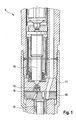
- FIG. 1 shows a fuel injector 1 for injecting fuel into a combustion chamber of an internal combustion engine in a cross-sectional view.
- the view shows a section of the fuel injector 1 in the region of a throttle plate 10, which adjoins a valve control plate 11.
- a valve closing member 13 is received with an integrally formed spring collar 14 for controlling the closing movement of a nozzle needle 12, wherein the valve closing member 13 can move in the movement axis 15 liftable up and down.
- the valve closing member 13 In an upward position, the valve closing member 13 is in a closed position, wherein within the valve control plate 11, a valve seat is introduced, against which the valve closing member 13 is biased by a spring member 16 in a sealing seat.
- FIG. 2 shows a first embodiment of the spring element 16, wherein the cutout with seat of the valve closing member 13 from FIG. 1 is shown in enlarged form.
- both the valve control plate 11, which above the Throttle plate 10 is shown, wherein a pressure channel is directed downward in the throttle plate 10 is inserted below the valve closure member 13.
- the valve closure member 13 includes a molded spring collar 14 against which the spring member 16 is supported to bias the valve closure member 13 against the throttle plate 10.
- the spring element 16 thus extends between the throttle plate 10 and the spring collar 14.
- the vertical portions of the spring element 16 are formed from flexurally elastic spring clips 17, the spring element 16 comprises a total of eight flexible elastic spring clip 17, but in the graph in FIG FIG. 2 only four spring clips 17 are shown.
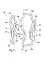
- FIG. 3 shows a perspective view of an embodiment of the spring element 16 according to FIG. 2 ,
- the spring element 16 is formed from a spring wire 18, which is bent meander-shaped and forms a kind of spring cage. Parallel to the movement axis 15, the flexible elastic spring clips 17a to 17h extend, wherein the flexible elastic spring clips have a radius of curvature R.
- the radius of curvature R is formed in the bending elastic spring clips 17 alternately within the tangential direction in the lateral surface of the basket-like spring element 16 to specify a lateral deflection.
- the contact portions 19b, 19d, 19f and 19h form the upper end side of the spring element 16, which abut against the spring collar on the valve closure member.
- a respective guide portion is formed in the basket-like spring member 16 to arrange the spring member 16 concentrically around the valve-closing member, in each of which a guide portion is formed.
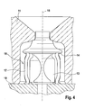
- FIG. 4 another embodiment of the spring element 16 is shown, which the valve closing member 13 against the valve control plate 11 in the axis of movement 15 vertically upwardly supported.
- the spring element 16 adjoins the throttle plate 10.
- the spring element 16 comprises spring clips 17, which extend between the spring collar 14 on the valve closing member 13 and the throttle plate 10.
- FIG. 5 shows a perspective view of the spring element 16 according to the second embodiment FIG. 4 .
- the spring element 16 is formed from a cylindrical tube section, the tube section having recesses formed in the lateral surface, so that the areas remaining in the lateral surface between the recesses form the flexurally elastic spring clips 17a to 17h. Between the recesses and the pipe section longitudinally delimiting end surfaces remaining areas form respective uprising rings 21a and 21b, the uprising ring 21 abuts against the spring collar and the uprising ring 21b against the throttle plate.
- FIG. 6 shows the spring element 16 according to FIG. 5 which is formed from a cylindrical pipe section.
- the hatched areas 20a, 20b and 20c show the respective recesses from the lateral surface of the cylindrical tube section, which are separated out of the cylindrical tube section, for example by means of laser radiation, so that the areas between the recesses 20a, 20b and 20c remain and the flexurally elastic spring clips 17a to 17d form.
- the laser cut is guided in such a way that the flexurally elastic spring clips 17 initially merge into guide regions 22 before they open in the same way and in one piece into the contact ring 21a and 21b.
- a cylindrical tube section is selected as the starting material, whereby a high flexibility for shaping the spring element is provided by the flexible laser cut for cutting out the cutouts 20a, 20b and 20c.
- a total of eight recesses 20 are cut out between the respective spring clips, which due to the view of the spring element 16 in FIG. 6 only three recesses can be displayed.
- FIG. 7 shows a further embodiment of the spring element 16 which extends between the throttle plate 10 and the spring collar 14, which is integrally formed on the valve closure member 13. Also in this embodiment, the spring member 16 biases the valve closing member 13 against a valve seat formed inside the valve control plate.
- the spring element 16 is formed according to this embodiment of a punching and bending technology produced strip material.
- the spring element 16 forms in the finished formed state, a spring cage, which consists of a plurality of ring sections 23a - 23g, which are connected to each other via spring web sections 24a - 24f, so that the ring sections 23 and the spring bar sections 24 as a whole, ie of the same material and of a flat correspondingly shaped Sheet metal are formed.
- the spring element comprises a central ring portion 23a.
- three spring sections 24a, 24b and 24c extend around this in angular segments of 120 °.
- the spring bar sections 24a to 24c extend radially outward, and open into three further ring sections 23b, 23c and 23d respectively.
- At the ring sections 23b, 23c and 23d in turn extend radially outwardly directed three further spring bar sections 24d, 24e and 24f.
- On the outside of the spring bar sections 24d to 24f three further ring sections 23 e, 23 and 23g are formed in each case.
- the spring bar portion 24a is bent 180 ° down.
- the ring sections 23 comprise respective axes of symmetry 25, wherein now the axis of symmetry 25 of the central ring section 23a is aligned with the axis of symmetry 25 of the ring section 23b.
- the subsequent bending operations are carried out in the same way, so that the respective axes of symmetry 25 of all ring sections 23 are brought into alignment.
- the production of the basket-like spring element 16 comprises six bending operations in six steps.
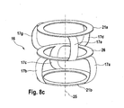
- FIG. 8c a basket-like spring element 16, as this in FIG. 8c is shown.
- an intermediate ring 26 is located, which is formed by design due to the bending operations described above.
- the spring bar sections 24a to 24f form the spring clips 17a to 17f.
- a corresponding assignment can be taken from the respective bending directions.
- the spring clips 17a-17f extend only between the uprising rings 21a and 21b on the upper and lower side and the intermediate ring 26. This ensures that the lateral deflection of the spring clip 17 due to compression of the spring element 16 have only a limited radial deflection, to be integrated into the limited space within the valve control plate.
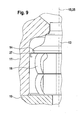
- FIG. 9 is a spring element 16 according to the embodiment of FIGS. 7 to 8c shown.
- the spring element 16 is shown in the installed state within the valve control plate 11, and extends concentrically to the valve closing member 13 between the spring collar 14 and the throttle plate 10. According to this in FIG. 9
- the spring element 16 has a spacer 27, which serves for the lateral guidance of the spring element 16 within the inner wall of the valve control plate 11.
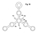
- FIG. 10 shows the stamped on the starting material of the spring element 16 integrally formed spacers 27a, 27b and 27c. These are each arranged at 60 ° to the spring bar sections 24a, 24b and 24c around the central ring portion 23a around.
- the spacers 27 are not bent technically deformed so that they remain in the plane of the ring portion 23 a. This ensures that the spring element 16 and at the same time the valve closing member 13 is guided within the bore in the valve control plate 11 concentric with the axis of movement 15.
- the invention is not limited in its execution to the above-mentioned preferred embodiment.
Landscapes
- Engineering & Computer Science (AREA)
- Chemical & Material Sciences (AREA)
- Combustion & Propulsion (AREA)
- Mechanical Engineering (AREA)
- General Engineering & Computer Science (AREA)
- Physics & Mathematics (AREA)
- Fluid Mechanics (AREA)
- Fuel-Injection Apparatus (AREA)
Claims (14)
- Injecteur de carburant (1) pour l'injection de carburant dans une chambre de combustion d'un moteur à combustion interne, comprenant une plaque de commande de soupape (11) adjacente à une plaque d'étranglement (10), dans laquelle, pour la commande du mouvement de fermeture d'une aiguille d'injecteur (12), un organe de fermeture de soupape (13) avec une collerette élastique moulée (14) est reçu avec une course déplaçable dans un axe de déplacement (15), un élément de ressort (16) étant prévu entre la collerette élastique (14) et la plaque d'étranglement (10), lequel est disposé concentriquement autour de l'organe de fermeture de soupape (13), afin de précontraindre l'organe de fermeture de soupape (13) dans une position de fermeture,
caractérisé en ce que l'élément de ressort (16) présente plusieurs étriers à ressort (17) élastiquement flexibles répartis sur la périphérie, qui s'étendent entre la collerette élastique (14) de l'organe de fermeture de soupape (13) et la plaque d'étranglement (10), les étriers à ressort (17) élastiquement flexibles, en cas de compression de l'élément de ressort (16), se comprimant latéralement afin de produire un effet de ressort de pression. - Injecteur de carburant (1) selon la revendication 1,
caractérisé en ce que l'élément de ressort (16) est formé d'un fil à ressort (18) qui est courbé en méandres et qui s'étend en forme de panier autour de l'organe de fermeture de soupape (13), des portions en méandre qui s'étendent approximativement parallèlement à l'axe de déplacement (15) formant les étriers à ressort (17a-17h) élastiquement flexibles. - Injecteur de carburant (1) selon la revendication 2,
caractérisé en ce que dans les portions en méandres formant les étriers à ressort (17) élastiquement flexibles est pratiquée une courbure ayant un rayon de courbure (R), de sorte qu'une compression de ressort latérale puisse être obtenue. - Injecteur de carburant (1) selon la revendication 2 ou 3,
caractérisé en ce que le fil à ressort (18) présente entre les portions en méandres formant les étriers à ressort (17) élastiquement flexibles, des portions de support (19a - 19i) avec lesquelles le fil à ressort (18) s'applique contre la collerette élastique (14) de l'organe de fermeture de soupape (13) et contre la plaque d'étranglement (10). - Injecteur de carburant (1) selon les revendications 2 à 4,
caractérisé en ce que le fil à ressort (18) présente dans l'ensemble huit portions en méandres formant les étriers à ressort (17a-17h) élastiquement flexibles, lesquelles forment à chaque fois, par paire, une boucle en méandres, les boucles en méandres étant disposées de manière décalées les unes par rapport aux autres de 90° de manière répartie sur la périphérie de l'élément de ressort (16). - Injecteur de carburant (1) selon la revendication 1,
caractérisé en ce que l'élément de ressort (16) est formé d'une portion tubulaire cylindrique et la portion tubulaire présente des évidements (20a, 20b, 20c) réalisés dans la surface d'enveloppe, de sorte que les régions restant dans la surface d'enveloppe forment entre les évidements (20a, 20b, 20c) les étriers à ressort (17a-17h) élastiquement flexibles. - Injecteur de carburant (1) selon la revendication 6,
caractérisé en ce que les régions subsistant entre les évidements (20a, 20b, 20c) et les surfaces d'extrémité limitant du côté longitudinal la portion tubulaire forment à chaque fois des bagues de support (21a, 21b) par le biais desquelles l'élément de ressort (16) s'applique contre la collerette élastique (14) et contre la plaque d'étranglement (10). - Injecteur de carburant (1) selon la revendication 6 ou 7,
caractérisé en ce que les étriers à ressort (17a-17h) présentent une courbure avec un rayon de courbure (R), de sorte qu'une compression de ressort latérale puisse être prédéfinie. - Injecteur de carburant (1) selon la revendication 7 ou 8, caractérisé en ce que les étriers à ressort (17a-17h) présentent entre les bagues de support (21a, 21b) et avant la transition dans la région de la courbure des régions de guidage (22) non courbées, s'étendant depuis les bagues de support (21a, 21b) approximativement à angle droit, afin de guider l'élément de ressort (16) concentriquement sur l'organe de fermeture de soupape (13).
- Injecteur de carburant (1) selon l'une quelconque des revendications 6 à 9,
caractérisé en ce que l'élément de ressort (16) comprend au total huit étriers à ressort (17) dont la courbure dans la direction latérale est inversée afin de produire une compression sans torsion de l'élément de ressort (16). - Injecteur de carburant (1) selon la revendication 1,
caractérisé en ce que l'élément de ressort (16) est formé d'un panier à ressort pouvant être fabriqué par des opérations d'estampage et de flexion, le panier à ressort présentant plusieurs portions annulaires (23a - 23g) qui sont connectées les unes aux autres par le biais de portions de nervures à ressort (24a - 24f) de sorte que les portions annulaires (23a - 23g) et les portions de nervures à ressort (24a - 24f) soient réalisées dans l'ensemble d'une seule pièce. - Injecteur de carburant (1) selon la revendication 11,
caractérisé en ce que le panier à ressort est formé d'une portion annulaire centrale (23a) de laquelle s'étendent, radialement vers l'extérieur, trois portions de nervures à ressort (24a - 24c) de manière équidistante suivant des segments angulaires de 120°, sur lesquelles sont moulées à chaque fois deux autres portions annulaires (23b - 23g) orientées radialement vers l'extérieur, une autre portion de nervure à ressort (24d - 24f) étant à chaque fois disposée entre les portions annulaires intérieures (23b - 23c) et entre les portions annulaire extérieures (23e - 23g). - Injecteur de carburant (1) selon la revendication 11 ou 12, caractérisé en ce que les portions annulaires (23a - 23g) présentent à chaque fois des axes de symétrie (25) et les portions annulaires (23a - 23g) peuvent être amenées au moyen d'une flexion élastique des portions de nervure à ressort (24a - 24f) les unes sur les autres de telle sorte que les axes de symétrie (25) des portions annulaires (23a - 23g) soient alignés les uns avec les autres de sorte que l'on puisse former le panier à ressort.
- Injecteur de carburant (1) selon l'une quelconque des revendications 11 à 13, caractérisé en ce que les portions annulaires (23a - 23g) alignées forment une bague de support supérieure (21a) venant en appui contre la collerette élastique (14) et une bague de support inférieure (21b) venant en appui contre la plaque d'étranglement (10), une bague intermédiaire (26) étant formée à égale distance entre la bague de support supérieure et la bague de support inférieure (21a, 21b), et à chaque fois trois portions de nervures à ressort (24a - 24c, 24d - 24f) s'étendant entre les bagues de support (21a, 21b) et la bague intermédiaire (26) et formant les étriers à ressort (17) élastiquement flexibles.
Applications Claiming Priority (1)
| Application Number | Priority Date | Filing Date | Title |
|---|---|---|---|
| DE102006037175A DE102006037175A1 (de) | 2006-08-09 | 2006-08-09 | Kraftstoffinjektor mit verbessert geführter Hubbewegung des Ventilschließgliedes |
Publications (2)
| Publication Number | Publication Date |
|---|---|
| EP1892407A1 EP1892407A1 (fr) | 2008-02-27 |
| EP1892407B1 true EP1892407B1 (fr) | 2009-09-09 |
Family
ID=38792192
Family Applications (1)
| Application Number | Title | Priority Date | Filing Date |
|---|---|---|---|
| EP07111701A Not-in-force EP1892407B1 (fr) | 2006-08-09 | 2007-07-04 | Injecteur de carburant doté d'un mouvement de levé conduit amélioré de l'organe de fermeture |
Country Status (3)
| Country | Link |
|---|---|
| EP (1) | EP1892407B1 (fr) |
| AT (1) | ATE442522T1 (fr) |
| DE (2) | DE102006037175A1 (fr) |
Families Citing this family (1)
| Publication number | Priority date | Publication date | Assignee | Title |
|---|---|---|---|---|
| DE102009046336A1 (de) | 2009-11-03 | 2011-05-05 | Robert Bosch Gmbh | Ventilanordnung eines Kraftstoffinjektors |
Family Cites Families (5)
| Publication number | Priority date | Publication date | Assignee | Title |
|---|---|---|---|---|
| DE10029297A1 (de) * | 2000-06-14 | 2001-10-18 | Bosch Gmbh Robert | Ventil zum Steuern von Flüssigkeiten |
| DE10250720A1 (de) * | 2002-10-31 | 2004-05-13 | Robert Bosch Gmbh | Einspritzventil |
| DE10335211A1 (de) * | 2003-08-01 | 2005-02-17 | Robert Bosch Gmbh | Kraftstoff-Einspritzvorrichtung für eine Brennkraftmaschine |
| DE102004011095A1 (de) * | 2004-03-06 | 2005-09-22 | Robert Bosch Gmbh | Kraftstoffeinspritzventil |
| DE102006009069A1 (de) * | 2006-02-28 | 2007-08-30 | Robert Bosch Gmbh | Brennstoffeinspritzventil |
-
2006
- 2006-08-09 DE DE102006037175A patent/DE102006037175A1/de not_active Withdrawn
-
2007
- 2007-07-04 EP EP07111701A patent/EP1892407B1/fr not_active Not-in-force
- 2007-07-04 AT AT07111701T patent/ATE442522T1/de active
- 2007-07-04 DE DE502007001478T patent/DE502007001478D1/de active Active
Also Published As
| Publication number | Publication date |
|---|---|
| DE502007001478D1 (de) | 2009-10-22 |
| ATE442522T1 (de) | 2009-09-15 |
| DE102006037175A1 (de) | 2008-02-14 |
| EP1892407A1 (fr) | 2008-02-27 |
Similar Documents
| Publication | Publication Date | Title |
|---|---|---|
| EP1490594B1 (fr) | Soupape d'injection de carburant | |
| WO2000079120A1 (fr) | Soupape d'injection de carburant | |
| EP1636486B1 (fr) | Unite actionneur pour soupape d'injection de carburant a commande piezo-electrique | |
| EP2664779B1 (fr) | Soupape pour le dosage de fluide | |
| EP1623468B1 (fr) | Unite actionneur pour soupape d'injection de carburant a commande piezo-electrique | |
| EP1519072B1 (fr) | Ressort tubulaire pour un actionneur | |
| EP1892407B1 (fr) | Injecteur de carburant doté d'un mouvement de levé conduit amélioré de l'organe de fermeture | |
| DE102009001099A1 (de) | Kraftstoffeinspritzventil | |
| DE10055483A1 (de) | Brennstoffeinspritzventil und Verfahren zur Herstellung von Ventilnadeln oder Ventilschließkörpern für Brennstoffeinspritzventile | |
| WO2017005557A1 (fr) | Soupape de gaz | |
| EP1078157A1 (fr) | Soupape d'injection de carburant | |
| DE19958705A1 (de) | Ventil mit verbesserter Anschlaggeometrie | |
| WO2012034837A1 (fr) | Ressort tubulaire destiné à recevoir et précontraindre un actionneur | |
| WO2013098155A1 (fr) | Dispositif à levier et injecteur | |
| DE10063261B4 (de) | Brennstoffeinspritzventil | |
| EP3359805B1 (fr) | Dispositif d'injection de fluide pour moteurs à combustion interne | |
| EP1664524B1 (fr) | Systeme de soupape, notamment soupape d'injection de carburant pour moteur a combustion interne | |
| DE60304442T2 (de) | Messvorrichtung mit Durchfluss-Kalibriereinrichtung sowie Verfahren zur Einstellung der Durchflussmenge der Messvorrichtung | |
| EP1105641B1 (fr) | Soupape d'admission de carburant | |
| EP1508720B1 (fr) | Ressort tubulaire pour actionneur | |
| EP3303817B1 (fr) | Injecteur common rail | |
| DE961231C (de) | Ringplattenventil | |
| DE20218768U1 (de) | Federpaket | |
| DE102016225939A1 (de) | Elektromagnetisch betätigbares Ventil und Verfahren zur Herstellung einer Ventilnadel für ein elektromagnetisch betätigbares Ventil | |
| DE10319586A1 (de) | Aktoreinheit für ein piezogesteuertes Kraftstoffeinspritzventil |
Legal Events
| Date | Code | Title | Description |
|---|---|---|---|
| PUAI | Public reference made under article 153(3) epc to a published international application that has entered the european phase |
Free format text: ORIGINAL CODE: 0009012 |
|
| AK | Designated contracting states |
Kind code of ref document: A1 Designated state(s): AT BE BG CH CY CZ DE DK EE ES FI FR GB GR HU IE IS IT LI LT LU LV MC MT NL PL PT RO SE SI SK TR |
|
| AX | Request for extension of the european patent |
Extension state: AL BA HR MK YU |
|
| 17P | Request for examination filed |
Effective date: 20080827 |
|
| AKX | Designation fees paid |
Designated state(s): AT BE BG CH CY CZ DE DK EE ES FI FR GB GR HU IE IS IT LI LT LU LV MC MT NL PL PT RO SE SI SK TR |
|
| GRAP | Despatch of communication of intention to grant a patent |
Free format text: ORIGINAL CODE: EPIDOSNIGR1 |
|
| GRAS | Grant fee paid |
Free format text: ORIGINAL CODE: EPIDOSNIGR3 |
|
| GRAA | (expected) grant |
Free format text: ORIGINAL CODE: 0009210 |
|
| AK | Designated contracting states |
Kind code of ref document: B1 Designated state(s): AT BE BG CH CY CZ DE DK EE ES FI FR GB GR HU IE IS IT LI LT LU LV MC MT NL PL PT RO SE SI SK TR |
|
| REG | Reference to a national code |
Ref country code: GB Ref legal event code: FG4D Free format text: NOT ENGLISH |
|
| REG | Reference to a national code |
Ref country code: CH Ref legal event code: EP |
|
| REG | Reference to a national code |
Ref country code: IE Ref legal event code: FG4D |
|
| REF | Corresponds to: |
Ref document number: 502007001478 Country of ref document: DE Date of ref document: 20091022 Kind code of ref document: P |
|
| PG25 | Lapsed in a contracting state [announced via postgrant information from national office to epo] |
Ref country code: FI Free format text: LAPSE BECAUSE OF FAILURE TO SUBMIT A TRANSLATION OF THE DESCRIPTION OR TO PAY THE FEE WITHIN THE PRESCRIBED TIME-LIMIT Effective date: 20090909 Ref country code: SE Free format text: LAPSE BECAUSE OF FAILURE TO SUBMIT A TRANSLATION OF THE DESCRIPTION OR TO PAY THE FEE WITHIN THE PRESCRIBED TIME-LIMIT Effective date: 20090909 Ref country code: LT Free format text: LAPSE BECAUSE OF FAILURE TO SUBMIT A TRANSLATION OF THE DESCRIPTION OR TO PAY THE FEE WITHIN THE PRESCRIBED TIME-LIMIT Effective date: 20090909 |
|
| NLV1 | Nl: lapsed or annulled due to failure to fulfill the requirements of art. 29p and 29m of the patents act | ||
| LTIE | Lt: invalidation of european patent or patent extension |
Effective date: 20090909 |
|
| PG25 | Lapsed in a contracting state [announced via postgrant information from national office to epo] |
Ref country code: LV Free format text: LAPSE BECAUSE OF FAILURE TO SUBMIT A TRANSLATION OF THE DESCRIPTION OR TO PAY THE FEE WITHIN THE PRESCRIBED TIME-LIMIT Effective date: 20090909 Ref country code: PL Free format text: LAPSE BECAUSE OF FAILURE TO SUBMIT A TRANSLATION OF THE DESCRIPTION OR TO PAY THE FEE WITHIN THE PRESCRIBED TIME-LIMIT Effective date: 20090909 Ref country code: SI Free format text: LAPSE BECAUSE OF FAILURE TO SUBMIT A TRANSLATION OF THE DESCRIPTION OR TO PAY THE FEE WITHIN THE PRESCRIBED TIME-LIMIT Effective date: 20090909 Ref country code: NL Free format text: LAPSE BECAUSE OF FAILURE TO SUBMIT A TRANSLATION OF THE DESCRIPTION OR TO PAY THE FEE WITHIN THE PRESCRIBED TIME-LIMIT Effective date: 20090909 |
|
| PG25 | Lapsed in a contracting state [announced via postgrant information from national office to epo] |
Ref country code: CY Free format text: LAPSE BECAUSE OF FAILURE TO SUBMIT A TRANSLATION OF THE DESCRIPTION OR TO PAY THE FEE WITHIN THE PRESCRIBED TIME-LIMIT Effective date: 20090909 |
|
| REG | Reference to a national code |
Ref country code: IE Ref legal event code: FD4D |
|
| PG25 | Lapsed in a contracting state [announced via postgrant information from national office to epo] |
Ref country code: EE Free format text: LAPSE BECAUSE OF FAILURE TO SUBMIT A TRANSLATION OF THE DESCRIPTION OR TO PAY THE FEE WITHIN THE PRESCRIBED TIME-LIMIT Effective date: 20090909 Ref country code: ES Free format text: LAPSE BECAUSE OF FAILURE TO SUBMIT A TRANSLATION OF THE DESCRIPTION OR TO PAY THE FEE WITHIN THE PRESCRIBED TIME-LIMIT Effective date: 20091220 Ref country code: RO Free format text: LAPSE BECAUSE OF FAILURE TO SUBMIT A TRANSLATION OF THE DESCRIPTION OR TO PAY THE FEE WITHIN THE PRESCRIBED TIME-LIMIT Effective date: 20090909 Ref country code: IS Free format text: LAPSE BECAUSE OF FAILURE TO SUBMIT A TRANSLATION OF THE DESCRIPTION OR TO PAY THE FEE WITHIN THE PRESCRIBED TIME-LIMIT Effective date: 20100109 Ref country code: IE Free format text: LAPSE BECAUSE OF FAILURE TO SUBMIT A TRANSLATION OF THE DESCRIPTION OR TO PAY THE FEE WITHIN THE PRESCRIBED TIME-LIMIT Effective date: 20090909 Ref country code: PT Free format text: LAPSE BECAUSE OF FAILURE TO SUBMIT A TRANSLATION OF THE DESCRIPTION OR TO PAY THE FEE WITHIN THE PRESCRIBED TIME-LIMIT Effective date: 20100111 Ref country code: CZ Free format text: LAPSE BECAUSE OF FAILURE TO SUBMIT A TRANSLATION OF THE DESCRIPTION OR TO PAY THE FEE WITHIN THE PRESCRIBED TIME-LIMIT Effective date: 20090909 |
|
| PG25 | Lapsed in a contracting state [announced via postgrant information from national office to epo] |
Ref country code: SK Free format text: LAPSE BECAUSE OF FAILURE TO SUBMIT A TRANSLATION OF THE DESCRIPTION OR TO PAY THE FEE WITHIN THE PRESCRIBED TIME-LIMIT Effective date: 20090909 |
|
| PLBE | No opposition filed within time limit |
Free format text: ORIGINAL CODE: 0009261 |
|
| STAA | Information on the status of an ep patent application or granted ep patent |
Free format text: STATUS: NO OPPOSITION FILED WITHIN TIME LIMIT |
|
| PG25 | Lapsed in a contracting state [announced via postgrant information from national office to epo] |
Ref country code: DK Free format text: LAPSE BECAUSE OF FAILURE TO SUBMIT A TRANSLATION OF THE DESCRIPTION OR TO PAY THE FEE WITHIN THE PRESCRIBED TIME-LIMIT Effective date: 20090909 |
|
| 26N | No opposition filed |
Effective date: 20100610 |
|
| PG25 | Lapsed in a contracting state [announced via postgrant information from national office to epo] |
Ref country code: GR Free format text: LAPSE BECAUSE OF FAILURE TO SUBMIT A TRANSLATION OF THE DESCRIPTION OR TO PAY THE FEE WITHIN THE PRESCRIBED TIME-LIMIT Effective date: 20091210 |
|
| BERE | Be: lapsed |
Owner name: ROBERT BOSCH G.M.B.H. Effective date: 20100731 |
|
| PG25 | Lapsed in a contracting state [announced via postgrant information from national office to epo] |
Ref country code: MC Free format text: LAPSE BECAUSE OF NON-PAYMENT OF DUE FEES Effective date: 20100731 |
|
| PG25 | Lapsed in a contracting state [announced via postgrant information from national office to epo] |
Ref country code: IT Free format text: LAPSE BECAUSE OF FAILURE TO SUBMIT A TRANSLATION OF THE DESCRIPTION OR TO PAY THE FEE WITHIN THE PRESCRIBED TIME-LIMIT Effective date: 20090909 |
|
| PG25 | Lapsed in a contracting state [announced via postgrant information from national office to epo] |
Ref country code: MT Free format text: LAPSE BECAUSE OF FAILURE TO SUBMIT A TRANSLATION OF THE DESCRIPTION OR TO PAY THE FEE WITHIN THE PRESCRIBED TIME-LIMIT Effective date: 20090909 |
|
| PG25 | Lapsed in a contracting state [announced via postgrant information from national office to epo] |
Ref country code: BE Free format text: LAPSE BECAUSE OF NON-PAYMENT OF DUE FEES Effective date: 20100731 |
|
| REG | Reference to a national code |
Ref country code: CH Ref legal event code: PL |
|
| GBPC | Gb: european patent ceased through non-payment of renewal fee |
Effective date: 20110704 |
|
| PG25 | Lapsed in a contracting state [announced via postgrant information from national office to epo] |
Ref country code: LI Free format text: LAPSE BECAUSE OF NON-PAYMENT OF DUE FEES Effective date: 20110731 Ref country code: CH Free format text: LAPSE BECAUSE OF NON-PAYMENT OF DUE FEES Effective date: 20110731 |
|
| PG25 | Lapsed in a contracting state [announced via postgrant information from national office to epo] |
Ref country code: GB Free format text: LAPSE BECAUSE OF NON-PAYMENT OF DUE FEES Effective date: 20110704 |
|
| PG25 | Lapsed in a contracting state [announced via postgrant information from national office to epo] |
Ref country code: HU Free format text: LAPSE BECAUSE OF FAILURE TO SUBMIT A TRANSLATION OF THE DESCRIPTION OR TO PAY THE FEE WITHIN THE PRESCRIBED TIME-LIMIT Effective date: 20100310 Ref country code: LU Free format text: LAPSE BECAUSE OF NON-PAYMENT OF DUE FEES Effective date: 20100704 Ref country code: BG Free format text: LAPSE BECAUSE OF FAILURE TO SUBMIT A TRANSLATION OF THE DESCRIPTION OR TO PAY THE FEE WITHIN THE PRESCRIBED TIME-LIMIT Effective date: 20090909 |
|
| PG25 | Lapsed in a contracting state [announced via postgrant information from national office to epo] |
Ref country code: TR Free format text: LAPSE BECAUSE OF FAILURE TO SUBMIT A TRANSLATION OF THE DESCRIPTION OR TO PAY THE FEE WITHIN THE PRESCRIBED TIME-LIMIT Effective date: 20090909 |
|
| REG | Reference to a national code |
Ref country code: AT Ref legal event code: MM01 Ref document number: 442522 Country of ref document: AT Kind code of ref document: T Effective date: 20120731 |
|
| PG25 | Lapsed in a contracting state [announced via postgrant information from national office to epo] |
Ref country code: AT Free format text: LAPSE BECAUSE OF NON-PAYMENT OF DUE FEES Effective date: 20120731 |
|
| REG | Reference to a national code |
Ref country code: FR Ref legal event code: PLFP Year of fee payment: 10 |
|
| REG | Reference to a national code |
Ref country code: FR Ref legal event code: PLFP Year of fee payment: 11 |
|
| REG | Reference to a national code |
Ref country code: FR Ref legal event code: PLFP Year of fee payment: 12 |
|
| PGFP | Annual fee paid to national office [announced via postgrant information from national office to epo] |
Ref country code: DE Payment date: 20190924 Year of fee payment: 13 |
|
| PGFP | Annual fee paid to national office [announced via postgrant information from national office to epo] |
Ref country code: FR Payment date: 20200727 Year of fee payment: 14 |
|
| REG | Reference to a national code |
Ref country code: DE Ref legal event code: R119 Ref document number: 502007001478 Country of ref document: DE |
|
| PG25 | Lapsed in a contracting state [announced via postgrant information from national office to epo] |
Ref country code: DE Free format text: LAPSE BECAUSE OF NON-PAYMENT OF DUE FEES Effective date: 20210202 |
|
| PG25 | Lapsed in a contracting state [announced via postgrant information from national office to epo] |
Ref country code: FR Free format text: LAPSE BECAUSE OF NON-PAYMENT OF DUE FEES Effective date: 20210731 |