EP1892138A1 - Electromechanical drive mechanism for motor vehicles with combustion engines - Google Patents
Electromechanical drive mechanism for motor vehicles with combustion engines Download PDFInfo
- Publication number
- EP1892138A1 EP1892138A1 EP06755383A EP06755383A EP1892138A1 EP 1892138 A1 EP1892138 A1 EP 1892138A1 EP 06755383 A EP06755383 A EP 06755383A EP 06755383 A EP06755383 A EP 06755383A EP 1892138 A1 EP1892138 A1 EP 1892138A1
- Authority
- EP
- European Patent Office
- Prior art keywords
- drive system
- vehicle
- mechanical drive
- motor vehicles
- combustion engines
- Prior art date
- Legal status (The legal status is an assumption and is not a legal conclusion. Google has not performed a legal analysis and makes no representation as to the accuracy of the status listed.)
- Withdrawn
Links
Images


Classifications
-
- B—PERFORMING OPERATIONS; TRANSPORTING
- B60—VEHICLES IN GENERAL
- B60K—ARRANGEMENT OR MOUNTING OF PROPULSION UNITS OR OF TRANSMISSIONS IN VEHICLES; ARRANGEMENT OR MOUNTING OF PLURAL DIVERSE PRIME-MOVERS IN VEHICLES; AUXILIARY DRIVES FOR VEHICLES; INSTRUMENTATION OR DASHBOARDS FOR VEHICLES; ARRANGEMENTS IN CONNECTION WITH COOLING, AIR INTAKE, GAS EXHAUST OR FUEL SUPPLY OF PROPULSION UNITS IN VEHICLES
- B60K17/00—Arrangement or mounting of transmissions in vehicles
- B60K17/04—Arrangement or mounting of transmissions in vehicles characterised by arrangement, location, or kind of gearing
- B60K17/043—Transmission unit disposed in on near the vehicle wheel, or between the differential gear unit and the wheel
-
- B—PERFORMING OPERATIONS; TRANSPORTING
- B60—VEHICLES IN GENERAL
- B60K—ARRANGEMENT OR MOUNTING OF PROPULSION UNITS OR OF TRANSMISSIONS IN VEHICLES; ARRANGEMENT OR MOUNTING OF PLURAL DIVERSE PRIME-MOVERS IN VEHICLES; AUXILIARY DRIVES FOR VEHICLES; INSTRUMENTATION OR DASHBOARDS FOR VEHICLES; ARRANGEMENTS IN CONNECTION WITH COOLING, AIR INTAKE, GAS EXHAUST OR FUEL SUPPLY OF PROPULSION UNITS IN VEHICLES
- B60K25/00—Auxiliary drives
- B60K25/08—Auxiliary drives from a ground wheel, e.g. engaging the wheel tread or rim
-
- B—PERFORMING OPERATIONS; TRANSPORTING
- B60—VEHICLES IN GENERAL
- B60K—ARRANGEMENT OR MOUNTING OF PROPULSION UNITS OR OF TRANSMISSIONS IN VEHICLES; ARRANGEMENT OR MOUNTING OF PLURAL DIVERSE PRIME-MOVERS IN VEHICLES; AUXILIARY DRIVES FOR VEHICLES; INSTRUMENTATION OR DASHBOARDS FOR VEHICLES; ARRANGEMENTS IN CONNECTION WITH COOLING, AIR INTAKE, GAS EXHAUST OR FUEL SUPPLY OF PROPULSION UNITS IN VEHICLES
- B60K7/00—Disposition of motor in, or adjacent to, traction wheel
- B60K7/0007—Disposition of motor in, or adjacent to, traction wheel the motor being electric
-
- F—MECHANICAL ENGINEERING; LIGHTING; HEATING; WEAPONS; BLASTING
- F16—ENGINEERING ELEMENTS AND UNITS; GENERAL MEASURES FOR PRODUCING AND MAINTAINING EFFECTIVE FUNCTIONING OF MACHINES OR INSTALLATIONS; THERMAL INSULATION IN GENERAL
- F16H—GEARING
- F16H1/00—Toothed gearings for conveying rotary motion
- F16H1/02—Toothed gearings for conveying rotary motion without gears having orbital motion
- F16H1/04—Toothed gearings for conveying rotary motion without gears having orbital motion involving only two intermeshing members
- F16H1/06—Toothed gearings for conveying rotary motion without gears having orbital motion involving only two intermeshing members with parallel axes
- F16H1/10—Toothed gearings for conveying rotary motion without gears having orbital motion involving only two intermeshing members with parallel axes one of the members being internally toothed
-
- F—MECHANICAL ENGINEERING; LIGHTING; HEATING; WEAPONS; BLASTING
- F16—ENGINEERING ELEMENTS AND UNITS; GENERAL MEASURES FOR PRODUCING AND MAINTAINING EFFECTIVE FUNCTIONING OF MACHINES OR INSTALLATIONS; THERMAL INSULATION IN GENERAL
- F16H—GEARING
- F16H7/00—Gearings for conveying rotary motion by endless flexible members
- F16H7/08—Means for varying tension of belts, ropes, or chains
- F16H7/10—Means for varying tension of belts, ropes, or chains by adjusting the axis of a pulley
- F16H7/12—Means for varying tension of belts, ropes, or chains by adjusting the axis of a pulley of an idle pulley
- F16H7/1254—Means for varying tension of belts, ropes, or chains by adjusting the axis of a pulley of an idle pulley without vibration damping means
- F16H7/1281—Means for varying tension of belts, ropes, or chains by adjusting the axis of a pulley of an idle pulley without vibration damping means where the axis of the pulley moves along a substantially circular path
-
- B—PERFORMING OPERATIONS; TRANSPORTING
- B60—VEHICLES IN GENERAL
- B60G—VEHICLE SUSPENSION ARRANGEMENTS
- B60G2200/00—Indexing codes relating to suspension types
- B60G2200/10—Independent suspensions
- B60G2200/13—Independent suspensions with longitudinal arms only
- B60G2200/132—Independent suspensions with longitudinal arms only with a single trailing arm
-
- B—PERFORMING OPERATIONS; TRANSPORTING
- B60—VEHICLES IN GENERAL
- B60G—VEHICLE SUSPENSION ARRANGEMENTS
- B60G2200/00—Indexing codes relating to suspension types
- B60G2200/40—Indexing codes relating to the wheels in the suspensions
- B60G2200/422—Driving wheels or live axles
-
- B—PERFORMING OPERATIONS; TRANSPORTING
- B60—VEHICLES IN GENERAL
- B60G—VEHICLE SUSPENSION ARRANGEMENTS
- B60G2204/00—Indexing codes related to suspensions per se or to auxiliary parts
- B60G2204/10—Mounting of suspension elements
- B60G2204/30—In-wheel mountings
-
- B—PERFORMING OPERATIONS; TRANSPORTING
- B60—VEHICLES IN GENERAL
- B60K—ARRANGEMENT OR MOUNTING OF PROPULSION UNITS OR OF TRANSMISSIONS IN VEHICLES; ARRANGEMENT OR MOUNTING OF PLURAL DIVERSE PRIME-MOVERS IN VEHICLES; AUXILIARY DRIVES FOR VEHICLES; INSTRUMENTATION OR DASHBOARDS FOR VEHICLES; ARRANGEMENTS IN CONNECTION WITH COOLING, AIR INTAKE, GAS EXHAUST OR FUEL SUPPLY OF PROPULSION UNITS IN VEHICLES
- B60K7/00—Disposition of motor in, or adjacent to, traction wheel
- B60K2007/0046—Disposition of motor in, or adjacent to, traction wheel the motor moving together with the vehicle body, i.e. moving independently from the wheel axle
-
- B—PERFORMING OPERATIONS; TRANSPORTING
- B60—VEHICLES IN GENERAL
- B60K—ARRANGEMENT OR MOUNTING OF PROPULSION UNITS OR OF TRANSMISSIONS IN VEHICLES; ARRANGEMENT OR MOUNTING OF PLURAL DIVERSE PRIME-MOVERS IN VEHICLES; AUXILIARY DRIVES FOR VEHICLES; INSTRUMENTATION OR DASHBOARDS FOR VEHICLES; ARRANGEMENTS IN CONNECTION WITH COOLING, AIR INTAKE, GAS EXHAUST OR FUEL SUPPLY OF PROPULSION UNITS IN VEHICLES
- B60K7/00—Disposition of motor in, or adjacent to, traction wheel
- B60K2007/0061—Disposition of motor in, or adjacent to, traction wheel the motor axle being parallel to the wheel axle
-
- B—PERFORMING OPERATIONS; TRANSPORTING
- B60—VEHICLES IN GENERAL
- B60K—ARRANGEMENT OR MOUNTING OF PROPULSION UNITS OR OF TRANSMISSIONS IN VEHICLES; ARRANGEMENT OR MOUNTING OF PLURAL DIVERSE PRIME-MOVERS IN VEHICLES; AUXILIARY DRIVES FOR VEHICLES; INSTRUMENTATION OR DASHBOARDS FOR VEHICLES; ARRANGEMENTS IN CONNECTION WITH COOLING, AIR INTAKE, GAS EXHAUST OR FUEL SUPPLY OF PROPULSION UNITS IN VEHICLES
- B60K6/00—Arrangement or mounting of plural diverse prime-movers for mutual or common propulsion, e.g. hybrid propulsion systems comprising electric motors and internal combustion engines ; Control systems therefor, i.e. systems controlling two or more prime movers, or controlling one of these prime movers and any of the transmission, drive or drive units Informative references: mechanical gearings with secondary electric drive F16H3/72; arrangements for handling mechanical energy structurally associated with the dynamo-electric machine H02K7/00; machines comprising structurally interrelated motor and generator parts H02K51/00; dynamo-electric machines not otherwise provided for in H02K see H02K99/00
- B60K6/20—Arrangement or mounting of plural diverse prime-movers for mutual or common propulsion, e.g. hybrid propulsion systems comprising electric motors and internal combustion engines ; Control systems therefor, i.e. systems controlling two or more prime movers, or controlling one of these prime movers and any of the transmission, drive or drive units Informative references: mechanical gearings with secondary electric drive F16H3/72; arrangements for handling mechanical energy structurally associated with the dynamo-electric machine H02K7/00; machines comprising structurally interrelated motor and generator parts H02K51/00; dynamo-electric machines not otherwise provided for in H02K see H02K99/00 the prime-movers consisting of electric motors and internal combustion engines, e.g. HEVs
- B60K6/42—Arrangement or mounting of plural diverse prime-movers for mutual or common propulsion, e.g. hybrid propulsion systems comprising electric motors and internal combustion engines ; Control systems therefor, i.e. systems controlling two or more prime movers, or controlling one of these prime movers and any of the transmission, drive or drive units Informative references: mechanical gearings with secondary electric drive F16H3/72; arrangements for handling mechanical energy structurally associated with the dynamo-electric machine H02K7/00; machines comprising structurally interrelated motor and generator parts H02K51/00; dynamo-electric machines not otherwise provided for in H02K see H02K99/00 the prime-movers consisting of electric motors and internal combustion engines, e.g. HEVs characterised by the architecture of the hybrid electric vehicle
- B60K6/46—Series type
-
- B—PERFORMING OPERATIONS; TRANSPORTING
- B60—VEHICLES IN GENERAL
- B60L—PROPULSION OF ELECTRICALLY-PROPELLED VEHICLES; SUPPLYING ELECTRIC POWER FOR AUXILIARY EQUIPMENT OF ELECTRICALLY-PROPELLED VEHICLES; ELECTRODYNAMIC BRAKE SYSTEMS FOR VEHICLES IN GENERAL; MAGNETIC SUSPENSION OR LEVITATION FOR VEHICLES; MONITORING OPERATING VARIABLES OF ELECTRICALLY-PROPELLED VEHICLES; ELECTRIC SAFETY DEVICES FOR ELECTRICALLY-PROPELLED VEHICLES
- B60L2220/00—Electrical machine types; Structures or applications thereof
- B60L2220/40—Electrical machine applications
- B60L2220/46—Wheel motors, i.e. motor connected to only one wheel
-
- F—MECHANICAL ENGINEERING; LIGHTING; HEATING; WEAPONS; BLASTING
- F16—ENGINEERING ELEMENTS AND UNITS; GENERAL MEASURES FOR PRODUCING AND MAINTAINING EFFECTIVE FUNCTIONING OF MACHINES OR INSTALLATIONS; THERMAL INSULATION IN GENERAL
- F16H—GEARING
- F16H7/00—Gearings for conveying rotary motion by endless flexible members
- F16H7/08—Means for varying tension of belts, ropes, or chains
- F16H2007/0863—Finally actuated members, e.g. constructional details thereof
- F16H2007/0874—Two or more finally actuated members
-
- Y—GENERAL TAGGING OF NEW TECHNOLOGICAL DEVELOPMENTS; GENERAL TAGGING OF CROSS-SECTIONAL TECHNOLOGIES SPANNING OVER SEVERAL SECTIONS OF THE IPC; TECHNICAL SUBJECTS COVERED BY FORMER USPC CROSS-REFERENCE ART COLLECTIONS [XRACs] AND DIGESTS
- Y02—TECHNOLOGIES OR APPLICATIONS FOR MITIGATION OR ADAPTATION AGAINST CLIMATE CHANGE
- Y02T—CLIMATE CHANGE MITIGATION TECHNOLOGIES RELATED TO TRANSPORTATION
- Y02T10/00—Road transport of goods or passengers
- Y02T10/60—Other road transportation technologies with climate change mitigation effect
- Y02T10/62—Hybrid vehicles
Definitions
- the present invention patent relates to an electromechanical drive mechanism for motor vehicles with combustion engines, and the object thereof is to present a possibility of converting a conventional motor vehicle into a hybrid and electric vehicle.
- Patent application US 2004124023 A1 describes a motorized vehicle containing a distributed engine system, having a plurality of electric motors each coupled to a respective traction wheel as well as the steerable wheels, all under the system of a controller. According to the applicant, the manufacture of this system has a serious problem from the technological point of view; it involves installing said system in a vehicle in its manufacturing stage, the latter being fixed.
- the system described in said patent differs in several essential parts of the system described below; furthermore the present patent relates to mass produced motor vehicles with an already working combustion engine, whereas said patent relates to a system of converting energy into electrical power by means of a turbine, and starts from an initial design of a mass produced vehicle; it further relates to a rigid drive system with no damper system whatsoever and always integrally and permanently meshes with the wheels of the vehicle, which is unfeasible for a motor vehicle. Meanwhile the drive system described herein incorporates a drive shaft that is neither rigid nor permanent. In relation to the inner gear of the wheel, any wheel which moves by means of a pinion needs it, given that there are countless mechanisms with the same gears; the present patent does so in a different manner.
- English patent GB 124186 A describes a drive shaft mechanism for motorized vehicles using large diameter wheels to transport very heavy loads.
- the transmission shaft starts from the differential of the rear axis through a fixed pinion, whereas the present patent solves said drive by means of an adjustable and oscillating system.
- the present patent relates to a system that can be assembled in already existing conventional vehicles and said patent relates to a standard system by means of which the vehicle would already incorporate it in a fixed manner.
- English patent GB 364803 A describes improvements relating to the transmission of motorized vehicles to be able to universally adjust any interference between the gear box and the rear axle, therefore the difference in speed between both can be adjusted as required through two gears joined by a chain.
- the mentioned patent only relates to the transmission part of motorized vehicles, whereas the present patent relates to an electromechanical drive mechanism for motor vehicles with combustion engines including a group of devices providing a hybrid and electric system to any motor vehicle in which the standard operating system thereof takes the form of a heat engine.
- Patent application US 2003092525 A1 describes a hybrid power system comprising a first power unit, a secondary shaft, a speed converter, a clutch, and an electric engine which, according to the possible operating circumstances, are connected to produce power. According to the applications, it only relates to the conversion of power by means of said hybrid system, unlike the present patent which relates to an electromechanical drive mechanism for motor vehicles with combustion engines.
- object of the present invention patent is presented, basically consisting of a possibility of converting an already manufactured mass produced motor vehicle with a combustion engine into a hybrid or electric vehicle.
- the two engines are located in the boot of the motor vehicle and extend into the wheel cavity such that the drive mechanism acts on said wheel, which allows maintaining the original vehicle design as all the elements forming the drive mechanism are housed therein.
- the entire drive mechanism is dual since each one acts on each of the non-drive wheels of the original vehicle (with front-wheel drive), thus favoring the differential system on curves.
- the electromechanical drive mechanism for motor vehicles with combustion engines is formed by an electric generator/engine acting as an engine when it is fed electric power and as a generator when the vehicle decelerates; it is anchored in a support with bearings on which it rotates, and the function is that when' power is applied the armature rotates with its shaft in one direction, whereas due to the effect of the opposite torque moment, the stator rotates in the opposite direction.
- This latter movement is what actuates the mechanical drive system with force in one direction or the other until the pinion comes up against the inner ring or rack since the system is coupled to the stator.
- the drive shaft meshes with an input shaft which is integral with the counter shaft by means of the toothed belt; the lower part of the mechanical drive system slides inside the intermediate part of the mechanical drive system in correspondence with the vertical oscillations of the rim of the vehicle due to the uneven terrain, maintaining the drive at all times, said intermediate part can in turn be regulated in length inside the upper part of the mechanical drive system by means of four clamping screws as needed in order to be able to adapt to any distance from the drive shaft to the inner rack or ring incorporated on the rim of the vehicle, thus making it more versatile.
- Tension devices are responsible for adjusting the tension that the toothed belt can have in the loose side at that time, and for serving as a damper for the lower part of the mechanical drive system containing the counter shaft having a pinion at its end acting on the inner rack or ring incorporated on the rim of the wheel of the vehicle.
- the regulating idler roller coupled at a suitable distance from the pinion slides in the rear circular groove of the inner rack or ring incorporated on the rim of the wheel of the vehicle and its function is to prevent the pinion from rubbing against the inner rack or ring when the rim oscillates due to the uneven terrain when both of them are not driving or is in the neutral position.
- Another different form of action in order to be able to regulate the distance between the pinion and the inner rack or ring is to actuate the roller in the longitudinal direction by means of a small motor through a screw, which incorporates the fastening of the roller in the rear area of the lower part of the mechanical drive system.
- the electromechanical drive mechanism for motor vehicles with combustion engines is formed by an electric generator/engine (1) acting as an engine when it is fed electric power, and as a generator when the vehicle decelerates; it is anchored in a support (17) with bearings on which it rotates, and the function is that when power is applied the armature rotates with its shaft (2) in one direction, whereas due to the effect of the opposite torque moment, the stator rotates in the opposite direction.
- This latter movement is what actuates the mechanical drive system with force in one direction or the other until the pinion comes against the inner rack or ring (11), since the system is coupled to the stator.
- the drive shaft (2) meshes with the input shaft (3), which is integrally joined to the counter shaft (4) by means of the toothed belt (5); the lower part (6) of the mechanical drive system slides inside the intermediate part (7) of the mechanical drive system, in correspondence with the vertical oscillations of the rim (12) of the vehicle due to the uneven terrain, maintaining the drive at all times, said intermediate part can in turn be regulated in length inside the upper part (13) of the mechanical drive system by means of four clamping screws (14) as needed in order to be able to adapt to any distance from the drive shaft (2) to the inner rack or ring (11) incorporated on the rim (12) of the vehicle.
- Tension devices (8) are responsible for adjusting the tension that the toothed belt (5) may have on the loose side at that time, and serving as a damper for the lower part (6) of the mechanical drive system containing the counter shaft (4) having a pinion (10) at its end acting on the inner rack or ring (11) incorporated on the rim (12) of the wheel of the vehicle.
- the regulating idler roller (9) coupled at a suitable distance from the pinion (10) slides in the rear circular groove of the inner rack or ring (11) incorporated on the rim (12) of the vehicle; its function is to prevent the pinion (10) from rubbing against the inner rack or ring (11) when the rim oscillates due to the uneven terrain, when both are not driving, or is in the neutral position (N); when the opposite torque moment makes the mechanical drive system rotate to one side (D) or the other (R), the pinion (10) drives the inner rack or ring (11).
- Another different form of action in order to be able to regulate the distance between the pinion and the inner rack or ring (11) is to actuate the roller (9) in the longitudinal direction by means of a small motor (16) through a screw, which incorporates the fastening of the roller (9) in the rear area of the lower part (6) of the mechanical drive system.
Abstract
The invention relates to an electromechanical drive mechanism for motor vehicles with combustion engines. The invention is based on a series of elements which together are intended to serve as an electric power drive system for any vehicle in which the standard operating system thereof takes the form of a heat engine rather than an electric engine. According to the invention, the boot of the motor vehicle is equipped with two electric generators/engines (1) which extend into the wheel cavities, such that the mechanical drive system acts on said wheels which incorporate a rack or ring (11) on the inner part of the rim of the vehicle (12).
Description
- The present invention patent relates to an electromechanical drive mechanism for motor vehicles with combustion engines, and the object thereof is to present a possibility of converting a conventional motor vehicle into a hybrid and electric vehicle.
- Up until now there have been a series of hybrid systems for motor vehicles which are based on different types of combinations which are applied to motor vehicles in the same manufacturing stage; nevertheless they have a series of problems with regard to the electromechanical drive mechanism for motor vehicles with combustion engines, object of the present invention patent. For example the following can be mentioned:
- Patent application
US 2004124023 A1 describes a motorized vehicle containing a distributed engine system, having a plurality of electric motors each coupled to a respective traction wheel as well as the steerable wheels, all under the system of a controller. According to the applicant, the manufacture of this system has a serious problem from the technological point of view; it involves installing said system in a vehicle in its manufacturing stage, the latter being fixed. The system described in said patent differs in several essential parts of the system described below; furthermore the present patent relates to mass produced motor vehicles with an already working combustion engine, whereas said patent relates to a system of converting energy into electrical power by means of a turbine, and starts from an initial design of a mass produced vehicle; it further relates to a rigid drive system with no damper system whatsoever and always integrally and permanently meshes with the wheels of the vehicle, which is unfeasible for a motor vehicle. Meanwhile the drive system described herein incorporates a drive shaft that is neither rigid nor permanent. In relation to the inner gear of the wheel, any wheel which moves by means of a pinion needs it, given that there are countless mechanisms with the same gears; the present patent does so in a different manner. - English patent
GB 124186 A - English patent
GB 364803 A - Patent application
US 2003092525 A1 describes a hybrid power system comprising a first power unit, a secondary shaft, a speed converter, a clutch, and an electric engine which, according to the possible operating circumstances, are connected to produce power. According to the applications, it only relates to the conversion of power by means of said hybrid system, unlike the present patent which relates to an electromechanical drive mechanism for motor vehicles with combustion engines. - In summary, it can be observed that there are different hybrid systems for converting energy as well as different types of mechanisms that are used in the field of mechanics, but at no time does the state of the art reflect any electromechanical drive mechanism for motor vehicles with combustion engines which allows converting a conventional motor vehicle into a hybrid and electric vehicle.
- To reduce or eliminate, where applied, all the drawbacks set forth above this new electromechanical drive mechanism for motor vehicles with combustion engines, object of the present invention patent, is presented, basically consisting of a possibility of converting an already manufactured mass produced motor vehicle with a combustion engine into a hybrid or electric vehicle.
- With this new electromechanical drive mechanism for motor vehicles with combustion engines modifying the production systems of already existing motor vehicle manufacturers can be prevented, without having to change their assembly line since said mechanism can be incorporated into any mass produced vehicle after it has been manufactured.
- Pollutant gas emissions are reduced and fuel is saved.
- None of the mass produced parts of a vehicle need to be modified.
- The noise from the combustion engine is significantly reduced since it works in three modes:
- 1. idling combustion engine with the electric engine operating.
- 2. combustion engine off and electric engine operating.
- 3. both driving at the same time.
- This increases the safety of the vehicle incorporating said drive mechanism since the vehicle would also operate with four-wheel drive as it has two independent drive systems.
- The two engines are located in the boot of the motor vehicle and extend into the wheel cavity such that the drive mechanism acts on said wheel, which allows maintaining the original vehicle design as all the elements forming the drive mechanism are housed therein.
- The entire drive mechanism is dual since each one acts on each of the non-drive wheels of the original vehicle (with front-wheel drive), thus favoring the differential system on curves.
- The electromechanical drive mechanism for motor vehicles with combustion engines, object of the present invention patent, is formed by an electric generator/engine acting as an engine when it is fed electric power and as a generator when the vehicle decelerates; it is anchored in a support with bearings on which it rotates, and the function is that when' power is applied the armature rotates with its shaft in one direction, whereas due to the effect of the opposite torque moment, the stator rotates in the opposite direction. This latter movement is what actuates the mechanical drive system with force in one direction or the other until the pinion comes up against the inner ring or rack since the system is coupled to the stator.
- The drive shaft meshes with an input shaft which is integral with the counter shaft by means of the toothed belt; the lower part of the mechanical drive system slides inside the intermediate part of the mechanical drive system in correspondence with the vertical oscillations of the rim of the vehicle due to the uneven terrain, maintaining the drive at all times, said intermediate part can in turn be regulated in length inside the upper part of the mechanical drive system by means of four clamping screws as needed in order to be able to adapt to any distance from the drive shaft to the inner rack or ring incorporated on the rim of the vehicle, thus making it more versatile.
- Tension devices are responsible for adjusting the tension that the toothed belt can have in the loose side at that time, and for serving as a damper for the lower part of the mechanical drive system containing the counter shaft having a pinion at its end acting on the inner rack or ring incorporated on the rim of the wheel of the vehicle.
- The regulating idler roller coupled at a suitable distance from the pinion slides in the rear circular groove of the inner rack or ring incorporated on the rim of the wheel of the vehicle and its function is to prevent the pinion from rubbing against the inner rack or ring when the rim oscillates due to the uneven terrain when both of them are not driving or is in the neutral position.
- When the opposite torque moment makes the mechanical drive system rotate to one side or the other, the pinion drives the inner rack or ring.
- Another different form of action in order to be able to regulate the distance between the pinion and the inner rack or ring is to actuate the roller in the longitudinal direction by means of a small motor through a screw, which incorporates the fastening of the roller in the rear area of the lower part of the mechanical drive system.
- To complement the description being made and for the purpose of aiding to better understand the features of the invention, a series of figures is attached to this specification as an integral part thereof in which the following is shown with an illustrative and non-limiting character:
-
Figure 1 shows a side view of the mechanical drive system with a fixed roller. -
Figure 2 shows a graphical representation of the different possible positions of the mechanical drive system. -
Figure 3 shows an elevational view of the electromechanical drive mechanism in which the wheel of the vehicle, electric generator/engine and mechanical drive system can be seen. -
Figure 4 shows a side view of the mechanical drive system with electric actuation of the roller. -
Figure 5 shows an elevational view of the electromechanical drive mechanism, with electric actuation of the roller. -
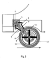
Figure 6 shows a detailed view of an example of the application in a conventional motor vehicle with a combustion engine. - As can be seen in the attached drawings, the electromechanical drive mechanism for motor vehicles with combustion engines, object of the present invention patent, is formed by an electric generator/engine (1) acting as an engine when it is fed electric power, and as a generator when the vehicle decelerates; it is anchored in a support (17) with bearings on which it rotates, and the function is that when power is applied the armature rotates with its shaft (2) in one direction, whereas due to the effect of the opposite torque moment, the stator rotates in the opposite direction. This latter movement is what actuates the mechanical drive system with force in one direction or the other until the pinion comes against the inner rack or ring (11), since the system is coupled to the stator. The drive shaft (2) meshes with the input shaft (3), which is integrally joined to the counter shaft (4) by means of the toothed belt (5); the lower part (6) of the mechanical drive system slides inside the intermediate part (7) of the mechanical drive system, in correspondence with the vertical oscillations of the rim (12) of the vehicle due to the uneven terrain, maintaining the drive at all times, said intermediate part can in turn be regulated in length inside the upper part (13) of the mechanical drive system by means of four clamping screws (14) as needed in order to be able to adapt to any distance from the drive shaft (2) to the inner rack or ring (11) incorporated on the rim (12) of the vehicle. Tension devices (8) are responsible for adjusting the tension that the toothed belt (5) may have on the loose side at that time, and serving as a damper for the lower part (6) of the mechanical drive system containing the counter shaft (4) having a pinion (10) at its end acting on the inner rack or ring (11) incorporated on the rim (12) of the wheel of the vehicle. The regulating idler roller (9) coupled at a suitable distance from the pinion (10) slides in the rear circular groove of the inner rack or ring (11) incorporated on the rim (12) of the vehicle; its function is to prevent the pinion (10) from rubbing against the inner rack or ring (11) when the rim oscillates due to the uneven terrain, when both are not driving, or is in the neutral position (N); when the opposite torque moment makes the mechanical drive system rotate to one side (D) or the other (R), the pinion (10) drives the inner rack or ring (11).
- Another different form of action in order to be able to regulate the distance between the pinion and the inner rack or ring (11) is to actuate the roller (9) in the longitudinal direction by means of a small motor (16) through a screw, which incorporates the fastening of the roller (9) in the rear area of the lower part (6) of the mechanical drive system.
- Having sufficiently described the nature of the present invention as well as a way of carrying it out to practice, all that is left to be added is that said invention can undergo certain variations in terms of shape and materials provided that said alterations do not substantially vary the features claimed below.
Claims (5)
- An electromechanical drive mechanism for motor vehicles with combustion engines, characterized by having two electric generators/engines (1) rotating on a support (17) with the opposite torque moment joined to the body in the boot of the vehicle, the drive shaft (2) of which meshes with the input shaft (3) which is integrally joined to the upper part (13) of the mechanical drive system of the mechanism and in turn to the counter shaft (4) by means of the toothed belt (5); the lower part (6) of the mechanical drive system slides inside the intermediate part (7) of the mechanical drive system and said intermediate part is in turn manually adjusted inside the upper part (13) of the mechanical drive system to adapt the distance from the drive shaft (2) to the inner rack or ring (11) of the rim (12) of the vehicle; tension devices (8) adjust the tension of the loose side of the toothed belt (5) and dampen the lower part (6) of the mechanical drive system containing the counter shaft (4) incorporating a pinion (10) at its end acting on the inner rack or ring (11) incorporated in the rim (12) of the vehicle; the idler roller (9) coupled together with the pinion (10) slides in the rear circular groove of the inner rack or ring (11).
- An electromechanical drive mechanism for motor vehicles with combustion engines according to claim 1, characterized in that it consists of three parts: the fixed upper part (13) of the mechanical drive system; the adjustable intermediate part (7) of the mechanical drive system; the sliding lower part (6) of the mechanical drive system regulated by the force of tension devices (8).
- An electromechanical drive mechanism for motor vehicles with combustion engines according to claim 1, characterized in that the lower part (6) of the mechanical drive system of the mechanism incorporates a pinion (10) acting on the inner rack or ring (11) of the rim (12) of the vehicle and an idler roller (9), which can be fixed or mobile, actuated by a small motor (16).
- An electromechanical drive mechanism for motor vehicles with combustion engines according to claim 1, characterized in that the stator of the engine (1) uses the opposite torque moment to move the drive mechanism to both sides.
- An electromechanical drive mechanism for motor vehicles with combustion engines according to claim 1, characterized in that the rim (12) of the vehicle incorporates an inner rack or ring (11) that is active on both sides on which the idler roller (9) slides and the pinion (10) acts.
Applications Claiming Priority (2)
| Application Number | Priority Date | Filing Date | Title |
|---|---|---|---|
| ES200501344 | 2005-06-03 | ||
| PCT/ES2006/070069 WO2006128942A1 (en) | 2005-06-03 | 2006-05-23 | Electromechanical drive mechanism for motor vehicles with combustion engines |
Publications (1)
| Publication Number | Publication Date |
|---|---|
| EP1892138A1 true EP1892138A1 (en) | 2008-02-27 |
Family
ID=37481253
Family Applications (1)
| Application Number | Title | Priority Date | Filing Date |
|---|---|---|---|
| EP06755383A Withdrawn EP1892138A1 (en) | 2005-06-03 | 2006-05-23 | Electromechanical drive mechanism for motor vehicles with combustion engines |
Country Status (2)
| Country | Link |
|---|---|
| EP (1) | EP1892138A1 (en) |
| WO (1) | WO2006128942A1 (en) |
Cited By (1)
| Publication number | Priority date | Publication date | Assignee | Title |
|---|---|---|---|---|
| IT201700070192A1 (en) * | 2017-06-23 | 2018-12-23 | Texa Dynamics S R L | "Traction and suspension system" |
Family Cites Families (5)
| Publication number | Priority date | Publication date | Assignee | Title |
|---|---|---|---|---|
| FR523321A (en) * | 1919-10-09 | 1921-08-17 | Louis Eugene Deschamps | Transmission for motor cars |
| DE3640947A1 (en) * | 1986-11-29 | 1988-06-09 | Deere & Co | Transmission for a steerable wheel |
| JPH0485136A (en) * | 1990-07-25 | 1992-03-18 | Kubota Corp | Walking type working machine |
| US5680907A (en) * | 1995-02-17 | 1997-10-28 | Weihe; Clyde R. | Auxiliary solar-power automobile drive system |
| US6880654B2 (en) * | 2003-03-28 | 2005-04-19 | Paul J. Plishner | Vehicle with a distributed motor |
-
2006
- 2006-05-23 WO PCT/ES2006/070069 patent/WO2006128942A1/en active Application Filing
- 2006-05-23 EP EP06755383A patent/EP1892138A1/en not_active Withdrawn
Non-Patent Citations (1)
| Title |
|---|
| See references of WO2006128942A1 * |
Cited By (4)
| Publication number | Priority date | Publication date | Assignee | Title |
|---|---|---|---|---|
| IT201700070192A1 (en) * | 2017-06-23 | 2018-12-23 | Texa Dynamics S R L | "Traction and suspension system" |
| WO2018234923A1 (en) * | 2017-06-23 | 2018-12-27 | Texa Dynamics S.R.L. | Traction and suspension system |
| CN110891803A (en) * | 2017-06-23 | 2020-03-17 | 德萨动力有限公司 | Traction and suspension system |
| US11273678B2 (en) | 2017-06-23 | 2022-03-15 | Texa Dynamics S.R.L. | Traction and suspension system |
Also Published As
| Publication number | Publication date |
|---|---|
| WO2006128942A1 (en) | 2006-12-07 |
Similar Documents
| Publication | Publication Date | Title |
|---|---|---|
| JP5308489B2 (en) | Drive system and automobile having the drive system | |
| CN100358744C (en) | Hybrid drive device and automobile with device mounted thereon | |
| EP2156975B1 (en) | Hybrid driving unit and vehicle carrying the same | |
| JP5137596B2 (en) | Hybrid electric vehicle powertrain | |
| JP4505137B2 (en) | Especially transmission systems for automobiles | |
| JP5784050B2 (en) | Gear device and drive device | |
| JP5630718B2 (en) | Power transmission device using planetary gears | |
| JP5318387B2 (en) | Axle drive unit for drivetrain | |
| JP2019502059A (en) | CVT differential | |
| US8862298B2 (en) | Drive control device of hybrid vehicle | |
| KR20070021445A (en) | Hybrid vehicles | |
| JP6135418B2 (en) | Power transmission device for hybrid vehicle | |
| JP2009143348A (en) | Drive device for hybrid vehicle | |
| JP4247748B2 (en) | Hybrid drive device | |
| US20090294190A1 (en) | Electrical Gearbox With Continuous Variation | |
| KR20170121518A (en) | Reducer for active stabilizer | |
| WO2007063429A3 (en) | Vehicular driving power distribution device | |
| US6955624B2 (en) | Motor vehicle drivetrain having at least two CNT's and flywheels | |
| EP1892138A1 (en) | Electromechanical drive mechanism for motor vehicles with combustion engines | |
| EP1063118B1 (en) | Power train system for a vehicle | |
| US20200254870A1 (en) | Two-speed automatic mechanical transmission electric axle assembly | |
| KR100534198B1 (en) | Power delivery apparatus | |
| KR100922865B1 (en) | A stepless transmission | |
| CN214888689U (en) | Differential device of electronic speed governing | |
| US11732780B2 (en) | Electric vehicle transmission |
Legal Events
| Date | Code | Title | Description |
|---|---|---|---|
| PUAI | Public reference made under article 153(3) epc to a published international application that has entered the european phase |
Free format text: ORIGINAL CODE: 0009012 |
|
| 17P | Request for examination filed |
Effective date: 20071219 |
|
| AK | Designated contracting states |
Kind code of ref document: A1 Designated state(s): AT BE BG CH CY CZ DE DK EE ES FI FR GB GR HU IE IS IT LI LT LU LV MC NL PL PT RO SE SI SK TR |
|
| DAX | Request for extension of the european patent (deleted) | ||
| STAA | Information on the status of an ep patent application or granted ep patent |
Free format text: STATUS: THE APPLICATION IS DEEMED TO BE WITHDRAWN |
|
| 18D | Application deemed to be withdrawn |
Effective date: 20131203 |