EP1892115A1 - Method of forming a phase change ink image on a self-laminating recording medium - Google Patents
Method of forming a phase change ink image on a self-laminating recording medium Download PDFInfo
- Publication number
- EP1892115A1 EP1892115A1 EP07113964A EP07113964A EP1892115A1 EP 1892115 A1 EP1892115 A1 EP 1892115A1 EP 07113964 A EP07113964 A EP 07113964A EP 07113964 A EP07113964 A EP 07113964A EP 1892115 A1 EP1892115 A1 EP 1892115A1
- Authority
- EP
- European Patent Office
- Prior art keywords
- ink
- fusible layer
- layer
- recording medium
- fusible
- Prior art date
- Legal status (The legal status is an assumption and is not a legal conclusion. Google has not performed a legal analysis and makes no representation as to the accuracy of the status listed.)
- Granted
Links
- 238000000034 method Methods 0.000 title claims abstract description 43
- 230000008859 change Effects 0.000 title description 4
- 238000010030 laminating Methods 0.000 title 1
- 239000000203 mixture Substances 0.000 claims abstract description 34
- 230000001681 protective effect Effects 0.000 claims abstract description 11
- 239000007788 liquid Substances 0.000 claims abstract description 7
- 239000007787 solid Substances 0.000 claims abstract description 7
- 239000000463 material Substances 0.000 claims description 14
- 238000012546 transfer Methods 0.000 claims description 8
- 230000009477 glass transition Effects 0.000 claims description 7
- 239000002178 crystalline material Substances 0.000 claims description 4
- 239000012815 thermoplastic material Substances 0.000 claims description 4
- 238000007650 screen-printing Methods 0.000 claims description 3
- 239000000976 ink Substances 0.000 description 116
- 239000010410 layer Substances 0.000 description 98
- 239000002609 medium Substances 0.000 description 75
- 229920005989 resin Polymers 0.000 description 19
- 239000011347 resin Substances 0.000 description 19
- -1 polyethylene terephthalate Polymers 0.000 description 14
- 239000002245 particle Substances 0.000 description 11
- 238000007669 thermal treatment Methods 0.000 description 11
- 239000011248 coating agent Substances 0.000 description 9
- 238000000576 coating method Methods 0.000 description 9
- 239000006185 dispersion Substances 0.000 description 9
- 239000012943 hotmelt Substances 0.000 description 9
- 239000000758 substrate Substances 0.000 description 9
- 239000011230 binding agent Substances 0.000 description 8
- 229920000642 polymer Polymers 0.000 description 8
- 239000012530 fluid Substances 0.000 description 7
- VYPSYNLAJGMNEJ-UHFFFAOYSA-N Silicium dioxide Chemical compound O=[Si]=O VYPSYNLAJGMNEJ-UHFFFAOYSA-N 0.000 description 6
- 238000010438 heat treatment Methods 0.000 description 5
- 239000011148 porous material Substances 0.000 description 5
- 229920001225 polyester resin Polymers 0.000 description 4
- 239000004645 polyester resin Substances 0.000 description 4
- 229920001169 thermoplastic Polymers 0.000 description 4
- XLYOFNOQVPJJNP-UHFFFAOYSA-N water Substances O XLYOFNOQVPJJNP-UHFFFAOYSA-N 0.000 description 4
- 150000001875 compounds Chemical class 0.000 description 3
- 230000007423 decrease Effects 0.000 description 3
- 239000003349 gelling agent Substances 0.000 description 3
- 230000003993 interaction Effects 0.000 description 3
- 238000002844 melting Methods 0.000 description 3
- 230000008018 melting Effects 0.000 description 3
- 239000012071 phase Substances 0.000 description 3
- 229920000728 polyester Polymers 0.000 description 3
- 229920002451 polyvinyl alcohol Polymers 0.000 description 3
- 238000007639 printing Methods 0.000 description 3
- 230000008569 process Effects 0.000 description 3
- 239000000377 silicon dioxide Substances 0.000 description 3
- 239000000126 substance Substances 0.000 description 3
- 239000004416 thermosoftening plastic Substances 0.000 description 3
- VTYYLEPIZMXCLO-UHFFFAOYSA-L Calcium carbonate Chemical compound [Ca+2].[O-]C([O-])=O VTYYLEPIZMXCLO-UHFFFAOYSA-L 0.000 description 2
- 108010010803 Gelatin Proteins 0.000 description 2
- 239000004372 Polyvinyl alcohol Substances 0.000 description 2
- 241000519995 Stachys sylvatica Species 0.000 description 2
- XLOMVQKBTHCTTD-UHFFFAOYSA-N Zinc monoxide Chemical compound [Zn]=O XLOMVQKBTHCTTD-UHFFFAOYSA-N 0.000 description 2
- TZCXTZWJZNENPQ-UHFFFAOYSA-L barium sulfate Chemical compound [Ba+2].[O-]S([O-])(=O)=O TZCXTZWJZNENPQ-UHFFFAOYSA-L 0.000 description 2
- 230000008901 benefit Effects 0.000 description 2
- 230000006866 deterioration Effects 0.000 description 2
- 238000001035 drying Methods 0.000 description 2
- 230000000694 effects Effects 0.000 description 2
- 239000004744 fabric Substances 0.000 description 2
- 238000009472 formulation Methods 0.000 description 2
- 229920000159 gelatin Polymers 0.000 description 2
- 239000008273 gelatin Substances 0.000 description 2
- 235000019322 gelatine Nutrition 0.000 description 2
- 235000011852 gelatine desserts Nutrition 0.000 description 2
- 238000007641 inkjet printing Methods 0.000 description 2
- 239000010954 inorganic particle Substances 0.000 description 2
- 239000011159 matrix material Substances 0.000 description 2
- 239000011146 organic particle Substances 0.000 description 2
- 239000011236 particulate material Substances 0.000 description 2
- 229920002401 polyacrylamide Polymers 0.000 description 2
- 229920006149 polyester-amide block copolymer Polymers 0.000 description 2
- 229920002959 polymer blend Polymers 0.000 description 2
- 239000011241 protective layer Substances 0.000 description 2
- 230000005855 radiation Effects 0.000 description 2
- 238000006748 scratching Methods 0.000 description 2
- 230000002393 scratching effect Effects 0.000 description 2
- GJCOSYZMQJWQCA-UHFFFAOYSA-N 9H-xanthene Chemical compound C1=CC=C2CC3=CC=CC=C3OC2=C1 GJCOSYZMQJWQCA-UHFFFAOYSA-N 0.000 description 1
- 229920000178 Acrylic resin Polymers 0.000 description 1
- 239000004925 Acrylic resin Substances 0.000 description 1
- 229920001817 Agar Polymers 0.000 description 1
- 102000009027 Albumins Human genes 0.000 description 1
- 108010088751 Albumins Proteins 0.000 description 1
- 241000416162 Astragalus gummifer Species 0.000 description 1
- 229920002101 Chitin Polymers 0.000 description 1
- 229920001661 Chitosan Polymers 0.000 description 1
- 102000008186 Collagen Human genes 0.000 description 1
- 108010035532 Collagen Proteins 0.000 description 1
- 244000303965 Cyamopsis psoralioides Species 0.000 description 1
- 229920002307 Dextran Polymers 0.000 description 1
- IMROMDMJAWUWLK-UHFFFAOYSA-N Ethenol Chemical compound OC=C IMROMDMJAWUWLK-UHFFFAOYSA-N 0.000 description 1
- YCKRFDGAMUMZLT-UHFFFAOYSA-N Fluorine atom Chemical compound [F] YCKRFDGAMUMZLT-UHFFFAOYSA-N 0.000 description 1
- 241000206672 Gelidium Species 0.000 description 1
- 244000151018 Maranta arundinacea Species 0.000 description 1
- 235000010804 Maranta arundinacea Nutrition 0.000 description 1
- 229920001890 Novodur Polymers 0.000 description 1
- 239000004698 Polyethylene Substances 0.000 description 1
- 239000004793 Polystyrene Substances 0.000 description 1
- 229920002125 Sokalan® Polymers 0.000 description 1
- 235000012419 Thalia geniculata Nutrition 0.000 description 1
- 229920001615 Tragacanth Polymers 0.000 description 1
- XTXRWKRVRITETP-UHFFFAOYSA-N Vinyl acetate Chemical compound CC(=O)OC=C XTXRWKRVRITETP-UHFFFAOYSA-N 0.000 description 1
- 229920002494 Zein Polymers 0.000 description 1
- 239000000654 additive Substances 0.000 description 1
- 235000010419 agar Nutrition 0.000 description 1
- PNEYBMLMFCGWSK-UHFFFAOYSA-N aluminium oxide Inorganic materials [O-2].[O-2].[O-2].[Al+3].[Al+3] PNEYBMLMFCGWSK-UHFFFAOYSA-N 0.000 description 1
- 238000005267 amalgamation Methods 0.000 description 1
- 239000012736 aqueous medium Substances 0.000 description 1
- 239000003125 aqueous solvent Substances 0.000 description 1
- 238000000149 argon plasma sintering Methods 0.000 description 1
- 239000011324 bead Substances 0.000 description 1
- 230000000903 blocking effect Effects 0.000 description 1
- 229910000019 calcium carbonate Inorganic materials 0.000 description 1
- 239000000679 carrageenan Substances 0.000 description 1
- 235000010418 carrageenan Nutrition 0.000 description 1
- 229920001525 carrageenan Polymers 0.000 description 1
- 229940113118 carrageenan Drugs 0.000 description 1
- 239000005018 casein Substances 0.000 description 1
- BECPQYXYKAMYBN-UHFFFAOYSA-N casein, tech. Chemical compound NCCCCC(C(O)=O)N=C(O)C(CC(O)=O)N=C(O)C(CCC(O)=N)N=C(O)C(CC(C)C)N=C(O)C(CCC(O)=O)N=C(O)C(CC(O)=O)N=C(O)C(CCC(O)=O)N=C(O)C(C(C)O)N=C(O)C(CCC(O)=N)N=C(O)C(CCC(O)=N)N=C(O)C(CCC(O)=N)N=C(O)C(CCC(O)=O)N=C(O)C(CCC(O)=O)N=C(O)C(COP(O)(O)=O)N=C(O)C(CCC(O)=N)N=C(O)C(N)CC1=CC=CC=C1 BECPQYXYKAMYBN-UHFFFAOYSA-N 0.000 description 1
- 235000021240 caseins Nutrition 0.000 description 1
- 239000001913 cellulose Substances 0.000 description 1
- 229920002678 cellulose Polymers 0.000 description 1
- 229920003086 cellulose ether Polymers 0.000 description 1
- 239000004927 clay Substances 0.000 description 1
- 229910052570 clay Inorganic materials 0.000 description 1
- 229920001436 collagen Polymers 0.000 description 1
- 229920001577 copolymer Polymers 0.000 description 1
- 238000002425 crystallisation Methods 0.000 description 1
- 230000001419 dependent effect Effects 0.000 description 1
- 238000013461 design Methods 0.000 description 1
- 238000010586 diagram Methods 0.000 description 1
- 239000000428 dust Substances 0.000 description 1
- 229920001971 elastomer Polymers 0.000 description 1
- 238000010304 firing Methods 0.000 description 1
- 229910052731 fluorine Inorganic materials 0.000 description 1
- 239000011737 fluorine Substances 0.000 description 1
- 239000011888 foil Substances 0.000 description 1
- 229920001477 hydrophilic polymer Polymers 0.000 description 1
- 230000002209 hydrophobic effect Effects 0.000 description 1
- 229920001600 hydrophobic polymer Polymers 0.000 description 1
- 238000005259 measurement Methods 0.000 description 1
- 238000010297 mechanical methods and process Methods 0.000 description 1
- 230000007246 mechanism Effects 0.000 description 1
- 229910052751 metal Inorganic materials 0.000 description 1
- 239000002184 metal Substances 0.000 description 1
- 229920000609 methyl cellulose Polymers 0.000 description 1
- 239000001923 methylcellulose Substances 0.000 description 1
- 230000005012 migration Effects 0.000 description 1
- 238000013508 migration Methods 0.000 description 1
- 239000002105 nanoparticle Substances 0.000 description 1
- 239000012457 nonaqueous media Substances 0.000 description 1
- 239000001814 pectin Substances 0.000 description 1
- 229920001277 pectin Polymers 0.000 description 1
- 235000010987 pectin Nutrition 0.000 description 1
- 229920003023 plastic Polymers 0.000 description 1
- 239000004033 plastic Substances 0.000 description 1
- 229920000233 poly(alkylene oxides) Polymers 0.000 description 1
- 229920005668 polycarbonate resin Polymers 0.000 description 1
- 239000004431 polycarbonate resin Substances 0.000 description 1
- 238000006068 polycondensation reaction Methods 0.000 description 1
- 229920000573 polyethylene Polymers 0.000 description 1
- 229920000139 polyethylene terephthalate Polymers 0.000 description 1
- 239000005020 polyethylene terephthalate Substances 0.000 description 1
- 229920000098 polyolefin Polymers 0.000 description 1
- 229920002223 polystyrene Polymers 0.000 description 1
- 229920001343 polytetrafluoroethylene Polymers 0.000 description 1
- 229920002635 polyurethane Polymers 0.000 description 1
- 239000004814 polyurethane Substances 0.000 description 1
- 229920000915 polyvinyl chloride Polymers 0.000 description 1
- 229920000036 polyvinylpyrrolidone Polymers 0.000 description 1
- 239000001267 polyvinylpyrrolidone Substances 0.000 description 1
- 235000013855 polyvinylpyrrolidone Nutrition 0.000 description 1
- 238000011160 research Methods 0.000 description 1
- 229920002379 silicone rubber Polymers 0.000 description 1
- 239000007790 solid phase Substances 0.000 description 1
- 239000002904 solvent Substances 0.000 description 1
- 239000002344 surface layer Substances 0.000 description 1
- 238000012360 testing method Methods 0.000 description 1
- 239000000196 tragacanth Substances 0.000 description 1
- 235000010487 tragacanth Nutrition 0.000 description 1
- 229940116362 tragacanth Drugs 0.000 description 1
- 125000000391 vinyl group Chemical group [H]C([*])=C([H])[H] 0.000 description 1
- 229920002554 vinyl polymer Polymers 0.000 description 1
- 239000000080 wetting agent Substances 0.000 description 1
- 229920001285 xanthan gum Polymers 0.000 description 1
- 239000005019 zein Substances 0.000 description 1
- 229940093612 zein Drugs 0.000 description 1
- 239000011787 zinc oxide Substances 0.000 description 1
- UHVMMEOXYDMDKI-JKYCWFKZSA-L zinc;1-(5-cyanopyridin-2-yl)-3-[(1s,2s)-2-(6-fluoro-2-hydroxy-3-propanoylphenyl)cyclopropyl]urea;diacetate Chemical compound [Zn+2].CC([O-])=O.CC([O-])=O.CCC(=O)C1=CC=C(F)C([C@H]2[C@H](C2)NC(=O)NC=2N=CC(=CC=2)C#N)=C1O UHVMMEOXYDMDKI-JKYCWFKZSA-L 0.000 description 1
Images


Classifications
-
- B—PERFORMING OPERATIONS; TRANSPORTING
- B41—PRINTING; LINING MACHINES; TYPEWRITERS; STAMPS
- B41M—PRINTING, DUPLICATING, MARKING, OR COPYING PROCESSES; COLOUR PRINTING
- B41M7/00—After-treatment of prints, e.g. heating, irradiating, setting of the ink, protection of the printed stock
- B41M7/0027—After-treatment of prints, e.g. heating, irradiating, setting of the ink, protection of the printed stock using protective coatings or layers by lamination or by fusion of the coatings or layers
-
- B—PERFORMING OPERATIONS; TRANSPORTING
- B41—PRINTING; LINING MACHINES; TYPEWRITERS; STAMPS
- B41M—PRINTING, DUPLICATING, MARKING, OR COPYING PROCESSES; COLOUR PRINTING
- B41M7/00—After-treatment of prints, e.g. heating, irradiating, setting of the ink, protection of the printed stock
- B41M7/009—After-treatment of prints, e.g. heating, irradiating, setting of the ink, protection of the printed stock using thermal means, e.g. infrared radiation, heat
Definitions
- the ink composition In order to print the ink composition by way of an ink jet head, the ink composition needs to be in the fluid state. This requires the use of an ink jet head that can operate at temperatures above the melting temperature of the ink, typically at temperatures between 90 and 140°C.
- print heads can be used that comprise heated pressure chambers filled with the fluid ink and connected to nozzles, wherein the pressure required to fire a droplet is generated by firing a transducer, such as for example a piezo-electric transducer.
- Such a layer can contain organic or inorganic particles and typically has a thickness of about 1 ⁇ m to about 50 ⁇ m.
- organic particles that may be used include acrylic resins, styrenic resins, cellulose derivatives, polyvinyl resins, ethylene-allyl copolymers and polycondensation polymers.
- inorganic particles that can be used in the ink receiving layer include silica, alumina, titianium dioxide, clay, calcium carbonate, barium sulfate or zinc oxide.
- the fusible layer is provided on the support via a screen printing technique.
- a screen printing technique which in itself is commonly known, in a very simple and convenient way a porosity can be provided that is adequate to allow fluid hot melt ink to pass into the recording medium, while still being “dense” enough to allow adequate fusing under moderate loads, such as for example a moderate temperature and/or pressure rise.
- Other techniques such as rod coating of resins, or resin dispersions in aqueous or non-aqueous solvents, optionally in addition with a mechanical method to force pores or interstices in the fusible layer, can provide for the same result but are less practical in use.
- the control arrangement can be any piece of hardware that is designed to control the thermal treatment of the recording medium (for example in the form of an ASIC). However, the control arrangement does not essentially need to be one single piece of hardware, it may be distributed over the system. Moreover, this arrangement can in a smaller or larger part be provided in the form of software running on one or more processors (generic and/or programmable), which software is used to control the corresponding hardware. All kinds of control arrangements can be designed to be suitable, as long as they are capable of adequately controlling the thermal treatment of the recording medium in line with the present invention.
- a clean screen that is commonly used in a screen printer is placed on top of a suitable substrate, in this case Kodak Instant Dry Glossy photopaper, 190 g. It is ensured that there is good contact between the screen and the substrate by supporting the substrate and putting adequate pressure on the framework of the screen.
- the screen in this case is made out of mono-filaments of an inert fabric, which filaments are 40 micron wide leaving openings of 20 x 20 micrometers.
- Each of these ink compositions contains a crystalline material (K), an amorphous material (A) and a gelling agent (G).
- the ink compositions are provided with a dye (KI), Macrolex Rot (Bayer) in the case of the ink compositions I and III, Orasol Blau (Ciba-Geigy) in the case of composition II.
- the three ink compositions are provided with wetting agent (V) BYK 307 (Byk Chemie).
- the chemical formulae of the crystalline base material (K), the amorphous binder (A) and the gelling agent (G) are given in tables 2, 3a and 1 respectively of EP 1 067 157 . Table 1.
- a first relevant feature of the image quality is the gloss level (which can be measured for example using a Hunter 75° glossmeter according to TAPPI procedure T 480 OM-92).
- Another feature is the appearance of white spots, possibly a crystallisation effect of the crystalline material in the ink vehicle. It appears that during the first few days a slight deterioration of the gloss level occurs (typically from 70 to 60%). However, this decrease in gloss can hardly be noticed with the naked human eye. After that, the gloss level remains substantially constant, up to even 800 hours of thermal load. No white spots can be noticed wit the naked human eye.
Landscapes
- Ink Jet (AREA)
- Ink Jet Recording Methods And Recording Media Thereof (AREA)
Abstract
Description
- The invention pertains to a method of creating an image on a recording medium with an ink composition that is solid at room temperature and liquid at elevated temperature. The invention also pertains to a system for creating an image on a recording medium with said ink composition.
- A method of creating an image on a recording medium with an ink composition that is solid at room temperature and liquid at elevated temperature (also called "hot melt" or "phase change ink") is known from
US 6,497,940 . This patent describes a recording medium for the ink composition which has improved clarity, improved resistance to surface scratching and improved ink adhesion. The recording medium comprises a polyethylene terephthalate support coated with a lower receptor layer comprising 82-97 wt.% of silica and 3-18 wt.% of PVA, polyvinylpyrrolidone, polyacrylamide, methylcellulose or gelatin. An optional upper layer comprises 32-70 wt.% of a matrix polymer, 15-52 wt.% of inorganic particulate material and 5-53 wt.% of soft polymer mixture. The term 'soft polymer mixture' describes a polymer or mixture of polymers that soften during the image transfer step of the printing. The softening allows the ink composition and the upper layer to become chemically or physically mated for mechanical durability reasons. The soft polymer matrix must be sufficiently soft to allow the ink composition and the coating to become intimately interrelated and yet rigid enough to avoid scratching and sticking with adjoining films. - Although suitable to obtain adequate mechanical durability, a disadvantage of this known method is that the print quality deteriorates when the printed medium is subjected to thermal load, for example by storing the printed medium at 35°C for several weeks or months. It is for example noticed that the gloss level decreases substantially, and that local artefacts arise in the printed images.
- The object of the present invention is to provide an improved method of obtaining images of a hot melt ink that overcomes or at least mitigates the disadvantages of the known method. To this end an ink jet printing method has been devised, using a recording medium comprising a support having thereon a porous fusible layer, comprising the steps of generating droplets of the ink composition with an ink jet print head, transferring the droplets of the ink composition to the surface of the fusible layer, thermally treating the recording medium such that the ink transferred to fusible layer passes into the medium away from the surface of the fusible layer whilst the fusible layer remains substantially unfused, and when the ink has passed into the medium, treating the recording medium to fuse the fusible layer to become a protective overcoat.
- With this method, in contrast with the prior art method, the ink, due to the thermal treatment, passes into the medium such that an upper layer arises that is substantially free of ink, i.e. substantially free of at least the meltable vehicle components of the ink (which typically constitute 90-99% of the hot melt ink). Then, this upper layer is fused (optionally together with other parts of the medium), which can be done by any known physical or chemical method that allows the porous layer to become a fused layer, to become a protective overcoat. This way a continuous film (i.e. a film wherein the pores or interstices have disappeared for the major part) is created that substantially shuts off interaction between the environment and the ink trapped in the medium. It appears that, next to a very good mechanical durability, a very durable high gloss can be achieved with the method according to the present invention, even under circumstances of relatively high thermal load.
Inventors have found that a porous fusible layer, i.e. a layer having pores or interstices permitting the passage of fluid ink, in itself is not sufficient to arrive at the result that is obtainable with the present invention. It is essential that the recording medium is thermally treated such that the ink passes into the medium away from the surface of the fusible layer. Otherwise, ink can remain on the surface and thus an ink free upper layer cannot be readily provided. However, the thermal treatment should be such that the fusible layer remains substantially unfused while the ink passes into the medium. This is to prevent the too early amalgamation of the ink and the fusible layer as is known from the prior art. The thermal treatment in itself is not restricted to any type of treatment but can be for example radiation treatment, contact treatment, conductive treatment etc. This treatment can take place before the ink is transferred to the surface of the recording medium (pre-heating of the medium), at the same time, afterwards, or even a combination of these methods can be used, as long as it leads to a temperature rise of (parts of) the medium that allow passing of the hot melt ink into the medium whilst preventing substantial fusing of the fusible layer. - In the method according to the present invention, the treatment to fuse the porous layer should not be performed until the ink has passed into the medium to create an ink free upper layer. It is noted however that the treatment to fuse the porous layer and the thermal treatment to allow the ink to pass into the medium could for example be accomplished by a one-step thermal treatment, for example by passing the printed recording medium through one single pair of heated rollers. By applying such heated rollers namely, the viscosity of the ink droplets that reside on the surface of the porous layer can be forced to decrease to a value of typically about 10 mPa.s when heated above the melting point of the ink (for example, heating to 120°C for an ink with a melting point of 90°C). Although such a high temperature might also be sufficient to fuse a fusible layer consisting out of a polyester polymer with a glass-transition temperature of for example 65°C, the time scale for the migration of the fluid ink into the medium is typically much (10 to 1000 times) shorter than the time scale for the fusing of the fusible (polymer) layer. Thus, what appears to be one single thermal treatment at first glance, can, under certain circumstances and with the right choice of materials in effect be regarded as a first treatment enabling ink to pass into the medium to provide an ink free upper layer, followed by a treatment to fuse the fusible layer, i.e. at least the ink free upper part of that layer, to form a closed, protective overcoat.
- Ink compositions that are solid at room temperature and liquid at an elevated temperature are commonly known. Examples of such an ink compositions are given in
EP 1 067 157497067 - In order to print the ink composition by way of an ink jet head, the ink composition needs to be in the fluid state. This requires the use of an ink jet head that can operate at temperatures above the melting temperature of the ink, typically at temperatures between 90 and 140°C. To this end print heads can be used that comprise heated pressure chambers filled with the fluid ink and connected to nozzles, wherein the pressure required to fire a droplet is generated by firing a transducer, such as for example a piezo-electric transducer.
- The recording medium as used in the method according to the present invention comprises a support for the porous fusible layer. This support can be opaque, translucent or transparent. There may be used, for example, plain papers, resin coated paper, various plastics including a polyester resin such as poly(ethylene-terephtalate), poly(ethylene-naphtalate), a polycarbonate resin, a fluorine resin such as poly(tetrafluoro ethylene), metal foil, vinyl, fabric, laminated or coextruded supports. Inkjet papers that can be used as a support in the meaning of the present invention are also described in the proceedings of the TAPPI Coating Conference of 2002, that is, in the paper by Hyun-Kook Lee, Margaret Joyce, Paul Flemming and John Cameron of the Western Michigan University (see for example Table 1 of this paper).
- The fusible layer may comprise e.g. fusible polymeric particles. The particles may have any size provided that when constituted as a layer, they provide for pores or interstices that allow the fluid ink to pass into the medium and create an ink free upper layer, and that they upon a fusing treatment will coalesce to form a continuous overcoat film. Typical particle size are in the range of 1-10 micrometers.
- It is noted that
US 6,497,480 describes an ink jet recording element comprising a support having, in sequence, a porous ink-retaining layer and a fusible porous ink-transporting layer comprising fusible polymeric particles and a film-forming hydrophobic binder.US 6,811 ,253 describes an ink jet printing method, comprising printing onto a receiving medium having an ink receiving layer and an upper protective layer and heating the printed image to form a stable image-protecting coating. The upper protective layer comprises particulate polymeric beads having a film-forming temperature of 100-120 °C with a hydrophilic binder. This invention conveniently protects ink jet images.
The technical disclosure of these patents however is restricted to the use of water or solvent based inks. These inks are completely different from hot melt inks, not only in their intrinsic properties, but also in their behaviour when printed on media. In particular, these inks do not suffer from the problem of gloss deterioration when printed on dedicated ink jet gloss media. Next to that, these inks are fluid at room temperature and thus readily migrate through the fusible ink transporting layer into the ink receiving layer. Indeed, both references remain silent about a thermal treatment enabling the ink to pass into the recording medium. Thus, it is clear that the method according to the present invention is not known from or obviated by the disclosure of these references. - In an embodiment of the present invention the recording medium that is used has a support comprising a base layer and thereon an ink receiving layer. The base layer may be any suitable layer for providing adequate mechanical strength or other property if needed (depending on the application). The ink receiving layer is designed to absorb the ink that passes into the medium. Such an absorptive layer can be constituted in many forms, as long as the interaction with the ink is such that this ink can be absorbed, either partly or completely, in this layer. In a further embodiment the ink receiving layer is a micro-porous layer. Such a layer comprises pores or interstices with a cross-section around the (sub-)micrometer range. Such a layer can contain organic or inorganic particles and typically has a thickness of about 1 µm to about 50 µm. Examples of organic particles that may be used include acrylic resins, styrenic resins, cellulose derivatives, polyvinyl resins, ethylene-allyl copolymers and polycondensation polymers. Examples of inorganic particles that can be used in the ink receiving layer include silica, alumina, titianium dioxide, clay, calcium carbonate, barium sulfate or zinc oxide. The micro-porous ink receiving layer may comprise from about 20% to about 100% of particles and from about 0% to about 80% of polymeric binder, preferably from about 80% to about 95% of polymeric particles and from about 20% to 5% of polymeric binder. The polymeric binder may be a hydrophilic or hydrophobic polymer (depending i.a. on the type of ink for which the receiving medium is designed), such as poly(vinyl alcohol), poly(vinylpyrrolidone), gelatin, cellulose ethers, poly(oxazolines), poly(vinylacetamides), partially hydrolyzed poly(vinyl acetate/vinyl alcohol), poly(acrylic acid), poly(acrylamide), poly(alkylene oxide), sufonated or phosphared polyesters and polystyrenes, casein, zein, albumin, chitin, chitosan, dextran, pectin, collagen derivatives, collodian, agar-agar, arrowroot, guar, carrageenan, tragacanth, xanthan, rhamsan and the like.
- In an embodiment the porous fusible layer comprises a thermoplastic material. This has the advantage that a thermal treatment can be used to fuse the layer to from the continuous protective overcoat. The material constituting the fusible layer can in principle be any thermoplastic material composed from a thermoplastic compound only, or from a combination of a thermoplastic compound with for example a film forming polymer or other additives (in any ratio), depending on the specific application of the recorded medium. For example, if the recorded medium will be subjected to temperatures above 80°C, it is recommended that a thermoplastic material is being used having a glass transition temperature above 80°C, in particular above 90°C.
- Examples of suitable thermoplastic compounds include polyesters, polyesteramides, polyethylenes and polyurethanes.
- In another embodiment the fusible layer is provided on the support via a screen printing technique. Surprisingly it has been seen that by using a screen printing technique, which in itself is commonly known, in a very simple and convenient way a porosity can be provided that is adequate to allow fluid hot melt ink to pass into the recording medium, while still being "dense" enough to allow adequate fusing under moderate loads, such as for example a moderate temperature and/or pressure rise. Other techniques, such as rod coating of resins, or resin dispersions in aqueous or non-aqueous solvents, optionally in addition with a mechanical method to force pores or interstices in the fusible layer, can provide for the same result but are less practical in use.
- In another embodiment the ink composition comprises a meltable ink vehicle consisting at least of a material that can be obtained in a crystalline phase at 25 °C. Preferably, the crystalline material of the ink vehicle and the material constituting the fusible layer are substantially incompatible at 25°C, i.e. both materials do not spontaneously mix at molecular level at this temperature. This way, the durability is further improved.
- In another embodiment the fusible layer comprises a material having a glass transition temperature higher than 50°C. With this glass transition temperature it can be prevented that the recording media will stick together when a stack of media is exposed to a temperature of up to approximately 50°C. On the other hand, it is preferable that the glass transition temperature is lower than 70°C to enable fusing of the layer by applying a moderate temperature rise.
- The invention also pertains to a system for creating an image on a recording medium comprising a support having thereon a porous fusible layer, the system comprising an ink jet print head adjusted to jet droplets of an ink composition that is solid at room temperature and liquid at an elevated temperature, and transfer these droplets to the surface of the fusible layer, the system optionally comprising an intermediate member for temporarily accepting the droplets of the ink composition before the said transfer to the fusible layer, and further comprising a thermal treating element for thermally treating the recording medium and a control arrangement to control the thermal treating element such that the ink transferred to fusible layer passes into the medium away from the surface of the fusible layer whilst the fusible layer remains substantially unfused, and a transporting means for transporting the recording medium from an ink transfer position to a fuse position adjacent a fuse means capable of treating the recording medium to fuse the fusible layer to become a protective overcoat. The control arrangement can be any piece of hardware that is designed to control the thermal treatment of the recording medium (for example in the form of an ASIC). However, the control arrangement does not essentially need to be one single piece of hardware, it may be distributed over the system. Moreover, this arrangement can in a smaller or larger part be provided in the form of software running on one or more processors (generic and/or programmable), which software is used to control the corresponding hardware. All kinds of control arrangements can be designed to be suitable, as long as they are capable of adequately controlling the thermal treatment of the recording medium in line with the present invention.
- The optional intermediate member may be a belt or a drum, optionally having an elastomeric top layer such as for example an intermediate medium known from
US 2003/0234841 A1 (see fig. 1, element 14) orUS 6,905,203 (see fig. 1, element 1). When using such an intermediate medium, the entire image can be printed on the intermediate member prior to being transferred to the recording medium. Using an intermediate member has the advantage that the process is more reliable, especially with respect to blocking of the nozzles by paper dust, and less dependent on variations in the type of recording medium. - The invention will further be explained by means of the following non-limitative illustrative figures and examples, wherein:
- Figure 1
- is a schematic representation of an inkjet printer comprising multiple printheads
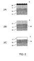
- Figure 2
- is a schematic representation of an embodiment of the method according to the present invention
- Figure 3
- is a schematic representation of an ink jet printer and fusing station.
- Example 1 describes a process of making a recording medium for use in the method according to the invention.
- Example 2 describes a result that can be achieved with the method according to the invention.
- Figure 1 is a diagram showing an inkjet printer. According to this embodiment, the printer comprises a
roller 1 used to support arecording medium 2, and to transport it along thecarriage 3. Thiscarriage 3 comprises acarrier 5 to which fourprint heads print head heating elements 9, which have been fitted to the rear of eachprint head carrier 5. The temperature of theprint heads roller 1 may rotate around its own axis as indicated by arrow A. In this manner, the receiving medium may be moved in the sub-scanning direction (often referred to as the X direction) relative to thecarrier 5, and therefore also relative to theprint heads carriage 3 may be moved in reciprocation using suitable drive mechanisms (not shown) in a direction indicated by double arrow B, parallel toroller 1. To this end, thecarrier 5 is moved across theguide rods medium 2 may be fully scanned by theprint heads print head nozzles 8 in this embodiment form one row per print head perpendicular to the axis of roller 1 (i.e. the row extends in the sub-scanning direction). In a practical embodiment of an inkjet printer, the number of ink chambers per print head will be many times greater and thenozzles 8 will be arranged over two or more rows. Each ink chamber comprises a piezo-electric converter (not shown) that may generate a pressure wave in the ink chamber so that an ink drop is ejected from the nozzle of the associated chamber in the direction of the receivingmedium 2. The converters may be actuated image-wise via an associated electrical drive circuit (not shown) by application of thecentral control unit 10. In this manner, an image made up of ink drops may be formed on receivingmedium 2. If a receivingmedium 2 is printed using such a printer where ink drops are ejected from ink chambers, this receivingmedium 2, or some of it, is (imaginarily) divided into fixed locations that form a regular field of pixel rows and pixel columns. According to one embodiment, the pixel rows are perpendicular to the pixel columns. The individual locations thus produced may each be provided with one or more ink drops. The number of locations per unit of length in the directions parallel to the pixel rows and pixel columns is referred to as the resolution of the printed image, for example indicated as 400x600 d.p.i. ("dots per inch"). By actuating a row ofprint head nozzles 8 of the inkjet printer image-wise when it is moved relative to the receivingmedium 2 as thecarrier 5 moves, an image, or some of it, made up of ink drops is formed on the receivingmedium 2, or at least in a strip as wide as the length of the nozzle row.
Roller 1 is internally provided with aradiation heater 12, which heater is configured to heat the receivingmedium 2 by heating the roller circumference which gives off its heat to the medium that contacts theroller 1. This way, the recording medium can be treated to allow the hot melt ink to pass into the medium immediately after the corresponding ink droplets have hit the surface of the recording medium. Theheater 12 is controlled by a piece of control software that is incorporated incontroller 10. In this embodiment, the software makes use of a memory which comprises numerous combinations of inks that can be used in the printer and recording media that can be used according to the present invention. Each combination is linked to a dedicated setting of the temperature of the roller, which setting is the parameter to be directly controlled in the embodied system. That is, the temperature of the roller surface is measured using a contact sensor (not shown) and compared to the pre-programmed temperature setting. Depending on the difference between the pre-programmed temperature and the measured temperature, the heater is controlled to make this difference as small as necessary. - Figure 2 is a schematical representation of the interaction of phase change ink with a recording medium according to an embodiment of the present invention. Figure 2A shows the recording medium comprising a
base layer 15 and an ink receiving layer 16 (which together form a support in the sense of the present invention) and afusible layer 17. The base layer in this case is a plain paper substrate. The ink receiving layer is a commonly used formulation of 90 % by weight of silica nanoparticles in the range of 300 to 30 nanometers in 10 % by weight of polyvinyl alcohol. The high weight fraction of particulate material with respect to the binder fraction results in a highly porous layer that has good ink retaining properties. - The fusible layer is a film of thermoplastic polymer particles (polyesther resin; Mn = 900, Tg = 55°C). These particles have an average size between 2 to 5 µm and are rod-coated on the support starting with an aqueous dispersion of the particles (10 weight % of resin in water) to provide a film of about 20µm in thickness. On top of the
fusible layer 17 lies a layer of solid phase change ink droplets (20) that has been jetted onto the surface of the recording medium.
Figure 2B represents the situation after the thermal treatment of the recording medium. The ink droplets that resided on top of the fusible layer have passed into the recording medium, in this case into theink receiving layer 16, away from the surface of the fusible layer which remained substantially unfused. In this particular case, after the ink has passed into the medium, the complete fusible layer is substantially free of ink. It is noted however that the present invention as claimed in the appended claims also compasses that only an upper layer of the fusible layer has become substantially free of ink.
Figure 2C depicts the situation after a fusing treatment of the recording medium. The fusible layer has been fused to form a closed, protective overcoat 17'. In tsi case thecomplete layer 17 has been fused to become layer 17'. It should be understood however that the present invention as claimed in the appended claims also compasses that only the upper ink free layer of the fusible layer is fused to become a protective overcoat. - Figure 3 is a schematic representation of a system for creating an image according to the present invention. On the left, the inkjet printer as elaborately described with reference to figure 1 is depicted, by showing its most important components, i.e. the internally
heated roller 1 for transporting therecording medium 2, and one of the printing heads 4. This system further comprises a fuse roller arrangement that consists ofheated roller 36 and backroller 35 which are slightly pressed together (typical line pressure 250 Newton per meter) by adequate pressure providing means (not shown). Both rollers are provided with compliant surface layers, in this example soft silicone elastomer layers (20 ShA hardness). Thetransport roller 1 is capable of transporting the printedrecording medium 2 from theink transfer position 30 to fuseposition 40. The rollers are heated to a temperature of about 140 °C which in this case (chosen resin for the fusible layer is a polyester resin with a Tg of 55°C) is adequate to heat at least an upper layer of the fusible layer such that it fuses into a continuous protective overcoat. - Example 1 describes a process of making a recording medium for use in the method according to the invention. A resin is chosen, typically having a Tg (glass transition temperature) between 50 and 70°C. As an example, the polyester resin exemplified as
resin number 3 in table 2 of international patent applicationPCT/EP2006/062614
A clean screen that is commonly used in a screen printer is placed on top of a suitable substrate, in this case Kodak Instant Dry Glossy photopaper, 190 g. It is ensured that there is good contact between the screen and the substrate by supporting the substrate and putting adequate pressure on the framework of the screen. The screen in this case is made out of mono-filaments of an inert fabric, which filaments are 40 micron wide leaving openings of 20 x 20 micrometers. - The resin dispersion is applied on the side of the screen facing away from the substrate, making sure that it is not able to wet the substrate yet. With a rubber squegee the dispersion is applied over the whole screen in one movement. It is important that the squegee does not run dry because this will cause imperfections in the coated layer. Any surplus dispersion is removed from the screen because this can interact with the substrate causing cockling or too thick layers of coating. After the coating step, the screen and substrate are left in place to allow drying. This can be done under ambient conditions. After drying the screen is removed. This method results in a recording medium having on the substrate as a support, a fusible layer consisting of dots of the polyester resin of about 40 x 40 micrometers wide and a height of about 15 to 20 micrometers in a regular pattern and a open space of a few micron in between the dots. The thickness of the dots can be varied, for example by changing the amount of resin in the dispersion.
- Other coating techniques for obtaining a fusible layer can also be successfully applied. For example, it is recognised that rod-coating techniques or cast coating techniques, both when starting from aqueous or non-aqueous media as a carrier for the fusible material, can be applied to obtain a recording media for use in the present invention.
- The invention can also be applied to parts of recording media. For example, if an overcoat is only desired for a certain smaller image of a complete image (for example, a company name above a letter, which name should appear in high gloss), a medium could be made having the fusible layer only at the location corresponding to the company name.
- In this example a result is described that can be achieved with the method according to the invention. With the screen print method described here-above ("example 1 ") four recording media are produced. For the fusible layer, four different kinds of resin are chosen, namely
resin number 3 in table 2 of international patent applicationPCT/EP2006/062614 resin number 1 in the same table of that patent application, a polyester-amide resin having a Mn (number averaged moleculair weight) of 900 and a Tg of 65°C, and a semi-crystalline polyolefine resin (available from Dow Chemical Corporation under the trade name "Engage").
These four materials are each printed with three different hot melt inks of a constitution as given in table 1. Each of these ink compositions contains a crystalline material (K), an amorphous material (A) and a gelling agent (G). The ink compositions are provided with a dye (KI), Macrolex Rot (Bayer) in the case of the ink compositions I and III, Orasol Blau (Ciba-Geigy) in the case of composition II. In addition, the three ink compositions are provided with wetting agent (V) BYK 307 (Byk Chemie). The chemical formulae of the crystalline base material (K), the amorphous binder (A) and the gelling agent (G) are given in tables 2, 3a and 1 respectively ofEP 1 067 157Table 1. Hot melt ink formulations Ink I ink II ink III K 58.3 HMDI-MEG 67.6 CYCLO-2T 66.8 HMDI-MEG A 38.1 DITRIM-50CHI 28.8 GLYPOCHI 28.6 PBPA- BuP G 3 Gel-23 2 Gel-1 4 Gel-23 KI 0.5 Macrolex Rot 1.5 Orasol Blau 0.5 Macrolex Rot V 0.1 BYK 307 0.1 BYK 307 0.1 BYK 307 - The inks are jetted at a temperature of 130°C to the recording media which are kept at a temperature of 35°C. Here-after, the recording media are transferred to an oven which is kept at 90°C. After 30 seconds the inks have passed into the media, and they are transferred to an oven kept at 110°C. Here they stay for 90 seconds which is sufficient to fuse an ink free upper layer of the recording media. Then they are brought to ambient conditions.
- To test the durability under thermal load, the printed and now "sealed" recording media are brought over to an oven at a temperature of 45°C. The image quality is inspected every 24 hours. A first relevant feature of the image quality is the gloss level (which can be measured for example using a Hunter 75° glossmeter according to TAPPI procedure T 480 OM-92). Another feature is the appearance of white spots, possibly a crystallisation effect of the crystalline material in the ink vehicle. It appears that during the first few days a slight deterioration of the gloss level occurs (typically from 70 to 60%). However, this decrease in gloss can hardly be noticed with the naked human eye. After that, the gloss level remains substantially constant, up to even 800 hours of thermal load. No white spots can be noticed wit the naked human eye.
Claims (9)
- A method of creating an image on a recording medium (2) comprising a support (15, 16) having thereon a porous fusible layer (17), using an ink composition (20) that is solid at room temperature and liquid at elevated temperature comprising the steps of:- generating droplets of the ink composition with an ink jet print head (4),- transferring the droplets of the ink composition to the surface of the fusible layer (17),- thermally treating the recording medium such that the ink transferred to fusible layer passes into the medium away from the surface of the fusible layer whilst the fusible layer remains substantially unfused,- when the ink has passed into the medium, treating the recording medium to fuse the fusible layer to become a protective overcoat (17').
- A method according to claim one characterised in that the recording medium that is used has a support comprising a base layer and thereon an ink receiving layer.
- A method according to claim 2, wherein the ink receiving layer is a micro-porous layer.
- A method according to any of the preceding claims characterised in that the fusible layer comprises a thermoplastic material.
- A method according to any of the preceding claims characterised in that the fusible layer is provided on the support via a screen printing technique.
- A method according to any of the preceding claims characterised in that ink composition that is used comprises a meltable ink vehicle consisting at least of a material that can be obtained in a crystalline phase at 25 °C.
- A method according to claim 6 characterised in that the crystalline material of the ink vehicle and the material constituting the fusible layer are substantially incompatible at 25°C.
- A method according to any of the preceding claims, characterised in that the fusible layer comprises a material having a glass transition temperature higher than 50 °C.
- A system for creating an image on a recording medium (2) comprising a support (15, 16) having thereon a porous fusible layer (17), the system comprising an ink jet print head (4) adjusted to jet droplets of an ink composition (20) that is solid at room temperature and liquid at an elevated temperature, and transfer these droplets to the surface of the fusible layer, the system optionally comprising an intermediate member for temporarily accepting the droplets of the ink composition before the said transfer to the fusible layer, and further comprising a thermal treating element (12) for thermally treating the recording medium (2) and a control arrangement (10) to control the thermal treating element such that the ink transferred to fusible layer passes into the medium away from the surface of the fusible layer whilst the fusible layer remains substantially unfused, and a transporting means (1) for transporting the recording medium (2) from an ink transfer position (30) to a fuse position (40) adjacent a fuse means (35, 36) capable of treating the recording medium to fuse the fusible layer (17) to become a protective overcoat (17').
Priority Applications (1)
| Application Number | Priority Date | Filing Date | Title |
|---|---|---|---|
| EP20070113964 EP1892115B1 (en) | 2006-08-22 | 2007-08-07 | Method of forming a phase change ink image on a self-laminating recording medium |
Applications Claiming Priority (2)
| Application Number | Priority Date | Filing Date | Title |
|---|---|---|---|
| EP06119292 | 2006-08-22 | ||
| EP20070113964 EP1892115B1 (en) | 2006-08-22 | 2007-08-07 | Method of forming a phase change ink image on a self-laminating recording medium |
Publications (2)
| Publication Number | Publication Date |
|---|---|
| EP1892115A1 true EP1892115A1 (en) | 2008-02-27 |
| EP1892115B1 EP1892115B1 (en) | 2009-12-23 |
Family
ID=38980738
Family Applications (1)
| Application Number | Title | Priority Date | Filing Date |
|---|---|---|---|
| EP20070113964 Not-in-force EP1892115B1 (en) | 2006-08-22 | 2007-08-07 | Method of forming a phase change ink image on a self-laminating recording medium |
Country Status (1)
| Country | Link |
|---|---|
| EP (1) | EP1892115B1 (en) |
Citations (7)
| Publication number | Priority date | Publication date | Assignee | Title |
|---|---|---|---|---|
| US4724025A (en) * | 1984-08-13 | 1988-02-09 | Olympus Optical Co., Ltd. | Transfer coating method |
| EP0518621A2 (en) * | 1991-06-10 | 1992-12-16 | Tektronix Inc. | Methods for processing printed substrates |
| EP1067157A1 (en) | 1999-07-09 | 2001-01-10 | Océ-Technologies B.V. | Ink composition for a meltable ink and a method of printing a substrate with such an ink composition |
| US6497480B1 (en) | 2001-09-18 | 2002-12-24 | Eastman Kodak Company | Ink jet printing method |
| US20030234841A1 (en) | 2002-06-20 | 2003-12-25 | Xerox Corporation | Phase change ink imaging component having elastomer outer layer |
| US6811253B1 (en) | 1999-08-04 | 2004-11-02 | Ilford Imaging Uk Limited | Ink jet printing method |
| US6905203B2 (en) | 2002-07-05 | 2005-06-14 | Océ-Technologies B.V. | Method of printing a receiving material with hot melt ink and an inkjet printer suitable for applying such a method |
-
2007
- 2007-08-07 EP EP20070113964 patent/EP1892115B1/en not_active Not-in-force
Patent Citations (7)
| Publication number | Priority date | Publication date | Assignee | Title |
|---|---|---|---|---|
| US4724025A (en) * | 1984-08-13 | 1988-02-09 | Olympus Optical Co., Ltd. | Transfer coating method |
| EP0518621A2 (en) * | 1991-06-10 | 1992-12-16 | Tektronix Inc. | Methods for processing printed substrates |
| EP1067157A1 (en) | 1999-07-09 | 2001-01-10 | Océ-Technologies B.V. | Ink composition for a meltable ink and a method of printing a substrate with such an ink composition |
| US6811253B1 (en) | 1999-08-04 | 2004-11-02 | Ilford Imaging Uk Limited | Ink jet printing method |
| US6497480B1 (en) | 2001-09-18 | 2002-12-24 | Eastman Kodak Company | Ink jet printing method |
| US20030234841A1 (en) | 2002-06-20 | 2003-12-25 | Xerox Corporation | Phase change ink imaging component having elastomer outer layer |
| US6905203B2 (en) | 2002-07-05 | 2005-06-14 | Océ-Technologies B.V. | Method of printing a receiving material with hot melt ink and an inkjet printer suitable for applying such a method |
Also Published As
| Publication number | Publication date |
|---|---|
| EP1892115B1 (en) | 2009-12-23 |
Similar Documents
| Publication | Publication Date | Title |
|---|---|---|
| US6332679B1 (en) | Image forming method and image forming apparatus | |
| US8546303B2 (en) | Thermal transfer sheet | |
| EP0355342A2 (en) | Substrates having a light-transmissive phase change ink printed thereon and methods for producing same | |
| JP2008213199A (en) | Heat-shrinkable laminated film, method for producing heat-shrinkable laminated film, container, method for producing container | |
| US8057031B2 (en) | Method of forming a phase change ink image on a self-laminating recording medium | |
| EP1426196B1 (en) | Sealable topcoat for porous media | |
| EP1813434B1 (en) | Thermal transfer sheet | |
| EP1708892B1 (en) | Inkjet recording element | |
| US6866384B2 (en) | Ink jet printing method | |
| JP2007512985A (en) | Plasma treatment of porous inkjet receivers. | |
| EP1892115B1 (en) | Method of forming a phase change ink image on a self-laminating recording medium | |
| US20020009576A1 (en) | Specialty microporous films and laminated media with applications in ink jet and digital printing | |
| EP1403089B1 (en) | Ink jet recording element and printing method | |
| EP1293356B1 (en) | Ink jet recording element and printing method | |
| EP1457350B1 (en) | A print medium including a heat-sealable layer | |
| US7165836B2 (en) | Method of thermally sealing the overcoat of multilayer media | |
| WO2009157990A1 (en) | Inkjet printing system | |
| JP4373253B2 (en) | Thermal transfer sheet | |
| JP2006192676A (en) | Thermal transfer sheet | |
| JP2001353967A (en) | Dye-donor element for thermal dye transfer | |
| EP1375175B1 (en) | Ink jet printing method | |
| EP1403090B1 (en) | Ink jet recording element and printing method | |
| EP2328761B1 (en) | Fusible inkjet recording media | |
| JP7192335B2 (en) | thermal transfer image receiving sheet | |
| JP4648174B2 (en) | Thermal transfer sheet |
Legal Events
| Date | Code | Title | Description |
|---|---|---|---|
| PUAI | Public reference made under article 153(3) epc to a published international application that has entered the european phase |
Free format text: ORIGINAL CODE: 0009012 |
|
| AK | Designated contracting states |
Kind code of ref document: A1 Designated state(s): AT BE BG CH CY CZ DE DK EE ES FI FR GB GR HU IE IS IT LI LT LU LV MC MT NL PL PT RO SE SI SK TR |
|
| AX | Request for extension of the european patent |
Extension state: AL BA HR MK YU |
|
| 17P | Request for examination filed |
Effective date: 20080827 |
|
| AKX | Designation fees paid |
Designated state(s): AT BE BG CH CY CZ DE DK EE ES FI FR GB GR HU IE IS IT LI LT LU LV MC MT NL PL PT RO SE SI SK TR |
|
| GRAP | Despatch of communication of intention to grant a patent |
Free format text: ORIGINAL CODE: EPIDOSNIGR1 |
|
| GRAS | Grant fee paid |
Free format text: ORIGINAL CODE: EPIDOSNIGR3 |
|
| GRAA | (expected) grant |
Free format text: ORIGINAL CODE: 0009210 |
|
| RAP1 | Party data changed (applicant data changed or rights of an application transferred) |
Owner name: OCE-TECHNOLOGIES B.V. |
|
| AK | Designated contracting states |
Kind code of ref document: B1 Designated state(s): AT BE BG CH CY CZ DE DK EE ES FI FR GB GR HU IE IS IT LI LT LU LV MC MT NL PL PT RO SE SI SK TR |
|
| REG | Reference to a national code |
Ref country code: GB Ref legal event code: FG4D |
|
| REG | Reference to a national code |
Ref country code: CH Ref legal event code: EP |
|
| REG | Reference to a national code |
Ref country code: IE Ref legal event code: FG4D |
|
| REF | Corresponds to: |
Ref document number: 602007003908 Country of ref document: DE Date of ref document: 20100204 Kind code of ref document: P |
|
| REG | Reference to a national code |
Ref country code: NL Ref legal event code: T3 |
|
| PG25 | Lapsed in a contracting state [announced via postgrant information from national office to epo] |
Ref country code: LT Free format text: LAPSE BECAUSE OF FAILURE TO SUBMIT A TRANSLATION OF THE DESCRIPTION OR TO PAY THE FEE WITHIN THE PRESCRIBED TIME-LIMIT Effective date: 20091223 Ref country code: SE Free format text: LAPSE BECAUSE OF FAILURE TO SUBMIT A TRANSLATION OF THE DESCRIPTION OR TO PAY THE FEE WITHIN THE PRESCRIBED TIME-LIMIT Effective date: 20091223 Ref country code: FI Free format text: LAPSE BECAUSE OF FAILURE TO SUBMIT A TRANSLATION OF THE DESCRIPTION OR TO PAY THE FEE WITHIN THE PRESCRIBED TIME-LIMIT Effective date: 20091223 |
|
| LTIE | Lt: invalidation of european patent or patent extension |
Effective date: 20091223 |
|
| PG25 | Lapsed in a contracting state [announced via postgrant information from national office to epo] |
Ref country code: SI Free format text: LAPSE BECAUSE OF FAILURE TO SUBMIT A TRANSLATION OF THE DESCRIPTION OR TO PAY THE FEE WITHIN THE PRESCRIBED TIME-LIMIT Effective date: 20091223 Ref country code: PL Free format text: LAPSE BECAUSE OF FAILURE TO SUBMIT A TRANSLATION OF THE DESCRIPTION OR TO PAY THE FEE WITHIN THE PRESCRIBED TIME-LIMIT Effective date: 20091223 Ref country code: LV Free format text: LAPSE BECAUSE OF FAILURE TO SUBMIT A TRANSLATION OF THE DESCRIPTION OR TO PAY THE FEE WITHIN THE PRESCRIBED TIME-LIMIT Effective date: 20091223 |
|
| PG25 | Lapsed in a contracting state [announced via postgrant information from national office to epo] |
Ref country code: AT Free format text: LAPSE BECAUSE OF FAILURE TO SUBMIT A TRANSLATION OF THE DESCRIPTION OR TO PAY THE FEE WITHIN THE PRESCRIBED TIME-LIMIT Effective date: 20091223 |
|
| PG25 | Lapsed in a contracting state [announced via postgrant information from national office to epo] |
Ref country code: BG Free format text: LAPSE BECAUSE OF FAILURE TO SUBMIT A TRANSLATION OF THE DESCRIPTION OR TO PAY THE FEE WITHIN THE PRESCRIBED TIME-LIMIT Effective date: 20100323 Ref country code: PT Free format text: LAPSE BECAUSE OF FAILURE TO SUBMIT A TRANSLATION OF THE DESCRIPTION OR TO PAY THE FEE WITHIN THE PRESCRIBED TIME-LIMIT Effective date: 20100423 Ref country code: EE Free format text: LAPSE BECAUSE OF FAILURE TO SUBMIT A TRANSLATION OF THE DESCRIPTION OR TO PAY THE FEE WITHIN THE PRESCRIBED TIME-LIMIT Effective date: 20091223 Ref country code: ES Free format text: LAPSE BECAUSE OF FAILURE TO SUBMIT A TRANSLATION OF THE DESCRIPTION OR TO PAY THE FEE WITHIN THE PRESCRIBED TIME-LIMIT Effective date: 20100403 Ref country code: RO Free format text: LAPSE BECAUSE OF FAILURE TO SUBMIT A TRANSLATION OF THE DESCRIPTION OR TO PAY THE FEE WITHIN THE PRESCRIBED TIME-LIMIT Effective date: 20091223 Ref country code: IS Free format text: LAPSE BECAUSE OF FAILURE TO SUBMIT A TRANSLATION OF THE DESCRIPTION OR TO PAY THE FEE WITHIN THE PRESCRIBED TIME-LIMIT Effective date: 20100423 |
|
| PG25 | Lapsed in a contracting state [announced via postgrant information from national office to epo] |
Ref country code: SK Free format text: LAPSE BECAUSE OF FAILURE TO SUBMIT A TRANSLATION OF THE DESCRIPTION OR TO PAY THE FEE WITHIN THE PRESCRIBED TIME-LIMIT Effective date: 20091223 Ref country code: CZ Free format text: LAPSE BECAUSE OF FAILURE TO SUBMIT A TRANSLATION OF THE DESCRIPTION OR TO PAY THE FEE WITHIN THE PRESCRIBED TIME-LIMIT Effective date: 20091223 Ref country code: BE Free format text: LAPSE BECAUSE OF FAILURE TO SUBMIT A TRANSLATION OF THE DESCRIPTION OR TO PAY THE FEE WITHIN THE PRESCRIBED TIME-LIMIT Effective date: 20091223 |
|
| PG25 | Lapsed in a contracting state [announced via postgrant information from national office to epo] |
Ref country code: CY Free format text: LAPSE BECAUSE OF FAILURE TO SUBMIT A TRANSLATION OF THE DESCRIPTION OR TO PAY THE FEE WITHIN THE PRESCRIBED TIME-LIMIT Effective date: 20091223 Ref country code: GR Free format text: LAPSE BECAUSE OF FAILURE TO SUBMIT A TRANSLATION OF THE DESCRIPTION OR TO PAY THE FEE WITHIN THE PRESCRIBED TIME-LIMIT Effective date: 20100324 |
|
| PLBE | No opposition filed within time limit |
Free format text: ORIGINAL CODE: 0009261 |
|
| STAA | Information on the status of an ep patent application or granted ep patent |
Free format text: STATUS: NO OPPOSITION FILED WITHIN TIME LIMIT |
|
| 26N | No opposition filed |
Effective date: 20100924 |
|
| PG25 | Lapsed in a contracting state [announced via postgrant information from national office to epo] |
Ref country code: DK Free format text: LAPSE BECAUSE OF FAILURE TO SUBMIT A TRANSLATION OF THE DESCRIPTION OR TO PAY THE FEE WITHIN THE PRESCRIBED TIME-LIMIT Effective date: 20091223 |
|
| PG25 | Lapsed in a contracting state [announced via postgrant information from national office to epo] |
Ref country code: IT Free format text: LAPSE BECAUSE OF FAILURE TO SUBMIT A TRANSLATION OF THE DESCRIPTION OR TO PAY THE FEE WITHIN THE PRESCRIBED TIME-LIMIT Effective date: 20091223 Ref country code: MC Free format text: LAPSE BECAUSE OF NON-PAYMENT OF DUE FEES Effective date: 20100831 |
|
| PG25 | Lapsed in a contracting state [announced via postgrant information from national office to epo] |
Ref country code: IE Free format text: LAPSE BECAUSE OF NON-PAYMENT OF DUE FEES Effective date: 20100807 |
|
| PG25 | Lapsed in a contracting state [announced via postgrant information from national office to epo] |
Ref country code: MT Free format text: LAPSE BECAUSE OF FAILURE TO SUBMIT A TRANSLATION OF THE DESCRIPTION OR TO PAY THE FEE WITHIN THE PRESCRIBED TIME-LIMIT Effective date: 20091223 |
|
| REG | Reference to a national code |
Ref country code: CH Ref legal event code: PL |
|
| PG25 | Lapsed in a contracting state [announced via postgrant information from national office to epo] |
Ref country code: LI Free format text: LAPSE BECAUSE OF NON-PAYMENT OF DUE FEES Effective date: 20110831 Ref country code: CH Free format text: LAPSE BECAUSE OF NON-PAYMENT OF DUE FEES Effective date: 20110831 |
|
| PG25 | Lapsed in a contracting state [announced via postgrant information from national office to epo] |
Ref country code: LU Free format text: LAPSE BECAUSE OF NON-PAYMENT OF DUE FEES Effective date: 20100807 Ref country code: HU Free format text: LAPSE BECAUSE OF FAILURE TO SUBMIT A TRANSLATION OF THE DESCRIPTION OR TO PAY THE FEE WITHIN THE PRESCRIBED TIME-LIMIT Effective date: 20100624 |
|
| PG25 | Lapsed in a contracting state [announced via postgrant information from national office to epo] |
Ref country code: TR Free format text: LAPSE BECAUSE OF FAILURE TO SUBMIT A TRANSLATION OF THE DESCRIPTION OR TO PAY THE FEE WITHIN THE PRESCRIBED TIME-LIMIT Effective date: 20091223 |
|
| REG | Reference to a national code |
Ref country code: FR Ref legal event code: PLFP Year of fee payment: 9 |
|
| PGFP | Annual fee paid to national office [announced via postgrant information from national office to epo] |
Ref country code: NL Payment date: 20150827 Year of fee payment: 9 |
|
| PGFP | Annual fee paid to national office [announced via postgrant information from national office to epo] |
Ref country code: GB Payment date: 20150819 Year of fee payment: 9 Ref country code: DE Payment date: 20150821 Year of fee payment: 9 |
|
| PGFP | Annual fee paid to national office [announced via postgrant information from national office to epo] |
Ref country code: FR Payment date: 20150820 Year of fee payment: 9 |
|
| REG | Reference to a national code |
Ref country code: DE Ref legal event code: R119 Ref document number: 602007003908 Country of ref document: DE |
|
| REG | Reference to a national code |
Ref country code: NL Ref legal event code: MM Effective date: 20160901 |
|
| GBPC | Gb: european patent ceased through non-payment of renewal fee |
Effective date: 20160807 |
|
| REG | Reference to a national code |
Ref country code: FR Ref legal event code: ST Effective date: 20170428 |
|
| PG25 | Lapsed in a contracting state [announced via postgrant information from national office to epo] |
Ref country code: NL Free format text: LAPSE BECAUSE OF NON-PAYMENT OF DUE FEES Effective date: 20160901 |
|
| PG25 | Lapsed in a contracting state [announced via postgrant information from national office to epo] |
Ref country code: DE Free format text: LAPSE BECAUSE OF NON-PAYMENT OF DUE FEES Effective date: 20170301 Ref country code: GB Free format text: LAPSE BECAUSE OF NON-PAYMENT OF DUE FEES Effective date: 20160807 Ref country code: FR Free format text: LAPSE BECAUSE OF NON-PAYMENT OF DUE FEES Effective date: 20160831 |