EP1892005A1 - Adhesive for syringe needle, method of adhering syringe needle, front assembly for syringe and syringe - Google Patents
Adhesive for syringe needle, method of adhering syringe needle, front assembly for syringe and syringe Download PDFInfo
- Publication number
- EP1892005A1 EP1892005A1 EP06766450A EP06766450A EP1892005A1 EP 1892005 A1 EP1892005 A1 EP 1892005A1 EP 06766450 A EP06766450 A EP 06766450A EP 06766450 A EP06766450 A EP 06766450A EP 1892005 A1 EP1892005 A1 EP 1892005A1
- Authority
- EP
- European Patent Office
- Prior art keywords
- needle
- injection needle
- adhesive
- base member
- injection
- Prior art date
- Legal status (The legal status is an assumption and is not a legal conclusion. Google has not performed a legal analysis and makes no representation as to the accuracy of the status listed.)
- Granted
Links
Images


Classifications
-
- A—HUMAN NECESSITIES
- A61—MEDICAL OR VETERINARY SCIENCE; HYGIENE
- A61M—DEVICES FOR INTRODUCING MEDIA INTO, OR ONTO, THE BODY; DEVICES FOR TRANSDUCING BODY MEDIA OR FOR TAKING MEDIA FROM THE BODY; DEVICES FOR PRODUCING OR ENDING SLEEP OR STUPOR
- A61M5/00—Devices for bringing media into the body in a subcutaneous, intra-vascular or intramuscular way; Accessories therefor, e.g. filling or cleaning devices, arm-rests
- A61M5/178—Syringes
- A61M5/28—Syringe ampoules or carpules, i.e. ampoules or carpules provided with a needle
- A61M5/284—Syringe ampoules or carpules, i.e. ampoules or carpules provided with a needle comprising means for injection of two or more media, e.g. by mixing
-
- A—HUMAN NECESSITIES
- A61—MEDICAL OR VETERINARY SCIENCE; HYGIENE
- A61M—DEVICES FOR INTRODUCING MEDIA INTO, OR ONTO, THE BODY; DEVICES FOR TRANSDUCING BODY MEDIA OR FOR TAKING MEDIA FROM THE BODY; DEVICES FOR PRODUCING OR ENDING SLEEP OR STUPOR
- A61M5/00—Devices for bringing media into the body in a subcutaneous, intra-vascular or intramuscular way; Accessories therefor, e.g. filling or cleaning devices, arm-rests
- A61M5/178—Syringes
- A61M5/31—Details
- A61M5/32—Needles; Details of needles pertaining to their connection with syringe or hub; Accessories for bringing the needle into, or holding the needle on, the body; Devices for protection of needles
- A61M5/34—Constructions for connecting the needle, e.g. to syringe nozzle or needle hub
- A61M5/349—Constructions for connecting the needle, e.g. to syringe nozzle or needle hub using adhesive bond or glues
-
- C—CHEMISTRY; METALLURGY
- C09—DYES; PAINTS; POLISHES; NATURAL RESINS; ADHESIVES; COMPOSITIONS NOT OTHERWISE PROVIDED FOR; APPLICATIONS OF MATERIALS NOT OTHERWISE PROVIDED FOR
- C09J—ADHESIVES; NON-MECHANICAL ASPECTS OF ADHESIVE PROCESSES IN GENERAL; ADHESIVE PROCESSES NOT PROVIDED FOR ELSEWHERE; USE OF MATERIALS AS ADHESIVES
- C09J163/00—Adhesives based on epoxy resins; Adhesives based on derivatives of epoxy resins
-
- A—HUMAN NECESSITIES
- A61—MEDICAL OR VETERINARY SCIENCE; HYGIENE
- A61M—DEVICES FOR INTRODUCING MEDIA INTO, OR ONTO, THE BODY; DEVICES FOR TRANSDUCING BODY MEDIA OR FOR TAKING MEDIA FROM THE BODY; DEVICES FOR PRODUCING OR ENDING SLEEP OR STUPOR
- A61M5/00—Devices for bringing media into the body in a subcutaneous, intra-vascular or intramuscular way; Accessories therefor, e.g. filling or cleaning devices, arm-rests
- A61M5/178—Syringes
- A61M5/31—Details
- A61M5/3129—Syringe barrels
- A61M2005/3132—Syringe barrels having flow passages for injection agents at the distal end of the barrel to bypass a sealing stopper after its displacement to this end due to internal pressure increase
Definitions
- the content of the denatured aliphatic epoxy resin is concretely set to about 10 to about 25 wt% and more preferably set to about 20 wt% of the total quantity of the epoxy adhesive.
- the adhesive may additionally contain bisphenol A-type epoxy resin, denatured polyamide resin and titanium oxide.
- a fourth invention concerns another syringe front-assembly.
- This syringe front-assembly comprises the injection needle 4, the needle-base member 5, the connection hub 6 and the protector cap 7.
- the injection needle 4 is fixed to the needle-base member 5, which is detachably attached to the connection hub 6.
- This connection hub 6 is provided with the connection portion 17 which is secured to the leading end of the injection cylinder 2.
- the protector cap 7 is removably fitted onto the injection needle 4 in such a manner that it covers the periphery of the injection needle 4.
- the injection needle 4 is fixed to the needle-base member 5 mutually by the method for bonding the injection needle according to the second invention.
- this front-assembly 3 and the injection cylinder 2 which has preliminarily accommodated the pharmaceutical component 13 and the dissolving or dispersing liquid in the respective chambers 11 and 12, are subjected to a sterilization treatment with dump and heat by vapor at a predetermined temperature within an aseptic room.
- the connection hub 6 has the connection portion 17 externally fitted and fixed onto the leading end of the injection cylinder 2 and a finger grip 20 is externally fitted and fixed onto a rear end of the injection cylinder 2 so as to complete the assembly of the syringe 1.
- the plunger 16 is fixed by screws to a rearward portion of the end plug 10, this plunger 16 may be removed and packed in a set as it is removed, for a product.
- the front-assembly 3 is subjected to the sterilization treatment with dump and heat by vapor of a predetermined temperature and the thus sterilized front-assembly 3 is dried.
- the pharmaceutical medicine for injection 22 is accommodated into the pharmaceutical liquid accommodating chamber 21 of the injection cylinder 2, which is hermetically sealed by the end plug 10 to complete the assembly process.
- the inspection is carried out for the appearance of the front-assembly 3 to see if any foreign matter is adhered thereto, in the same as the first embodiment.
- the front-assembly 3 is additionally provided at the leading end of the unfilled injection cylinder 2 and is subjected to the sterilization treatment. Then the pharmaceutical medicine 22 for injection is filled into the injection cylinder 2.
- the front-assembly and the filled injection cylinder may be subjected to the sterilization treatment and then assembled to each other, like the first embodiment.
- the occurrence rate of foreign matters was 0.0 to 0.5 %.
- Comparison Example 1 The viscosity of the adhesive was adjusted to 10000 mPa ⁇ s with the content of the denatured aliphatic epoxy resin falling within a range of 15 to 25 wt%. The adhesive was cured by heating at 120 degrees C for 20 mins. As a result of having measured the sterilized adhesive, the occurrence rate of foreign matters was about 1 to 15 %.
- the present invention can facilitates bonding the injection needle to the needle-base member and in addition can inhibit the occurrence of the foreign matters attributable to the adhesive to thereby enhance the yield.
- it is suitably usable, for example, to the uni-chamber prefilled syringe and the dual-chamber prefilled syringe and also to the front-assembly used therefor. Needless to say, it is applicable to other syringes.
Landscapes
- Health & Medical Sciences (AREA)
- Vascular Medicine (AREA)
- Engineering & Computer Science (AREA)
- Anesthesiology (AREA)
- Biomedical Technology (AREA)
- Heart & Thoracic Surgery (AREA)
- Hematology (AREA)
- Life Sciences & Earth Sciences (AREA)
- Animal Behavior & Ethology (AREA)
- General Health & Medical Sciences (AREA)
- Public Health (AREA)
- Veterinary Medicine (AREA)
- Chemical & Material Sciences (AREA)
- Organic Chemistry (AREA)
- Infusion, Injection, And Reservoir Apparatuses (AREA)
- Adhesives Or Adhesive Processes (AREA)
Abstract
Description
- The present invention relates to an adhesive agent used for bonding an injection needle and a method for bonding the injection needle and more particularly it concerns an adhesive agent for an injection needle and a method for bonding the injection needle, which inhibits the occurrence of foreign matters attributable to the adhesive agent so as to enhance the yield, as well as a syringe front-assembly using the same and a syringe.
- A general example of the syringes comprises a front-assembly, which is provided with an injection needle, a needle-base member, a protector cap and a connection hub, secured to a leading end of an injection cylinder (for example, see Patent Literature 1).
The connection hub has a connection portion hermetically and securely fixed to the leading end of the injection cylinder and has the needle-base member detachably attached thereto. The injection needle has a base end portion secured to the needle-base member and a protector cap is removably fitted onto the injection needle so as to cover a periphery thereof. - The base end portion of the injection needle is assuredly secured to the needle-base member and is bonded thereto with an epoxy adhesive consisting mainly of bisphenol A-type epoxy resin. More specifically, the needle-base member has the leading end portion provided with a hole for inserting the base end portion of the injection needle. The adhesive is hermetically filled into a space between the base end portion of the injection needle and the needle-base base member so as not to cause a bad appearance such as roping. Conventionally, such an adhesive has a viscosity set to about 10000 mPa · s by adjusting the content of denatured aliphatic epoxy resin.
- Although the epoxy resin adhesive agent is cured by heating, there are many cases where the needle-base member is formed from polypropylene resin and the like synthetic resin material. Adopted for the adhesive are those of the type that cures quickly at a relatively low temperature of about 100 degrees C, for example, below 120 degrees C, so that the needle-base member does not suffer from thermal deformation upon curing.
- And the injection needle and the front-assembly with this injection needle are assembled to an injection cylinder during the production process of the syringe and thereafter are subjected to a sterilization treatment with dump and heat by vapor at a temperature of, for example, 121 degrees C in an aseptic room before they are filled with injection medicine or are assembled to an injection cylinder prefilled with the injection medicine.
- Patent Literature 1: Utility Model Application Laid-Open
No. 10-211280 - The denatured aliphatic epoxy resin has a poor reactivity on curing. Even if the reaction time is extended at the above curing temperature, much non-reacted one, which occupies, for example about 20% of the whole amount, remains. Since this non-reacted denatured aliphatic epoxy resin is generally dissolved in water having a temperature of at least 70 degrees C, there is a case where it is dissolved out of the adhesive cured on conducing the vapor sterilization treatment and is condensed to become a foreign matter after the sterilization treatment, which adheres to a tip of the injection needle or an inner surface of the protector cap. The syringe with this non-reacted denatured aliphatic epoxy resin adhered thereto as a foreign matter is excluded as a product of bad appearance through an inspection treatment with the result of being not easy to improve the yield. This has become a problem when implementing the vapor sterilization treatment industrially.
- The present invention has a technical object to solve the above-mentioned problem and provide an adhesive for an injection needle and a method for bonding the injection needle, which are able to inhibit the occurrence of foreign matters attributable to the adhesive for enhancing the yield, as well as a syringe front-assembly and a syringe.
- The present invention is constructed as follows so as to accomplish the above-mentioned object, for example, if it is explained based on
Figs. 1 to 5 which show embodiments of the present invention.
More specifically, a first invention concerns an adhesive for an injection needle. The adhesive consists of an epoxy adhesive containing denatured aliphatic epoxy resin and bonds a base end portion of aninjection needle 4 to a needle-base member 5 at a leading end of aninjection cylinder 2, a viscosity of which is at least about 20000 mPa·s. - Here, like the viscosity of "about 20000", the word "about" attached to a numerical value in the recitation of the specification and claims includes an allowable difference of ± 5%.
- According to the first invention, the viscosity is as high as about 20000 mPa · s. Consequently, it suffices if the denatured aliphatic epoxy resin is contained in a small quantity with the result of alleviating the non-reacted denatured aliphatic epoxy resin residual in the adhesive after it has cured.
- It is sufficient if the adhesive has the viscosity of at least about 20000 mPa · s. But when it is excessively high, there is a likelihood that the excessively high viscosity reduces the workability on filling the adhesive. For this reason, it is preferably set to not more than about 40000 mPa · s, more preferably not more than about 30000 mPa · s. This enables the adhesive to be easily filled into a space between the injection needle and the needle-base member without causing the bad appearance because of roping.
- The content of the denatured aliphatic epoxy resin is concretely set to about 10 to about 25 wt% and more preferably set to about 20 wt% of the total quantity of the epoxy adhesive.
Further, the adhesive may additionally contain bisphenol A-type epoxy resin, denatured polyamide resin and titanium oxide. - A second invention relates to a method for bonding an injection needle, more specifically a method for bonding an
injection needle 4 to a needle-base member 5 at a leading end of aninjection cylinder 2 with anepoxy adhesive 19. Theadhesive 19 is filled into a space between theinjection needle 4 and the needle-base member 5 and then is heated at a temperature of at least about 130 degrees C to cure it. - According to the second invention, the curing temperature is set to be as high as at least about 130 degrees C. Therefore, even if the denatured aliphatic epoxy resin of poor reactivity is contained, the polymerization reaction is accelerated to result in alleviating non-reacted denatured aliphatic epoxy resin residual in the adhesive after curing.
In this case, the adhesive may have a viscosity as low as, for example, about 10000 mPa·s and therefore can be readily filled into the space between the injection needle and the needle-base member without causing the bad appearance such as roping. - It is required to maintain the heating temperature for curing the adhesive, namely the curing temperature at a temperature lower than a softening temperature of the needle-base member. In consequence, if this needle-base member comprises polypropylene resin or the other synthetic resin material which softens, for example, at about 160 degrees C, the curing temperature is preferably set to not more than about 140 degrees C and more preferably to about 130 degrees C.
However, this curing temperature is satisfactory as far as it does not exert bad influence on the injection needle, the needle-base member or the adhesive. For instance, when the needle-base member is formed from a material of excellent heat resistance such as stainless steel, the curing temperature can be set to a higher one, for example, about 150 degrees C so as to reduce the quantity of the residual non-reacted denatured aliphatic epoxy resin. - The heating time for curing purpose is sufficient as long as the epoxy resin is fully cured. Concretely, it is set to about 5 to about 30 mins. and more preferably to about 10 to about 20 mins. Short heating time may cause a fear of not only increasing the residual amount of non-reacted substance but also insufficiently curing the epoxy resin. This is because on one hand, once the epoxy resin has sufficiently cured, even if the heating time is excessively extended, it is difficult to more reduce the residual amount of the non-reacted substance and further the efficiency of the curing treatment is decreased.
- The epoxy adhesive concretely may include bisphenol A-type epoxy resin, denatured aliphatic epoxy resin, denatured polyamide resin and titanium oxide. In this case, although the content of the denatured aliphatic epoxy resin is not limited to specific numerical value, it is usually set to about 10 to about 25 wt% and more preferably to not more than about 20 wt%.
- Besides, a third invention concerns a syringe front-assembly. This syringe front-assembly comprises the
injection needle 4, the needle-base member 5, aconnection hub 6 and aprotector cap 7. Theinjection needle 4 is fixed to the needle-base member 5, which is detachably attached to theconnection hub 6. Thisconnection hub 6 is provided with aconnection portion 17 which is secured to a leading end of theinjection cylinder 2. Theprotector cap 7 is removably fitted onto theinjection needle 4 in such a manner that it covers a periphery of theinjection needle 4. Theinjection needle 4 is fixed to the needle-base member 5 mutually with theadhesive 19 for injection needle according to the first invention. - Additionally, a fourth invention concerns another syringe front-assembly. This syringe front-assembly comprises the
injection needle 4, the needle-base member 5, theconnection hub 6 and theprotector cap 7. Theinjection needle 4 is fixed to the needle-base member 5, which is detachably attached to theconnection hub 6. Thisconnection hub 6 is provided with theconnection portion 17 which is secured to the leading end of theinjection cylinder 2. Theprotector cap 7 is removably fitted onto theinjection needle 4 in such a manner that it covers the periphery of theinjection needle 4. Theinjection needle 4 is fixed to the needle-base member 5 mutually by the method for bonding the injection needle according to the second invention. - A fifth invention relates to a syringe. This
injection cylinder 2 has a leading end which is additionally provided with a needle-base member 5. Theinjection needle 4 is fixed to the needle-base member 5 and theprotector cap 7 is removably fitted onto theinjection needle 4 so that it covers the periphery of theinjection needle 4. Theinjection needle 4 is mutually secured to the needle-base member 5 with the adhesive 19 for injection needle according to the first invention. - A sixth invention concerns a syringe which comprises an
injection cylinder 2. Thisinjection cylinder 2 has a leading end which is additionally provided with the needle-base member 5. Theinjection needle 4 is fixed to the needle-base member 5 and theprotector cap 7 is removably fitted onto theinjection needle 4 so that it covers the periphery of theinjection needle 4. Theinjection needle 4 is mutually secured to the needle-base member 5 by the method for bonding the injection needle according to the second invention. - The above-mentioned syringe is not limited to those of a specific shape or structure but may be, for example, a uni-chamber prefilled syringe, a dual-chamber prefilled syringe or an unfilled syringe.
- Since the present invention is constituted and functions as mentioned above, it offers the following effects.
- According to the first invention, the adhesive has the viscosity set to at least about 20000 mPa · s. Therefore, it contains only a small quantity of denatured aliphatic epoxy resin to result in the possibility of alleviating the non-reacted denatured aliphatic epoxy resin residual after it has been cured.
Further, according to the second invention, since the curing temperature is set to a temperature as high as at least about 130 degrees C, even if the adhesive contains the denatured aliphatic epoxy resin, it is possible to sufficiently accelerate the reaction and reduce the non-reacted denatured aliphatic epoxy resin remaining after it has been cured. -
- [
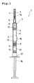
Fig. 1 ] is a sectional view of a dual-chamber prefilled syringe showing a first embodiment of the present invention; - [
Fig. 2 ] is an enlarged sectional view of a front-assembly for the syringe of the first embodiment; - [
Fig. 3 ] is a sectional view of a uni-chamber prefilled syringe showing a second embodiment of the present invention; - [
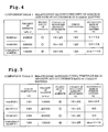
Fig.4 ] is Comparison Table 1 showing the viscosity of the adhesive and the occurrence rate of the foreign matters; and - [
Fig. 5 ] is Comparison Table 2 showing a relationship between the curing temperature of the adhesive and the occurrence rate of the foreign matters. -
- 1...syringe (dual-chamber prefilled syringe or uni-chamber prefilled syringe)
- 2...injection cylinder
- 3...syringe front-assembly
- 4...injection needle
- 5...needle-base member
- 6...connection hub
- 7...protector cap
- 17...connection portion
- 19...adhesive for injection needle (epoxy adhesive)
- Hereafter, an explanation is given for the embodiments of the present invention based on the drawings.
Figs. 1 and2 show a first embodiment of the present invention.Fig. 1 is a sectional view of a dual-chamber prefilled syringe andFig. 2 is an enlarged sectional view of a syringe front-assembly. - As shown in
Fig. 1 , thissyringe 1 comprises aninjection cylinder 2 having a leading end to which a syringe front-assembly 3 is secured. This syringe front-assembly 3 is provided with aninjection needle 4, a needle-base member 5, aconnection hub 6 and aprotector cap 7. - The
injection cylinder 2 has an interior area partitioned into a frontfirst chamber 11 and a rearsecond chamber 12 by afront plug 8, amiddle plug 9 and anend plug 10. Thefirst chamber 11 accommodatespowder pharmaceutical component 13 and thesecond chamber 12 contains dissolving liquid or dispersingliquid 14. Further, abypass 15 projects from a side wall of theinjection cylinder 2. If theend plug 10 is advanced by aplunger 16, themiddle plug 9 also advances. And when themiddle plug 9 has reached a position where thebypass 15 is formed, thefirst chamber 11 and the second chamber communicate with each other through thebypass 15, thereby enabling the dissolvingliquid 14 to flow into the first chamber so as to dissolve or disperse thepharmaceutical component 13. - The
connection hub 6 is provided with aconnection portion 17, which is externally fitted onto the leading end of theinjection cylinder 2 for hermetical and assured securing purpose.
As shown inFigs. 1 and2 , theconnection hub 6 has a leading end to which the needle-base member 5 is detachably attached by screws. The needle-base member 5 has a leading end perforated to provide aninsertion hole 18. Theinjection needle 4 has its base end portion inserted through thishole 18 so as to assuredly fix it to the needle-base member 5 with anepoxy adhesive 19. Besides, theprotector cap 7 is detachably attached to the needle-base member 5 in such a manner that it covers a periphery of theinjection needle 4. - The
epoxy adhesive 19 consists of compounds that cure quickly at a low temperature. Concretely it contains bisphenol A-type epoxy resin as a main component and in addition denatured aliphatic epoxy resin, denatured polyamide resin and titanium oxide. The viscosity of this adhesive is adjusted within a range of about 10000 to about 40000 mPa · s by the content of the denatured aliphatic epoxy resin. However, it is preferable to increase the viscosity by reducing the content of the denatured aliphatic epoxy resin. Theseepoxy adhesives 19 are cured by heating up to at least about 120 degrees C, preferably at least about 130 degrees C. - Next, an explanation is given for the procedures of sterilization treatment carried out during the assembly process of the
syringe 1.
Theinjection needle 4 is preliminarily bonded to the needle-base member 5 with anepoxy adhesive 19. This needle-base member 5 is secured to the leading end of theconnection hub 6 by screws and theprotector cap 7 is fitted around theinjection needle 4 so as to assembly the syringe front-assembly 3 as shown inFig. 2 . - Subsequently, this front-
assembly 3 and theinjection cylinder 2, which has preliminarily accommodated thepharmaceutical component 13 and the dissolving or dispersing liquid in therespective chambers connection hub 6 has theconnection portion 17 externally fitted and fixed onto the leading end of theinjection cylinder 2 and afinger grip 20 is externally fitted and fixed onto a rear end of theinjection cylinder 2 so as to complete the assembly of thesyringe 1. InFig. 1 , although theplunger 16 is fixed by screws to a rearward portion of theend plug 10, thisplunger 16 may be removed and packed in a set as it is removed, for a product. - An inspection is performed for the appearance of the
syringe 1 to see if any foreign matter is adhered to the leading end of theinjection needle 4 and an inner surface of theprotector cap 7 after the sterilization treatment or the assembly process has completed. -
Fig. 3 shows a second embodiment of the present invention and is a sectional view of a uni-chamber prefilled syringe.
As for thissyringe 1, itsinjection cylinder 2 has an interior area partitioned hermetically from an exterior area by thefront plug 8 and theend plug 10 as a chamber accommodating pharmaceutical liquid 21, which accommodatespharmaceutical medicine 22 for injection.
Regarding thesyringe 1 of the second embodiment, theinjection cylinder 2 has a front end additionally provided with a front-assembly 3. This front-assembly 3 is provided with theinjection needle 4, the needle-base member 5, theconnection hub 6 and theprotector cap 7. Theinjection needle 4 is securely fixed to the needle-base member 5 with theepoxy adhesive 19. And other constructions are the same as those in the first embodiment. Therefore, the explanation therefor is omitted. - The
syringe 1 is subjected to the sterilization treatment in the assembly process through the following procedures.
First, the front-assembly 3 has been prepared like the first embodiment. The thus prepared front-assembly 3 has theconnection hub 6 externally fitted and fixed onto the leading end of theunfilled injection cylinder 2 and afinger grip 20 is externally fitted and fixed onto a rear end of theinjection cylinder 2. - Next, in this state, the front-
assembly 3 is subjected to the sterilization treatment with dump and heat by vapor of a predetermined temperature and the thus sterilized front-assembly 3 is dried. Then the pharmaceutical medicine forinjection 22 is accommodated into the pharmaceuticalliquid accommodating chamber 21 of theinjection cylinder 2, which is hermetically sealed by theend plug 10 to complete the assembly process. After the completion of the sterilization treatment or the assembly process, the inspection is carried out for the appearance of the front-assembly 3 to see if any foreign matter is adhered thereto, in the same as the first embodiment. - It is to be noted that in this second embodiment, the front-
assembly 3 is additionally provided at the leading end of theunfilled injection cylinder 2 and is subjected to the sterilization treatment. Then thepharmaceutical medicine 22 for injection is filled into theinjection cylinder 2. However, according to the present invention, in the case of the uni-chamber prefilled syringe, needless to say, the front-assembly and the filled injection cylinder may be subjected to the sterilization treatment and then assembled to each other, like the first embodiment. - Next, the injection needle and the needle-base member were mutually bonded by differentiating the bonding conditions and then were subjected to the sterilization treatment. Subsequently, measurements were made by eyes and enlarged observation for the occurrence of foreign matters attributable to the adhesive in each case.
The combination ratio of the used adhesive is 35 to 50 wt% of bisphenol A-type epoxy resin, 10 to 25 wt% of denatured aliphatic epoxy resin and 10 to 20 wt% of titanium oxide.
As for the evaluation about the filling characteristics, it has been judged by eyes as to whether or not there occurs any bad appearance such as roping. Those without any bad appearance are marked by circle (○) and those excellent in bonding workability are marked by double circle (⊚).
The sterilization treatment was conducted by applying thermal load of at least 20 mins. at a temperature of 121 degrees C. After having sterilized, the sterilized object was dried by repeating vacuum and abdominal pressure while warming the interior area of the aseptic room. - (1) Relationship between the viscosity of the adhesive and the occurrence rate of foreign matters.
Example 1... The viscosity of the adhesive was adjusted to 20000 mPa · s with the content of the denatured aliphatic epoxy resin falling within a range of 15 to 25 wt%. The adhesive was cured by heating at 120 degrees C for 20 mins.
As a result of having measured the sterilized adhesive, the occurrence rate of foreign matters was 0.1 to 1.2 %.
Example 2... The viscosity of the adhesive was adjusted to 30000 mPa · s with the content of the denatured aliphatic epoxy resin falling within a range of 10 to 20 wt%. The adhesive was cured by heating at 120 degrees C for 20 mins.
As a result of having measured the sterilized adhesive, the occurrence rate of foreign matters was 0.0 to 0.5 %.
Comparison Example 1... The viscosity of the adhesive was adjusted to 10000 mPa·s with the content of the denatured aliphatic epoxy resin falling within a range of 15 to 25 wt%. The adhesive was cured by heating at 120 degrees C for 20 mins.
As a result of having measured the sterilized adhesive, the occurrence rate of foreign matters was about 1 to 15 %. - Comparison Table 1 in
Fig. 4 indicates the measurement results of the respective Examples and the Comparison Example 1.
Apparently from these measurement results, it has been found that even higher viscosity of the adhesive did not obstruct the bonding workability between the injection needle and the needle-base member and that the occurrence rate of the foreign matters attributable to the adhesive could be greatly reduced to thereby largely enhance the yield by decreasing the content of the denatured aliphatic epoxy resin and increasing the viscosity of the adhesive. - (2) Relationship between the curing temperature of the adhesive and the occurrence rate of foreign matters.
Example 3... The viscosity of the adhesive was adjusted to 10000 mPa · s with the content of the denatured aliphatic epoxy resin falling within a range of 15 to 25 wt%. The adhesive was cured by heating at 130 degrees C for 20 mins.
As a result of having measured the sterilized adhesive, the occurrence rate of foreign matters was 0.0 to 0.3 %.
Example 4... The viscosity of the adhesive was adjusted to 20000 mPa · s with the content of the denatured aliphatic epoxy resin falling within a range of 15 to 25 wt%. The adhesive was cured by heating at 130 degrees C for 20 mins.
As a result of having measured the sterilized adhesive, no foreign matter occurred.
Example 5... The viscosity of the adhesive was adjusted to 30000 mPa · s with the content of the denatured aliphatic epoxy resin falling within a range of 10 to 20 wt%. The adhesive was cured by heating at 130 degrees C for 20 mins.
As a result of having measured the sterilized adhesive, no foreign matter occurred. - Comparison Table 2 in
Fig. 5 indicates the measurement results of the respective Examples and the Comparison Example 1.
Apparently from the comparison of Example 3 with Comparison Example as to the measurement results, it has been found that even with the same content of the denatured aliphatic epoxy resin and the same viscosity of the adhesive, a higher curing temperature could largely alleviate the occurrence rate of the foreign matters attributable to the adhesive, thereby greatly enhancing the yield.
Further, apparently from the comparison of Examples 4 and 5 with Examples 1 and 2 as well as with Comparison Example 1, it has been found that it was possible to more alleviate the occurrence rate of the foreign matters to thereby more greatly enhance the yield by decreasing the content of denatured aliphatic epoxy resin and increasing the curing temperature. - The shape, dimension, structure, material of the syringe and of the front-assembly as well as the combined components, the combination ratio and the curing conditions of the adhesive, and the conditions of the sterilization treatment were only exemplified so as to realize the technical idea of the present invention and therefore various modifications can be added thereto within a scope of claims of the present invention. For instance, the needle-base member may be formed from stainless steel. As regards the curing temperature and heating time of the adhesive as well as the temperature and heating time of the sterilization treatment, they are not limited to those recited in Examples. Further, needless to say, the pharmaceutical medicine for injection to be filled into the injection cylinder is not limited to a specific pharmaceutical product.
- The present invention can facilitates bonding the injection needle to the needle-base member and in addition can inhibit the occurrence of the foreign matters attributable to the adhesive to thereby enhance the yield. In consequence, it is suitably usable, for example, to the uni-chamber prefilled syringe and the dual-chamber prefilled syringe and also to the front-assembly used therefor. Needless to say, it is applicable to other syringes.
Claims (15)
- An adhesive for injection needle comprising an epoxy adhesive which contains denatured aliphatic epoxy resin, the adhesive bonding a base end portion of an injection needle (4) to a needle-base member (5) at a leading end of an injection cylinder (2) and having a viscosity of at least about 20000 mPa · s.
- The adhesive for injection needle as set forth in claim 1, wherein the viscosity is not more than about 40000 mPa · s.
- The adhesive for injection needle as set forth in claim 1 or 2, wherein the content of the denatured aliphatic epoxy resin is about 10 to about 25 wt%.
- The adhesive for injection needle as set forth in claim 3, wherein the content of the denatured aliphatic epoxy resin is not more than about 20 wt%.
- The adhesive for injection needle as set forth in any one of claims 1 to 4 which further includes bisphenol A-type epoxy resin, denatured polyamide resin and titanium oxide.
- A method for bonding an injection needle (4) to a needle-base member (5) at a leading end of an injection cylinder (2) with an epoxy adhesive (19) comprising:filling the adhesive (19) into a space between the injection needle (4) and the needle-base member (5); and thenheating the adhesive (19) up to a temperature of at least about 130 degrees C to cure it.
- The method for bonding the injection needle as set forth in claim 6, wherein the heating temperature is not more than about 140 degrees C.
- The method for bonding the injection needle as set forth in claim 6 or 7, wherein the heating time for curing is about 5 to about 30 mins.
- The method for bonding the injection needle as set forth in any one of claims 6 to 8, wherein the adhesive (19) includes bisphenol A-type epoxy resin, denatured aliphatic epoxy resin, denatured polyamide resin and titanium oxide.
- The method for bonding the injection needle as set forth in claim 9, wherein the content of the denatured aliphatic epoxy resin is about 10 to about 25 wt%.
- The method for bonding the injection needle as set forth in claim 10, wherein the content of the denatured aliphatic epoxy resin is not more than about 20 wt%.
- A syringe front-assembly comprising an injection needle (4), a needle-base member (5), a connection hub (6) and a protector cap (7),
the injection needle (4) being secured to the needle-base member (5),
the needle-base member (5) being detachably attached to the connection hub (6),
the connection hub (6) being provided with a connection portion (17) which is secured to the leading end of an injection cylinder (2),
the protector cap (7) being removably fitted onto the injection needle (4) in such a manner that it covers a periphery of the injection needle (4), wherein
the injection needle (4) and the needle-base member (5) are fixed to each other with the adhesive for injection needle (19) as set forth in any one of claims 1 to 5. - A syringe front-assembly comprising an injection needle (4), a needle-base member (5), a connection hub (6) and a protector cap (7),
the injection needle (4) being secured to the needle-base member (5),
the needle-base member (5) being detachably attached to the connection hub (6),
the connection hub (6) being provided with a connection portion (17) which is secured to the leading end of an injection cylinder (2),
the protector cap (7) being removably fitted onto the injection needle (4) in such a manner that it covers a periphery of the injection needle (4), wherein
the injection needle (4) and the needle-base member (5) are fixed to each other by the method for bonding the injection needle as set forth in any one of claims 6 to 11. - A syringe comprising an injection cylinder (2) which has a leading end additionally provided with a needle-base member (5), the injection needle (4) being fixed to the needle-base member (5), a protector cap being removably fitted onto the injection needle (4) in such a manner that it covers a periphery of the injection needle (4), wherein
the injection needle (4) and the needle-base member (5) are fixed to each other with the adhesive for injection needle (19) as set forth in any one of claims 1 to 5. - A syringe comprising an injection cylinder (2) which has a leading end additionally provided with a needle-base member (5), the injection needle (4) being fixed to the needle-base member (5), a protector cap being removably fitted onto the injection needle (4) in such a manner that it covers a periphery of the injection needle (4), wherein
the injection needle (4) and the needle-base member (5) are fixed to each other by the method for bonding the injection needle as set forth in any one of claims 6 to 11.
Applications Claiming Priority (2)
| Application Number | Priority Date | Filing Date | Title |
|---|---|---|---|
| JP2005165083 | 2005-06-06 | ||
| PCT/JP2006/311213 WO2006132176A1 (en) | 2005-06-06 | 2006-06-05 | Adhesive for syringe needle, method of adhering syringe needle, front assembly for syringe and syringe |
Publications (3)
| Publication Number | Publication Date |
|---|---|
| EP1892005A1 true EP1892005A1 (en) | 2008-02-27 |
| EP1892005A4 EP1892005A4 (en) | 2012-06-20 |
| EP1892005B1 EP1892005B1 (en) | 2013-09-25 |
Family
ID=37498377
Family Applications (1)
| Application Number | Title | Priority Date | Filing Date |
|---|---|---|---|
| EP06766450.8A Not-in-force EP1892005B1 (en) | 2005-06-06 | 2006-06-05 | Adhesive for syringe needle, method of adhering syringe needle, front assembly for syringe and syringe |
Country Status (6)
| Country | Link |
|---|---|
| US (1) | US7967796B2 (en) |
| EP (1) | EP1892005B1 (en) |
| JP (1) | JPWO2006132176A1 (en) |
| CA (1) | CA2610562C (en) |
| ES (1) | ES2438737T3 (en) |
| WO (1) | WO2006132176A1 (en) |
Cited By (1)
| Publication number | Priority date | Publication date | Assignee | Title |
|---|---|---|---|---|
| EP2123307A1 (en) * | 2008-05-20 | 2009-11-25 | Hexal Ag | Method for reducing leachables and extractables in syringes |
Families Citing this family (3)
| Publication number | Priority date | Publication date | Assignee | Title |
|---|---|---|---|---|
| CA3003689C (en) | 2015-11-05 | 2023-10-10 | Tsk Laboratory Europe B.V. | Method for connecting two objects using a polymer composition and a system, for use in a cosmetic procedure |
| RU2742129C1 (en) | 2017-09-08 | 2021-02-02 | Самьянг Байофармасьютикалз Корпорейшн | Assembly of sealant syringe |
| DE102019108583B4 (en) * | 2019-04-02 | 2023-02-09 | Gerresheimer Regensburg Gmbh | Method of connecting a first component to a second component |
Family Cites Families (19)
| Publication number | Priority date | Publication date | Assignee | Title |
|---|---|---|---|---|
| US3430627A (en) * | 1963-06-10 | 1969-03-04 | Owens Illinois Inc | Hypodermic needle |
| JPS6038767B2 (en) * | 1978-07-26 | 1985-09-03 | 富士写真フイルム株式会社 | magnetic recording medium |
| JPS5714437A (en) * | 1980-06-30 | 1982-01-25 | Hakko Denki Seisakusho:Kk | Production of injection needle and needle base thereof |
| JPS59204675A (en) * | 1983-05-04 | 1984-11-20 | Kanegafuchi Chem Ind Co Ltd | Heat-resistant adhesive |
| US4808639A (en) * | 1986-07-16 | 1989-02-28 | Production Previews, Inc. | Liquid curable adhesive composition comprising a polyester resin and a microencapsulated peroxide curing agent |
| US4795445A (en) * | 1987-03-27 | 1989-01-03 | Becton, Dickinson And Company | Hub configuration |
| JPH0639037A (en) * | 1992-07-22 | 1994-02-15 | Three Bond Co Ltd | Adhesive composition for fixing injection needle |
| JPH06225940A (en) * | 1993-02-02 | 1994-08-16 | Terumo Corp | Needle |
| US5358491A (en) * | 1993-09-13 | 1994-10-25 | Sterling Winthrop Inc. | Cartridge-needle unit having retractable needle |
| JPH07145225A (en) * | 1993-11-22 | 1995-06-06 | Nissan Motor Co Ltd | Adhesive epoxy resin composition |
| JP3765330B2 (en) * | 1996-07-09 | 2006-04-12 | 日立化成工業株式会社 | Curable composition, method for producing the same, and method for producing the cured product |
| JP3940455B2 (en) | 1997-01-30 | 2007-07-04 | 武田薬品工業株式会社 | Two-chamber syringe |
| JPH11302358A (en) * | 1998-04-22 | 1999-11-02 | Tomoegawa Paper Co Ltd | Photocurable resin composition |
| JP2002146321A (en) * | 2000-11-16 | 2002-05-22 | Hitachi Chem Co Ltd | Adhesive composition, adhesive member using the adhesive composition, substrate for mounting semiconductor, and semiconductor device |
| US6746428B2 (en) * | 2001-02-21 | 2004-06-08 | Becton, Dickinson And Company | High temperature dry heat sterilizable syringe barrel and needle cannula assembly |
| JP2004099833A (en) * | 2002-09-12 | 2004-04-02 | Three M Innovative Properties Co | Thermosetting adhesive composition, film adhesive, and semiconductor device |
| JP4300790B2 (en) * | 2002-07-18 | 2009-07-22 | 住友金属鉱山株式会社 | Thermosetting optical adhesive, optical isolator element and optical isolator to which this adhesive is applied |
| JP4405745B2 (en) * | 2003-04-22 | 2010-01-27 | 株式会社カネカ | Curable adhesive composition |
| JP2005307037A (en) * | 2004-04-22 | 2005-11-04 | Nagase Chemtex Corp | Film-like epoxy resin composition |
-
2006
- 2006-06-05 CA CA2610562A patent/CA2610562C/en not_active Expired - Fee Related
- 2006-06-05 JP JP2007520089A patent/JPWO2006132176A1/en active Pending
- 2006-06-05 WO PCT/JP2006/311213 patent/WO2006132176A1/en not_active Ceased
- 2006-06-05 US US11/921,574 patent/US7967796B2/en not_active Expired - Fee Related
- 2006-06-05 EP EP06766450.8A patent/EP1892005B1/en not_active Not-in-force
- 2006-06-05 ES ES06766450.8T patent/ES2438737T3/en active Active
Cited By (4)
| Publication number | Priority date | Publication date | Assignee | Title |
|---|---|---|---|---|
| EP2123307A1 (en) * | 2008-05-20 | 2009-11-25 | Hexal Ag | Method for reducing leachables and extractables in syringes |
| WO2009141397A1 (en) * | 2008-05-20 | 2009-11-26 | Hexal Ag | Method for reducing leachables and extractables in syringes |
| US8720165B2 (en) | 2008-05-20 | 2014-05-13 | Hexal Ag | Method for reducing leachables and extractables in syringes |
| US9895497B2 (en) | 2008-05-20 | 2018-02-20 | Hexal Ag | Method for reducing leachables and extractables in syringes |
Also Published As
| Publication number | Publication date |
|---|---|
| ES2438737T3 (en) | 2014-01-20 |
| CA2610562A1 (en) | 2006-12-14 |
| WO2006132176A1 (en) | 2006-12-14 |
| US7967796B2 (en) | 2011-06-28 |
| CA2610562C (en) | 2013-12-24 |
| EP1892005B1 (en) | 2013-09-25 |
| US20090209919A1 (en) | 2009-08-20 |
| EP1892005A4 (en) | 2012-06-20 |
| JPWO2006132176A1 (en) | 2009-01-08 |
Similar Documents
| Publication | Publication Date | Title |
|---|---|---|
| US11786664B2 (en) | Prefilled container systems | |
| CA2865274C (en) | Retractable needle safety syringes | |
| JP5230023B2 (en) | Applicators and methods of use for multi-component formulations, etc. | |
| Stamatacos et al. | Cementation of indirect restorations: an overview of resin cements. | |
| CA2457186C (en) | Prefilled syringe or carpule for medicinal purposes | |
| JP7648346B2 (en) | Fluid prefillable or prefilled container and cannula assembly and closure system for a fluid prefillable or prefilled container - Patents.com | |
| DK2167169T4 (en) | Tokammerkarpule with accessories | |
| US5573042A (en) | Process for the preparation of prefilled syringes without residual gas bubbles | |
| CN1744871A (en) | Device and procedure for the extemporaneous preparation of an individual quantity of sterile liquid | |
| CA2502888A1 (en) | Drug cartridge assembly and method of manufacture | |
| US20150174339A1 (en) | Retractable needle adapters and safety syringes | |
| WO2012115022A1 (en) | Device and kit for mixing three components | |
| TW200916138A (en) | Two-chamber carpule | |
| EP1075293A1 (en) | Syringe assembly | |
| JP7044708B2 (en) | How to fill a customized syringe | |
| EP1892005B1 (en) | Adhesive for syringe needle, method of adhering syringe needle, front assembly for syringe and syringe | |
| JP2017538463A (en) | Syringe and syringe preparation method | |
| US20110174647A1 (en) | Combined container-syringe | |
| US9833572B2 (en) | Modular dual chamber syringe system | |
| KR20230161529A (en) | Mixing vial | |
| EP1749500A1 (en) | Nozzle for dental composition | |
| US10098812B2 (en) | Multi-component container | |
| US20210196254A1 (en) | Medical adhesive applicator | |
| WO2025229422A1 (en) | Application device for storing and dispensing a dental material, process for producing and use thereof | |
| CN224008811U (en) | Explosion-proof prefilled syringe |
Legal Events
| Date | Code | Title | Description |
|---|---|---|---|
| PUAI | Public reference made under article 153(3) epc to a published international application that has entered the european phase |
Free format text: ORIGINAL CODE: 0009012 |
|
| 17P | Request for examination filed |
Effective date: 20080107 |
|
| AK | Designated contracting states |
Kind code of ref document: A1 Designated state(s): AT BE BG CH CY CZ DE DK EE ES FI FR GB GR HU IE IS IT LI LT LU LV MC NL PL PT RO SE SI SK TR |
|
| DAX | Request for extension of the european patent (deleted) | ||
| DAX | Request for extension of the european patent (deleted) | ||
| A4 | Supplementary search report drawn up and despatched |
Effective date: 20120523 |
|
| RIC1 | Information provided on ipc code assigned before grant |
Ipc: A61M 5/34 20060101AFI20120516BHEP Ipc: C09J 163/00 20060101ALI20120516BHEP |
|
| REG | Reference to a national code |
Ref country code: DE Ref legal event code: R079 Ref document number: 602006038589 Country of ref document: DE Free format text: PREVIOUS MAIN CLASS: A61M0005340000 Ipc: A61M0005280000 |
|
| GRAP | Despatch of communication of intention to grant a patent |
Free format text: ORIGINAL CODE: EPIDOSNIGR1 |
|
| RIC1 | Information provided on ipc code assigned before grant |
Ipc: A61M 5/34 20060101ALI20130304BHEP Ipc: A61M 5/28 20060101AFI20130304BHEP Ipc: C09J 163/00 20060101ALI20130304BHEP |
|
| INTG | Intention to grant announced |
Effective date: 20130411 |
|
| GRAS | Grant fee paid |
Free format text: ORIGINAL CODE: EPIDOSNIGR3 |
|
| GRAA | (expected) grant |
Free format text: ORIGINAL CODE: 0009210 |
|
| AK | Designated contracting states |
Kind code of ref document: B1 Designated state(s): AT BE BG CH CY CZ DE DK EE ES FI FR GB GR HU IE IS IT LI LT LU LV MC NL PL PT RO SE SI SK TR |
|
| REG | Reference to a national code |
Ref country code: GB Ref legal event code: FG4D |
|
| REG | Reference to a national code |
Ref country code: CH Ref legal event code: EP |
|
| REG | Reference to a national code |
Ref country code: AT Ref legal event code: REF Ref document number: 633480 Country of ref document: AT Kind code of ref document: T Effective date: 20131015 |
|
| REG | Reference to a national code |
Ref country code: IE Ref legal event code: FG4D |
|
| REG | Reference to a national code |
Ref country code: DE Ref legal event code: R096 Ref document number: 602006038589 Country of ref document: DE Effective date: 20131121 |
|
| REG | Reference to a national code |
Ref country code: ES Ref legal event code: FG2A Ref document number: 2438737 Country of ref document: ES Kind code of ref document: T3 Effective date: 20140120 |
|
| PG25 | Lapsed in a contracting state [announced via postgrant information from national office to epo] |
Ref country code: LT Free format text: LAPSE BECAUSE OF FAILURE TO SUBMIT A TRANSLATION OF THE DESCRIPTION OR TO PAY THE FEE WITHIN THE PRESCRIBED TIME-LIMIT Effective date: 20130925 Ref country code: SE Free format text: LAPSE BECAUSE OF FAILURE TO SUBMIT A TRANSLATION OF THE DESCRIPTION OR TO PAY THE FEE WITHIN THE PRESCRIBED TIME-LIMIT Effective date: 20130925 |
|
| REG | Reference to a national code |
Ref country code: AT Ref legal event code: MK05 Ref document number: 633480 Country of ref document: AT Kind code of ref document: T Effective date: 20130925 |
|
| REG | Reference to a national code |
Ref country code: NL Ref legal event code: VDEP Effective date: 20130925 |
|
| REG | Reference to a national code |
Ref country code: LT Ref legal event code: MG4D |
|
| PG25 | Lapsed in a contracting state [announced via postgrant information from national office to epo] |
Ref country code: GR Free format text: LAPSE BECAUSE OF FAILURE TO SUBMIT A TRANSLATION OF THE DESCRIPTION OR TO PAY THE FEE WITHIN THE PRESCRIBED TIME-LIMIT Effective date: 20131226 Ref country code: SI Free format text: LAPSE BECAUSE OF FAILURE TO SUBMIT A TRANSLATION OF THE DESCRIPTION OR TO PAY THE FEE WITHIN THE PRESCRIBED TIME-LIMIT Effective date: 20130925 Ref country code: LV Free format text: LAPSE BECAUSE OF FAILURE TO SUBMIT A TRANSLATION OF THE DESCRIPTION OR TO PAY THE FEE WITHIN THE PRESCRIBED TIME-LIMIT Effective date: 20130925 Ref country code: FI Free format text: LAPSE BECAUSE OF FAILURE TO SUBMIT A TRANSLATION OF THE DESCRIPTION OR TO PAY THE FEE WITHIN THE PRESCRIBED TIME-LIMIT Effective date: 20130925 |
|
| PG25 | Lapsed in a contracting state [announced via postgrant information from national office to epo] |
Ref country code: BE Free format text: LAPSE BECAUSE OF FAILURE TO SUBMIT A TRANSLATION OF THE DESCRIPTION OR TO PAY THE FEE WITHIN THE PRESCRIBED TIME-LIMIT Effective date: 20130925 |
|
| PG25 | Lapsed in a contracting state [announced via postgrant information from national office to epo] |
Ref country code: NL Free format text: LAPSE BECAUSE OF FAILURE TO SUBMIT A TRANSLATION OF THE DESCRIPTION OR TO PAY THE FEE WITHIN THE PRESCRIBED TIME-LIMIT Effective date: 20130925 Ref country code: SK Free format text: LAPSE BECAUSE OF FAILURE TO SUBMIT A TRANSLATION OF THE DESCRIPTION OR TO PAY THE FEE WITHIN THE PRESCRIBED TIME-LIMIT Effective date: 20130925 Ref country code: IS Free format text: LAPSE BECAUSE OF FAILURE TO SUBMIT A TRANSLATION OF THE DESCRIPTION OR TO PAY THE FEE WITHIN THE PRESCRIBED TIME-LIMIT Effective date: 20140125 Ref country code: RO Free format text: LAPSE BECAUSE OF FAILURE TO SUBMIT A TRANSLATION OF THE DESCRIPTION OR TO PAY THE FEE WITHIN THE PRESCRIBED TIME-LIMIT Effective date: 20130925 Ref country code: EE Free format text: LAPSE BECAUSE OF FAILURE TO SUBMIT A TRANSLATION OF THE DESCRIPTION OR TO PAY THE FEE WITHIN THE PRESCRIBED TIME-LIMIT Effective date: 20130925 Ref country code: CZ Free format text: LAPSE BECAUSE OF FAILURE TO SUBMIT A TRANSLATION OF THE DESCRIPTION OR TO PAY THE FEE WITHIN THE PRESCRIBED TIME-LIMIT Effective date: 20130925 |
|
| PG25 | Lapsed in a contracting state [announced via postgrant information from national office to epo] |
Ref country code: CY Free format text: LAPSE BECAUSE OF FAILURE TO SUBMIT A TRANSLATION OF THE DESCRIPTION OR TO PAY THE FEE WITHIN THE PRESCRIBED TIME-LIMIT Effective date: 20130925 Ref country code: PL Free format text: LAPSE BECAUSE OF FAILURE TO SUBMIT A TRANSLATION OF THE DESCRIPTION OR TO PAY THE FEE WITHIN THE PRESCRIBED TIME-LIMIT Effective date: 20130925 Ref country code: AT Free format text: LAPSE BECAUSE OF FAILURE TO SUBMIT A TRANSLATION OF THE DESCRIPTION OR TO PAY THE FEE WITHIN THE PRESCRIBED TIME-LIMIT Effective date: 20130925 |
|
| REG | Reference to a national code |
Ref country code: DE Ref legal event code: R097 Ref document number: 602006038589 Country of ref document: DE |
|
| PG25 | Lapsed in a contracting state [announced via postgrant information from national office to epo] |
Ref country code: PT Free format text: LAPSE BECAUSE OF FAILURE TO SUBMIT A TRANSLATION OF THE DESCRIPTION OR TO PAY THE FEE WITHIN THE PRESCRIBED TIME-LIMIT Effective date: 20140127 |
|
| PLBE | No opposition filed within time limit |
Free format text: ORIGINAL CODE: 0009261 |
|
| STAA | Information on the status of an ep patent application or granted ep patent |
Free format text: STATUS: NO OPPOSITION FILED WITHIN TIME LIMIT |
|
| 26N | No opposition filed |
Effective date: 20140626 |
|
| PG25 | Lapsed in a contracting state [announced via postgrant information from national office to epo] |
Ref country code: DK Free format text: LAPSE BECAUSE OF FAILURE TO SUBMIT A TRANSLATION OF THE DESCRIPTION OR TO PAY THE FEE WITHIN THE PRESCRIBED TIME-LIMIT Effective date: 20130925 |
|
| REG | Reference to a national code |
Ref country code: DE Ref legal event code: R097 Ref document number: 602006038589 Country of ref document: DE Effective date: 20140626 |
|
| PG25 | Lapsed in a contracting state [announced via postgrant information from national office to epo] |
Ref country code: LU Free format text: LAPSE BECAUSE OF FAILURE TO SUBMIT A TRANSLATION OF THE DESCRIPTION OR TO PAY THE FEE WITHIN THE PRESCRIBED TIME-LIMIT Effective date: 20140605 Ref country code: MC Free format text: LAPSE BECAUSE OF FAILURE TO SUBMIT A TRANSLATION OF THE DESCRIPTION OR TO PAY THE FEE WITHIN THE PRESCRIBED TIME-LIMIT Effective date: 20130925 |
|
| REG | Reference to a national code |
Ref country code: IE Ref legal event code: MM4A |
|
| PG25 | Lapsed in a contracting state [announced via postgrant information from national office to epo] |
Ref country code: IE Free format text: LAPSE BECAUSE OF NON-PAYMENT OF DUE FEES Effective date: 20140605 |
|
| REG | Reference to a national code |
Ref country code: FR Ref legal event code: PLFP Year of fee payment: 11 |
|
| PG25 | Lapsed in a contracting state [announced via postgrant information from national office to epo] |
Ref country code: BG Free format text: LAPSE BECAUSE OF FAILURE TO SUBMIT A TRANSLATION OF THE DESCRIPTION OR TO PAY THE FEE WITHIN THE PRESCRIBED TIME-LIMIT Effective date: 20130925 |
|
| PG25 | Lapsed in a contracting state [announced via postgrant information from national office to epo] |
Ref country code: TR Free format text: LAPSE BECAUSE OF FAILURE TO SUBMIT A TRANSLATION OF THE DESCRIPTION OR TO PAY THE FEE WITHIN THE PRESCRIBED TIME-LIMIT Effective date: 20130925 Ref country code: HU Free format text: LAPSE BECAUSE OF FAILURE TO SUBMIT A TRANSLATION OF THE DESCRIPTION OR TO PAY THE FEE WITHIN THE PRESCRIBED TIME-LIMIT; INVALID AB INITIO Effective date: 20060605 |
|
| PGFP | Annual fee paid to national office [announced via postgrant information from national office to epo] |
Ref country code: CH Payment date: 20160613 Year of fee payment: 11 Ref country code: GB Payment date: 20160601 Year of fee payment: 11 Ref country code: DE Payment date: 20160601 Year of fee payment: 11 Ref country code: ES Payment date: 20160510 Year of fee payment: 11 |
|
| PGFP | Annual fee paid to national office [announced via postgrant information from national office to epo] |
Ref country code: FR Payment date: 20160516 Year of fee payment: 11 |
|
| PGFP | Annual fee paid to national office [announced via postgrant information from national office to epo] |
Ref country code: IT Payment date: 20160621 Year of fee payment: 11 |
|
| REG | Reference to a national code |
Ref country code: DE Ref legal event code: R119 Ref document number: 602006038589 Country of ref document: DE |
|
| REG | Reference to a national code |
Ref country code: CH Ref legal event code: PL |
|
| GBPC | Gb: european patent ceased through non-payment of renewal fee |
Effective date: 20170605 |
|
| REG | Reference to a national code |
Ref country code: FR Ref legal event code: ST Effective date: 20180228 |
|
| PG25 | Lapsed in a contracting state [announced via postgrant information from national office to epo] |
Ref country code: CH Free format text: LAPSE BECAUSE OF NON-PAYMENT OF DUE FEES Effective date: 20170630 Ref country code: LI Free format text: LAPSE BECAUSE OF NON-PAYMENT OF DUE FEES Effective date: 20170630 Ref country code: DE Free format text: LAPSE BECAUSE OF NON-PAYMENT OF DUE FEES Effective date: 20180103 Ref country code: GB Free format text: LAPSE BECAUSE OF NON-PAYMENT OF DUE FEES Effective date: 20170605 |
|
| PG25 | Lapsed in a contracting state [announced via postgrant information from national office to epo] |
Ref country code: IT Free format text: LAPSE BECAUSE OF NON-PAYMENT OF DUE FEES Effective date: 20170605 Ref country code: FR Free format text: LAPSE BECAUSE OF NON-PAYMENT OF DUE FEES Effective date: 20170630 |
|
| REG | Reference to a national code |
Ref country code: ES Ref legal event code: FD2A Effective date: 20181116 |
|
| PG25 | Lapsed in a contracting state [announced via postgrant information from national office to epo] |
Ref country code: ES Free format text: LAPSE BECAUSE OF NON-PAYMENT OF DUE FEES Effective date: 20170606 |