EP1891905A1 - Ultrasonic treatment device, probe for ultrasonic treatment device, and fabrication method thereof - Google Patents
Ultrasonic treatment device, probe for ultrasonic treatment device, and fabrication method thereof Download PDFInfo
- Publication number
- EP1891905A1 EP1891905A1 EP06756433A EP06756433A EP1891905A1 EP 1891905 A1 EP1891905 A1 EP 1891905A1 EP 06756433 A EP06756433 A EP 06756433A EP 06756433 A EP06756433 A EP 06756433A EP 1891905 A1 EP1891905 A1 EP 1891905A1
- Authority
- EP
- European Patent Office
- Prior art keywords
- ultrasonic
- liquid
- shape
- treatment portion
- probe
- Prior art date
- Legal status (The legal status is an assumption and is not a legal conclusion. Google has not performed a legal analysis and makes no representation as to the accuracy of the status listed.)
- Granted
Links
Images






Classifications
-
- A—HUMAN NECESSITIES
- A61—MEDICAL OR VETERINARY SCIENCE; HYGIENE
- A61B—DIAGNOSIS; SURGERY; IDENTIFICATION
- A61B17/00—Surgical instruments, devices or methods
- A61B17/32—Surgical cutting instruments
- A61B17/3201—Scissors
-
- A—HUMAN NECESSITIES
- A61—MEDICAL OR VETERINARY SCIENCE; HYGIENE
- A61B—DIAGNOSIS; SURGERY; IDENTIFICATION
- A61B17/00—Surgical instruments, devices or methods
- A61B17/32—Surgical cutting instruments
- A61B17/320068—Surgical cutting instruments using mechanical vibrations, e.g. ultrasonic
- A61B17/320092—Surgical cutting instruments using mechanical vibrations, e.g. ultrasonic with additional movable means for clamping or cutting tissue, e.g. with a pivoting jaw
-
- A—HUMAN NECESSITIES
- A61—MEDICAL OR VETERINARY SCIENCE; HYGIENE
- A61B—DIAGNOSIS; SURGERY; IDENTIFICATION
- A61B17/00—Surgical instruments, devices or methods
- A61B17/32—Surgical cutting instruments
-
- A—HUMAN NECESSITIES
- A61—MEDICAL OR VETERINARY SCIENCE; HYGIENE
- A61B—DIAGNOSIS; SURGERY; IDENTIFICATION
- A61B18/00—Surgical instruments, devices or methods for transferring non-mechanical forms of energy to or from the body
-
- A—HUMAN NECESSITIES
- A61—MEDICAL OR VETERINARY SCIENCE; HYGIENE
- A61B—DIAGNOSIS; SURGERY; IDENTIFICATION
- A61B17/00—Surgical instruments, devices or methods
- A61B17/22—Implements for squeezing-off ulcers or the like on inner organs of the body; Implements for scraping-out cavities of body organs, e.g. bones; for invasive removal or destruction of calculus using mechanical vibrations; for removing obstructions in blood vessels, not otherwise provided for
- A61B17/22004—Implements for squeezing-off ulcers or the like on inner organs of the body; Implements for scraping-out cavities of body organs, e.g. bones; for invasive removal or destruction of calculus using mechanical vibrations; for removing obstructions in blood vessels, not otherwise provided for using mechanical vibrations, e.g. ultrasonic shock waves
- A61B2017/22005—Effects, e.g. on tissue
- A61B2017/22007—Cavitation or pseudocavitation, i.e. creation of gas bubbles generating a secondary shock wave when collapsing
- A61B2017/22008—Cavitation or pseudocavitation, i.e. creation of gas bubbles generating a secondary shock wave when collapsing used or promoted
-
- A—HUMAN NECESSITIES
- A61—MEDICAL OR VETERINARY SCIENCE; HYGIENE
- A61B—DIAGNOSIS; SURGERY; IDENTIFICATION
- A61B17/00—Surgical instruments, devices or methods
- A61B17/22—Implements for squeezing-off ulcers or the like on inner organs of the body; Implements for scraping-out cavities of body organs, e.g. bones; for invasive removal or destruction of calculus using mechanical vibrations; for removing obstructions in blood vessels, not otherwise provided for
- A61B17/22004—Implements for squeezing-off ulcers or the like on inner organs of the body; Implements for scraping-out cavities of body organs, e.g. bones; for invasive removal or destruction of calculus using mechanical vibrations; for removing obstructions in blood vessels, not otherwise provided for using mechanical vibrations, e.g. ultrasonic shock waves
- A61B2017/22005—Effects, e.g. on tissue
- A61B2017/22007—Cavitation or pseudocavitation, i.e. creation of gas bubbles generating a secondary shock wave when collapsing
- A61B2017/22009—Cavitation or pseudocavitation, i.e. creation of gas bubbles generating a secondary shock wave when collapsing reduced or prevented
-
- A—HUMAN NECESSITIES
- A61—MEDICAL OR VETERINARY SCIENCE; HYGIENE
- A61B—DIAGNOSIS; SURGERY; IDENTIFICATION
- A61B17/00—Surgical instruments, devices or methods
- A61B17/32—Surgical cutting instruments
- A61B17/320068—Surgical cutting instruments using mechanical vibrations, e.g. ultrasonic
- A61B17/320092—Surgical cutting instruments using mechanical vibrations, e.g. ultrasonic with additional movable means for clamping or cutting tissue, e.g. with a pivoting jaw
- A61B2017/320095—Surgical cutting instruments using mechanical vibrations, e.g. ultrasonic with additional movable means for clamping or cutting tissue, e.g. with a pivoting jaw with sealing or cauterizing means
-
- Y—GENERAL TAGGING OF NEW TECHNOLOGICAL DEVELOPMENTS; GENERAL TAGGING OF CROSS-SECTIONAL TECHNOLOGIES SPANNING OVER SEVERAL SECTIONS OF THE IPC; TECHNICAL SUBJECTS COVERED BY FORMER USPC CROSS-REFERENCE ART COLLECTIONS [XRACs] AND DIGESTS
- Y10—TECHNICAL SUBJECTS COVERED BY FORMER USPC
- Y10T—TECHNICAL SUBJECTS COVERED BY FORMER US CLASSIFICATION
- Y10T29/00—Metal working
- Y10T29/49—Method of mechanical manufacture
- Y10T29/49002—Electrical device making
- Y10T29/49009—Dynamoelectric machine
Definitions
- This invention relates to an ultrasonic treatment apparatus that performs treatment on a living tissue by using ultrasonic waves, such as an ultrasonic coagulation and incision apparatus and an ultrasonic aspiration apparatus.
- Jpn. Pat. Appln. KOKAI Pub. No. 2004-321606 discloses an ultrasonic coagulation and incision apparatus that coagulates and incises a living tissue.
- the ultrasonic coagulation and incision apparatus of Jpn. Pat. Appln. KOKAI Pub. No. 2004-321606 has an ultrasonic oscillator that generates ultrasonic oscillations.
- the ultrasonic oscillator is connected with a proximal end portion of an elongated probe that transmits ultrasonic oscillations, and a distal end portion of the probe is provided with a treatment portion that performs coagulation and incision of a living tissue by the transmitted ultrasonic oscillations.
- the treatment portion projects from a tip opening of a sheath covering the probe, and a distal end of the sheath is provided with a jaw that is opened and closed with respect to the treatment portion and holds a tissue in cooperation with the treatment portion.
- the treatment portion and the jaw hold the tissue therebetween, ultrasonic oscillations generated by the ultrasonic oscillator are transmitted to the treatment portion through the probe, and the treatment portion coagulates and incises the held tissue.
- USP 6,790,216 discloses an ultrasonic coagulation and incision apparatus that suppresses occurrence of cavitation on a treatment portion.
- the ultrasonic coagulation and incision apparatus of USP 6,790,216 has almost the same structure as that of the ultrasonic coagulation and incision apparatus of Jpn. Pat. Appln. KOKAI Pub. No. 2004-321606 , and also has a structure wherein an inclined portion that is inclined toward the tip is provided with the treatment portion on the opposite side of its holding surface facing the jaw.
- USP 6,790,216 also discloses that reducing the inclination angle of the inclined portion suppresses cavitation occurring in the treatment portion.
- Jpn. Pat. Appln. KOKAI Pub. No. 2002-233533 discloses an ultrasonic aspiration apparatus that crushes and aspirates a living tissue.
- the ultrasonic aspiration apparatus of Jpn. Pat. Appln. KOKAI Pub. No. 2002-233533 has an ultrasonic oscillator, a probe, and a sheath, which are similar to those of the ultrasonic coagulation and incision apparatuses disclosed in Jpn. Pat. Appln. KOKAI Pub. No. 2004-321606 and USP 6,790,216 .
- a treatment portion that emulsifies and crushes a living tissue is formed on a tip portion of the probe of the ultrasonic aspiration apparatus disclosed in Jpn. Pat. Appln. KOKAI Pub. No. 2002-233533 . Further, an aspiration channel that has an opening in the treatment portion and aspirates the crushed tissue is formed between the probe and the sheath.
- ultrasonic oscillations generated by the ultrasonic oscillator are transmitted to the treatment portion through the probe, the treatment portion emulsifies and crushes a living tissue, and the crushed tissue is aspirated through the aspiration channel.
- the cavitation in the treatment portion should desirably be suppressed so as to prevent damage to the living tissue.
- the cavitation should desirably be promoted so as to effectively crush the living tissue.
- USP 6,790,216 discloses suppressing the cavitation by reducing the inclination angle of an inclined portion that faces the holding surface of a treatment portion. However, USP 6,790,216 does not produce a cavitation state that is optimal to the treatment of a living tissue.
- the present invention has been made in consideration of the above problems, and is intended to provide an ultrasonic treatment apparatus that enables a cavitation state optimal to the treatment of a living tissue.
- an ultrasonic treatment apparatus is characterized by comprising: an ultrasonic oscillator which generates ultrasonic waves; a probe which is connected to the ultrasonic oscillator, and transmits ultrasonic oscillations generated by the ultrasonic oscillator; a treatment portion which is formed on the probe, and treats a living tissue by the transmitted ultrasonic oscillations, and in that the treatment portion includes a cavitation suppressing portion formed to have a such shape that a pressure of a liquid in a vicinity of an external surface of the cavitation suppressing portion is greater than a saturation vapor pressure of the liquid in fluid analysis concerning ultrasonic oscillations in the liquid.
- This ultrasonic treatment apparatus is featured in that when the treatment portion treats a living tissue in a liquid, the pressure of the liquid located in the vicinity of the external surface of the cavitation suppressing portion becomes greater than the saturation vapor pressure of the liquid. Accordingly, the cavitation in the treatment portion is suppressed.
- an ultrasonic treatment apparatus is characterized in that the cavitation suppressing portion is formed to have a shape having a small drag coefficient.
- This ultrasonic treatment apparatus is featured in that when the treatment portion treats a living tissue in a liquid, the pressure of the liquid located in the vicinity of the external surface of the cavitation suppressing portion changes with a gentle slope and tends to be greater than the saturation vapor pressure of the liquid.
- an ultrasonic treatment apparatus is characterized by used to coagulate and incise the living tissue.
- This ultrasonic treatment apparatus is featured in that the treatment portion performs coagulation and incision in the state where the cavitation is suppressed in the treatment portion.
- an ultrasonic treatment apparatus is characterized by further comprising: a jaw which is opened and closed with respect to the treatment portion, and holds the tissue in cooperation with the treatment portion.
- This ultrasonic treatment apparatus is featured in that a living tissue is treated by the treatment portion in the state where it is held by the treatment portion and jaw.
- an ultrasonic treatment apparatus characterized by comprising: an ultrasonic oscillator which generates ultrasonic waves; a probe which is connected to the ultrasonic oscillator, and transmits ultrasonic oscillations generated by the ultrasonic oscillator; and a treatment portion which is formed on the probe, and treats a living tissue by the transmitted ultrasonic oscillations, and in that the treatment portion includes a cavitation promoting portion formed to have such a shape that a pressure of a liquid in a vicinity of an external surface of the cavitation promoting portion is equal to or less than a saturation vapor pressure of the liquid in fluid analysis concerning ultrasonic oscillations in the liquid.
- This ultrasonic treatment apparatus is featured in that when the treatment portion treats a living tissue in a liquid, the pressure of the liquid located in the vicinity of the external surface of the cavitation promoting portion becomes equal to or less than the saturation vapor pressure of the liquid. Accordingly, the cavitation in the treatment portion is promoted.
- an ultrasonic treatment apparatus is characterized in that the cavitation promoting portion is formed to have a shape having a large drag coefficient.
- This ultrasonic treatment apparatus is featured in that when the treatment portion treats a living tissue in a liquid, the pressure of the liquid located in the vicinity of the external surface of the cavitation suppressing portion changes with a steep slope and tends to be equal to or less than the saturation vapor pressure of the liquid.
- an ultrasonic treatment apparatus is characterized by used to crush and aspirate the living tissue and further comprising: an aspiration channel which aspirates the crushed living tissue.
- This ultrasonic treatment apparatus is featured in that the treatment portion crushes a living tissue in the state where the cavitation is promoted in the treatment portion, and the crushed living tissue is aspirated into the aspiration channel.
- an ultrasonic treatment apparatus is characterized in that the treatment portion is formed to have a shape such that a direction of a velocity of the liquid in the vicinity of the external surface of the cavitation promoting portion corresponds to a direction from the treatment portion toward the tissue in treatment on the tissue in the fluid analysis concerning the ultrasonic oscillations in the liquid.
- the ultrasonic treatment apparatus is featured in that when the treatment portion treats a living tissue in a liquid, the cavitation occurring in the vicinity of the external surface of the cavitation promoting portion moves toward the living tissue.
- a probe for an ultrasonic treatment apparatus is used in the above ultrasonic treatment apparatus.
- a method of manufacturing a probe for an ultrasonic treatment apparatus is characterized by comprising: preparing a predetermined shape model for at least part of a treatment portion which treats a living tissue by ultrasonic oscillations; obtaining, by fluid analysis concerning ultrasonic oscillations in a liquid, a pressure distribution of the liquid with respect to the shape model; changing a shape of the shape model such that a pressure of at least part of portions where the pressure is equal to or less than a saturation vapor pressure of the liquid in the pressure distribution becomes greater than the saturation vapor pressure of the liquid; alternately repeating the obtaining the pressure distribution of the liquid and the changing the shape of the shape model; and forming the treatment portion to have a shape of the shape model.
- a method of manufacturing a probe for an ultrasonic treatment apparatus is characterized in that the changing the shape of the shape model includes changing the shape of the shape model such that a drag coefficient is reduced.
- a method of manufacturing a probe for an ultrasonic treatment apparatus is characterized by comprising: preparing a predetermined shape model for at least part of a treatment portion which treats a living tissue by ultrasonic oscillations; obtaining, by fluid analysis concerning ultrasonic oscillations in a liquid, a pressure distribution of the liquid with respect to the shape model; changing a shape of the shape model such that a pressure of at least part of portions where the pressure is greater than a saturation vapor pressure of the liquid in the pressure distribution becomes less than the saturation vapor pressure of the liquid; alternately repeating the obtaining the pressure distribution of the liquid and the changing the shape of the shape model; and forming the treatment portion to have a shape of the shape model.
- a method of manufacturing a probe for an ultrasonic treatment apparatus is characterized in that the changing the shape of the shape model includes changing the shape of the shape model such that a drag coefficient is increased.
- a method of manufacturing a probe for an ultrasonic treatment apparatus is characterized by further comprising: changing the shape of the shape model such that a direction of a velocity of the liquid in at least part of portions where the pressure is less than the saturation vapor pressure of the liquid in the pressure distribution corresponds to a direction from the treatment portion toward the tissue in treatment on the tissue.
- a method of manufacturing an ultrasonic treatment apparatus is characterized by comprising the above method of manufacturing a probe for an ultrasonic treatment apparatus.
- the ultrasonic treatment apparatus enables a cavitation state that is optimal to the treatment of a living tissue.
- the method of manufacturing a probe for use in an ultrasonic treatment apparatus enables the manufacture of an ultrasonic treatment apparatus capable of producing a cavitation state that is optimal to the treatment of a living tissue.
- the ultrasonic treatment apparatus is an ultrasonic coagulation and incision apparatus 16 that suppresses occurrence of cavitation.
- the ultrasonic coagulation and incision apparatus 16 has an ultrasonic oscillator 18 that generates ultrasonic oscillations.
- the ultrasonic oscillator 18 is accommodated in a cylindrical cover 20.
- a code 22 to supply electric power to the ultrasonic oscillator 18 is extended out of a proximal end portion of the cylindrical cover 20.
- an output end on a tip portion of the ultrasonic oscillator 18 is connected with a proximal end portion of a probe 24 transmitting the ultrasonic oscillations and having an elongated straight shape.
- a treatment portion 26a that coagulates and incises a living tissue by the transmitted ultrasonic oscillations is formed on a tip portion of the probe 24.
- the probe 24 is covered with a sheath 28.
- a jaw 30 that is opened and closed with respect to the treatment portion 26a and holds a living tissue in cooperation with the treatment portion 26a is provided on a tip portion of the sheath 28.
- a proximal end portion of the sheath 28 is connected with an operation main body 32 such that the sheath 28 is rotatable around its central axis.
- a rotary knob 34 to rotate the sheath 28 is provided on the proximal end portion of the sheath 28.
- a fixed handle 36 and a movable handle 38 to open and close the jaw 30 are provided on the operation main body 32.
- the movable handle 38 is pivotally supported by the operation main body 32 such that the movable handle 38 is openable and closable with respect to the fixed handle 36, and is pivotally supported by a proximal end portion of an operation rod located in the operation main body 32.
- the operation rod is inserted through the operation main body 32 and the sheath 28 such that the operation rod is movable back and forth, and the tip portion of the operation rod is connected to a proximal end of the jaw 30. Further, the operation rod is moved back and forth by opening and closing the movable handle 38 with respect to the fixed handle 36, and thereby the jaw 30 is opened and closed with respect to the treatment portion 26a.
- the treatment portion 26a illustrated in FIG. 2 according to the first embodiment has a form that suppresses generation of cavitation in the case where it is oscillated by ultrasonic waves in liquid such as humor and blood.
- the following is explanation of a method of designing the treatment portion 26a.
- Step 1 Preparation of initial three-dimensional model
- An initial three-dimensional model is prepared for the probe 24 as shown in FIGS. 3A and 3B .
- a conventional ultrasonic coagulation and incision probe is adopted as the initial three-dimensional model.
- Step 2 Fluid analysis based on the three-dimensional model
- Fluid analysis is performed for the case where the probe 24 is oscillated in liquid by ultrasonic waves.
- the probe 24 is longitudinally oscillated in liquid in its longitudinal direction with a predetermined amplitude and period. Specifically, the probe 24 repeats oscillation toward the tip side illustrated by arrow B1 in FIG. 3A , and oscillation toward the proximal end side shown by arrow B2 in FIG. 3B .
- analysis is performed by using a coordinate system fixed on the probe 24. In the coordinate system, the probe 24 is located in a state of rest in a liquid field that oscillates with a predetermined amplitude and period, such that the longitudinal direction of the probe 24 coincides with the oscillation direction of the liquid.
- the liquid repeats oscillation toward the proximal end side illustrated by arrow C1 in FIG. 3A , and oscillation toward the tip side illustrated by arrow C2 in FIG. 3B .
- fluid analysis is performed only with respect to the treatment portion 26a in the tip portion of the probe 24, to reduce analysis time in the fluid analysis.
- a three-dimensional model of the treatment portion 26a whose both end portions have the same shape as those of the treatment portion 26a is prepared on the basis of the three-dimensional model of the probe 24.
- FIG. 4 illustrates an example of the prepared three-dimensional model of the treatment portion 26a.
- the three-dimensional model of the treatment portion 26a corresponds to a cylindrical shape adopted in the treatment portion 26a of a conventional ultrasonic coagulation and incision probe 24.
- a liquid field model for a half period of the above liquid field that oscillates in the one direction with a predetermined amplitude and period that is, a liquid field model whose amplitude increases from 0 to its maximum amplitude and decreases from the maximum amplitude to 0 with a predetermined period, and then amplitude increases again without decrease.
- the three-dimensional model of the treatment portion 26a is located in a state of rest in the liquid field model such that the longitudinal direction of the three-dimensional model coincides with the oscillation direction of the liquid, and then fluid analysis is performed.
- cavitation occurs if the liquid reaches its saturation vapor pressure. For example, water reaches its saturation vapor pressure and cavitation occurs, when its temperature is increased to 100°C under atmospheric pressure (101.3 kPa), and when its pressure is reduced to 2 kPa under standard temperature (20°C). If a living tissue is treated in liquid with the treatment portion 26a, it is expected that cavitation occurs in portions corresponding to portions of the liquid, whose pressures are reduced to its saturation vapor pressure in the liquid field model.
- FIG. 5 illustrates an example of a pressure distribution diagram prepared as a result of the fluid analysis.
- the oscillation direction of the liquid is indicated by arrows D.
- Water at standard temperature (20°C) is selected as the liquid of the liquid field model. It is expected that cavitation occurs in portions where the pressure is equal to or less than the saturation vapor pressure (2 kPa) in the liquid field model.
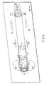
- the pressure of the liquid field model is 2 kPa or less in the vicinity of an edge of the upstream end portion in the three-dimensional model of the treatment portion 26a.
- FIG. 6 illustrates an example of a velocity distribution diagram prepared as a result of the fluid analysis.
- the oscillation direction of the liquid is indicated by arrows D.
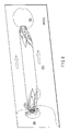
- the velocity of the liquid of the liquid field model converges on one point in a downstream end portion of the three-dimensional model of the treatment portion 26a.
- cavitation generated in an edge portion of the treatment portion 26a when the treatment portion 26a is oscillated toward the tip side is assumed to move from the edge portion of the treatment portion 26a toward the tip side when the treatment portion 26a is oscillated toward the proximal end side.
- cavitation moves from the edge portion of the treatment portion 26a toward the tip side in oscillation of the treatment portion 26a toward the proximal end side.
- Step 3 Change in shape of the three-dimensional model
- the shape of the three-dimensional model of the treatment portion 26a is changed such that the pressures of portions where the pressure is equal to or less than the saturation vapor pressure of the liquid become greater than the saturation vapor pressure.
- the shape of portions of the three-dimensional model in the vicinity of portions of the liquid field model, where the pressure is equal to or less than the saturation vapor pressure of the liquid is changed to a shape having a smaller drag coefficient. If the drag coefficient is small, a pressure gradient becomes gentler, and decrease in the pressure of the liquid in the liquid field model is suppressed. Specifically, in FIG.
- the pressure of the liquid field model in the vicinity of the edge portion of the upstream end portion in the three-dimensional model of the treatment portion 26a is equal to or less than the saturation vapor pressure (2 kPa).
- the shape of the edge portion is changed to a streamline shape having a small drag coefficient.
- the shape of the edge portion of the downstream end is also changed in conformity with the modification of the edge portion of the upstream end.
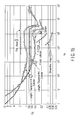
- FIG. 15 illustrates values of drag coefficient C D for Reynolds numbers Re for various shapes.
- Step 4 Repetition of fluid analysis based on the three-dimensional model and change in shape of the three-dimensional model
- Step 5 Determination of final three-dimensional model
- FIG. 7 illustrates an example of the final three-dimensional model of the treatment portion 26a.
- the three-dimensional model of the treatment portion 26a has a shape close to a streamline shape.
- FIG. 8 is a pressure distribution diagram prepared as a result of the fluid analysis of the three-dimensional model of the treatment portion 26a.
- the oscillation direction of the liquid is indicated by arrows D.
- the portions where the pressure is equal to or less than the saturation vapor pressure (2 kPa) have almost been disappeared. Therefore, it is expected that occurrence of cavitation is suppressed in the case where a living tissue is treated in liquid with the treatment portion 26a. Also in a corresponding actual experiment, it has been verified that occurrence of cavitation is suppressed if a living tissue is treated in liquid with the treatment portion 26a.
- the tip portion of the treatment portion 26a is a cavitation suppressing portion 39 that suppresses occurrence of cavitation.
- the ultrasonic coagulation and incision apparatus 16 When a living tissue is treated with the ultrasonic coagulation and incision apparatus 16, the treatment portion 26a and the jaw 30 hold the tissue therebetween, ultrasonic oscillations generated by the ultrasonic oscillator 18 are transmitted to the treatment portion 26a through the probe 24, and then the treatment portion 26a coagulates and incises the held tissue.
- the treatment portion 26a may be immersed in liquid such as humor and blood, the pressure gradient of the liquid is gentle in the vicinity of the external surface of the treatment portion 26a, and thus the pressure of the liquid rarely becomes equal to or less than the saturation vapor pressure of the liquid. Therefore, occurrence of cavitation in the treatment portion 26a is suppressed.
- the ultrasonic coagulation and incision apparatus 16 of the first embodiment has the following effects.
- the treatment portion 26a of the first embodiment is formed to have a shape such that the pressure in the vicinity of the external surface of the treatment portion 26a is greater than the saturation vapor pressure of the liquid, in the fluid analysis concerning the ultrasonic oscillation in the liquid. Further, occurrence of cavitation in the treatment portion 26a when the treatment portion 26a coagulates and incises a living tissue in liquid is actually suppressed, and an optimum cavitation state in coagulation and incision is realized.
- a modification of the first embodiment of the present invention is explained with reference to FIG. 9 .
- an optimum cavitation state is realized for the treatment portion 26a that is oscillated in a three-dimensional manner.
- the treatment portion 26a is oscillated in a one-dimensional manner.
- the treatment portion 26a is oscillated in a three-dimensional manner.
- an amplitude vector of the treatment portion 26a is represented as follows by using vector components in X, Y and Z axis directions.
- A Ax ⁇ i + Ay ⁇ j + Az ⁇ k
- the sizes of amplitudes of the respective axis directions can be calculated by numerical analysis.
- a liquid field model used for fluid analysis in design of the treatment portion 26a is prepared on the basis of the sizes of the amplitudes of the respective axis directions.
- the treatment portion 26a is oscillated in a two-dimensional manner.
- sizes of amplitudes of the X axis and the Y axis are calculated by numerical analysis, and the liquid field model used for the fluid analysis in the method of designing the treatment portion 26a is prepared as indicated by arrow C3.
- FIGS. 10 to 14 illustrate a second embodiment of the present invention. Structures having similar functions as those in the first embodiment are denoted by the same reference numerals as those in the first embodiment, and explanation thereof is omitted.
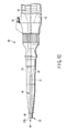
- the ultrasonic treatment apparatus of the second embodiment is an ultrasonic aspiration apparatus 40 that crushes and aspirates a living tissue. As shown in FIG. 10 , an ultrasonic oscillator 18 of the ultrasonic aspiration apparatus 40 is accommodated in a hand piece 42.
- an output end of the ultrasonic oscillator 18 is connected with a proximal end portion of a probe 24, and a treatment portion 26b that emulsifies and crushes a living tissue by transmitted ultrasonic oscillations is formed on a tip portion of the probe 24.
- an aspiration channel 43 to aspirate the crushed tissue is formed through the probe 24 and the ultrasonic oscillator 18 in the longitudinal direction of the probe 24 and the ultrasonic oscillator 18.
- a tip portion of the aspiration channel 43 is opened at the treatment portion 26b and forms an aspiration opening portion 44.
- a proximal end portion of the aspiration channel 43 communicates with an aspiration connecter formed in the hand piece 42, and the aspiration connecter is connected to an aspiration apparatus.
- the probe 24 is covered with a sheath 28, and a clearance between the probe 24 and the sheath 28 forms a liquid conveying channel 46 to convey liquid.
- a tip portion of the liquid conveying channel 46 is annularly opened between the tip portion of the sheath 28 and the probe 24 and forms a liquid conveying opening portion 48.
- a proximal end portion of the liquid conveying channel 46 communicates with a liquid conveying connecter 50 provided on the hand piece, and the liquid conveying connecter 50 is connected with a liquid conveying apparatus.
- the treatment portion 26b of the embodiment has a shape that promotes occurrence of cavitation when the treatment portion 26b is oscillated by ultrasonic waves in liquid such as a physiological saline solution.
- a method of designing the treatment portion 26b is explained below. Explanation of steps similar to those in the designing method according to the first embodiment is omitted.
- Step 1 Preparation of initial three-dimensional model
- a conventional ultrasonic aspiration probe is adopted as an initial three-dimensional model.
- Step 2 Fluid analysis based on the three-dimensional model
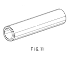
- an almost cylindrical three-dimensional model of the treatment portion 26b is prepared on the basis of a three-dimensional model of the probe 24. Both ends of the three-dimensional model of the treatment portion 26b have the same shape as those of the treatment portion 26b.
- FIG. 12 illustrates an example of a pressure distribution diagram prepared as a result of fluid analysis.
- the oscillation direction of the liquid is indicated by arrows D.
- the pressure of the liquid field model is 2 kPa or less in the vicinity of an annular end surface of a downstream end portion in the three-dimensional model of the treatment portion 26b. Therefore, if a living tissue is actually treated in liquid with the treatment portion 26b, it is expected that cavitation occurs in the vicinity of the annular end surface of the treatment portion 26b when the treatment portion 26b is oscillated toward the rear end side.
- Step 3 Change in shape of the three-dimensional model
- the shape of the three-dimensional model of the treatment portion 26b is changed such that, with respect to portions where cavitation is required to occur when a living tissue is treated in liquid with the treatment portion 26b, the pressure in corresponding portions in the liquid field model is equal to or less than the saturation vapor pressure.
- the shape of the three-dimensional model in the vicinity of portions of the liquid field model where the pressure is required to be equal to or lower than the saturation vapor pressure of the liquid is changed to a shape having a large drag coefficient. Increasing a drag coefficient makes a pressure gradient steep, and increases reduction in pressure of the liquid in the liquid field model.
- the shape of the three-dimensional model is changed such that the both end portions of the external peripheral portions in the three-dimensional model of the treatment portion 26b have the same flange shape to increase the drag coefficient with respect to the oscillation direction of the liquid field.
- Step 4 Repetition of fluid analysis based on the three-dimensional model and the change in shape of the three-dimensional model
- Step 5 Determination of final three-dimensional model
- FIG. 13 illustrates an example of the final three-dimensional model of the treatment portion 26b.
- the three-dimensional model of the treatment portion 26b has a shape in which the end portions have a flange shape.
- FIG. 14 is a pressure distribution diagram prepared as a result of the fluid analysis with respect to the three-dimensional model of the treatment portion 26b.
- the oscillation direction of the liquid is indicated by arrows D.
- portions where the pressure is equal to or less than the saturation vapor pressure (2 kPa) are formed in the vicinity of the annular end surfaces in the both end portions of the three-dimensional model of the treatment portion 26b.
- the tip portion of the treatment portion 26a is a cavitation promoting portion 52 that promotes occurrence of cavitation.
- the ultrasonic aspiration apparatus 40 When a living tissue is treated with the ultrasonic aspiration apparatus 40, an aspiration apparatus and a liquid conveying apparatus are connected to the aspiration connecter and the liquid conveying connecter 50, respectively. Then, the treatment portion 26b and the tissue are immersed in liquid such as physiological saline solution by conveying the liquid through the liquid conveying opening portion 48. In this state, ultrasonic oscillations generated by the ultrasonic oscillator 18 are transmitted to the treatment portion 26b through the probe 24, and the treatment portion 26b is pressed onto the tissue to emulsify and crush the tissue.
- liquid such as physiological saline solution
- the treatment portion 26b is immersed in liquid such as physiological saline solution, the pressure gradient of the liquid is steep in the vicinity of the external surface of the treatment portion 26b, and thus the pressure of the liquid becomes equal to or less than the saturation vapor pressure of the liquid. Therefore, occurrence of cavitation in the treatment portion 26b is promoted. Thus, emulsification and crushing of the tissue are effectively performed.
- the emulsified and crushed tissue is aspirated through the aspiration channel 43 via the aspiration opening portion 44.
- the ultrasonic aspiration apparatus 40 of the second embodiment has the following effects.
- the treatment portion 26b of the second embodiment is formed to have a shape such that the pressure in the vicinity of the external surface of the treatment portion 26b is equal to or less than the saturation vapor pressure of the liquid, in the fluid analysis concerning the ultrasonic oscillation in the liquid. Further, occurrence of cavitation in the treatment portion 26b when the treatment portion 26b emulsifies and crushes a living tissue in liquid is actually promoted, and an optimum cavitation state in emulsification and crushing is realized.
- the treatment portion 26b in the modification has a shape such that occurred cavitation moves toward the tissue when the treatment portion 26b is oscillated by ultrasonic waves in liquid such as physiological saline solution.
- the shape of the three-dimensional model of the treatment portion 26b is changed such that the direction of velocity of the liquid in portions of the liquid field model where the pressure is equal to or less than the saturation vapor pressure of the liquid corresponds to the direction from the treatment portion 26b toward the tissue in treatment on the tissue.
- the shape of the three-dimensional model is changed such that the direction of velocity of the liquid in the portions of the liquid field model, where the pressure is equal to or less than the saturation vapor pressure (2 kPa) of the liquid, in the vicinity of the end portions in the three-dimensional model of the treatment portion 26b corresponds to the direction from the treatment portion 26b toward the tissue in treatment on the tissue, that is, an outward longitudinal direction of the treatment portion 26b.
- cavitation generated by the treatment portion 26b moves toward the tissue, and reaches the tissue to promote emulsification and crushing of the tissue. Therefore, according to the treatment portion 26b of the modification, cavitation generated by the treatment portion 26b efficiently reaches the tissue, and promotes emulsification and crushing of the tissue.
- the present invention provides an ultrasonic treatment apparatus that performs treatment on a living tissue by using ultrasonic waves, such as an ultrasonic coagulation and incision apparatus and an ultrasonic aspiration apparatus, and enables a cavitation state optimal to the treatment of a living tissue.
Landscapes
- Health & Medical Sciences (AREA)
- Life Sciences & Earth Sciences (AREA)
- Surgery (AREA)
- Engineering & Computer Science (AREA)
- Medical Informatics (AREA)
- General Health & Medical Sciences (AREA)
- Biomedical Technology (AREA)
- Heart & Thoracic Surgery (AREA)
- Nuclear Medicine, Radiotherapy & Molecular Imaging (AREA)
- Molecular Biology (AREA)
- Animal Behavior & Ethology (AREA)
- Veterinary Medicine (AREA)
- Public Health (AREA)
- Dentistry (AREA)
- Mechanical Engineering (AREA)
- Otolaryngology (AREA)
- Pathology (AREA)
- Surgical Instruments (AREA)
Abstract
Description
- This invention relates to an ultrasonic treatment apparatus that performs treatment on a living tissue by using ultrasonic waves, such as an ultrasonic coagulation and incision apparatus and an ultrasonic aspiration apparatus.
- In prior art, ultrasonic treatment apparatuses that perform treatment on a living tissue by using ultrasonic waves have been used. For example, Jpn. Pat. Appln. KOKAI Pub.
No. 2004-321606 No. 2004-321606 - If a living tissue is treated in the state where the treatment portion is immersed in liquid such as humor and blood, the tissue may be damaged due to cavitation occurring on the treatment portion.
USP 6,790,216 discloses an ultrasonic coagulation and incision apparatus that suppresses occurrence of cavitation on a treatment portion. The ultrasonic coagulation and incision apparatus ofUSP 6,790,216 has almost the same structure as that of the ultrasonic coagulation and incision apparatus of Jpn. Pat. Appln. KOKAI Pub.No. 2004-321606 USP 6,790,216 also discloses that reducing the inclination angle of the inclined portion suppresses cavitation occurring in the treatment portion. - On the other hand, Jpn. Pat. Appln. KOKAI Pub.
No. 2002-233533 No. 2002-233533 No. 2004-321606 USP 6,790,216 . Further, a treatment portion that emulsifies and crushes a living tissue is formed on a tip portion of the probe of the ultrasonic aspiration apparatus disclosed in Jpn. Pat. Appln. KOKAI Pub.No. 2002-233533 - As described above, when a living tissue is coagulated and incised, the cavitation in the treatment portion should desirably be suppressed so as to prevent damage to the living tissue. On the other hand, when a living tissue is crushed and aspirated, the cavitation should desirably be promoted so as to effectively crush the living tissue.
-
USP 6,790,216 discloses suppressing the cavitation by reducing the inclination angle of an inclined portion that faces the holding surface of a treatment portion. However,USP 6,790,216 does not produce a cavitation state that is optimal to the treatment of a living tissue. - The present invention has been made in consideration of the above problems, and is intended to provide an ultrasonic treatment apparatus that enables a cavitation state optimal to the treatment of a living tissue.
- In an aspect of the present invention, an ultrasonic treatment apparatus is characterized by comprising: an ultrasonic oscillator which generates ultrasonic waves; a probe which is connected to the ultrasonic oscillator, and transmits ultrasonic oscillations generated by the ultrasonic oscillator; a treatment portion which is formed on the probe, and treats a living tissue by the transmitted ultrasonic oscillations, and in that the treatment portion includes a cavitation suppressing portion formed to have a such shape that a pressure of a liquid in a vicinity of an external surface of the cavitation suppressing portion is greater than a saturation vapor pressure of the liquid in fluid analysis concerning ultrasonic oscillations in the liquid.
- This ultrasonic treatment apparatus is featured in that when the treatment portion treats a living tissue in a liquid, the pressure of the liquid located in the vicinity of the external surface of the cavitation suppressing portion becomes greater than the saturation vapor pressure of the liquid. Accordingly, the cavitation in the treatment portion is suppressed.
- In a preferred aspect of the present invention, an ultrasonic treatment apparatus is characterized in that the cavitation suppressing portion is formed to have a shape having a small drag coefficient.
- This ultrasonic treatment apparatus is featured in that when the treatment portion treats a living tissue in a liquid, the pressure of the liquid located in the vicinity of the external surface of the cavitation suppressing portion changes with a gentle slope and tends to be greater than the saturation vapor pressure of the liquid.
- In a preferred aspect of the present invention, an ultrasonic treatment apparatus is characterized by used to coagulate and incise the living tissue.
- This ultrasonic treatment apparatus is featured in that the treatment portion performs coagulation and incision in the state where the cavitation is suppressed in the treatment portion.
- In a preferred aspect of the present invention, an ultrasonic treatment apparatus is characterized by further comprising: a jaw which is opened and closed with respect to the treatment portion, and holds the tissue in cooperation with the treatment portion.
- This ultrasonic treatment apparatus is featured in that a living tissue is treated by the treatment portion in the state where it is held by the treatment portion and jaw.
- In another aspect of the present invention, an ultrasonic treatment apparatus characterized by comprising: an ultrasonic oscillator which generates ultrasonic waves; a probe which is connected to the ultrasonic oscillator, and transmits ultrasonic oscillations generated by the ultrasonic oscillator; and a treatment portion which is formed on the probe, and treats a living tissue by the transmitted ultrasonic oscillations, and in that the treatment portion includes a cavitation promoting portion formed to have such a shape that a pressure of a liquid in a vicinity of an external surface of the cavitation promoting portion is equal to or less than a saturation vapor pressure of the liquid in fluid analysis concerning ultrasonic oscillations in the liquid.
- This ultrasonic treatment apparatus is featured in that when the treatment portion treats a living tissue in a liquid, the pressure of the liquid located in the vicinity of the external surface of the cavitation promoting portion becomes equal to or less than the saturation vapor pressure of the liquid. Accordingly, the cavitation in the treatment portion is promoted.
- In a preferred aspect of the present invention, an ultrasonic treatment apparatus is characterized in that the cavitation promoting portion is formed to have a shape having a large drag coefficient.
- This ultrasonic treatment apparatus is featured in that when the treatment portion treats a living tissue in a liquid, the pressure of the liquid located in the vicinity of the external surface of the cavitation suppressing portion changes with a steep slope and tends to be equal to or less than the saturation vapor pressure of the liquid.
- In a preferred aspect of the present invention, an ultrasonic treatment apparatus is characterized by used to crush and aspirate the living tissue and further comprising: an aspiration channel which aspirates the crushed living tissue.
- This ultrasonic treatment apparatus is featured in that the treatment portion crushes a living tissue in the state where the cavitation is promoted in the treatment portion, and the crushed living tissue is aspirated into the aspiration channel.
- In a preferred aspect of the present invention, an ultrasonic treatment apparatus is characterized in that the treatment portion is formed to have a shape such that a direction of a velocity of the liquid in the vicinity of the external surface of the cavitation promoting portion corresponds to a direction from the treatment portion toward the tissue in treatment on the tissue in the fluid analysis concerning the ultrasonic oscillations in the liquid.
- The ultrasonic treatment apparatus is featured in that when the treatment portion treats a living tissue in a liquid, the cavitation occurring in the vicinity of the external surface of the cavitation promoting portion moves toward the living tissue.
- In another aspect of the present invention, a probe for an ultrasonic treatment apparatus is used in the above ultrasonic treatment apparatus.
- In another aspect of the present invention, a method of manufacturing a probe for an ultrasonic treatment apparatus is characterized by comprising: preparing a predetermined shape model for at least part of a treatment portion which treats a living tissue by ultrasonic oscillations; obtaining, by fluid analysis concerning ultrasonic oscillations in a liquid, a pressure distribution of the liquid with respect to the shape model; changing a shape of the shape model such that a pressure of at least part of portions where the pressure is equal to or less than a saturation vapor pressure of the liquid in the pressure distribution becomes greater than the saturation vapor pressure of the liquid; alternately repeating the obtaining the pressure distribution of the liquid and the changing the shape of the shape model; and forming the treatment portion to have a shape of the shape model.
- In a preferred aspect of the present invention, a method of manufacturing a probe for an ultrasonic treatment apparatus is characterized in that the changing the shape of the shape model includes changing the shape of the shape model such that a drag coefficient is reduced.
- In another aspect of the present invention, a method of manufacturing a probe for an ultrasonic treatment apparatus is characterized by comprising: preparing a predetermined shape model for at least part of a treatment portion which treats a living tissue by ultrasonic oscillations; obtaining, by fluid analysis concerning ultrasonic oscillations in a liquid, a pressure distribution of the liquid with respect to the shape model; changing a shape of the shape model such that a pressure of at least part of portions where the pressure is greater than a saturation vapor pressure of the liquid in the pressure distribution becomes less than the saturation vapor pressure of the liquid; alternately repeating the obtaining the pressure distribution of the liquid and the changing the shape of the shape model; and forming the treatment portion to have a shape of the shape model.
- In a preferred aspect of the present invention, a method of manufacturing a probe for an ultrasonic treatment apparatus is characterized in that the changing the shape of the shape model includes changing the shape of the shape model such that a drag coefficient is increased.
- In a preferred aspect of the present invention, a method of manufacturing a probe for an ultrasonic treatment apparatus is characterized by further comprising: changing the shape of the shape model such that a direction of a velocity of the liquid in at least part of portions where the pressure is less than the saturation vapor pressure of the liquid in the pressure distribution corresponds to a direction from the treatment portion toward the tissue in treatment on the tissue.
- In another aspect of the present invention, a method of manufacturing an ultrasonic treatment apparatus is characterized by comprising the above method of manufacturing a probe for an ultrasonic treatment apparatus.
- The ultrasonic treatment apparatus according to the present invention enables a cavitation state that is optimal to the treatment of a living tissue.
- In addition, the method of manufacturing a probe for use in an ultrasonic treatment apparatus, according to the present invention, enables the manufacture of an ultrasonic treatment apparatus capable of producing a cavitation state that is optimal to the treatment of a living tissue.
-
-
FIG. 1 is a side view of an ultrasonic coagulation and incision apparatus according to a first embodiment of the present invention. -
FIG. 2 is a perspective view of a tip portion of the ultrasonic coagulation and incision apparatus according to the first embodiment of the present invention. -
FIG. 3A is a perspective view of a probe of the ultrasonic coagulation and incision apparatus according to the first embodiment of the present invention, in an oscillation state toward a tip side. -
FIG. 3B is a perspective view of the probe of the ultrasonic coagulation and incision apparatus according to the first embodiment of the present invention, in an oscillation state toward a rear end side. -
FIG. 4 is a perspective view of an initial three-dimensional model of a treatment portion, in a method of designing the treatment portion of the ultrasonic coagulation and incision apparatus according to the first embodiment of the present invention. -
FIG. 5 is a pressure distribution diagram for the initial three-dimensional model prepared as a result of fluid analysis, in the method of designing the treatment portion of the ultrasonic coagulation and incision apparatus according to the first embodiment of the present invention. -
FIG. 6 is a velocity distribution diagram for the initial three-dimensional model prepared as a result of fluid analysis, in the method of designing the treatment portion of the ultrasonic coagulation and incision apparatus according to the first embodiment of the present invention. -
FIG. 7 is a perspective view of a final three-dimensional model of the treatment portion, in the method of designing the treatment portion of the ultrasonic coagulation and incision apparatus according to the first embodiment of the present invention. -
FIG. 8 is a pressure distribution diagram of the final three-dimensional model prepared as a result of fluid analysis, in the method of designing the treatment portion of the ultrasonic coagulation and incision apparatus according to the first embodiment of the present invention. -
FIG. 9 is a perspective view of a probe of an ultrasonic coagulation and incision apparatus according to a modification of the first embodiment of the present invention, in an oscillation state. -
FIG. 10 is a side view of an ultrasonic aspiration apparatus according to a second embodiment of the present invention. -
FIG. 11 is a perspective view of an initial three-dimensional model of a treatment portion, in a method of designing the treatment portion of the ultrasonic coagulation and incision apparatus according to the second embodiment of the present invention. -
FIG. 12 is a pressure distribution diagram for the initial three-dimensional model prepared as a result of fluid analysis, in the method of designing the treatment portion of the ultrasonic coagulation and incision apparatus according to the second embodiment of the present invention. -
FIG. 13 is a perspective view of a final three-dimensional model of the treatment portion, in the method of designing the treatment portion of the ultrasonic coagulation and incision apparatus according to the second embodiment of the present invention. -
FIG. 14 is a pressure distribution diagram for the initial three-dimensional model prepared as a result of fluid analysis, in the method of designing the treatment portion of the ultrasonic coagulation and incision apparatus according to the second embodiment of the present invention. -
FIG. 15 is a diagram illustrating values of a drag coefficient CD with respect to Reynolds numbers Re for various forms. - A first embodiment of the present invention is described with reference to
FIGS. 1 to 8 . The ultrasonic treatment apparatus according to the first embodiment is an ultrasonic coagulation andincision apparatus 16 that suppresses occurrence of cavitation. As shown inFIG. 1 , the ultrasonic coagulation andincision apparatus 16 has anultrasonic oscillator 18 that generates ultrasonic oscillations. Theultrasonic oscillator 18 is accommodated in acylindrical cover 20. Acode 22 to supply electric power to theultrasonic oscillator 18 is extended out of a proximal end portion of thecylindrical cover 20. Further, an output end on a tip portion of theultrasonic oscillator 18 is connected with a proximal end portion of aprobe 24 transmitting the ultrasonic oscillations and having an elongated straight shape. Atreatment portion 26a that coagulates and incises a living tissue by the transmitted ultrasonic oscillations is formed on a tip portion of theprobe 24. - Further, the
probe 24 is covered with asheath 28. Ajaw 30 that is opened and closed with respect to thetreatment portion 26a and holds a living tissue in cooperation with thetreatment portion 26a is provided on a tip portion of thesheath 28. On the other hand, a proximal end portion of thesheath 28 is connected with an operationmain body 32 such that thesheath 28 is rotatable around its central axis. Arotary knob 34 to rotate thesheath 28 is provided on the proximal end portion of thesheath 28. Further, a fixedhandle 36 and amovable handle 38 to open and close thejaw 30 are provided on the operationmain body 32. Specifically, themovable handle 38 is pivotally supported by the operationmain body 32 such that themovable handle 38 is openable and closable with respect to the fixedhandle 36, and is pivotally supported by a proximal end portion of an operation rod located in the operationmain body 32. The operation rod is inserted through the operationmain body 32 and thesheath 28 such that the operation rod is movable back and forth, and the tip portion of the operation rod is connected to a proximal end of thejaw 30. Further, the operation rod is moved back and forth by opening and closing themovable handle 38 with respect to the fixedhandle 36, and thereby thejaw 30 is opened and closed with respect to thetreatment portion 26a. - The
treatment portion 26a illustrated inFIG. 2 according to the first embodiment has a form that suppresses generation of cavitation in the case where it is oscillated by ultrasonic waves in liquid such as humor and blood. The following is explanation of a method of designing thetreatment portion 26a. - An initial three-dimensional model is prepared for the
probe 24 as shown inFIGS. 3A and3B . In the first embodiment, a conventional ultrasonic coagulation and incision probe is adopted as the initial three-dimensional model. - Fluid analysis is performed for the case where the
probe 24 is oscillated in liquid by ultrasonic waves. - The
probe 24 is longitudinally oscillated in liquid in its longitudinal direction with a predetermined amplitude and period. Specifically, theprobe 24 repeats oscillation toward the tip side illustrated by arrow B1 inFIG. 3A , and oscillation toward the proximal end side shown by arrow B2 inFIG. 3B . In the first embodiment, analysis is performed by using a coordinate system fixed on theprobe 24. In the coordinate system, theprobe 24 is located in a state of rest in a liquid field that oscillates with a predetermined amplitude and period, such that the longitudinal direction of theprobe 24 coincides with the oscillation direction of the liquid. Specifically, the liquid repeats oscillation toward the proximal end side illustrated by arrow C1 inFIG. 3A , and oscillation toward the tip side illustrated by arrow C2 inFIG. 3B . - In the first embodiment, fluid analysis is performed only with respect to the
treatment portion 26a in the tip portion of theprobe 24, to reduce analysis time in the fluid analysis. Specifically, a three-dimensional model of thetreatment portion 26a whose both end portions have the same shape as those of thetreatment portion 26a is prepared on the basis of the three-dimensional model of theprobe 24.FIG. 4 illustrates an example of the prepared three-dimensional model of thetreatment portion 26a. The three-dimensional model of thetreatment portion 26a corresponds to a cylindrical shape adopted in thetreatment portion 26a of a conventional ultrasonic coagulation andincision probe 24. - Then, prepared is a liquid field model for a half period of the above liquid field that oscillates in the one direction with a predetermined amplitude and period, that is, a liquid field model whose amplitude increases from 0 to its maximum amplitude and decreases from the maximum amplitude to 0 with a predetermined period, and then amplitude increases again without decrease. The three-dimensional model of the
treatment portion 26a is located in a state of rest in the liquid field model such that the longitudinal direction of the three-dimensional model coincides with the oscillation direction of the liquid, and then fluid analysis is performed. In the three-dimensional model of thetreatment portion 26a, at an end portion on an upstream side of the oscillation direction of the liquid field model, behavior when thetreatment portion 26a is oscillated toward the tip side is analyzed. At an end portion on a downstream side of the oscillation direction, behavior when thetreatment portion 26a is oscillated toward the proximal end side is analyzed. In fluid analysis, a pressure distribution and a velocity distribution of the liquid field model are calculated. - Based on the pressure distribution of the liquid field model, occurrence of cavitation is analyzed. Generally, cavitation occurs if the liquid reaches its saturation vapor pressure. For example, water reaches its saturation vapor pressure and cavitation occurs, when its temperature is increased to 100°C under atmospheric pressure (101.3 kPa), and when its pressure is reduced to 2 kPa under standard temperature (20°C). If a living tissue is treated in liquid with the
treatment portion 26a, it is expected that cavitation occurs in portions corresponding to portions of the liquid, whose pressures are reduced to its saturation vapor pressure in the liquid field model. -
FIG. 5 illustrates an example of a pressure distribution diagram prepared as a result of the fluid analysis. InFIG. 5 , the oscillation direction of the liquid is indicated by arrows D. Water at standard temperature (20°C) is selected as the liquid of the liquid field model. It is expected that cavitation occurs in portions where the pressure is equal to or less than the saturation vapor pressure (2 kPa) in the liquid field model. As shown inFIG. 5 , the pressure of the liquid field model is 2 kPa or less in the vicinity of an edge of the upstream end portion in the three-dimensional model of thetreatment portion 26a. Thus, if a living tissue is treated in liquid with thetreatment portion 26a, it is expected that cavitation occurs in the vicinity of an edge portion of thetreatment portion 26a when thetreatment portion 26a is oscillated toward the tip side. In a corresponding actual experiment, it has been verified that cavitation occurs in an edge portion of thetreatment portion 26a when it is oscillated toward the tip side if a living tissue is treated in liquid with thetreatment portion 26a. -
FIG. 6 illustrates an example of a velocity distribution diagram prepared as a result of the fluid analysis. InFIG. 6 , the oscillation direction of the liquid is indicated by arrows D. As shown inFIG. 6 , it is understood that the velocity of the liquid of the liquid field model converges on one point in a downstream end portion of the three-dimensional model of thetreatment portion 26a. Specifically, cavitation generated in an edge portion of thetreatment portion 26a when thetreatment portion 26a is oscillated toward the tip side is assumed to move from the edge portion of thetreatment portion 26a toward the tip side when thetreatment portion 26a is oscillated toward the proximal end side. Also in a corresponding actual experiment, it has been verified that cavitation moves from the edge portion of thetreatment portion 26a toward the tip side in oscillation of thetreatment portion 26a toward the proximal end side. - The shape of the three-dimensional model of the
treatment portion 26a is changed such that the pressures of portions where the pressure is equal to or less than the saturation vapor pressure of the liquid become greater than the saturation vapor pressure. In the first embodiment, the shape of portions of the three-dimensional model in the vicinity of portions of the liquid field model, where the pressure is equal to or less than the saturation vapor pressure of the liquid, is changed to a shape having a smaller drag coefficient. If the drag coefficient is small, a pressure gradient becomes gentler, and decrease in the pressure of the liquid in the liquid field model is suppressed. Specifically, inFIG. 5 , the pressure of the liquid field model in the vicinity of the edge portion of the upstream end portion in the three-dimensional model of thetreatment portion 26a is equal to or less than the saturation vapor pressure (2 kPa). The shape of the edge portion is changed to a streamline shape having a small drag coefficient. As a matter of course, the shape of the edge portion of the downstream end is also changed in conformity with the modification of the edge portion of the upstream end.FIG. 15 illustrates values of drag coefficient CD for Reynolds numbers Re for various shapes. - The fluid analysis based on the three-dimensional model of
Step 2 and the change in shape of the three-dimensional model ofStep 3 are alternately repeated. - When the portions in the liquid field model where the pressure is reduced to the saturation vapor pressure of the liquid are almost disappeared, change in shape of the three-dimensional model is ended, and the final three-dimensional model of the
treatment portion 26a is determined. -
FIG. 7 illustrates an example of the final three-dimensional model of thetreatment portion 26a. As shown inFIG. 7 , the three-dimensional model of thetreatment portion 26a has a shape close to a streamline shape.FIG. 8 is a pressure distribution diagram prepared as a result of the fluid analysis of the three-dimensional model of thetreatment portion 26a. InFIG. 8 , the oscillation direction of the liquid is indicated by arrows D. As shown inFIG. 8 , the portions where the pressure is equal to or less than the saturation vapor pressure (2 kPa) have almost been disappeared. Therefore, it is expected that occurrence of cavitation is suppressed in the case where a living tissue is treated in liquid with thetreatment portion 26a. Also in a corresponding actual experiment, it has been verified that occurrence of cavitation is suppressed if a living tissue is treated in liquid with thetreatment portion 26a. - As described above, according to the first embodiment, the tip portion of the
treatment portion 26a is acavitation suppressing portion 39 that suppresses occurrence of cavitation. - Next, operation of the ultrasonic coagulation and
incision apparatus 16 according to the first embodiment is explained. When a living tissue is treated with the ultrasonic coagulation andincision apparatus 16, thetreatment portion 26a and thejaw 30 hold the tissue therebetween, ultrasonic oscillations generated by theultrasonic oscillator 18 are transmitted to thetreatment portion 26a through theprobe 24, and then thetreatment portion 26a coagulates and incises the held tissue. In this process, although thetreatment portion 26a may be immersed in liquid such as humor and blood, the pressure gradient of the liquid is gentle in the vicinity of the external surface of thetreatment portion 26a, and thus the pressure of the liquid rarely becomes equal to or less than the saturation vapor pressure of the liquid. Therefore, occurrence of cavitation in thetreatment portion 26a is suppressed. - Therefore, the ultrasonic coagulation and
incision apparatus 16 of the first embodiment has the following effects. Thetreatment portion 26a of the first embodiment is formed to have a shape such that the pressure in the vicinity of the external surface of thetreatment portion 26a is greater than the saturation vapor pressure of the liquid, in the fluid analysis concerning the ultrasonic oscillation in the liquid. Further, occurrence of cavitation in thetreatment portion 26a when thetreatment portion 26a coagulates and incises a living tissue in liquid is actually suppressed, and an optimum cavitation state in coagulation and incision is realized. - A modification of the first embodiment of the present invention is explained with reference to
FIG. 9 . In the modification, an optimum cavitation state is realized for thetreatment portion 26a that is oscillated in a three-dimensional manner. - In the
probe 24 having a straight shape as in the first embodiment, thetreatment portion 26a is oscillated in a one-dimensional manner. On the other hand, in acommon probe 24, thetreatment portion 26a is oscillated in a three-dimensional manner. Specifically, an amplitude vector of thetreatment portion 26a is represented as follows by using vector components in X, Y and Z axis directions.
- i, j, k: unit vectors of respective axis directions
- Ax, Ay, Az: sizes of amplitudes of respective axis directions
- The sizes of amplitudes of the respective axis directions can be calculated by numerical analysis. A liquid field model used for fluid analysis in design of the
treatment portion 26a is prepared on the basis of the sizes of the amplitudes of the respective axis directions. - For example, in the
probe 24 having a curved shape as shown inFIG. 9 , thetreatment portion 26a is oscillated in a two-dimensional manner. In this case, sizes of amplitudes of the X axis and the Y axis are calculated by numerical analysis, and the liquid field model used for the fluid analysis in the method of designing thetreatment portion 26a is prepared as indicated by arrow C3. -
FIGS. 10 to 14 illustrate a second embodiment of the present invention. Structures having similar functions as those in the first embodiment are denoted by the same reference numerals as those in the first embodiment, and explanation thereof is omitted. The ultrasonic treatment apparatus of the second embodiment is an ultrasonic aspiration apparatus 40 that crushes and aspirates a living tissue. As shown inFIG. 10 , anultrasonic oscillator 18 of the ultrasonic aspiration apparatus 40 is accommodated in ahand piece 42. Further, an output end of theultrasonic oscillator 18 is connected with a proximal end portion of aprobe 24, and atreatment portion 26b that emulsifies and crushes a living tissue by transmitted ultrasonic oscillations is formed on a tip portion of theprobe 24. - Further, an aspiration channel 43 to aspirate the crushed tissue is formed through the
probe 24 and theultrasonic oscillator 18 in the longitudinal direction of theprobe 24 and theultrasonic oscillator 18. A tip portion of the aspiration channel 43 is opened at thetreatment portion 26b and forms anaspiration opening portion 44. A proximal end portion of the aspiration channel 43 communicates with an aspiration connecter formed in thehand piece 42, and the aspiration connecter is connected to an aspiration apparatus. - Further, the
probe 24 is covered with asheath 28, and a clearance between theprobe 24 and thesheath 28 forms aliquid conveying channel 46 to convey liquid. A tip portion of theliquid conveying channel 46 is annularly opened between the tip portion of thesheath 28 and theprobe 24 and forms a liquid conveyingopening portion 48. A proximal end portion of theliquid conveying channel 46 communicates with aliquid conveying connecter 50 provided on the hand piece, and theliquid conveying connecter 50 is connected with a liquid conveying apparatus. - The
treatment portion 26b of the embodiment has a shape that promotes occurrence of cavitation when thetreatment portion 26b is oscillated by ultrasonic waves in liquid such as a physiological saline solution. A method of designing thetreatment portion 26b is explained below. Explanation of steps similar to those in the designing method according to the first embodiment is omitted. - In the second embodiment, a conventional ultrasonic aspiration probe is adopted as an initial three-dimensional model.
- As shown in
FIG. 11 , an almost cylindrical three-dimensional model of thetreatment portion 26b is prepared on the basis of a three-dimensional model of theprobe 24. Both ends of the three-dimensional model of thetreatment portion 26b have the same shape as those of thetreatment portion 26b. -
FIG. 12 illustrates an example of a pressure distribution diagram prepared as a result of fluid analysis. InFIG. 12 , the oscillation direction of the liquid is indicated by arrows D. As shown inFIG. 12 , the pressure of the liquid field model is 2 kPa or less in the vicinity of an annular end surface of a downstream end portion in the three-dimensional model of thetreatment portion 26b. Therefore, if a living tissue is actually treated in liquid with thetreatment portion 26b, it is expected that cavitation occurs in the vicinity of the annular end surface of thetreatment portion 26b when thetreatment portion 26b is oscillated toward the rear end side. - The shape of the three-dimensional model of the
treatment portion 26b is changed such that, with respect to portions where cavitation is required to occur when a living tissue is treated in liquid with thetreatment portion 26b, the pressure in corresponding portions in the liquid field model is equal to or less than the saturation vapor pressure. In the second embodiment, the shape of the three-dimensional model in the vicinity of portions of the liquid field model where the pressure is required to be equal to or lower than the saturation vapor pressure of the liquid is changed to a shape having a large drag coefficient. Increasing a drag coefficient makes a pressure gradient steep, and increases reduction in pressure of the liquid in the liquid field model. Specifically, with reference toFIG. 12 , if the pressure of the portions of the liquid field model in the vicinity of the annular end surfaces in the both end portions of the three-dimensional model of thetreatment portion 26b is required to be equal to or lower than the saturation vapor pressure (2 kPa), the shape of the three-dimensional model is changed such that the both end portions of the external peripheral portions in the three-dimensional model of thetreatment portion 26b have the same flange shape to increase the drag coefficient with respect to the oscillation direction of the liquid field. - When the pressure in the portions in the liquid field model, which is required to be equal to or less than the saturation vapor pressure, has become equal to or less than the saturation vapor pressure, change in shape of the three-dimensional model is ended, and a final three-dimensional model of the
treatment portion 26b is determined. -
FIG. 13 illustrates an example of the final three-dimensional model of thetreatment portion 26b. As shown inFIG. 13 , the three-dimensional model of thetreatment portion 26b has a shape in which the end portions have a flange shape.FIG. 14 is a pressure distribution diagram prepared as a result of the fluid analysis with respect to the three-dimensional model of thetreatment portion 26b. InFIG. 14 , the oscillation direction of the liquid is indicated by arrows D. As shown inFIG. 14 , portions where the pressure is equal to or less than the saturation vapor pressure (2 kPa) are formed in the vicinity of the annular end surfaces in the both end portions of the three-dimensional model of thetreatment portion 26b. Therefore, it is expected that occurrence of cavitation is promoted in the case where a living tissue is treated in liquid with thetreatment portion 26b. Also in a corresponding actual experiment, it has been verified that occurrence of cavitation is promoted if a living tissue is treated in liquid with thetreatment portion 26b. - As described above, according to the second embodiment, the tip portion of the
treatment portion 26a is acavitation promoting portion 52 that promotes occurrence of cavitation. - Next, operation of the ultrasonic aspiration apparatus 40 according to the second embodiment is explained. When a living tissue is treated with the ultrasonic aspiration apparatus 40, an aspiration apparatus and a liquid conveying apparatus are connected to the aspiration connecter and the
liquid conveying connecter 50, respectively. Then, thetreatment portion 26b and the tissue are immersed in liquid such as physiological saline solution by conveying the liquid through the liquid conveyingopening portion 48. In this state, ultrasonic oscillations generated by theultrasonic oscillator 18 are transmitted to thetreatment portion 26b through theprobe 24, and thetreatment portion 26b is pressed onto the tissue to emulsify and crush the tissue. In this process, thetreatment portion 26b is immersed in liquid such as physiological saline solution, the pressure gradient of the liquid is steep in the vicinity of the external surface of thetreatment portion 26b, and thus the pressure of the liquid becomes equal to or less than the saturation vapor pressure of the liquid. Therefore, occurrence of cavitation in thetreatment portion 26b is promoted. Thus, emulsification and crushing of the tissue are effectively performed. The emulsified and crushed tissue is aspirated through the aspiration channel 43 via theaspiration opening portion 44. - Therefore, the ultrasonic aspiration apparatus 40 of the second embodiment has the following effects. The
treatment portion 26b of the second embodiment is formed to have a shape such that the pressure in the vicinity of the external surface of thetreatment portion 26b is equal to or less than the saturation vapor pressure of the liquid, in the fluid analysis concerning the ultrasonic oscillation in the liquid. Further, occurrence of cavitation in thetreatment portion 26b when thetreatment portion 26b emulsifies and crushes a living tissue in liquid is actually promoted, and an optimum cavitation state in emulsification and crushing is realized. - The following is explanation of a modification of the second embodiment of the present invention. The
treatment portion 26b in the modification has a shape such that occurred cavitation moves toward the tissue when thetreatment portion 26b is oscillated by ultrasonic waves in liquid such as physiological saline solution. - In a method of designing the
treatment portion 26b of the modification, in a step of changing the shape of the three-dimensional model, the shape of the three-dimensional model of thetreatment portion 26b is changed such that the direction of velocity of the liquid in portions of the liquid field model where the pressure is equal to or less than the saturation vapor pressure of the liquid corresponds to the direction from thetreatment portion 26b toward the tissue in treatment on the tissue. Specifically, with reference toFIG. 14 , the shape of the three-dimensional model is changed such that the direction of velocity of the liquid in the portions of the liquid field model, where the pressure is equal to or less than the saturation vapor pressure (2 kPa) of the liquid, in the vicinity of the end portions in the three-dimensional model of thetreatment portion 26b corresponds to the direction from thetreatment portion 26b toward the tissue in treatment on the tissue, that is, an outward longitudinal direction of thetreatment portion 26b. - When a living tissue is treated with the ultrasonic aspiration apparatus 40 according to the modification, cavitation generated by the
treatment portion 26b moves toward the tissue, and reaches the tissue to promote emulsification and crushing of the tissue. Therefore, according to thetreatment portion 26b of the modification, cavitation generated by thetreatment portion 26b efficiently reaches the tissue, and promotes emulsification and crushing of the tissue. - The present invention provides an ultrasonic treatment apparatus that performs treatment on a living tissue by using ultrasonic waves, such as an ultrasonic coagulation and incision apparatus and an ultrasonic aspiration apparatus, and enables a cavitation state optimal to the treatment of a living tissue.
Claims (15)
- An ultrasonic treatment apparatus characterized by comprising:an ultrasonic oscillator (18) which generates ultrasonic waves;a probe (24) which is connected to the ultrasonic oscillator (18), and transmits ultrasonic oscillations generated by the ultrasonic oscillator (18);a treatment portion (26a) which is formed on the probe (24), and treats a living tissue by the transmitted ultrasonic oscillations, and in thatthe treatment portion (26a) includes a cavitation suppressing portion (39) formed to have a such shape that a pressure of a liquid in a vicinity of an external surface of the cavitation suppressing portion (39) is greater than a saturation vapor pressure of the liquid in fluid analysis concerning ultrasonic oscillations in the liquid.
- An ultrasonic treatment apparatus according to claim 1, characterized in that
the cavitation suppressing portion (39) is formed to have a shape having a small drag coefficient. - An ultrasonic treatment apparatus according to claim 1 or 2, characterized by used to coagulate and incise the living tissue.
- An ultrasonic treatment apparatus according to claim 3, characterized by further comprising:a jaw (30) which is opened and closed with respect to the treatment portion (26a), and holds the tissue in cooperation with the treatment portion (26a).
- An ultrasonic treatment apparatus characterized by comprising:an ultrasonic oscillator (18) which generates ultrasonic waves;a probe (24) which is connected to the ultrasonic oscillator (18), and transmits ultrasonic oscillations generated by the ultrasonic oscillator (18); anda treatment portion (26a) which is formed on the probe (24), and treats a living tissue by the transmitted ultrasonic oscillations, and in thatthe treatment portion (26a) includes a cavitation promoting portion (52) formed to have such a shape that a pressure of a liquid in a vicinity of an external surface of the cavitation promoting portion (52) is equal to or less than a saturation vapor pressure of the liquid in fluid analysis concerning ultrasonic oscillations in the liquid.
- An ultrasonic treatment apparatus according to claim 5, characterized in that
the cavitation promoting portion (52) is formed to have a shape having a large drag coefficient. - An ultrasonic treatment apparatus according to claim 5 or 6, characterized by used to crush and aspirate the living tissue and further comprising:an aspiration channel (43) which aspirates the crushed living tissue.
- An ultrasonic treatment apparatus according to claim 5 or 6, characterized in that the treatment portion (26a) is formed to have a shape such that a direction of a velocity of the liquid in the vicinity of the external surface of the cavitation promoting portion (52) corresponds to a direction from the treatment portion (26a) toward the tissue in treatment on the tissue in the fluid analysis concerning the ultrasonic oscillations in the liquid.
- A probe for an ultrasonic treatment apparatus used in the ultrasonic treatment apparatus according to any one of claims 1 to 8.
- A method of manufacturing a probe for an ultrasonic treatment apparatus, characterized by comprising:preparing a predetermined shape model for at least part of a treatment portion which treats a living tissue by ultrasonic oscillations;obtaining, by fluid analysis concerning ultrasonic oscillations in a liquid, a pressure distribution of the liquid with respect to the shape model;changing a shape of the shape model such that a pressure of at least part of portions where the pressure is equal to or less than a saturation vapor pressure of the liquid in the pressure distribution becomes greater than the saturation vapor pressure of the liquid;alternately repeating the obtaining the pressure distribution of the liquid and the changing the shape of the shape model; andforming the treatment portion to have a shape of the shape model.
- A method of manufacturing a probe for an ultrasonic treatment apparatus according to claim 10, characterized in that
the changing the shape of the shape model includes changing the shape of the shape model such that a drag coefficient is reduced. - A method of manufacturing a probe for an ultrasonic treatment apparatus, characterized by comprising:preparing a predetermined shape model for at least part of a treatment portion which treats a living tissue by ultrasonic oscillations;obtaining, by fluid analysis concerning ultrasonic oscillations in a liquid, a pressure distribution of the liquid with respect to the shape model;changing a shape of the shape model such that a pressure of at least part of portions where the pressure is greater than a saturation vapor pressure of the liquid in the pressure distribution becomes less than the saturation vapor pressure of the liquid;alternately repeating the obtaining the pressure distribution of the liquid and the changing the shape of the shape model; andforming the treatment portion to have a shape of the shape model.
- A method of manufacturing a probe for an ultrasonic treatment apparatus according to claim 12, characterized in that
the changing the shape of the shape model includes changing the shape of the shape model such that a drag coefficient is increased. - A method of manufacturing a probe for an ultrasonic treatment apparatus according to claim 12 or 13, characterized by further comprising:changing the shape of the shape model such that a direction of a velocity of the liquid in at least part of portions where the pressure is less than the saturation vapor pressure of the liquid in the pressure distribution corresponds to a direction from the treatment portion (26a) toward the tissue in treatment on the tissue.
- A method of manufacturing an ultrasonic treatment apparatus, characterized by comprising the method of manufacturing a probe for an ultrasonic treatment apparatus according to any one of claim 10 to 14.
Applications Claiming Priority (2)
| Application Number | Priority Date | Filing Date | Title |
|---|---|---|---|
| JP2005176554A JP4398408B2 (en) | 2005-06-16 | 2005-06-16 | Ultrasonic treatment apparatus, probe for ultrasonic treatment apparatus, and manufacturing method thereof |
| PCT/JP2006/310127 WO2006134751A1 (en) | 2005-06-16 | 2006-05-22 | Ultrasonic treatment device, probe for ultrasonic treatment device, and fabrication method thereof |
Publications (3)
| Publication Number | Publication Date |
|---|---|
| EP1891905A1 true EP1891905A1 (en) | 2008-02-27 |
| EP1891905A4 EP1891905A4 (en) | 2013-05-01 |
| EP1891905B1 EP1891905B1 (en) | 2018-10-03 |
Family
ID=37532117
Family Applications (1)
| Application Number | Title | Priority Date | Filing Date |
|---|---|---|---|
| EP06756433.6A Active EP1891905B1 (en) | 2005-06-16 | 2006-05-22 | Ultrasonic treatment device, probe for ultrasonic treatment device, and fabrication method thereof |
Country Status (6)
| Country | Link |
|---|---|
| US (2) | US20070021765A1 (en) |
| EP (1) | EP1891905B1 (en) |
| JP (1) | JP4398408B2 (en) |
| KR (1) | KR20080026104A (en) |
| CN (2) | CN100586392C (en) |
| WO (1) | WO2006134751A1 (en) |
Families Citing this family (3)
| Publication number | Priority date | Publication date | Assignee | Title |
|---|---|---|---|---|
| JP5374095B2 (en) * | 2008-08-29 | 2013-12-25 | オリンパス株式会社 | Method for manufacturing ultrasonic probe for ultrasonic treatment apparatus |
| US8287485B2 (en) * | 2009-01-28 | 2012-10-16 | Olympus Medical Systems Corp. | Treatment system for surgery and control method of treatment system for surgery |
| US10881424B2 (en) | 2018-02-13 | 2021-01-05 | Covidien Lp | Removable fluid reservoir and ultrasonic surgical instrument including the same |
Family Cites Families (11)
| Publication number | Priority date | Publication date | Assignee | Title |
|---|---|---|---|---|
| US4816018A (en) * | 1985-08-02 | 1989-03-28 | Ultramed Corporation | Ultrasonic probe tip |
| JPH01146539A (en) * | 1987-12-03 | 1989-06-08 | Olympus Optical Co Ltd | Ultrasonic treatment apparatus |
| US6580086B1 (en) * | 1999-08-26 | 2003-06-17 | Masimo Corporation | Shielded optical probe and method |
| JP3241479B2 (en) * | 1993-03-25 | 2001-12-25 | 川崎重工業株式会社 | High-speed ship flap rudder |
| US6129735A (en) * | 1996-06-21 | 2000-10-10 | Olympus Optical Co., Ltd. | Ultrasonic treatment appliance |
| JP3274826B2 (en) * | 1997-10-15 | 2002-04-15 | オリンパス光学工業株式会社 | Ultrasonic treatment tool |
| US5980510A (en) * | 1997-10-10 | 1999-11-09 | Ethicon Endo-Surgery, Inc. | Ultrasonic clamp coagulator apparatus having improved clamp arm pivot mount |
| CA2276316C (en) * | 1998-06-29 | 2008-02-12 | Ethicon Endo-Surgery, Inc. | Method of balancing asymmetric ultrasonic surgical blades |
| US6432118B1 (en) * | 1999-10-05 | 2002-08-13 | Ethicon Endo-Surgery, Inc. | Multifunctional curved blade for use with an ultrasonic surgical instrument |
| JP2002035001A (en) * | 2000-07-28 | 2002-02-05 | Olympus Optical Co Ltd | Ultrasonic surgical instrument |
| JP2004321606A (en) * | 2003-04-25 | 2004-11-18 | Olympus Corp | Ultrasonic treatment device |
-
2005
- 2005-06-16 JP JP2005176554A patent/JP4398408B2/en not_active Expired - Lifetime
-
2006
- 2006-05-22 CN CN200680021345A patent/CN100586392C/en active Active
- 2006-05-22 WO PCT/JP2006/310127 patent/WO2006134751A1/en not_active Ceased
- 2006-05-22 CN CN2009101805740A patent/CN101675899B/en active Active
- 2006-05-22 EP EP06756433.6A patent/EP1891905B1/en active Active
- 2006-05-22 KR KR1020077029128A patent/KR20080026104A/en not_active Ceased
- 2006-06-15 US US11/453,503 patent/US20070021765A1/en not_active Abandoned
-
2012
- 2012-02-13 US US13/371,954 patent/US20120137504A1/en not_active Abandoned
Also Published As
| Publication number | Publication date |
|---|---|
| US20070021765A1 (en) | 2007-01-25 |
| CN100586392C (en) | 2010-02-03 |
| EP1891905A4 (en) | 2013-05-01 |
| EP1891905B1 (en) | 2018-10-03 |
| KR20080026104A (en) | 2008-03-24 |
| CN101675899A (en) | 2010-03-24 |
| WO2006134751A1 (en) | 2006-12-21 |
| CN101675899B (en) | 2012-01-04 |
| CN101198286A (en) | 2008-06-11 |
| JP2006346186A (en) | 2006-12-28 |
| JP4398408B2 (en) | 2010-01-13 |
| US20120137504A1 (en) | 2012-06-07 |
Similar Documents
| Publication | Publication Date | Title |
|---|---|---|
| CN101190138B (en) | Probe for ultrasonic treatment apparatus | |
| JP7019424B2 (en) | Ultrasound surgical blades for use with ultrasonic surgical instruments | |
| EP3316803B1 (en) | Ultrasonic surgical blade with improved cutting and coagulation features | |
| US5417654A (en) | Elongated curved cavitation-generating tip for disintegrating tissue | |
| EP0970659B1 (en) | Curved ultrasonic blade having a trapezoidal cross section | |
| US6660017B2 (en) | Balanced ultrasonic blade including a singular balance asymmetry | |
| JP3510158B2 (en) | Balanced ultrasonic blade including multiple balanced asymmetric sections | |
| US7931611B2 (en) | Ultrasonic wound debrider probe and method of use | |
| US8672935B2 (en) | Ultrasound treatment system | |
| US6071260A (en) | Ultrasonic liposuction device and a method of using the same | |
| US20020029054A1 (en) | Ultrasonic medical device for tissue remodeling | |
| EP2334240B1 (en) | Cutting needle tip for surgical instrument | |
| US20040158150A1 (en) | Apparatus and method for an ultrasonic medical device for tissue remodeling | |
| US20070198005A1 (en) | Coagulating cutter | |
| MXPA06009778A (en) | Ultrasonic surgical blade having transverse and longitudinal vibration. | |
| US20190380728A1 (en) | Ultrasonic probe | |
| EP1307150A2 (en) | Ultrasonic medical device for tissue remodeling | |
| US20120137504A1 (en) | Ultrasonic treatment apparatus, probe for the same , and method of manufacturing the apparatus and the probe | |
| US20220370093A1 (en) | Ultrasonic vibration transmittable probe and ultrasonic treatment assembly | |
| AU2004203014A1 (en) | Apparatus and Method for Ultrasonic Medical Device for Tissue Remodeling |
Legal Events
| Date | Code | Title | Description |
|---|---|---|---|
| PUAI | Public reference made under article 153(3) epc to a published international application that has entered the european phase |
Free format text: ORIGINAL CODE: 0009012 |
|
| 17P | Request for examination filed |
Effective date: 20071126 |
|
| AK | Designated contracting states |
Kind code of ref document: A1 Designated state(s): DE FR GB |
|
| RBV | Designated contracting states (corrected) |
Designated state(s): DE FR GB |
|
| DAX | Request for extension of the european patent (deleted) | ||
| REG | Reference to a national code |
Ref country code: DE Ref legal event code: R079 Ref document number: 602006056492 Country of ref document: DE Free format text: PREVIOUS MAIN CLASS: A61B0018000000 Ipc: A61B0017320000 |
|
| A4 | Supplementary search report drawn up and despatched |
Effective date: 20130405 |
|
| RIC1 | Information provided on ipc code assigned before grant |
Ipc: A61B 17/32 20060101AFI20130328BHEP |
|
| RAP1 | Party data changed (applicant data changed or rights of an application transferred) |
Owner name: OLYMPUS CORPORATION |
|
| RAP1 | Party data changed (applicant data changed or rights of an application transferred) |
Owner name: OLYMPUS CORPORATION |
|
| RAP1 | Party data changed (applicant data changed or rights of an application transferred) |
Owner name: OLYMPUS CORPORATION |
|
| STAA | Information on the status of an ep patent application or granted ep patent |
Free format text: STATUS: EXAMINATION IS IN PROGRESS |
|
| 17Q | First examination report despatched |
Effective date: 20170725 |
|
| GRAP | Despatch of communication of intention to grant a patent |
Free format text: ORIGINAL CODE: EPIDOSNIGR1 |
|
| STAA | Information on the status of an ep patent application or granted ep patent |
Free format text: STATUS: GRANT OF PATENT IS INTENDED |
|
| INTG | Intention to grant announced |
Effective date: 20180419 |
|
| GRAS | Grant fee paid |
Free format text: ORIGINAL CODE: EPIDOSNIGR3 |
|
| GRAA | (expected) grant |
Free format text: ORIGINAL CODE: 0009210 |
|
| STAA | Information on the status of an ep patent application or granted ep patent |
Free format text: STATUS: THE PATENT HAS BEEN GRANTED |
|
| AK | Designated contracting states |
Kind code of ref document: B1 Designated state(s): DE FR GB |
|
| REG | Reference to a national code |
Ref country code: GB Ref legal event code: FG4D |
|
| REG | Reference to a national code |
Ref country code: DE Ref legal event code: R096 Ref document number: 602006056492 Country of ref document: DE |
|
| REG | Reference to a national code |
Ref country code: DE Ref legal event code: R097 Ref document number: 602006056492 Country of ref document: DE |
|
| PLBE | No opposition filed within time limit |
Free format text: ORIGINAL CODE: 0009261 |
|
| STAA | Information on the status of an ep patent application or granted ep patent |
Free format text: STATUS: NO OPPOSITION FILED WITHIN TIME LIMIT |
|
| 26N | No opposition filed |
Effective date: 20190704 |
|
| GBPC | Gb: european patent ceased through non-payment of renewal fee |
Effective date: 20190522 |
|
| PG25 | Lapsed in a contracting state [announced via postgrant information from national office to epo] |
Ref country code: GB Free format text: LAPSE BECAUSE OF NON-PAYMENT OF DUE FEES Effective date: 20190522 |
|
| PG25 | Lapsed in a contracting state [announced via postgrant information from national office to epo] |
Ref country code: FR Free format text: LAPSE BECAUSE OF NON-PAYMENT OF DUE FEES Effective date: 20190531 |
|
| P01 | Opt-out of the competence of the unified patent court (upc) registered |
Effective date: 20230528 |
|
| PGFP | Annual fee paid to national office [announced via postgrant information from national office to epo] |
Ref country code: DE Payment date: 20250521 Year of fee payment: 20 |