EP1891889A1 - Objective-lens guiding device and objective lens unit - Google Patents
Objective-lens guiding device and objective lens unit Download PDFInfo
- Publication number
- EP1891889A1 EP1891889A1 EP07015967A EP07015967A EP1891889A1 EP 1891889 A1 EP1891889 A1 EP 1891889A1 EP 07015967 A EP07015967 A EP 07015967A EP 07015967 A EP07015967 A EP 07015967A EP 1891889 A1 EP1891889 A1 EP 1891889A1
- Authority
- EP
- European Patent Office
- Prior art keywords
- cylindrical portion
- objective
- lens
- guiding device
- narrow
- Prior art date
- Legal status (The legal status is an assumption and is not a legal conclusion. Google has not performed a legal analysis and makes no representation as to the accuracy of the status listed.)
- Granted
Links
- 230000003287 optical effect Effects 0.000 claims abstract description 10
- 239000007788 liquid Substances 0.000 claims description 9
- 239000006059 cover glass Substances 0.000 claims description 5
- 241001465754 Metazoa Species 0.000 description 11
- 238000010171 animal model Methods 0.000 description 11
- 230000004048 modification Effects 0.000 description 7
- 238000012986 modification Methods 0.000 description 7
- 210000001835 viscera Anatomy 0.000 description 5
- 238000007654 immersion Methods 0.000 description 3
- 238000003780 insertion Methods 0.000 description 3
- 230000037431 insertion Effects 0.000 description 3
- 238000011109 contamination Methods 0.000 description 2
- 230000000694 effects Effects 0.000 description 2
- 208000015181 infectious disease Diseases 0.000 description 2
- 238000000034 method Methods 0.000 description 2
- XLYOFNOQVPJJNP-UHFFFAOYSA-N water Substances O XLYOFNOQVPJJNP-UHFFFAOYSA-N 0.000 description 2
- 241000270923 Hesperostipa comata Species 0.000 description 1
- 239000000560 biocompatible material Substances 0.000 description 1
- 239000011521 glass Substances 0.000 description 1
- 229910052594 sapphire Inorganic materials 0.000 description 1
- 239000010980 sapphire Substances 0.000 description 1
- 238000007789 sealing Methods 0.000 description 1
- 238000009958 sewing Methods 0.000 description 1
- 239000007779 soft material Substances 0.000 description 1
- 238000012414 sterilization procedure Methods 0.000 description 1
- 239000012780 transparent material Substances 0.000 description 1
Images





Classifications
-
- G—PHYSICS
- G02—OPTICS
- G02B—OPTICAL ELEMENTS, SYSTEMS OR APPARATUS
- G02B23/00—Telescopes, e.g. binoculars; Periscopes; Instruments for viewing the inside of hollow bodies; Viewfinders; Optical aiming or sighting devices
- G02B23/24—Instruments or systems for viewing the inside of hollow bodies, e.g. fibrescopes
- G02B23/2476—Non-optical details, e.g. housings, mountings, supports
-
- A—HUMAN NECESSITIES
- A61—MEDICAL OR VETERINARY SCIENCE; HYGIENE
- A61B—DIAGNOSIS; SURGERY; IDENTIFICATION
- A61B1/00—Instruments for performing medical examinations of the interior of cavities or tubes of the body by visual or photographical inspection, e.g. endoscopes; Illuminating arrangements therefor
- A61B1/313—Instruments for performing medical examinations of the interior of cavities or tubes of the body by visual or photographical inspection, e.g. endoscopes; Illuminating arrangements therefor for introducing through surgical openings, e.g. laparoscopes
Definitions
- the present invention relates to an objective-lens guiding device and to an objective lens unit.
- the present invention has been conceived in light of the circumstances described above, and an object thereof is to provide an objective-lens guiding device and an objective lens unit in which the end face of a narrow-diameter end portion can be easily located at a suitable position relative to an examination target, without setting an examination site, thus enabling rapid and straightforward acquisition of an image of the examination site.
- the present invention provides the following solutions.
- a first aspect of the present invention is an objective-lens guiding device including a support portion secured to an objective lens having a narrow-diameter end portion; and a cylindrical portion configured to accommodate the narrow-diameter end portion, wherein the support portion supports the cylindrical portion so that a front end of the cylindrical portion is disposed at a location farther toward the front than an end face of the narrow-diameter end portion, and so as to be capable of moving in an optical axis direction.
- the front end of the cylindrical portion which accommodates the narrow-diameter end portion is disposed further towards the front than the end face of the narrow-diameter end portion. Therefore, when the cylindrical portion and the narrow-diameter end portion are inserted inside the body of the examination target, such as a small laboratory animal, the front end of the cylindrical portion initially abuts against the surface of the examination site inside the body.
- the cylindrical portion is supported by the support portion so as to be capable of moving in the optical axis direction, by setting the front end of the cylindrical portion and the end face of the narrow-diameter end portion to have a predetermined distance therebetween, it is possible to locate the end face of the narrow-diameter portion at a suitable distance relative to the surface of the examination site simply by abutting the front end of the cylindrical portion against the surface of the examination site. Thus, focusing at the examination site can be carried out easily and rapidly, and clear images can be acquired.
- the first aspect described above may further include a transparent member disposed so as to close off a front-end opening of the cylindrical portion.
- the examination site is a soft material, such as an internal organ or the like
- the examination site would enter the front-end opening in the cylindrical portion, thus making it impossible to ensure the proper the working distance.
- the transparent member disposed at the position where it closes off the front-end opening is pressed in close contact with the surface of the examination site. Therefore, the surface of the examination site is kept flat, which ensures the proper working distance. Accordingly, it is possible to align the focal position of the objective lens with a desired examination site merely by causing the front end of the cylindrical portion to abut against it, thus enabling rapid and straightforward acquisition of clear images.
- the transparent member may be formed of a film member covering the front-end opening of the cylindrical portion. Furthermore, in the configuration described above, the transparent member may be formed of a cover glass secured to the front-end opening of the cylindrical portion.
- the first aspect described above may further include an intermediate member provided so as to be movable in the optical axis direction relative to the support portion, wherein the cylindrical portion may be attached to the intermediate member in such a manner as to be attachable thereto and removable therefrom.
- a securing member configured to secure the cylindrical portion to the examination target may be provided on the cylindrical portion.
- the first aspect described above may further include a supply apparatus configured to supply liquid to the inside of the cylindrical portion.
- a supply apparatus configured to supply liquid to the inside of the cylindrical portion.
- a second aspect of the present invention is an objective lens unit including an objective lens having a narrow-diameter end portion; any one of the objective-lens guiding devices described above.
- the present invention provides an advantage in that it is possible to easily locate the end face of the narrow-diameter end portion at a suitable position relative to the examination target without setting an examination site, thus enabling rapid and straightforward acquisition of an image of the examination site.
- An objective-lens guiding device 1 and an objective lens unit 30 according to a first embodiment of the present invention will be described below with reference to Fig. 1.
- the objective lens unit 30 includes an objective lens 2 having a narrow-diameter end portion 3 and the objective-lens guiding device 1 attached to the objective lens 2.
- the objective-lens guiding device 1 according to this embodiment which is attached to the objective lens 2 having the narrow-diameter end portion 3, includes a support portion 4 which is secured to the objective lens 2 and a cylindrical portion 5 for accommodating the narrow-diameter end portion 3.
- the support portion 4 includes a fitting portion 6 for fitting to the outer surface of the objective lens 2; a locking screw 7 for securing the support portion 4 to the objective lens 2 by pressing the outer surface of the objective lens 2 in the radial direction, with the fitting portion 6 fitted to the outer surface of the objective lens 2; and a female threaded portion 8 disposed at front side of the objective lens 2.
- the cylindrical portion 5 which is a circular tube shaped member for accommodating the narrow-diameter end portion 3 of the objective lens 2, has an opening 9 (front-end opening) at the front end thereof and a male threaded portion 10 at the rear end that engages with the female threaded portion 8 of the support portion 4.
- the cylindrical portion 5 is rotated about the central axis thereof, the cylindrical portion 5 is made to finely translate relative to the support portion 4 along the central axis by virtue of the engagement of the female threaded portion 8 and the male threaded portion 10.
- the cylindrical portion 5 is preferably formed of a transparent material. Accordingly, the position of the narrow-diameter end portion 3 of the objective lens 2 accommodated inside the cylindrical portion 5 can be checked from outside.
- a locking screw 11 is provided between the support portion 4 and the cylindrical portion 5, for securing both of them at a suitable relative rotation.
- the support portion 4 is secured to the objective lens 2.
- the cylindrical portion 5 engaged with the female threaded portion 8 of the support portion 4 accommodates the narrow-diameter end portion 3 of the objective lens 2, and a front end 5a of the cylindrical portion 5 is disposed farther toward the front than an end face 3a of the narrow-diameter end portion 3.
- the working distance of the objective lens 2 is set in advance, by pre-adjusting the distance between the front end 5a of the cylindrical portion 5 and the end face 3a of the narrow-diameter end portion 3, it is possible to set in advance the focal position of the objective lens 2 when the front end 5a of the cylindrical portion 5 abuts against the examination target.
- the focal position of the objective lens 2 coincident with the position of the front end 5a of the cylindrical portion 5, it is possible to focus at the surface of the examination target against which the front end 5a of the cylindrical portion 5 abuts.
- the objective-lens guiding device 1 has been illustrated by a device in which the opening 9 at the front end 5a of the cylindrical portion 5 is open.
- the surface of the examination site bulges somewhat inside the opening 9 at the front end 5a, and in some cases, it is not possible to dispose the focal position at the desired location.
- the opening 9a at the front end 5a of the cylindrical portion 5 is covered with a transparent film member (transparent member) 12 is disposed so as to stretch over the opening 9 to close it off.
- a transparent film member (transparent member) 12 is disposed so as to stretch over the opening 9 to close it off.
- the film member 12 can be easily fixed to the cylindrical portion 5 by means of a rubber ring or heat-shrinkable tube 13, etc.
- a cover glass 14 may be fixed to the opening 9 at the front end 5a of the cylindrical portion 5. With this configuration, because it is endowed with higher rigidity than the film member 12, it is possible to keep the surface of the examination site more flat. In this case, because it is not possible to make the cover glass 14 so thick, it is preferable to use sapphire glass, which has high strength.
- a liquid supply apparatus (supply apparatus) 17 formed, for example, of a syringe 15 and a tube 16, may be connected to the support portion 4 to supply a liquid inside the cylindrical portion 5.
- a liquid such as water or immersion oil, which increases the numerical aperture, thus enabling clearer images to be acquired. It is particularly preferable to use water as the liquid.
- reference symbols S is a sealing member for preventing leakage of liquid from between the support portion 4 and the objective lens 2 and from between the support portion 4 and the cylindrical portion 5.
- the cylindrical portion 5 is formed of a single part. Instead of this, however, as shown in Fig. 5, it may be separated into a cylindrical portion 5 for accommodating the narrow-diameter end portion 3 of the objective lens 2 and an intermediate member 18 for connecting to the support portion 4, and the cylindrical portion 5 may be provided in such a manner as to be attachable to and detachable from the intermediate member 18.
- the narrow-diameter end portion 3 is covered by the cylindrical portion 5 attached to the intermediate member 18, and only the cylindrical portion 5 is in contact with the living organism when the narrow-diameter end portion 3 is inserted inside the body of the living organism under examination, such as a small laboratory animal. Therefore, by removing the cylindrical portion 5 from the intermediate member 18 after examination and replacing it, the narrow-diameter end portion 3 is always covered by the cylindrical portion 5 and kept clean, which can prevent infection or contamination.
- the transparent film member 12 may be employed to cover and close off the opening 9 at the front end 5a of the cylindrical portion 5. By doing so, it is possible to attach and detach the film member 12 while the cylindrical portion 5 is removed from the intermediate member 18, which allows the working efficiency to be improved.
- the support portion 4 is secured to the objective lens 2 by the locking screw 7 in the configuration described above.
- securing means such as a press-fit plunger or the like, having a ball 22 and a spring 23, as shown in Fig. 7.
- a sheet member (securing member) 25 may be provided around the cylindrical portion 5 of the type that can be attached to and detached from the intermediate member 18.
- This sheet member 25 is formed of a biocompatible material, and it can be sewed to the skin of the small laboratory animal or the like under examination using, for example a needle and thread.
- the sheet member 25 is not sewed to the skin until the examination site is set, thus allowing the cylindrical portion 5 to be freely moved, and improving the ease of use.
- the cylindrical portion 5 is attached to the intermediate member 18 in such a manner that it can be attached and detached, after the examination site is set and the sheet member 25 is sewed to the skin, it is possible to remove the cylindrical portion 5 from the intermediate member 18 and leave the cylindrical portion 5 attached to the small laboratory animal under examination. Because the cylindrical portion 5 is extremely light since it covers just the narrow-diameter end portion 3, even when left attached, the free activity of the small laboratory animal or the like is not restricted. It is thus possible to perform examination over time while allowing normal activity of the small laboratory animal or the like.
Landscapes
- Physics & Mathematics (AREA)
- Health & Medical Sciences (AREA)
- Life Sciences & Earth Sciences (AREA)
- Surgery (AREA)
- Optics & Photonics (AREA)
- Biomedical Technology (AREA)
- Medical Informatics (AREA)
- Nuclear Medicine, Radiotherapy & Molecular Imaging (AREA)
- Pathology (AREA)
- Radiology & Medical Imaging (AREA)
- Astronomy & Astrophysics (AREA)
- Engineering & Computer Science (AREA)
- General Physics & Mathematics (AREA)
- Biophysics (AREA)
- Molecular Biology (AREA)
- Heart & Thoracic Surgery (AREA)
- Animal Behavior & Ethology (AREA)
- General Health & Medical Sciences (AREA)
- Public Health (AREA)
- Veterinary Medicine (AREA)
- Microscoopes, Condenser (AREA)
- Lens Barrels (AREA)
Abstract
Description
- The present invention relates to an objective-lens guiding device and to an objective lens unit.
- This application is based on
Japanese Patent Application No. 2006-229719 - To obviate the need for positioning which must be carried out each time the interior of a small laboratory animal or the like is observed, there is a known technique in the related art involving securing an objective-lens insertion tool, into which an objective lens can be inserted and adjusted in position, to the skin of the small laboratory animal under examination (for example, see
Japanese Unexamined Patent Application, Publication No. 2005-121947 - However, with the objective-lens insertion tool described in
Japanese Unexamined Patent Application, Publication No. 2005-121947 - The present invention has been conceived in light of the circumstances described above, and an object thereof is to provide an objective-lens guiding device and an objective lens unit in which the end face of a narrow-diameter end portion can be easily located at a suitable position relative to an examination target, without setting an examination site, thus enabling rapid and straightforward acquisition of an image of the examination site.
- In order to realize the object described above, the present invention provides the following solutions.
- A first aspect of the present invention is an objective-lens guiding device including a support portion secured to an objective lens having a narrow-diameter end portion; and a cylindrical portion configured to accommodate the narrow-diameter end portion, wherein the support portion supports the cylindrical portion so that a front end of the cylindrical portion is disposed at a location farther toward the front than an end face of the narrow-diameter end portion, and so as to be capable of moving in an optical axis direction.
- According to the first aspect of the present invention, by securing the objective-lens guiding device to the objective lens, the front end of the cylindrical portion which accommodates the narrow-diameter end portion is disposed further towards the front than the end face of the narrow-diameter end portion. Therefore, when the cylindrical portion and the narrow-diameter end portion are inserted inside the body of the examination target, such as a small laboratory animal, the front end of the cylindrical portion initially abuts against the surface of the examination site inside the body. Because the cylindrical portion is supported by the support portion so as to be capable of moving in the optical axis direction, by setting the front end of the cylindrical portion and the end face of the narrow-diameter end portion to have a predetermined distance therebetween, it is possible to locate the end face of the narrow-diameter portion at a suitable distance relative to the surface of the examination site simply by abutting the front end of the cylindrical portion against the surface of the examination site. Thus, focusing at the examination site can be carried out easily and rapidly, and clear images can be acquired.
- The first aspect described above may further include a transparent member disposed so as to close off a front-end opening of the cylindrical portion.
- When the examination site is a soft material, such as an internal organ or the like, if the front-end opening were open, the examination site would enter the front-end opening in the cylindrical portion, thus making it impossible to ensure the proper the working distance. With the configuration described above, however, when the front end of the cylindrical portion abuts against the examination site, the transparent member disposed at the position where it closes off the front-end opening is pressed in close contact with the surface of the examination site. Therefore, the surface of the examination site is kept flat, which ensures the proper working distance. Accordingly, it is possible to align the focal position of the objective lens with a desired examination site merely by causing the front end of the cylindrical portion to abut against it, thus enabling rapid and straightforward acquisition of clear images.
- In the configuration described above, the transparent member may be formed of a film member covering the front-end opening of the cylindrical portion. Furthermore, in the configuration described above, the transparent member may be formed of a cover glass secured to the front-end opening of the cylindrical portion.
- The first aspect described above may further include an intermediate member provided so as to be movable in the optical axis direction relative to the support portion, wherein the cylindrical portion may be attached to the intermediate member in such a manner as to be attachable thereto and removable therefrom. By doing so, it is possible to replace only the cylindrical portion, which is inserted inside the body of a small laboratory animal or the like under examination and contacts the living organism. Therefore, by disposing of the cylindrical portion after use, it is possible to prevent contamination or infection and to omit a sterilization procedure.
- In the first aspect described above, a securing member configured to secure the cylindrical portion to the examination target may be provided on the cylindrical portion.
- With this configuration, after determining a site to be examined over time, it is possible to carry out examination of the same location on an examination target over time by securing the cylindrical portion to the examination target by operating the securing member.
- The first aspect described above may further include a supply apparatus configured to supply liquid to the inside of the cylindrical portion. With this configuration, it is possible to make the objective lens function as an immersion objective lens. Because liquid is supplied inside the cylindrical portion by the operation of the supplying apparatus, the liquid fills the space between the narrow-diameter end portion and the cylindrical portion, thus ensuring a high numerical aperture and allowing bright images to be acquired.
- A second aspect of the present invention is an objective lens unit including an objective lens having a narrow-diameter end portion; any one of the objective-lens guiding devices described above.
- The present invention provides an advantage in that it is possible to easily locate the end face of the narrow-diameter end portion at a suitable position relative to the examination target without setting an examination site, thus enabling rapid and straightforward acquisition of an image of the examination site.
-
- Fig. 1 is a longitudinal sectional view showing an objective-lens guiding device and an objective lens according to an embodiment of the present invention.
- Fig. 2 is a longitudinal sectional view showing a first modification of the objective-lens guiding device in Fig. 1.
- Fig. 3 is a longitudinal sectional view showing a second modification of the objective-lens guiding device in Fig. 1.
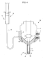
- Fig. 4 is a longitudinal sectional view showing a third modification of the objective-lens guiding device in Fig. 1.
- Fig. 5 is a longitudinal sectional view showing a fourth modification of the objective-lens guiding device in Fig. 1.
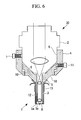
- Fig. 6 is a longitudinal sectional view showing a fifth modification of the objective-lens guiding device in Fig. 1.
- Fig. 7 is a longitudinal sectional view showing a sixth modification of the objective-lens guiding device in Fig. 1.
- Fig. 8 is a longitudinal sectional view showing a seventh modification of the objective-lens guiding device in Fig. 1.
- An objective-lens guiding device 1 and an
objective lens unit 30 according to a first embodiment of the present invention will be described below with reference to Fig. 1. - The
objective lens unit 30 according to this embodiment includes anobjective lens 2 having a narrow-diameter end portion 3 and the objective-lens guiding device 1 attached to theobjective lens 2. As shown in Fig. 1, the objective-lens guiding device 1 according to this embodiment, which is attached to theobjective lens 2 having the narrow-diameter end portion 3, includes asupport portion 4 which is secured to theobjective lens 2 and acylindrical portion 5 for accommodating the narrow-diameter end portion 3. - The
support portion 4 includes afitting portion 6 for fitting to the outer surface of theobjective lens 2; alocking screw 7 for securing thesupport portion 4 to theobjective lens 2 by pressing the outer surface of theobjective lens 2 in the radial direction, with thefitting portion 6 fitted to the outer surface of theobjective lens 2; and a female threadedportion 8 disposed at front side of theobjective lens 2. - The
cylindrical portion 5, which is a circular tube shaped member for accommodating the narrow-diameter end portion 3 of theobjective lens 2, has an opening 9 (front-end opening) at the front end thereof and a male threadedportion 10 at the rear end that engages with the female threadedportion 8 of thesupport portion 4. Thus, when thecylindrical portion 5 is rotated about the central axis thereof, thecylindrical portion 5 is made to finely translate relative to thesupport portion 4 along the central axis by virtue of the engagement of the female threadedportion 8 and the male threadedportion 10. - The
cylindrical portion 5 is preferably formed of a transparent material. Accordingly, the position of the narrow-diameter end portion 3 of theobjective lens 2 accommodated inside thecylindrical portion 5 can be checked from outside. - Between the
support portion 4 and thecylindrical portion 5, alocking screw 11 is provided for securing both of them at a suitable relative rotation. - The operation of the objective-lens guiding device 1 according to this embodiment, having such a configuration, will be described below.
- With the objective-lens guiding device 1 according to this embodiment, by fitting the
fitting portion 6 of thesupport portion 4 to the outer surface of theobjective lens 2 and tightening thelocking screw 7, thesupport portion 4 is secured to theobjective lens 2. In this state, thecylindrical portion 5 engaged with the female threadedportion 8 of thesupport portion 4 accommodates the narrow-diameter end portion 3 of theobjective lens 2, and afront end 5a of thecylindrical portion 5 is disposed farther toward the front than anend face 3a of the narrow-diameter end portion 3. - By loosening another
locking screw 11 provided between thesupport portion 4 and thecylindrical portion 5, it is possible to rotate thecylindrical portion 5 about its axis relative to thesupport portion 4. Because the male threadedportion 10 of thecylindrical portion 5 is engaged with the female threadedportion 8 of thesupport portion 4, when thecylindrical portion 5 is rotated about the axis relative to thesupport portion 4, thecylindrical portion 5 is displaced along the optical axis relative to thesupport portion 4 by an amount determined by the lead of the threadedportions locking screw 11, it is possible to secure thecylindrical portion 5 at a prescribed position relative to thesupport portion 4. - Because the working distance of the
objective lens 2 is set in advance, by pre-adjusting the distance between thefront end 5a of thecylindrical portion 5 and theend face 3a of the narrow-diameter end portion 3, it is possible to set in advance the focal position of theobjective lens 2 when thefront end 5a of thecylindrical portion 5 abuts against the examination target. In other words, by making the focal position of theobjective lens 2 coincident with the position of thefront end 5a of thecylindrical portion 5, it is possible to focus at the surface of the examination target against which thefront end 5a of thecylindrical portion 5 abuts. Also, by placing the focal position of theobjective lens 2 further towards the front than the position of thefront end 5a of thecylindrical portion 5, it is possible to focus at a deeper position than the surface of the examination target against which thefront end 5a of thecylindrical portion 5 abuts. - By doing so, simply by inserting the
cylindrical portion 5 accommodating the narrow-diameter end portion 3 inside the body of the examination target, such as a small laboratory animal, and abutting thefront end 5a of thecylindrical portion 5 against the examination site, such as an internal organ inside the body, it is possible to fix the focal position at a predetermined location with respect to thefront end 5a of thecylindrical portion 5. Therefore, it is not necessary to perform focusing each time the examination site is searched for, thus enabling a clear image to be acquired rapidly. - The objective-lens guiding device 1 according to this embodiment has been illustrated by a device in which the
opening 9 at thefront end 5a of thecylindrical portion 5 is open. However, when the examination site is relatively soft, the surface of the examination site bulges somewhat inside theopening 9 at thefront end 5a, and in some cases, it is not possible to dispose the focal position at the desired location. Thus, as shown in Fig. 2, the opening 9a at thefront end 5a of thecylindrical portion 5 is covered with a transparent film member (transparent member) 12 is disposed so as to stretch over theopening 9 to close it off. By doing so, during examination, thefilm member 12 is pushed in close contact with the surface of the examination site, which prevents it from bulging out. Thefilm member 12 can be easily fixed to thecylindrical portion 5 by means of a rubber ring or heat-shrinkable tube 13, etc. - As shown in Fig. 3, instead of the
film member 12, acover glass 14 may be fixed to theopening 9 at thefront end 5a of thecylindrical portion 5. With this configuration, because it is endowed with higher rigidity than thefilm member 12, it is possible to keep the surface of the examination site more flat. In this case, because it is not possible to make thecover glass 14 so thick, it is preferable to use sapphire glass, which has high strength. - In this embodiment, as shown in Fig. 4, a liquid supply apparatus (supply apparatus) 17, formed, for example, of a
syringe 15 and atube 16, may be connected to thesupport portion 4 to supply a liquid inside thecylindrical portion 5. In this case, it is possible to construct an immersion objective lens by filling the gap between the examination site and theend face 3a of the narrow-diameter end portion 3 with a liquid, such as water or immersion oil, which increases the numerical aperture, thus enabling clearer images to be acquired. It is particularly preferable to use water as the liquid. - By fixing the
tube 16 to thesupport portion 4, when thecylindrical portion 5 is rotated relative to thesupport portion 4 to adjust its position in the optical axis direction, thetube 16 does not move, thus facilitating replacement of thetube 16. Instead of this, it is possible to fix thetube 16 to thecylindrical portion 5 to function as a movable tube. In the drawing, reference symbols S is a sealing member for preventing leakage of liquid from between thesupport portion 4 and theobjective lens 2 and from between thesupport portion 4 and thecylindrical portion 5. - In this embodiment, the
cylindrical portion 5 is formed of a single part. Instead of this, however, as shown in Fig. 5, it may be separated into acylindrical portion 5 for accommodating the narrow-diameter end portion 3 of theobjective lens 2 and anintermediate member 18 for connecting to thesupport portion 4, and thecylindrical portion 5 may be provided in such a manner as to be attachable to and detachable from theintermediate member 18. By doing so, the narrow-diameter end portion 3 is covered by thecylindrical portion 5 attached to theintermediate member 18, and only thecylindrical portion 5 is in contact with the living organism when the narrow-diameter end portion 3 is inserted inside the body of the living organism under examination, such as a small laboratory animal. Therefore, by removing thecylindrical portion 5 from theintermediate member 18 after examination and replacing it, the narrow-diameter end portion 3 is always covered by thecylindrical portion 5 and kept clean, which can prevent infection or contamination. - As shown in Fig. 6, instead of the
cover glass 14 which is provided at thefront end 5a of thecylindrical portion 5, thetransparent film member 12 may be employed to cover and close off theopening 9 at thefront end 5a of thecylindrical portion 5. By doing so, it is possible to attach and detach thefilm member 12 while thecylindrical portion 5 is removed from theintermediate member 18, which allows the working efficiency to be improved. - In this embodiment, by engaging the male threaded
portion 10 provided on thecylindrical portion 5 or theintermediate member 18 with the female threadedportion 8 provided on thesupport portion 4, rotating thecylindrical portion 5 or theintermediate member 18 relative to thesupport portion 4 moves thecylindrical portion 5 or theintermediate member 18 in a direction along the optical axis. Instead of this, however, as shown in Fig. 7, by urging thecylindrical portion 5 with acoil spring 19 in a direction such that it retreats along the optical axis relative to thesupport portion 4 and by pressing atapered surface 21 provided on thecylindrical portion 5 with aset screw 20 engaged with thesupport portion 4, it is possible to employ a configuration in which thecylindrical portion 5 is made to advance against an urging force of thecoil spring 19. - The
support portion 4 is secured to theobjective lens 2 by the lockingscrew 7 in the configuration described above. Instead of this, however, it is possible to provide securing means such as a press-fit plunger or the like, having aball 22 and aspring 23, as shown in Fig. 7. By doing so, when thefitting portion 6 of thesupport portion 4 is fitted to theobjective lens 2, it engages with ahole 24 provided in the outer surface of theobjective lens 2 due to the urging force of theball 22 and thespring 23. Therefore, it is possible to secure the objective-lens guiding device 1 to theobjective lens 2 with a single action. - As shown in Fig. 8, a sheet member (securing member) 25 may be provided around the
cylindrical portion 5 of the type that can be attached to and detached from theintermediate member 18. Thissheet member 25 is formed of a biocompatible material, and it can be sewed to the skin of the small laboratory animal or the like under examination using, for example a needle and thread. - With this configuration, the
sheet member 25 is not sewed to the skin until the examination site is set, thus allowing thecylindrical portion 5 to be freely moved, and improving the ease of use. In addition, by sewing thesheet member 25 to the skin after the examination site is set and securing thecylindrical portion 5, it is possible to continuously observe the same location. - In this case, because the
cylindrical portion 5 is attached to theintermediate member 18 in such a manner that it can be attached and detached, after the examination site is set and thesheet member 25 is sewed to the skin, it is possible to remove thecylindrical portion 5 from theintermediate member 18 and leave thecylindrical portion 5 attached to the small laboratory animal under examination. Because thecylindrical portion 5 is extremely light since it covers just the narrow-diameter end portion 3, even when left attached, the free activity of the small laboratory animal or the like is not restricted. It is thus possible to perform examination over time while allowing normal activity of the small laboratory animal or the like.
Claims (8)
- An objective-lens guiding device comprising:a support portion secured to an objective lens having a narrow-diameter end portion; anda cylindrical portion configured to accommodate the narrow-diameter end portion,wherein the support portion supports the cylindrical portion so that a front end of the cylindrical portion is disposed at a location farther toward the front than an end face of the narrow-diameter end portion and so as to be capable of moving in an optical axis direction.
- An objective-lens guiding device according to Claim 1, further comprising a transparent member disposed so as to close off a front-end opening of the cylindrical portion.
- An objective-lens guiding device according to Claim 2, wherein the transparent member is formed of a film member covering the front-end opening of the cylindrical portion.
- An objective-lens guiding device according to Claim 2,
wherein the transparent member is formed of a cover glass secured to the front-end opening of the cylindrical portion. - An objective-lens guiding device according to Claim 1, further comprising:an intermediate member provided so as to be movable in the optical axis direction relative to the support portion,wherein the cylindrical portion is attached to the intermediate member in such a manner as to be attachable thereto and removable therefrom.
- An objective-lens guiding device according to Claim 1,
wherein a securing member configured to secure the cylindrical portion to an examination target is provided on the cylindrical portion. - An objective-lens guiding device according to Claim 1, further comprising a supply apparatus configured to supply liquid to the inside of the cylindrical portion.
- An objective lens unit comprising:an objective lens having a narrow-diameter end portion; andan objective-lens guiding device according to Claim 1.
Applications Claiming Priority (1)
| Application Number | Priority Date | Filing Date | Title |
|---|---|---|---|
| JP2006229719A JP5530051B2 (en) | 2006-08-25 | 2006-08-25 | Objective lens guide device and objective lens unit |
Publications (2)
| Publication Number | Publication Date |
|---|---|
| EP1891889A1 true EP1891889A1 (en) | 2008-02-27 |
| EP1891889B1 EP1891889B1 (en) | 2009-11-11 |
Family
ID=38828433
Family Applications (1)
| Application Number | Title | Priority Date | Filing Date |
|---|---|---|---|
| EP07015967A Not-in-force EP1891889B1 (en) | 2006-08-25 | 2007-08-14 | Objective-lens guiding device and objective lens unit |
Country Status (4)
| Country | Link |
|---|---|
| US (1) | US7787178B2 (en) |
| EP (1) | EP1891889B1 (en) |
| JP (1) | JP5530051B2 (en) |
| DE (1) | DE602007003153D1 (en) |
Citations (3)
| Publication number | Priority date | Publication date | Assignee | Title |
|---|---|---|---|---|
| WO1995010218A1 (en) * | 1993-10-08 | 1995-04-20 | Heartport, Inc. | Stereoscopic percutaneous visualization system |
| US5501217A (en) * | 1992-12-28 | 1996-03-26 | Tomey Corporation | Contact lens for intraocular observation |
| EP1524542A1 (en) * | 2003-10-17 | 2005-04-20 | Olympus Corporation | Objective lens insertion tool & objective optical system attachment device |
Family Cites Families (19)
| Publication number | Priority date | Publication date | Assignee | Title |
|---|---|---|---|---|
| US1889794A (en) * | 1931-01-03 | 1932-12-06 | Bausch & Lomb | Microscope objective |
| US3202049A (en) * | 1961-11-29 | 1965-08-24 | Bausch & Lomb | Liquid dispenser for microscope objective |
| US3837731A (en) * | 1973-06-22 | 1974-09-24 | Corning Glass Works | Oil dispenser for microscope objective |
| JPS6116526U (en) * | 1984-07-05 | 1986-01-30 | オリンパス光学工業株式会社 | Objective lens for microscope |
| JPH0761307B2 (en) * | 1986-06-24 | 1995-07-05 | 京セラ株式会社 | In-vivo member |
| JPH0614921B2 (en) * | 1989-09-29 | 1994-03-02 | 浜松ホトニクス株式会社 | Fluorescence observation device for biological tissue |
| JP2949653B2 (en) * | 1993-06-17 | 1999-09-20 | 株式会社モリテックス | Hard image scope |
| US5764409A (en) * | 1996-04-26 | 1998-06-09 | Alpha Innotech Corp | Elimination of vibration by vibration coupling in microscopy applications |
| JPH10258023A (en) * | 1997-03-21 | 1998-09-29 | Matsushita Electric Ind Co Ltd | Optical adapter for videoscope |
| JPH1147092A (en) * | 1997-07-29 | 1999-02-23 | D N Ee:Kk | Intraoral imaging device |
| JPH11113841A (en) * | 1997-10-09 | 1999-04-27 | Matsushita Electric Ind Co Ltd | Otoscope videoscope and otonose video scope system using the same |
| JP2000180731A (en) * | 1998-12-17 | 2000-06-30 | Hiroyuki Tanaka | Film bag |
| JP2001078951A (en) * | 1999-09-16 | 2001-03-27 | Olympus Optical Co Ltd | Cover sheath for endoscope |
| JP4914537B2 (en) * | 2000-04-19 | 2012-04-11 | オリンパス株式会社 | Sample support device applied to an inverted microscope |
| JP4872167B2 (en) * | 2000-07-13 | 2012-02-08 | サンスター株式会社 | Small local illuminator |
| JP4579563B2 (en) * | 2004-03-15 | 2010-11-10 | オリンパス株式会社 | Objective optical system fixing device |
| JP2005121947A (en) | 2003-10-17 | 2005-05-12 | Olympus Corp | Object lens insertion fixture, microscope and microscope system |
| JP4253592B2 (en) * | 2004-01-06 | 2009-04-15 | オリンパス株式会社 | Immersion objective lens, fluorescence analyzer and inverted microscope. |
| US7699477B2 (en) * | 2006-08-25 | 2010-04-20 | Olympus Corporation | Alignment method, alignment apparatus, and alignment screen for objective-lens guiding device |
-
2006
- 2006-08-25 JP JP2006229719A patent/JP5530051B2/en not_active Expired - Fee Related
-
2007
- 2007-08-14 EP EP07015967A patent/EP1891889B1/en not_active Not-in-force
- 2007-08-14 DE DE602007003153T patent/DE602007003153D1/en active Active
- 2007-08-20 US US11/894,507 patent/US7787178B2/en not_active Expired - Fee Related
Patent Citations (3)
| Publication number | Priority date | Publication date | Assignee | Title |
|---|---|---|---|---|
| US5501217A (en) * | 1992-12-28 | 1996-03-26 | Tomey Corporation | Contact lens for intraocular observation |
| WO1995010218A1 (en) * | 1993-10-08 | 1995-04-20 | Heartport, Inc. | Stereoscopic percutaneous visualization system |
| EP1524542A1 (en) * | 2003-10-17 | 2005-04-20 | Olympus Corporation | Objective lens insertion tool & objective optical system attachment device |
Also Published As
| Publication number | Publication date |
|---|---|
| DE602007003153D1 (en) | 2009-12-24 |
| EP1891889B1 (en) | 2009-11-11 |
| US7787178B2 (en) | 2010-08-31 |
| US20080051666A1 (en) | 2008-02-28 |
| JP2008052137A (en) | 2008-03-06 |
| JP5530051B2 (en) | 2014-06-25 |
Similar Documents
| Publication | Publication Date | Title |
|---|---|---|
| JP6726709B2 (en) | Endoscope cap | |
| EP2856955B1 (en) | Endoscopic surgery device and outer sleeve tube | |
| US20030088155A1 (en) | Fitting jig of endoscope hood member | |
| US11517180B2 (en) | Endoscope | |
| US20190150722A1 (en) | Washing tool and endoscope system | |
| JP2005121947A (en) | Object lens insertion fixture, microscope and microscope system | |
| EP1524542B1 (en) | Objective lens insertion tool & objective optical system attachment device | |
| US8169724B2 (en) | Objective lens adapter | |
| US9993138B2 (en) | Rigid endoscope set | |
| JPWO2015033905A1 (en) | Endoscopic surgical apparatus and mantle tube | |
| JP2005000640A (en) | Endoscope | |
| US7787178B2 (en) | Objective-lens guiding device and objective lens unit | |
| WO2000013570A1 (en) | Microscopy method and apparatus | |
| JP4789317B2 (en) | Endoscope device | |
| EP1892554A2 (en) | Alignment method, alignment apparatus, and alignment screen for objective-lens guiding device | |
| JP5962890B2 (en) | Identification tool for cytodiagnosis, cytodiagnosis method using this identification tool, and cytodiagnosis kit | |
| JP2530800Y2 (en) | Endoscope guide device | |
| JPH0228492Y2 (en) | ||
| JP3159515B2 (en) | Trocar | |
| JPH0724084Y2 (en) | Endoscope device | |
| JP2025096209A (en) | Observation device and method for observing the eye | |
| JPS60233607A (en) | Ocular device of endoscope | |
| GB2125985A (en) | Eyepiece for fiberscope | |
| JP2011036522A (en) | Endoscope for biopsy diagnosis |
Legal Events
| Date | Code | Title | Description |
|---|---|---|---|
| PUAI | Public reference made under article 153(3) epc to a published international application that has entered the european phase |
Free format text: ORIGINAL CODE: 0009012 |
|
| AK | Designated contracting states |
Kind code of ref document: A1 Designated state(s): AT BE BG CH CY CZ DE DK EE ES FI FR GB GR HU IE IS IT LI LT LU LV MC MT NL PL PT RO SE SI SK TR |
|
| AX | Request for extension of the european patent |
Extension state: AL BA HR MK YU |
|
| 17P | Request for examination filed |
Effective date: 20080430 |
|
| RIN1 | Information on inventor provided before grant (corrected) |
Inventor name: FUJIWARA, MASATO Inventor name: OKADOME, TATSUYA Inventor name: ONDA, NOBUHIKO Inventor name: SAKAI, IKUKO Inventor name: NATORI, YASUAKI |
|
| 17Q | First examination report despatched |
Effective date: 20080527 |
|
| AKX | Designation fees paid |
Designated state(s): DE FR GB |
|
| GRAP | Despatch of communication of intention to grant a patent |
Free format text: ORIGINAL CODE: EPIDOSNIGR1 |
|
| GRAS | Grant fee paid |
Free format text: ORIGINAL CODE: EPIDOSNIGR3 |
|
| GRAA | (expected) grant |
Free format text: ORIGINAL CODE: 0009210 |
|
| AK | Designated contracting states |
Kind code of ref document: B1 Designated state(s): DE FR GB |
|
| REG | Reference to a national code |
Ref country code: GB Ref legal event code: FG4D |
|
| REF | Corresponds to: |
Ref document number: 602007003153 Country of ref document: DE Date of ref document: 20091224 Kind code of ref document: P |
|
| PLBE | No opposition filed within time limit |
Free format text: ORIGINAL CODE: 0009261 |
|
| STAA | Information on the status of an ep patent application or granted ep patent |
Free format text: STATUS: NO OPPOSITION FILED WITHIN TIME LIMIT |
|
| 26N | No opposition filed |
Effective date: 20100812 |
|
| REG | Reference to a national code |
Ref country code: FR Ref legal event code: ST Effective date: 20110502 |
|
| PG25 | Lapsed in a contracting state [announced via postgrant information from national office to epo] |
Ref country code: FR Free format text: LAPSE BECAUSE OF NON-PAYMENT OF DUE FEES Effective date: 20100831 |
|
| PGFP | Annual fee paid to national office [announced via postgrant information from national office to epo] |
Ref country code: GB Payment date: 20110810 Year of fee payment: 5 |
|
| GBPC | Gb: european patent ceased through non-payment of renewal fee |
Effective date: 20120814 |
|
| PG25 | Lapsed in a contracting state [announced via postgrant information from national office to epo] |
Ref country code: GB Free format text: LAPSE BECAUSE OF NON-PAYMENT OF DUE FEES Effective date: 20120814 |
|
| PGFP | Annual fee paid to national office [announced via postgrant information from national office to epo] |
Ref country code: DE Payment date: 20170808 Year of fee payment: 11 |
|
| REG | Reference to a national code |
Ref country code: DE Ref legal event code: R119 Ref document number: 602007003153 Country of ref document: DE |
|
| PG25 | Lapsed in a contracting state [announced via postgrant information from national office to epo] |
Ref country code: DE Free format text: LAPSE BECAUSE OF NON-PAYMENT OF DUE FEES Effective date: 20190301 |