EP1891810B1 - Method and apparatus for coding motion and prediction weighting parameters - Google Patents
Method and apparatus for coding motion and prediction weighting parameters Download PDFInfo
- Publication number
- EP1891810B1 EP1891810B1 EP06771414.7A EP06771414A EP1891810B1 EP 1891810 B1 EP1891810 B1 EP 1891810B1 EP 06771414 A EP06771414 A EP 06771414A EP 1891810 B1 EP1891810 B1 EP 1891810B1
- Authority
- EP
- European Patent Office
- Prior art keywords
- weighting parameters
- transformed
- prediction
- original
- parameters
- Prior art date
- Legal status (The legal status is an assumption and is not a legal conclusion. Google has not performed a legal analysis and makes no representation as to the accuracy of the status listed.)
- Active
Links
- 230000033001 locomotion Effects 0.000 title claims description 102
- 238000000034 method Methods 0.000 title claims description 57
- 238000005192 partition Methods 0.000 claims description 56
- 239000013598 vector Substances 0.000 claims description 30
- 230000001131 transforming effect Effects 0.000 claims description 12
- 238000013139 quantization Methods 0.000 claims description 10
- 238000004519 manufacturing process Methods 0.000 claims description 2
- 238000012545 processing Methods 0.000 description 60
- 230000008569 process Effects 0.000 description 30
- 238000010586 diagram Methods 0.000 description 13
- 238000006073 displacement reaction Methods 0.000 description 11
- 230000006870 function Effects 0.000 description 10
- 230000015654 memory Effects 0.000 description 8
- 230000002123 temporal effect Effects 0.000 description 7
- 230000009466 transformation Effects 0.000 description 7
- 238000000844 transformation Methods 0.000 description 7
- 230000007704 transition Effects 0.000 description 7
- 230000008901 benefit Effects 0.000 description 6
- 238000003860 storage Methods 0.000 description 6
- 230000007246 mechanism Effects 0.000 description 5
- 230000003287 optical effect Effects 0.000 description 5
- 238000012360 testing method Methods 0.000 description 5
- 208000018375 cerebral sinovenous thrombosis Diseases 0.000 description 4
- 230000000875 corresponding effect Effects 0.000 description 4
- 238000004891 communication Methods 0.000 description 3
- 241000023320 Luma <angiosperm> Species 0.000 description 2
- 239000000654 additive Substances 0.000 description 2
- 230000000996 additive effect Effects 0.000 description 2
- 230000006835 compression Effects 0.000 description 2
- 238000007906 compression Methods 0.000 description 2
- 238000004590 computer program Methods 0.000 description 2
- 230000002596 correlated effect Effects 0.000 description 2
- 238000013500 data storage Methods 0.000 description 2
- 238000009826 distribution Methods 0.000 description 2
- OSWPMRLSEDHDFF-UHFFFAOYSA-N methyl salicylate Chemical compound COC(=O)C1=CC=CC=C1O OSWPMRLSEDHDFF-UHFFFAOYSA-N 0.000 description 2
- 230000011664 signaling Effects 0.000 description 2
- 230000003068 static effect Effects 0.000 description 2
- 238000012935 Averaging Methods 0.000 description 1
- 101150039623 Clip1 gene Proteins 0.000 description 1
- 230000009471 action Effects 0.000 description 1
- 238000004458 analytical method Methods 0.000 description 1
- 238000003491 array Methods 0.000 description 1
- 230000005540 biological transmission Effects 0.000 description 1
- 230000001276 controlling effect Effects 0.000 description 1
- 230000003993 interaction Effects 0.000 description 1
- 239000004973 liquid crystal related substance Substances 0.000 description 1
- 238000013507 mapping Methods 0.000 description 1
- 230000000063 preceeding effect Effects 0.000 description 1
- 230000000644 propagated effect Effects 0.000 description 1
- 230000002441 reversible effect Effects 0.000 description 1
- 239000000126 substance Substances 0.000 description 1
- 238000006467 substitution reaction Methods 0.000 description 1
Images


Classifications
-
- H—ELECTRICITY
- H04—ELECTRIC COMMUNICATION TECHNIQUE
- H04N—PICTORIAL COMMUNICATION, e.g. TELEVISION
- H04N19/00—Methods or arrangements for coding, decoding, compressing or decompressing digital video signals
- H04N19/50—Methods or arrangements for coding, decoding, compressing or decompressing digital video signals using predictive coding
- H04N19/503—Methods or arrangements for coding, decoding, compressing or decompressing digital video signals using predictive coding involving temporal prediction
- H04N19/51—Motion estimation or motion compensation
- H04N19/577—Motion compensation with bidirectional frame interpolation, i.e. using B-pictures
-
- H—ELECTRICITY
- H04—ELECTRIC COMMUNICATION TECHNIQUE
- H04N—PICTORIAL COMMUNICATION, e.g. TELEVISION
- H04N19/00—Methods or arrangements for coding, decoding, compressing or decompressing digital video signals
- H04N19/46—Embedding additional information in the video signal during the compression process
- H04N19/463—Embedding additional information in the video signal during the compression process by compressing encoding parameters before transmission
-
- H—ELECTRICITY
- H04—ELECTRIC COMMUNICATION TECHNIQUE
- H04N—PICTORIAL COMMUNICATION, e.g. TELEVISION
- H04N19/00—Methods or arrangements for coding, decoding, compressing or decompressing digital video signals
- H04N19/50—Methods or arrangements for coding, decoding, compressing or decompressing digital video signals using predictive coding
- H04N19/587—Methods or arrangements for coding, decoding, compressing or decompressing digital video signals using predictive coding involving temporal sub-sampling or interpolation, e.g. decimation or subsequent interpolation of pictures in a video sequence
-
- H—ELECTRICITY
- H04—ELECTRIC COMMUNICATION TECHNIQUE
- H04N—PICTORIAL COMMUNICATION, e.g. TELEVISION
- H04N19/00—Methods or arrangements for coding, decoding, compressing or decompressing digital video signals
- H04N19/60—Methods or arrangements for coding, decoding, compressing or decompressing digital video signals using transform coding
- H04N19/61—Methods or arrangements for coding, decoding, compressing or decompressing digital video signals using transform coding in combination with predictive coding
-
- H—ELECTRICITY
- H04—ELECTRIC COMMUNICATION TECHNIQUE
- H04N—PICTORIAL COMMUNICATION, e.g. TELEVISION
- H04N19/00—Methods or arrangements for coding, decoding, compressing or decompressing digital video signals
- H04N19/70—Methods or arrangements for coding, decoding, compressing or decompressing digital video signals characterised by syntax aspects related to video coding, e.g. related to compression standards
Definitions
- the present invention relates to the field of video coding and decoding; more particularly, the present invention relates to coding motion and prediction weighting parameters.
- Motion Compensated (Inter-frame) prediction is a vital component of video coding schemes and standards such as MPEG-1/2, and H.264 (or JVT or MPEG AVC) due to the considerable benefit it could provide in terms of coding efficiency.
- motion compensation was performed by primarily, if not only, considering temporal displacement. More specifically, standards such as MPEG-1, 2, and MPEG-4 consider two different picture types for inter-frame prediction, predictive (P) and bi-directionally predicted (B) pictures. Such pictures are partitioned into a set of non-overlapping blocks, each one associated with a set of motion parameters.
- Figure 1A illustrates an example of motion compensation in P pictures.
- Figure 1B illustrates an example of motion compensation in B pictures. In the later case, essentially prediction is formed by averaging both predictions from these two references, using equal weighting factors of (1 ⁇ 2, 1 ⁇ 2).
- the predicted signal is also scaled and/or adjusted using two new parameters w and o .
- the sample with brightness value I ( x , y , t ) at position ( x , y ) at time t is essentially constructed as w ⁇ I ( x + dx, y + dy, t' ) + o , where dx and dy are the spatial displacement parameters (motion vectors).
- these new weighting parameters could also considerably increase the overhead bits required for representing motion information, therefore potentially reducing the benefit of such strategies.
- the ITU-H.264 (or JVT or ISO MPEG4 AVC) video compression standard has adopted certain weighted prediction tools that could take advantage of temporal brightness variations and could improve performance.
- the H.264 video coding standard is the first video compression standard to adopt weighted prediction (WP) for motion compensated prediction.
- WP weighted prediction
- Motion compensated prediction may consider multiple reference pictures, with a reference picture index coded to indicate which of the multiple reference pictures is used.
- P pictures or P slices
- B pictures two separate reference picture lists are managed, list 0 and list 1.
- B pictures or B slices
- uni-prediction using either list 0 or list 1, or bi-prediction using both list 0 and list 1 is allowed.
- the list 0 and the list 1 predictors are averaged together to form a final predictor.
- the H.264 weighted prediction tool allows arbitrary multiplicative weighting factors and additive offsets to be applied to reference picture predictions in both P and B pictures. Use of weighted prediction is indicated in the sequence parameter set for P and SP slices. There are two weighted prediction modes; explicit mode, which is supported in P, SP, and B slices, and implicit mode, which is supported in B slices only.
- weighted prediction parameters are coded in the slice header.
- a multiplicative weighting factor and an additive offset for each color component may be coded for each of the allowable reference pictures in list 0 for P slices and list 0 and list 1 for B slices.
- the syntax also allows different blocks in the same picture to make use of different weighting factors even when predicted from the same reference picture store. This can be made possible by using reordering commands to associate more than one reference picture index with a particular reference picture store.
- weighting factors are not explicitly transmitted in the slice header, but instead are derived based on relative distances between the current picture and its reference pictures. This mode is used only for bi-predictively coded macroblocks and macroblock partitions in B slices, including those using direct mode.
- H.264 video coding standard enables the use of multiple weights for motion compensation, such use is considerably limited by the fact that the standard only allows signalling of up to 16 possible references for each list at the slice level. This implies that only a limited number of weighting factors could be considered. Even if this restriction did not apply, it could be potentially inefficient if not difficult to signal all possible weighting parameters that may be necessary for encoding a picture.
- weighting parameters for each reference are independently coded without the consideration of a prediction mechanism, while the additional overhead for signalling the reference indices may also be significant. Therefore H.264 and the method disclosed in Kamikura, et al., "Global Brightness-Variation Compensation for Video Coding," IEEE Trans on CSVT, vol. 8, pp. 988-1000, December 1998 are more appropriate for global than local brightness variations. In other words, these tools tend to work well for global brightness variations, but due to certain limitations little gain can be achieved in the presence of significant local brightness variation.
- US2004/0057523, Koto et al discloses encoding of a video picture by adaptively switching between use of a plurality of decoded video signals as reference frames and generation of a predictive macroblock picture from a plurality of reference frames for each macroblock.
- Said predictive macroblock can be generated by using weight factors which vary for each reference frame.
- a specific example of encoding information of weight factors in the header data of a video frame to be encoded or in the header of a slice includes division by a denominator (see paragraphs [0260] to [0268]).
- M - 1 is equal to wQ k-1 minus said sum of all of the original weighting parameters divided by the number of original weighting parameters M; performing motion compensation to generate a prediction using said M motion vectors and said M original weighting parameters; producing a residual by subtracting said prediction from said input block of image data; transforming said residual using a discrete cosine transform to create a 2-D array of transformed coefficients; quantizing said transformed coefficients; and variable length coding said transformed weighting parameters and said quantized transformed coefficients to generate a bitstream.
- M - 1 is equal to wQ k-1 minus said sum of all of the original weighting parameters divided by the number of original weighting parameters M, wherein said sum is equal to a constant; a subtractor to subtract said prediction from the input block of image data to create a residual; a second transform unit to transform said residual using a discrete cosine transform to create a 2-D array of transformed coefficients; a quantizer to quantize said transformed coefficients; and a variable length coder to code said transformed weighting parameters and said quantized transformed coefficients to generate a bitstream.
- M - 1 is equal to wQ k-1 minus said sum of all of the original weighting parameters divided by the number of original weighting parameters M; performing motion compensation to generate a prediction using said M motion vectors and said M original weighting parameters; producing a residual by subtracting said prediction from said input block of image data; transforming said residual using a discrete cosine transform to create a 2-D array of transformed coefficients; quantizing said transformed coefficients; and variable length coding said transformed weighting parameters and said quantized transformed coefficients to generate a bitstream.
- the coding scheme includes a transform process between pairs of weighting parameters associated with each reference for each block that is being subjected to motion compensated prediction.
- the transform process causes a transform to be applied to the weighting parameters.
- the transformed weighting parameters are signaled for every block using a prediction method and are coded using a zero tree coding structure. This reduces the overhead required for coding these parameters. While the methods described herein are primarily aimed at bi-predictive partitions. Some of the concepts could also apply to uni-predicted partitions.
- the interactions between uni-predicted and bi-predicted partitions are used to further improve efficiency. Special consideration is also made for bi-predictive pictures or slices, where a block may be predicted from a different list or both lists.
- the coding scheme is further extended by combining and considering both global and local weighting parameters. Additional weighting parameters transmitted at the sequence, picture, or slice level are also optionally considered.
- variable granularity dynamic range of such parameters is also taken into account.
- weighting parameters are finely adjustable, which provides additional benefits in terms of coding efficiency.
- the present invention also relates to apparatus for performing the operations herein.
- This apparatus may be specially constructed for the required purposes, or it may comprise a general purpose computer selectively activated or reconfigured by a computer program stored in the computer.
- a computer program may be stored in a computer readable storage medium, such as, but is not limited to, any type of disk including floppy disks, optical disks, CD-ROMs, and magnetic-optical disks, read-only memories (ROMs), random access memories (RAMs), EPROMs, EEPROMs, magnetic or optical cards, or any type of media suitable for storing electronic instructions, and each coupled to a computer system bus.
- a machine-readable medium includes any mechanism for storing or transmitting information in a form readable by a machine (e.g., a computer).
- a machine-readable medium includes read only memory ("ROM”); random access memory (“RAM”); magnetic disk storage media; optical storage media; flash memory devices; electrical, optical, acoustical or other form of propagated signals (e.g., carrier waves, infrared signals, digital signals, etc.); etc.
- Embodiments of the present invention include a coding scheme that uses motion compensation that includes weighted prediction.
- the weighting parameters associated with a prediction are transformed and then coded with the offset associated with the prediction.
- the decoding process is a reverse of the encoding process.
- FIG. 2 is a flow diagram of one embodiment of an encoding process.
- the process is performed by processing logic that may comprise hardware (circuitry, dedicated logic, etc.), software (such as is run on a general purpose computer system or a dedicated machine), or a combination of both.
- processing logic may comprise hardware (circuitry, dedicated logic, etc.), software (such as is run on a general purpose computer system or a dedicated machine), or a combination of both.
- the process begins by processing logic generating weighting parameters for multi-hypothesis partitions (e.g., bi-predictive partitions) as part of performing motion estimation (processing block 201).
- the weighting parameters comprise at least one pair of a set of weighting parameters for each partition (block) of a frame being encoded.
- the weights for multiple pairs of transformed weighting parameters sum to a constant.
- different weighting factors for at least two partitions of the frame are used.
- the weighting parameters compensate for local brightness variations.
- the weighted prediction parameters have variable fidelity levels.
- the variable fidelity levels are either predefined or signaled as part of a bitstream that includes an encoded representation of the transformed weighting parameters.
- one group of weighting parameters have a higher fidelity than those of another group of weighting parameters.
- processing logic applies a transform to the weighting parameters to create transformed weighting parameters (processing block 202).
- transforming the weighting parameters comprises applying a transform to at least two weighting parameters associated with each reference.
- processing logic After applying a transform to the weighting parameters, processing logic codes transformed weighting parameters and an offset (processing block 203).
- the transformed weighting parameters are coded with at least one offset using variable length encoding.
- the variable length encoding may use a zero tree coding structure.
- Variable length encoding may comprise Huffman coding or arithmetic coding.
- coding the transformed weighting parameters comprises differentially coding using predictions based on one of a group consisting of transformed coefficients of neighboring partitions or predetermined weighting parameters.
- the predetermined weighting parameter are used when no neighboring partition exists for a prediction.
- the predetermined weighting parameters may be default weighting parameters or globally transmitted weighting parameters.
- FIG 3 is a flow diagram of one embodiment of a decoding process.
- a decoding process is used to decode information encoded as part of the encoding process of Figure 2 .
- the process is performed by processing logic that may comprise hardware (circuitry, dedicated logic, etc.), software (such as is run on a general purpose computer system or a dedicated machine), or a combination of both.
- variable length decoding may comprise Huffman coding or arithmetic coding.
- processing logic applies an inverse transform to the transformed weighting parameters (processing block 302).
- the inverse transformed weighting parameters comprise at least two weighting parameters associated with a reference.
- processing logic reconstructs frame data using motion compensation in conjunction with inverse transformed weighting parameters (processing block 303).
- Weighted prediction is useful for encoding video data that comprises fades, cross-fades/dissolves, and simple brightness variations such as flashes, shading changes etc.
- Bi-prediction and multi-hypothesis prediction in general
- Conventional bi-prediction tends to use equal weights (i.e. 1 ⁇ 2) for all predictions.
- one signal is more correlated than another, for example due to temporal distance or quantization or other noise introduced/existing within each signal.
- I x y t weight 0 ⁇ I x + dx 0 , y + dy 0 , t 0 + weight 1 ⁇ I x + dx 1 , y + dy 1 , t 1 + offset
- weight k , dx k , dy k , and t k are the weights, horizontal and vertical displacement, and time corresponding to prediction from list k, and offset is the offset parameter.
- c is a constant.
- the constant c is equal to 1. This could basically also be seen as the computation of the weighted average between all prediction samples.
- the N-bit quantized parameters wQ 0 and wQ 1 are used.
- N is 6 bits.
- ⁇ denotes a left bit shift operator and >> denotes a right bit shift operator.
- 1 ⁇ N is used as a default predictor for B_wQ 0 .
- the parameters B_wQ 0 and B_wQ 1 are coded as is.
- the parameters B_wQ 0 and B_wQ 1 are differentially coded by considering the values of B_wQ 0 and B_wQ 1 from neighboring bi-predicted partitions. If no such partitions exist, then these parameters could be predicted using default values dB_wQ 0 and dB_wQ 1 (e.g., both values could be set to 0).
- Figure 10 illustrates a transform process of the weighting parameters for coding frames using bi-prediction.
- transform 1001 receives the quantized weighting parameters wQ 0 and wQ 1 and produces transformed weighting parameters B_wQ 0 and B_wQ 1 , respectively.
- These transformed weighting parameters are variable length encoded using variable length encoder 1002 along with the offset. Thereafter, the encoded weighting parameters are sent as part of the bitstream to a decoder.
- the variable length decoder 1103 decodes the bitstream and produces the transformed weighting parameters B_wQ 0 and B_wQ 1 , along with the offset.
- Inverse transform 1004 inverse transforms the transformed weighting parameters to produce the quantized version of the weighting parameters wQ 0 and wQ 1 .
- Weighting parameter wQ 0 is multiplied by a motion -compensated sample x 0 by multiplier 1006 to produce an output which is input into adder 1007.
- Weighting parameter wQ 1 is multiplied by a motion-compensated sample x 1 using multiplier 1005.
- the result from multiplier 1005 is added to the output of multiplier 1006 and to 2 N-1 using adder 1007.
- the output of adder 1007 is divided by 2 N by divider 1008. The result of the division is added to the offset using adder 1009 to produce a predicted sample x'.
- the present invention is not limited to the bi-prediction case; it is equally applicable to the multi-hypothesis case where M different hypothesis are used.
- Figure 11 illustrates the process for weighting parameters for the multi-hypothesis case.
- the same arrangement as shown in Figure 10 is shown in Figure 11 with the difference that sets of two or more weighting parameters are transformed by transform 1101 and variable length encoder 1102 encodes sets of quantized weighting parameters along with one offset for each set
- variable length decoder 1103 decodes the bitstream to produce sets of transformed weighting parameters.
- Each set of transformed weighting parameters is inverse transformed by an inverse transform 1104, the output of which are a combined to produce a predicted sample x' in the same way as is done in Figure 10 .
- Adder 1107 adds the results of all multiplications for all of the quantized weighting parameters.
- the same picture or slice may have a combination of both bi-predicted and uni-predicted partitions.
- a bi-predicted partition it is possible for a bi-predicted partition to have a uni-predicted neighbor using either list0 or list1 prediction, or even a uni-predicted partition using listX (where X could be 0 or 1) having neighbors using a different list.
- listX where X could be 0 or 1
- motion vectors within a bi-predicted partition could still be correlated with motion vectors of a uni-predicted partition, this is less likely to be the case for motion vectors of different lists, but also of weighting parameters using different number of hypotheses (i.e.
- weights from bi-predicted partitions may have little relationship with weights from uni-predicted partitions, while a weight and motion vector from a uni-predicted partition using list 0, may have little relationship with these parameters from another partition using list 1).
- all weights from a given prediction mode (list0, list1, and bi-predicted) are restricted to be only predicted from adjacent partitions in the same mode.
- all R neighbors (Neigh 0 , Neigh 1 ,...
- a function used for f for example, is the median value of all predictors.
- a function such as the mean, consideration of only the top or left neighbors based on the reference frame they use or/and a predefined cost, etc.
- Neigh J uses a different prediction type, then it may be excluded from this prediction process.
- no predictions are available, then default values, as previously discussed could be used as a predictor.
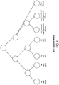
- FIGs 4 and 5 represent two possible trees with the node information that may be encoded .
- FIG 4 an example parent-child relationship for encoding of bi-prediction motion information is shown.
- nodes are segmented based on lists, with the horizontal and vertical motion vector displacement difference for ListO having a common parent node and the horizontal and vertical motion vector displacement difference for List1 having a common parent node.
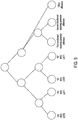
- Figure 5 motion is segmented based on motion vector component. In this case, the horizontal motion vector displacement difference for both ListO and List1 have a common parent node, while the vertical motion vector displacement difference for both ListO and List1 have a common parent mode.
- the trees described in Figure 4 and 5 containing both node type data and leaf indices data may be encoded (and subsequently decoded) using tree coding (e.g., zero tree coding) as described in U.S. Patent Application No. 11/172,052 , entitled “Method and Apparatus for Coding Positions of Coefficients,” filed June 29, 2005.
- tree coding e.g., zero tree coding
- Default values for a given prediction type do not have to be fixed.
- a set of global/default parameters are used and coded such as the ones used by the H.264 explicit mode, or alternatively derive these parameters using a mechanism similar to that of the H.264 implicit mode.
- the method or parameters could be signaled at the picture or slice level.
- FIG. 9 is a flow diagram of one embodiment for a process of using global and local weighting jointly.
- the process is performed by processing logic that may comprise hardware (circuitry, dedicated logic, etc.), software (such as is run on a general purpose computer system or a dedicated machine), or a combination of both.
- the process begins by setting default weighting parameters (processing block 901).
- default weighting parameters are ⁇ DScale L0 , DOffset L0 ⁇ .
- the weighting parameters are ⁇ DScale L1 , DOffset L1 ⁇ .
- the default weighting parameters are ⁇ DScale Bi_L0 , DScale Bi_L1 ,DOffset ⁇ .
- processing logic tests whether the block is a bi-prediction block (processing block 903). If so, processing logic transitions to processing block 904 where the processing logic tests whether there are any available bi-prediction predictors. If there are, processing logic computes the weighting parameter predictors using neighbors using a function f bipred (Neigh 0 .... Neigh 1 ) (processing block 905) and processing continues to processing block 914. If there are no available bi-prediction predictors, processing logic sets the weighting parameters to the default ⁇ DScale Bi_L0 , DScale Bi_L1 ,DOffset ⁇ (processing block 906) and the processing transitions to processing block 914.
- processing transitions to processing block 911 where the processing logic tests whether there are any available List1 prediction predictors. If there are, processing logic computes the weighting parameter predictors using neighbors f L0 (Neigh 0 ....Neigh 1 ) (processing block 912) and processing continues to processing block 914. If there are no available List1 predictors, processing logic sets the weighting parameters to the default values ⁇ DScale L1 , DOffset L1 ⁇ (processing block 913) and the processing transitions to processing block 914.
- processing logic decodes the weighting parameters. Thereafter, the weighting parameters predictors are added to the weighting parameters (processing block 915). The process then repeats for each block in the frame, and when each block in the frame has been processed, the process ends.
- bi-predicted weights could have different dynamic range, while the parameters luma_bipred_weight_type and chroma_bipred_weight_type are used to control the method that is to be used for deriving the weights. More specifically for luma, if luma_bipred_weight__type is set to 0, then the default 1 ⁇ 2 weight is used. If 1, then implicit mode is used, while if 2, the uniprediction weights are used instead as is currently done in H.264 explicit mode. Finally, if 3, weighting parameters are transmitted explicitly within this header. Table 1 Proposed Prediction Weight Table Syntax pred_weight_table() ⁇ C Descriptor //!
- fidelity of the weighting and offset parameters could be fixed, i.e. a weighting parameter is uniformly quantized to N bits, non uniform quantization may instead be more efficient and appropriate to better handle different variations within a frame.
- a finer fidelity is used for smaller weighting or offset parameters, whereas fidelity is increased for larger parameters.
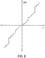
- equation 17 (or the more generic equation 18) allows for increased flexibility in terms of representing the fidelity of the weighting parameters. Note also that the operation a ⁇ x could indicate not only a multiply, but also an integer or floating point divide (i.e. assume that a is less than 1). Figure 8 is an example of the relationship between the representation and the true value of the weighting parameter.
- the parameters are determined by performing a pre-analysis of the frame or sequence, generating the distribution of the weighting parameters, and approximating the distribution with g(x) (i.e. using a polynomial approximation).
- Figure 12 illustrates the transform process of the weighting parameters for bi-prediction with controlled fidelity.
- the process is the same as in Figure 10 , with the exception that each of the transformed weighting parameters output from transform 1001 isn't input directly into variable-length encoder 1002, along with the offset. Instead, they are input into functions, the output of which are input to variable length encoder 1002. More specifically, transform weighting parameter B_wQ 0 is input into function g 0 (x) to produce x 0 . More specifically, transform weighting parameter B_wQ 1 is input into function g 1 (x) to produce x 1 (1202). The offset is also subjected to function g o (x) to produce x 2 (1203).
- decoder 1003 which are x 0 , x 1 and x 2 , are input into functions g 0 ⁇ 1 x g 1 ⁇ 1 x and g 0 ⁇ 1 x which produce the transformed weighting parameters in the offset. Thereafter, these are handled in the same manner as shown in Figure 10 .
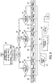
- Figure 6 is a block diagram of one embodiment of an encoder.
- the encoder first divides the incoming bitstream into rectangular arrays, referred to as macroblocks. For each macroblock, the encoder then chooses whether to use intra-frame or inter-frame coding.
- Intra-frame coding uses only the information contained in the current video frame and produces a compressed result referred to as an I-frame.
- Intra-frame coding can use information of one or more other frames, occurring before or after the current frame. Compressed results that only use data from previous frames are called P-frames, while those that use data from both before and after the current frame are called B-frames.
- video 601 is input into the encoder.
- frames of video are input into DCT 603.
- DCT 603 performs a 2D discrete cosign transform (DCT) to create DCT coefficients.
- the coefficients are quantized by quantizer 604.
- the quantization performed by quantizer 604 is weighted by scaler.
- the quantizer scaler parameter QP takes values from 1 to 31. The QP value can be modified in both picture and macroblock levels.
- VLC 605 performs entropy coding by using Huffman coding or arithmetic coding.
- reordering may be performed in which quantized DCT coefficients are zigzag scanned so that a 2D array of coefficients is converted into a 1D array of coefficients in a manner well-known in the art.
- This may be followed by run length encoding in which the array of reordered quantized coefficients corresponding to each block is encoded to better represent zero coefficients.
- each nonzero coefficient is encoded as a triplet (last, run, level), where "last" indicates whether this is the final nonzero coefficient in the block, "run” signals the preceeding 0 coefficients and "level” indicates the coefficients sign and magnitude.
- a copy of the frames may be saved for use as a reference frame. This is particularly the case of I or P frames.
- the quantized coefficients output from quantizer 604 are inverse quantized by inverse quantizer 606.
- An inverse DCT transform is applied to the inverse quantized coefficients using IDCT 607.
- the resulting frame data is added to a motion compensated predication from motion compensation (MC) unit 609 in the case of a P frame and then the resulting frame is filtered using loop filter 612 and stored in frame buffer 611 for use as a reference frame.
- MC motion compensation
- the data output from IDCT 607 is not added to a motion compensation prediction from MC unit 609 and is filtered using loop filter 612 and stored in frame buffer 611.
- the P frame is coded with interprediction from previous a I or P frame, which is referred to commonly in the art as the reference frame.
- the interprediction is performed by motion estimation (ME) block 610 and motion compensation unit 609.
- motion estimation unit 610 uses the reference frame from frame store 611 and the input video 601, motion estimation unit 610 searches for a location of a region in the reference frame that best matched the current macro block in the current frame. As discussed above, this includes not only determining a displacement, but also determining weighting parameters (WP) and an offset. The displacement between the current macroblock and the compensation region in the reference frame, along with the weighting parameters and the offset is called the motion vector.
- WP weighting parameters
- the motion vectors for motion estimation unit 610 are sent to motion compensation unit 609.
- the prediction is subtracted from the current macroblock to produce a residue macroblock using subtractor 602.
- the residue is then encoded using DCT 603, quantizer 604 and VLC 605 as described above.
- Motion estimation unit 610 outputs the weighting parameters to VLC 605 for variable length encoding 605.
- the output of VLC 605 is bitstream 620.
- Figure 7 is a block diagram of one embodiment of a decoder.
- bitstream 701 is received by variable length decoder 702 which performs variable length decoding.
- the output of variable length decoding is sent to inverse quantizer 703 which performs an inverse quantization operation that is the opposite of the quantization performed by quantizer 604.
- the output of inverse quantizer 703 comprise coefficients that are inverse DCT transformed by IDCT 704 to produce image data.
- IDCT 704 In the case of I frames, the output of IDCT 704 is simply filtered by loop filter 721, stored in frame buffer 722 and eventually output as output 760.
- the image data output from IDCT 704 is added to the prediction from motion compensation unit 710 using adder 705.
- Motion compensation unit 710 uses the output from variable length decoder 722, which includes the weighting parameters discussed above, as well as reference frames from frame buffer 722.
- the resulting image data output from adder 705 is filtered using loop filter 721 and stored in frame buffer 722 for eventual output as part of output 760.
- embodiments of the present invention allows improved representation of weighting parameters for bi-predictive partitions and improved coding efficiency (i.e. in terms of increased PSNR for a given bitrate) in the presence of brightness variations, or/and cross fades.
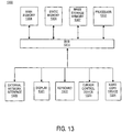
- Figure 13 is a block diagram of an exemplary computer system that may perform one or more of the operations described herein.
- computer system 1300 may comprise an exemplary client or server computer system.
- Computer system 1300 comprises a communication mechanism or bus 1311 for communicating information, and a processor 1312 coupled with bus 1311 for processing information.
- Processor 1312 includes a microprocessor, but is not limited to a microprocessor, such as, for example, PentiumTM, PowerPCTM, AlphaTM, etc.
- System 1300 further comprises a random access memory (RAM), or other dynamic storage device 1304 (referred to as main memory) coupled to bus 1311 for storing information and instructions to be executed by processor 1312.
- main memory dynamic storage device 1304
- Main memory 1304 also may be used for storing temporary variables or other intermediate information during execution of instructions by processor 1312.
- Computer system 1300 also comprises a read only memory (ROM) and/or other static storage device 1306 coupled to bus 1311 for storing static information and instructions for processor 1312, and a data storage device 1307, such as a magnetic disk or optical disk and its corresponding disk drive.
- ROM read only memory
- Data storage device 1307 is coupled to bus 1311 for storing information and instructions.
- Computer system 1300 may further be coupled to a display device 1321, such as a cathode ray tube (CRT) or liquid crystal display (LCD), coupled to bus 1311 for displaying information to a computer user.
- a display device 1321 such as a cathode ray tube (CRT) or liquid crystal display (LCD)
- An alphanumeric input device 1322 may also be coupled to bus 1311 for communicating information and command selections to processor 1312.
- cursor control 1323 such as a mouse, trackball, trackpad, stylus, or cursor direction keys, coupled to bus 1311 for communicating direction information and command selections to processor 1312, and for controlling cursor movement on display 1321.
- bus 1311 Another device that may be coupled to bus 1311 is hard copy device 1324, which may be used for marking information on a medium such as paper, film, or similar types of media.
- hard copy device 1324 Another device that may be coupled to bus 1311 is a wired/wireless communication capability 1325 to communication to a phone or handheld palm device.
Description
- The present patent application claims priority to the corresponding provisional patent application serial no.
60/685,261 - The present invention relates to the field of video coding and decoding; more particularly, the present invention relates to coding motion and prediction weighting parameters.
- Motion Compensated (Inter-frame) prediction is a vital component of video coding schemes and standards such as MPEG-1/2, and H.264 (or JVT or MPEG AVC) due to the considerable benefit it could provide in terms of coding efficiency. However, until recently, in most of these standards, motion compensation was performed by primarily, if not only, considering temporal displacement. More specifically, standards such as MPEG-1, 2, and MPEG-4 consider two different picture types for inter-frame prediction, predictive (P) and bi-directionally predicted (B) pictures. Such pictures are partitioned into a set of non-overlapping blocks, each one associated with a set of motion parameters. For P pictures, motion parameters were limited to a horizontal and a vertical displacement of the current block I(x,y) versus a references, which indicated the position of a second block I(x',y') which would be used for predicting I(x,y).
Figure 1A illustrates an example of motion compensation in P pictures. For B pictures, however, this could alternatively or additionally involve the consideration of a horizontal and vertical displacement from a second reference.Figure 1B illustrates an example of motion compensation in B pictures. In the later case, essentially prediction is formed by averaging both predictions from these two references, using equal weighting factors of (½, ½). - Unfortunately, the above model was not sufficient for video scenes containing temporal brightness variations, such as fades, crossfades, flashes, camera-iris adjustments etc. Thus, the simple translational only inter-frame technique cannot sufficiently improve coding efficiency when temporal brightness variation is involved. For this purpose, several methods were previously proposed that also consider luminance variations during motion compensation. See Kamikura, et al., "Global Brightness-Variation Compensation for Video Coding," IEEE Trans on CSVT, vol. 8, pp. 988-1000, Dec. 1998; Rodrigues, et al., "Hierarchical Motion Compensation with Spatial and Luminance Transformations", ICIP, pp. 518-521, Oct. 2001; Rodrigues, et al., "Low-Bit Rate Video Coding with Spatial and Luminance Transformations", ConfTele2001, Figueira da Foz, 22-24 April, 2001; and J. Boyce, "Weighted Prediction in the H.264/MPEG4 AVC Video Coding Standard", ISCAS, pp. 789-792, May 2004.
- More specifically, instead of considering only geometric transformations during motion compensation, the predicted signal is also scaled and/or adjusted using two new parameters w and o. The sample with brightness value I(x, y, t) at position (x, y) at time t, is essentially constructed as w ∗ I(x + dx, y + dy, t') + o, where dx and dy are the spatial displacement parameters (motion vectors). However, these new weighting parameters could also considerably increase the overhead bits required for representing motion information, therefore potentially reducing the benefit of such strategies. For this purpose, and by making the assumption that most luminance transformations happen globally, Kamikura, et al., in "Global Brightness-Variation Compensation for Video Coding," IEEE Trans on CSVT, vol. 8, pp. 988-1000, Dec. 1998, suggests the usage of only a single set of global parameters (w, o) for every frame. The use or not of these parameters is also signaled at the block level, thereby providing some additional benefit in the presence of local brightness variations.
- A somewhat similar strategy is also employed in H.264. This standard, however, also supports several other features that could exploit brightness variations even further. In particular, the codec allows for the consideration of multiple references but also reordering, which enabled multiple weights to be associated with each reference, to better handle local brightness variations. Weights for bi-predicted partitions could also optionally be implicitly derived through the consideration of a temporal, or more precisely a picture order count distance associated with each picture. On the other hand, in Rodrigues, et al., "Hierarchical Motion Compensation with Spatial and Luminance Transformations", ICIP, pp. 518-521, Oct. 2001 and Rodrigues, et al., "Low-Bit Rate Video Coding with Spatial and Luminance Transformations", ConfTele2001, Figueira da Foz, 22-24 April, 2001, weights are optionally transmitted, after quantization, using a hierarchical structure to somewhat constrain the bit overhead. However, this method appears to only consider weighted prediction within P frames, and no consideration of Bi-prediction is discussed.
- With respect to these techniques, although weighting parameters are considered at the block level, which better handles local brightness variations, the method makes no special consideration of bi-predictive motion compensation, and on how these parameters should be efficiently coded. The focus of these papers is mainly on the potential benefits in terms of improved Mean Square Error of the prediction if luminance transformations are additionally used versus translational only prediction, and less on the coding of the parameters.
- The ITU-H.264 (or JVT or ISO MPEG4 AVC) video compression standard has adopted certain weighted prediction tools that could take advantage of temporal brightness variations and could improve performance. The H.264 video coding standard is the first video compression standard to adopt weighted prediction (WP) for motion compensated prediction.
- Motion compensated prediction may consider multiple reference pictures, with a reference picture index coded to indicate which of the multiple reference pictures is used. In P pictures (or P slices), only uni-prediction is used, and the allowable reference pictures are managed in
list 0. In B pictures (or B slices), two separate reference picture lists are managed,list 0 andlist 1. In B pictures (or B slices), uni-prediction using eitherlist 0 orlist 1, or bi-prediction using bothlist 0 andlist 1 is allowed. When bi-prediction is used, thelist 0 and thelist 1 predictors are averaged together to form a final predictor. The H.264 weighted prediction tool allows arbitrary multiplicative weighting factors and additive offsets to be applied to reference picture predictions in both P and B pictures. Use of weighted prediction is indicated in the sequence parameter set for P and SP slices. There are two weighted prediction modes; explicit mode, which is supported in P, SP, and B slices, and implicit mode, which is supported in B slices only. - In the explicit mode, weighted prediction parameters are coded in the slice header. A multiplicative weighting factor and an additive offset for each color component may be coded for each of the allowable reference pictures in
list 0 for P slices andlist 0 andlist 1 for B slices. The syntax, however, also allows different blocks in the same picture to make use of different weighting factors even when predicted from the same reference picture store. This can be made possible by using reordering commands to associate more than one reference picture index with a particular reference picture store. - The same weighting parameters that are used for single prediction are used in combination for bi-prediction. The final inter prediction is formed for the samples of each macroblock or macroblock partition, based on the prediction type used. For a single directional prediction from
list 0,
list 1,

list 0, W1 and O1 are the weighting factor and offset associated with the current reference inlist 1, and LWD is the log weight denominator rounding factor, which essentially plays the role of a weighting factor quantizer. SampleP0 and SampleP1 are thelist 0 andlist 1 initial predictor samples, while SampleP is the final weight predicted sample. - In the implicit weighted prediction mode, weighting factors are not explicitly transmitted in the slice header, but instead are derived based on relative distances between the current picture and its reference pictures. This mode is used only for bi-predictively coded macroblocks and macroblock partitions in B slices, including those using direct mode. The same formula for bi-prediction as given in the preceding explicit mode section is used, except that the offset values O0 and O1 are equal to zero, and the weighting factors W0 and W1 are derived using the formulas:


list 1 reference and the current picture versus thelist 0 reference picture respectively. - Although the H.264 video coding standard enables the use of multiple weights for motion compensation, such use is considerably limited by the fact that the standard only allows signalling of up to 16 possible references for each list at the slice level. This implies that only a limited number of weighting factors could be considered. Even if this restriction did not apply, it could be potentially inefficient if not difficult to signal all possible weighting parameters that may be necessary for encoding a picture. Note that in H.264, weighting parameters for each reference are independently coded without the consideration of a prediction mechanism, while the additional overhead for signalling the reference indices may also be significant. Therefore H.264 and the method disclosed in Kamikura, et al., "Global Brightness-Variation Compensation for Video Coding," IEEE Trans on CSVT, vol. 8, pp. 988-1000, December 1998 are more appropriate for global than local brightness variations. In other words, these tools tend to work well for global brightness variations, but due to certain limitations little gain can be achieved in the presence of significant local brightness variation.
-
US2004/0057523, Koto et al , discloses encoding of a video picture by adaptively switching between use of a plurality of decoded video signals as reference frames and generation of a predictive macroblock picture from a plurality of reference frames for each macroblock. Said predictive macroblock can be generated by using weight factors which vary for each reference frame. A specific example of encoding information of weight factors in the header data of a video frame to be encoded or in the header of a slice includes division by a denominator (see paragraphs [0260] to [0268]). - According to a first aspect of the present invention there is a video encoding method comprising: for an input block of image data performing motion estimation to produce M motion vectors and to generate M original weighting parameters wQi for i = 0 to M - 1 for multi-hypothesis partitions, wherein M different hypotheses are used for each block that is being subjected to motion compensated prediction and wherein each of the multi-hypothesis partitions corresponds to a block belonging to one of one or more reference frames; computing the sum of all of the original weighting parameters , wherein said sum is equal to a constant; transforming said original weighting parameters wQi to transformed weighting parameters B_wQk for k = 0 to M - 1, wherein the first transformed weighting parameter B_wQ0 is equal to said sum of all the original weighting parameters and wherein each remaining transformed weighting parameter B_wQk for k = 1,... M - 1 is equal to wQk-1 minus said sum of all of the original weighting parameters divided by the number of original weighting parameters M; performing motion compensation to generate a prediction using said M motion vectors and said M original weighting parameters; producing a residual by subtracting said prediction from said input block of image data; transforming said residual using a discrete cosine transform to create a 2-D array of transformed coefficients; quantizing said transformed coefficients; and variable length coding said transformed weighting parameters and said quantized transformed coefficients to generate a bitstream.
- According to a second aspect of the present invention there is a video encoder comprising: a motion estimation unit to generate M original weighting parameters wQi for i = 0 to M - 1 for multi-hypothesis partitions wherein M different hypotheses are used for each block that is being subjected to motion compensation prediction and wherein each of the multi-hypothesis partitions corresponds to a block belonging to one or more reference frames; a motion compensation unit to generate a prediction using M motion vectors produced by the motion estimation unit and said M original weighting parameters; a first transform unit to compute the sum of all of the original weighting parameters into transformed weighting parameters including transforming said original weighting parameters wQi to transformed weighting parameters B_wQk for k = 0 to M - 1, wherein the first transformed weighting parameter B_wQ0 is equal to said sum of all the original weighting parameters and wherein each remaining transformed weighting parameter B_wQk for k = 1,... M - 1 is equal to wQk-1 minus said sum of all of the original weighting parameters divided by the number of original weighting parameters M, wherein said sum is equal to a constant; a subtractor to subtract said prediction from the input block of image data to create a residual; a second transform unit to transform said residual using a discrete cosine transform to create a 2-D array of transformed coefficients; a quantizer to quantize said transformed coefficients; and a variable length coder to code said transformed weighting parameters and said quantized transformed coefficients to generate a bitstream.
- According to a third aspect of the present invention there is an article of manufacture comprising one or more recordable media storing instructions thereon which, when executed by a computer, cause the computer to perform a video encoding method comprising: for an input block of image data performing motion estimation to produce M motion vectors and to generate M original weighting parameters wQi for i = 0 to M - 1 for multi-hypothesis partitions wherein M different hypotheses are used for each block that is being subjected to motion compensation prediction and wherein each of the multi-hypothesis partitions corresponds to a block belonging to one of one or more reference frames; computing the sum of all of the original weighting parameters, wherein said sum is equal to a constant; transforming said original weighting parameters wQi to transformed weighting parameters B_wQk for k = 0 to M - 1, wherein the first transformed weighting parameter B_wQ0 is equal to said sum of all the original weighting parameters and wherein each remaining transformed weighting parameter B_wQk for k = 1,... M - 1 is equal to wQk-1 minus said sum of all of the original weighting parameters divided by the number of original weighting parameters M; performing motion compensation to generate a prediction using said M motion vectors and said M original weighting parameters; producing a residual by subtracting said prediction from said input block of image data; transforming said residual using a discrete cosine transform to create a 2-D array of transformed coefficients; quantizing said transformed coefficients; and variable length coding said transformed weighting parameters and said quantized transformed coefficients to generate a bitstream.
- According to a fourth aspect of the present invention there is a video decoding method comprising: decoding a bitstream using variable length decoding to obtain decoded data that includes M motion vectors and transformed weighting parameters B_wQk for k = 0 to M - 1 for multi-hypothesis partitions wherein M different hypotheses have been used for each block that has been subjected to motion compensation prediction, wherein each of the multi-hypothesis partitions corresponds to a block belonging to one of one or more reference frames; applying an inverse quantization operation on a portion of the decoded data to produce coefficients; applying a first inverse transform to the coefficients to produce image data; applying a second inverse transform to the transformed weighting parameters B_wQk for k = 0 to M - 1 to produce M original weighting parameters wQi for i = 0 to M - 1, wherein wQk equals to B_wQ0 divided by the number of original weighting parameters M plus B_wQk+1 for k = 1,... M - 2 and wherein wQM-1 equals to B_wQ0 minus the sum of wQi for i = 0 to M - 2, and wherein the sum of the original weighting parameters is equal to a constant; and applying motion compensation to generate a prediction using said M motion vectors and said M original weighting parameters; and adding the prediction to the image data to reconstruct frame data.
- According to a fifth aspect of the present invention there is a video decoder comprising: a variable length decoder to decode a bitstream using variable length decoding to obtain decoded data that includes M motion vectors and transformed weighting parameters B_wQk for k = 0 to M - 1 transformed from M original weighting parameters wQi for i = 0 to M - 1 for multi-hypothesis partitions wherein M different hypotheses have been used for each block that has been subjected to motion compensation prediction, wherein each of the multi-hypothesis partitions corresponds to a block belonging to one of one or more reference frames; an inverse quantizer to perform an inverse quantization operation on a portion of the decoded data to produce coefficients; a first inverse transform unit to apply a first inverse transform to the coefficients to produce image data; a second inverse transform unit to apply a second inverse transform to the transformed weighting parameters B_wQk for k = 0 to M - 1 to produce original weighting parameters wQi for i = 0 to M-1, wherein wQk equals to B_wQ0 divided by the number of original weighting parameters M plus B_wQk+1 for k = 1,... M - 2 and wherein wQM-1 equals to B_wQ0 minus the sum of wQi for i = 0 to M - 2, and wherein the sum of the original weighting parameters is equal to a constant; and a motion compensation unit to generate a prediction using said motion vectors and said M original weighting parameters; and an adder to add the prediction to the image data to reconstruct frame data.
- The present invention will be understood more fully from the detailed description given below and from the accompanying drawings of various embodiments of the invention, which, however, should not be taken to limit the invention to the specific embodiments, but are for explanation and understanding only.
-
FIG. 1A illustrates an example of motion compensation in P pictures. -
FIG. 1B illustrates an example of motion compensation in B pictures. -
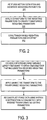
FIG. 2 is a flow diagram of one embodiment of an encoding process. -
FIG. 3 is a flow diagram of one embodiment of a decoding process. -
Figure 4 illustrates a tree with parent-child relationships for encoding of bi-prediction motion information. -
Figure 5 illustrates another tree with node information that may be encoded.. -
Figure 6 is a block diagram of one embodiment of an encoder. -
Figure 7 is a block diagram of one embodiment of a decoder. -
Figure 8 is an example of the relationship between the representation and the true value of the weighting parameter. -
Figure 9 illustrates one embodiment of a flow diagram for a process of using global and local weighting jointly. -
Figure 10 illustrates a transform process of the weighting parameters for coding frames using biprediction. -
Figure 11 illustrates the process for weighting parameters for the multi-hypothesis case. -
Figure 12 illustrates the transform process of the weighting parameters for biprediction with controlled fidelity. -
Figure 13 is a block diagram of an exemplary computer system that may perform one or more of the operations described herein. - An efficient coding scheme for coding weighting parameters within bi-predicted (or multi-predicted) partitions of a video coding architecture is disclosed. This scheme improves performance of the video coding system and can be used to handle local brightness variations. The coding scheme includes a transform process between pairs of weighting parameters associated with each reference for each block that is being subjected to motion compensated prediction. The transform process causes a transform to be applied to the weighting parameters. In one embodiment, the transformed weighting parameters are signaled for every block using a prediction method and are coded using a zero tree coding structure. This reduces the overhead required for coding these parameters. While the methods described herein are primarily aimed at bi-predictive partitions. Some of the concepts could also apply to uni-predicted partitions.
- In one embodiment, the interactions between uni-predicted and bi-predicted partitions are used to further improve efficiency. Special consideration is also made for bi-predictive pictures or slices, where a block may be predicted from a different list or both lists.
- In one embodiment, the coding scheme is further extended by combining and considering both global and local weighting parameters. Additional weighting parameters transmitted at the sequence, picture, or slice level are also optionally considered.
- In another embodiment, the variable granularity dynamic range of such parameters is also taken into account. These weighting parameters are finely adjustable, which provides additional benefits in terms of coding efficiency.
- In the following description, numerous details are set forth to provide a more thorough explanation of the present invention. It will be apparent, however, to one skilled in the art, that the present invention may be practiced without these specific details. In other instances, well-known structures and devices are shown in block diagram form, rather than in detail, in order to avoid obscuring the present invention.
- Some portions of the detailed descriptions which follow are presented in terms of algorithms and symbolic representations of operations on data bits within a computer memory. These algorithmic descriptions and representations are the means used by those skilled in the data processing arts to most effectively convey the substance of their work to others skilled in the art. An algorithm is here, and generally, conceived to be a self-consistent sequence of steps leading to a desired result. The steps are those requiring physical manipulations of physical quantities. Usually, though not necessarily, these quantities take the form of electrical or magnetic signals capable of being stored, transferred, combined, compared, and otherwise manipulated. It has proven convenient at times, principally for reasons of common usage, to refer to these signals as bits, values, elements, symbols, characters, terms, numbers, or the like.
- It should be borne in mind, however, that all of these and similar terms are to be associated with the appropriate physical quantities and are merely convenient labels applied to these quantities. Unless specifically stated otherwise as apparent from the following discussion, it is appreciated that throughout the description, discussions utilizing terms such as "processing" or "computing" or "calculating" or "determining" or "displaying" or the like, refer to the action and processes of a computer system, or similar electronic computing device, that manipulates and transforms data represented as physical (electronic) quantities within the computer system's registers and memories into other data similarly represented as physical quantities within the computer system memories or registers or other such information storage, transmission or display devices.
- The present invention also relates to apparatus for performing the operations herein. This apparatus may be specially constructed for the required purposes, or it may comprise a general purpose computer selectively activated or reconfigured by a computer program stored in the computer. Such a computer program may be stored in a computer readable storage medium, such as, but is not limited to, any type of disk including floppy disks, optical disks, CD-ROMs, and magnetic-optical disks, read-only memories (ROMs), random access memories (RAMs), EPROMs, EEPROMs, magnetic or optical cards, or any type of media suitable for storing electronic instructions, and each coupled to a computer system bus.
- The algorithms and displays presented herein are not inherently related to any particular computer or other apparatus. Various general purpose systems may be used with programs in accordance with the teachings herein, or it may prove convenient to construct more specialized apparatus to perform the required method steps. The required structure for a variety of these systems will appear from the description below. In addition, the present invention is not described with reference to any particular programming language. It will be appreciated that a variety of programming languages may be used to implement the teachings of the invention as described herein.
- A machine-readable medium includes any mechanism for storing or transmitting information in a form readable by a machine (e.g., a computer). For example, a machine-readable medium includes read only memory ("ROM"); random access memory ("RAM"); magnetic disk storage media; optical storage media; flash memory devices; electrical, optical, acoustical or other form of propagated signals (e.g., carrier waves, infrared signals, digital signals, etc.); etc.
- Embodiments of the present invention include a coding scheme that uses motion compensation that includes weighted prediction. The weighting parameters associated with a prediction are transformed and then coded with the offset associated with the prediction. The decoding process is a reverse of the encoding process.
-
Figure 2 is a flow diagram of one embodiment of an encoding process. The process is performed by processing logic that may comprise hardware (circuitry, dedicated logic, etc.), software (such as is run on a general purpose computer system or a dedicated machine), or a combination of both. - Referring to
Figure 2 , the process begins by processing logic generating weighting parameters for multi-hypothesis partitions (e.g., bi-predictive partitions) as part of performing motion estimation (processing block 201). In one embodiment, the weighting parameters comprise at least one pair of a set of weighting parameters for each partition (block) of a frame being encoded. The weights for multiple pairs of transformed weighting parameters sum to a constant. In one embodiment, different weighting factors for at least two partitions of the frame are used. In one embodiment, the weighting parameters compensate for local brightness variations. - In one embodiment, the weighted prediction parameters have variable fidelity levels. The variable fidelity levels are either predefined or signaled as part of a bitstream that includes an encoded representation of the transformed weighting parameters. In one embodiment, one group of weighting parameters have a higher fidelity than those of another group of weighting parameters.
- Next, processing logic applies a transform to the weighting parameters to create transformed weighting parameters (processing block 202). In one embodiment, transforming the weighting parameters comprises applying a transform to at least two weighting parameters associated with each reference. In one embodiment, transforming the weighting parameters comprises applying a transform that satisfies the following:


- After applying a transform to the weighting parameters, processing logic codes transformed weighting parameters and an offset (processing block 203). In one embodiment, the transformed weighting parameters are coded with at least one offset using variable length encoding. The variable length encoding may use a zero tree coding structure. Variable length encoding may comprise Huffman coding or arithmetic coding.
- In one embodiment, coding the transformed weighting parameters comprises differentially coding using predictions based on one of a group consisting of transformed coefficients of neighboring partitions or predetermined weighting parameters. The predetermined weighting parameter are used when no neighboring partition exists for a prediction. The predetermined weighting parameters may be default weighting parameters or globally transmitted weighting parameters.
-
Figure 3 is a flow diagram of one embodiment of a decoding process. In one embodiment, such a decoding process is used to decode information encoded as part of the encoding process ofFigure 2 . The process is performed by processing logic that may comprise hardware (circuitry, dedicated logic, etc.), software (such as is run on a general purpose computer system or a dedicated machine), or a combination of both. - Referring to
Figure 3 , the process begins with processing logic decoding a bitstream using variable length decoding to obtain decoded data that includes transformed weighting parameters for multi-hypothesis partitions (e.g., bi-predictive partitions) (processing block 301). Variable length decoding may comprise Huffman coding or arithmetic coding. - After variable length decoding, processing logic applies an inverse transform to the transformed weighting parameters (processing block 302). In one embodiment, the inverse transformed weighting parameters comprise at least two weighting parameters associated with a reference.
- Then, processing logic reconstructs frame data using motion compensation in conjunction with inverse transformed weighting parameters (processing block 303).
- Weighted prediction is useful for encoding video data that comprises fades, cross-fades/dissolves, and simple brightness variations such as flashes, shading changes etc. Bi-prediction (and multi-hypothesis prediction in general) on the other hand makes the assumption that by combining multiple predictions using simple weighting mechanisms, one may generate a better prediction for a given signal. Conventional bi-prediction tends to use equal weights (i.e. ½) for all predictions. In one embodiment, one signal is more correlated than another, for example due to temporal distance or quantization or other noise introduced/existing within each signal. To perform weighted bi-prediction for a sample I(x, y, t) at position (x, y) at time t is performed, the following may be used:


- The above relationship between the two bi-predictive weights holds true in most cases, i.e. for conventional content without the presence of brightness variations or cross fades.
- In one embodiment, instead of using parameters weight0 and weight1, the N-bit quantized parameters wQ0 and wQ1 are used. In one embodiment, N is 6 bits. Using substitution, equation 5 above then becomes equal to:

- Then two new parameters, namely the transformed quantized parameters B_wQ0 and B_wQ1, and their relationship to the quantized parameter are as follows:


- Considering that the relation in equation 6 may hold for a majority of blocks/partitions, in one embodiment, B_wQ0 may be further modified to


- The parameters B_wQ0 and B_wQ1 are coded as is. In another embodiment, the parameters B_wQ0 and B_wQ1 are differentially coded by considering the values of B_wQ0 and B_wQ1 from neighboring bi-predicted partitions. If no such partitions exist, then these parameters could be predicted using default values dB_wQ0 and dB_wQ1 (e.g., both values could be set to 0).
-
Figure 10 illustrates a transform process of the weighting parameters for coding frames using bi-prediction. Referring toFigure 10 , transform 1001 receives the quantized weighting parameters wQ0 and wQ1 and produces transformed weighting parameters B_wQ0 and B_wQ1, respectively. These transformed weighting parameters are variable length encoded usingvariable length encoder 1002 along with the offset. Thereafter, the encoded weighting parameters are sent as part of the bitstream to a decoder. Thevariable length decoder 1103 decodes the bitstream and produces the transformed weighting parameters B_wQ0 and B_wQ1, along with the offset.Inverse transform 1004 inverse transforms the transformed weighting parameters to produce the quantized version of the weighting parameters wQ0 and wQ1. Weighting parameter wQ0 is multiplied by a motion -compensated sample x0 bymultiplier 1006 to produce an output which is input intoadder 1007. Weighting parameter wQ1 is multiplied by a motion-compensated sample x1 usingmultiplier 1005. The result frommultiplier 1005 is added to the output ofmultiplier 1006 and to 2N-1 usingadder 1007. The output ofadder 1007 is divided by 2N bydivider 1008. The result of the division is added to the offset usingadder 1009 to produce a predicted sample x'. - Note that the present invention is not limited to the bi-prediction case; it is equally applicable to the multi-hypothesis case where M different hypothesis are used. By again making the assumption that the most likely relationship between the M hypothesis weights is of the form


-
Figure 11 illustrates the process for weighting parameters for the multi-hypothesis case. Referring toFigure 11 , the same arrangement as shown inFigure 10 is shown inFigure 11 with the difference that sets of two or more weighting parameters are transformed bytransform 1101 andvariable length encoder 1102 encodes sets of quantized weighting parameters along with one offset for each set With respect to decoding,variable length decoder 1103 decodes the bitstream to produce sets of transformed weighting parameters. Each set of transformed weighting parameters is inverse transformed by aninverse transform 1104, the output of which are a combined to produce a predicted sample x' in the same way as is done inFigure 10 .Adder 1107 adds the results of all multiplications for all of the quantized weighting parameters. - In general, the same picture or slice may have a combination of both bi-predicted and uni-predicted partitions. In particular, it is possible for a bi-predicted partition to have a uni-predicted neighbor using either list0 or list1 prediction, or even a uni-predicted partition using listX (where X could be 0 or 1) having neighbors using a different list. Although motion vectors within a bi-predicted partition could still be correlated with motion vectors of a uni-predicted partition, this is less likely to be the case for motion vectors of different lists, but also of weighting parameters using different number of hypotheses (i.e. weights from bi-predicted partitions may have little relationship with weights from uni-predicted partitions, while a weight and motion vector from a uni-predicted
partition using list 0, may have little relationship with these parameters from another partition using list 1). In one embodiment, all weights from a given prediction mode (list0, list1, and bi-predicted) are restricted to be only predicted from adjacent partitions in the same mode. In one embodiment, if the current partition is a bi-predicted partition, and all R neighbors (Neigh0, Neigh1,... Neigh R ) are also bi-predicted, then a weighting parameter B_wQk is predicted as:
- In alternative embodiments, a function such as the mean, consideration of only the top or left neighbors based on the reference frame they use or/and a predefined cost, etc. However, if NeighJ uses a different prediction type, then it may be excluded from this prediction process. In one embodiment, if no predictions are available, then default values, as previously discussed could be used as a predictor.
- In one embodiment, after prediction, zero tree coding is employed to further efficiently encode the weighting parameters, and in general the motion parameters for a block.
Figures 4 and5 represent two possible trees with the node information that may be encoded . Referring toFigure 4 , an example parent-child relationship for encoding of bi-prediction motion information is shown. In this example, nodes are segmented based on lists, with the horizontal and vertical motion vector displacement difference for ListO having a common parent node and the horizontal and vertical motion vector displacement difference for List1 having a common parent node. InFigure 5 , motion is segmented based on motion vector component. In this case, the horizontal motion vector displacement difference for both ListO and List1 have a common parent node, while the vertical motion vector displacement difference for both ListO and List1 have a common parent mode. - The trees described in
Figure 4 and5 containing both node type data and leaf indices data may be encoded (and subsequently decoded) using tree coding (e.g., zero tree coding) as described inU.S. Patent Application No. 11/172,052 - Default values for a given prediction type, however, do not have to be fixed. In one embodiment, a set of global/default parameters are used and coded such as the ones used by the H.264 explicit mode, or alternatively derive these parameters using a mechanism similar to that of the H.264 implicit mode. The method or parameters could be signaled at the picture or slice level.
-
Figure 9 is a flow diagram of one embodiment for a process of using global and local weighting jointly. The process is performed by processing logic that may comprise hardware (circuitry, dedicated logic, etc.), software (such as is run on a general purpose computer system or a dedicated machine), or a combination of both. - Referring to
Figure 9 , the process begins by setting default weighting parameters (processing block 901). In such a case, there are default scaling and offset parameters for ListO, List1, and Bipred. For ListO, the default weighting parameters are {DScaleL0, DOffsetL0}. For List1, the weighting parameters are {DScaleL1, DOffsetL1}. For bi-prediction, the default weighting parameters are {DScaleBi_L0, DScaleBi_L1,DOffset}. - Then the process continues for each block in the frame, where processing logic tests whether the block is a bi-prediction block (processing block 903). If so, processing logic transitions to processing block 904 where the processing logic tests whether there are any available bi-prediction predictors. If there are, processing logic computes the weighting parameter predictors using neighbors using a function fbipred(Neigh0.... Neigh1) (processing block 905) and processing continues to
processing block 914. If there are no available bi-prediction predictors, processing logic sets the weighting parameters to the default {DScaleBi_L0, DScaleBi_L1,DOffset} (processing block 906) and the processing transitions toprocessing block 914. - If the block in the frame is not undergoing bi-prediction, processing transitions to processing block 907 where processing logic tests whether the block list is List0. If it is, processing logic transitions to processing block 908 where the processing logic tests whether there are any available List0 prediction predictors. If there are, processing logic computes the weighting parameter predictors using neighbors fL0(Neigh0. ... Neigh1) (processing block 909) and processing continues to
processing block 914. If there are no available ListO predictors, processing logic sets the weighting parameters to the default values {DScaleL0, DOffsetL0} (processing block 910) and the processing transitions toprocessing block 914. - If the block isn't undergoing prediction using List0, processing transitions to processing block 911 where the processing logic tests whether there are any available List1 prediction predictors. If there are, processing logic computes the weighting parameter predictors using neighbors fL0(Neigh0....Neigh1) (processing block 912) and processing continues to
processing block 914. If there are no available List1 predictors, processing logic sets the weighting parameters to the default values {DScaleL1, DOffsetL1} (processing block 913) and the processing transitions toprocessing block 914. - At
processing block 914, processing logic decodes the weighting parameters. Thereafter, the weighting parameters predictors are added to the weighting parameters (processing block 915). The process then repeats for each block in the frame, and when each block in the frame has been processed, the process ends. - Based on the discussion above, separate default weights for bi-predicted and uni-predicted partitions can be used, while such parameters could be estimated using similar methods as presented in Kamikura, et al., "Global Brightness-Variation Compensation for Video Coding," IEEE Trans on CSVT, vol. 8, pp. 988-1000, Dec. 1998 and J. Boyce, "Weighted prediction in the H.264/MPEG4 AVC video coding standard", ISCAS, pp. 789-792, May 2004. Table 1 shows an example prediction weight table syntax that could be used for this purpose. It could be observed that in this table, global weights could be signaled separately for uni-predicted and bi-predicted regions.
- Furthermore, bi-predicted weights could have different dynamic range, while the parameters luma_bipred_weight_type and chroma_bipred_weight_type are used to control the method that is to be used for deriving the weights. More specifically for luma, if luma_bipred_weight__type is set to 0, then the default ½ weight is used. If 1, then implicit mode is used, while if 2, the uniprediction weights are used instead as is currently done in H.264 explicit mode. Finally, if 3, weighting parameters are transmitted explicitly within this header.
Table 1 Proposed Prediction Weight Table Syntax pred_weight_table() { C Descriptor //! Dynamic range of unipred weighted parameters luma_log2_weight_denom 2 ue(v) chroma_log2_weight_denom 2 ue(v) //! Signal Uni-pred weigths for list0 for(i = 0; i <= num_ref_idx_l0_active_minus1; i++) { luma_weight_10_flag 2 u(1) if( luma_weight_l0_flag) { luma_weight_l0[i] 2 se(v) luma_offset_l0[i] 2 se(v) } chroma_weight_l0_flag 2 u(1) if( chroma_weight_1l0_flag) for(j =0; j < 2; j++) { chroma_weight_l0[i][j] 2 se(v) chroma_offset_l0[i][j] 2 se(v) } } if( slice_type = = B) { use separate bipred weights 2 u(1) //! Signal Uni-pred weigths for list1 for(I = 0; i <= num_ref_idx_l1_active_minus1; i++) { luma_weight_l1_flag 2 u(1) if( luma_weight_l1_flag) { luma_weight_l1[i] 2 se(v) luma_offset_l1[i] 2 se(v) } chroma_weight_l1_flag 2 u(1) if( chroma_weight_l1_flag) for(j = 0; j < 2; j++ ) { 2 se(v) chroma_weight_l1[i][j] chroma_offset_l1[i][j] 2 se(v) } } //! Signal bi-predictive weights if required if (use_separate_bipred_weights) { //! Dynamic range of bipred weighted parameters luma_bipred_log2_weight_denom 2 ue(v) chroma_bipred_log2_weight_denom 2 ue(v) for(j = 0; j <= num_ref_idx_l0_active_minus1; j++) { luma_bipred_weight_type 2 ue(v) chroma_bipred_weight_type 2 ue(v) for(i = 0; i <= num_ref_idx_l1_active_minus1; i++) { if (luma_bipred_weight_type == 3) { luma_bipred_weight_l0[j][I] 2 se(v) luma_bipred_weight_l1[j][I] 2 se(v) luma bipred offset [j][i]] 2 se(v) } if (chroma_bipred_weight_type == 3) for( k = 0; k < 2; k++) { chroma_bipred_weight_l0[j][i][k] 2 se(v) chroma _bipred_weight_l1[j][i][k] 2 se(v) chroma _bipred_offset[j][i][k] 2 se(v) } } } } } } - Although the fidelity of the weighting and offset parameters could be fixed, i.e. a weighting parameter is uniformly quantized to N bits, non uniform quantization may instead be more efficient and appropriate to better handle different variations within a frame. In one embodiment, a finer fidelity is used for smaller weighting or offset parameters, whereas fidelity is increased for larger parameters.
- In general, encoding a parameter qw k that provides a mapping to the weighting parameters B_wQk,wQk, or even possibly to the differential value dB_wQk is contemplated, using an equation of the form:


- The function represented by equation 17 (or the more generic equation 18) allows for increased flexibility in terms of representing the fidelity of the weighting parameters. Note also that the operation a · x could indicate not only a multiply, but also an integer or floating point divide (i.e. assume that a is less than 1).
Figure 8 is an example of the relationship between the representation and the true value of the weighting parameter. - In one embodiment, the parameters are determined by performing a pre-analysis of the frame or sequence, generating the distribution of the weighting parameters, and approximating the distribution with g(x) (i.e. using a polynomial approximation).
-
Figure 12 illustrates the transform process of the weighting parameters for bi-prediction with controlled fidelity. Referring toFigure 12 , the process is the same as inFigure 10 , with the exception that each of the transformed weighting parameters output fromtransform 1001 isn't input directly into variable-length encoder 1002, along with the offset. Instead, they are input into functions, the output of which are input tovariable length encoder 1002. More specifically, transform weighting parameter B_wQ0 is input into function g0(x) to produce x0. More specifically, transform weighting parameter B_wQ1 is input into function g1(x) to produce x1 (1202). The offset is also subjected to function go(x) to produce x2 (1203). - Similarly, the output of
decoder 1003 which are x0, x1 and x2, are input intofunctions 


Figure 10 . -
Figure 6 is a block diagram of one embodiment of an encoder. In one embodiment the encoder first divides the incoming bitstream into rectangular arrays, referred to as macroblocks. For each macroblock, the encoder then chooses whether to use intra-frame or inter-frame coding. Intra-frame coding uses only the information contained in the current video frame and produces a compressed result referred to as an I-frame. Intra-frame coding can use information of one or more other frames, occurring before or after the current frame. Compressed results that only use data from previous frames are called P-frames, while those that use data from both before and after the current frame are called B-frames. - Referring to
Figure 6 ,video 601 is input into the encoder. In the case of encoding a frame without motion compensation, frames of video are input intoDCT 603.DCT 603 performs a 2D discrete cosign transform (DCT) to create DCT coefficients. The coefficients are quantized byquantizer 604. In one embodiment, the quantization performed byquantizer 604 is weighted by scaler. In one embodiment, the quantizer scaler parameter QP takes values from 1 to 31. The QP value can be modified in both picture and macroblock levels. - Thereafter, the quantized coefficients undergo variable length encoding at
VLC 605, which generatesbitstream 620. In one embodiment,VLC 605 performs entropy coding by using Huffman coding or arithmetic coding. - Note that, in one embodiment, prior to
VLC 605, reordering may be performed in which quantized DCT coefficients are zigzag scanned so that a 2D array of coefficients is converted into a 1D array of coefficients in a manner well-known in the art. This may be followed by run length encoding in which the array of reordered quantized coefficients corresponding to each block is encoded to better represent zero coefficients. In such a case, each nonzero coefficient is encoded as a triplet (last, run, level), where "last" indicates whether this is the final nonzero coefficient in the block, "run" signals thepreceeding 0 coefficients and "level" indicates the coefficients sign and magnitude. - A copy of the frames may be saved for use as a reference frame. This is particularly the case of I or P frames. To that end, the quantized coefficients output from
quantizer 604 are inverse quantized byinverse quantizer 606. An inverse DCT transform is applied to the inverse quantizedcoefficients using IDCT 607. The resulting frame data is added to a motion compensated predication from motion compensation (MC)unit 609 in the case of a P frame and then the resulting frame is filtered usingloop filter 612 and stored inframe buffer 611 for use as a reference frame. In the case of I frames, the data output fromIDCT 607 is not added to a motion compensation prediction fromMC unit 609 and is filtered usingloop filter 612 and stored inframe buffer 611. - In the case of a P frame, the P frame is coded with interprediction from previous a I or P frame, which is referred to commonly in the art as the reference frame. In this case, the interprediction is performed by motion estimation (ME) block 610 and
motion compensation unit 609. In this case, using the reference frame fromframe store 611 and theinput video 601,motion estimation unit 610 searches for a location of a region in the reference frame that best matched the current macro block in the current frame. As discussed above, this includes not only determining a displacement, but also determining weighting parameters (WP) and an offset. The displacement between the current macroblock and the compensation region in the reference frame, along with the weighting parameters and the offset is called the motion vector. The motion vectors formotion estimation unit 610 are sent tomotion compensation unit 609. Atmotion compensation unit 609, the prediction is subtracted from the current macroblock to produce a residuemacroblock using subtractor 602. The residue is then encoded usingDCT 603,quantizer 604 andVLC 605 as described above. -
Motion estimation unit 610 outputs the weighting parameters toVLC 605 forvariable length encoding 605. The output ofVLC 605 isbitstream 620. -
Figure 7 is a block diagram of one embodiment of a decoder. Referring toFigure 7 ,bitstream 701 is received byvariable length decoder 702 which performs variable length decoding. The output of variable length decoding is sent toinverse quantizer 703 which performs an inverse quantization operation that is the opposite of the quantization performed byquantizer 604. The output ofinverse quantizer 703 comprise coefficients that are inverse DCT transformed byIDCT 704 to produce image data. In the case of I frames, the output ofIDCT 704 is simply filtered byloop filter 721, stored inframe buffer 722 and eventually output asoutput 760. In the case of P frames, the image data output fromIDCT 704 is added to the prediction frommotion compensation unit 710 usingadder 705.Motion compensation unit 710 uses the output fromvariable length decoder 722, which includes the weighting parameters discussed above, as well as reference frames fromframe buffer 722. The resulting image data output fromadder 705 is filtered usingloop filter 721 and stored inframe buffer 722 for eventual output as part ofoutput 760. - Thus, as set forth above, embodiments of the present invention allows improved representation of weighting parameters for bi-predictive partitions and improved coding efficiency (i.e. in terms of increased PSNR for a given bitrate) in the presence of brightness variations, or/and cross fades.
-
Figure 13 is a block diagram of an exemplary computer system that may perform one or more of the operations described herein. Referring toFigure 13 ,computer system 1300 may comprise an exemplary client or server computer system.Computer system 1300 comprises a communication mechanism or bus 1311 for communicating information, and aprocessor 1312 coupled with bus 1311 for processing information.Processor 1312 includes a microprocessor, but is not limited to a microprocessor, such as, for example, Pentium™, PowerPC™, Alpha™, etc. -
System 1300 further comprises a random access memory (RAM), or other dynamic storage device 1304 (referred to as main memory) coupled to bus 1311 for storing information and instructions to be executed byprocessor 1312.Main memory 1304 also may be used for storing temporary variables or other intermediate information during execution of instructions byprocessor 1312. -
Computer system 1300 also comprises a read only memory (ROM) and/or otherstatic storage device 1306 coupled to bus 1311 for storing static information and instructions forprocessor 1312, and adata storage device 1307, such as a magnetic disk or optical disk and its corresponding disk drive.Data storage device 1307 is coupled to bus 1311 for storing information and instructions. -
Computer system 1300 may further be coupled to adisplay device 1321, such as a cathode ray tube (CRT) or liquid crystal display (LCD), coupled to bus 1311 for displaying information to a computer user. Analphanumeric input device 1322, including alphanumeric and other keys, may also be coupled to bus 1311 for communicating information and command selections toprocessor 1312. An additional user input device iscursor control 1323, such as a mouse, trackball, trackpad, stylus, or cursor direction keys, coupled to bus 1311 for communicating direction information and command selections toprocessor 1312, and for controlling cursor movement ondisplay 1321. - Another device that may be coupled to bus 1311 is
hard copy device 1324, which may be used for marking information on a medium such as paper, film, or similar types of media. Another device that may be coupled to bus 1311 is a wired/wireless communication capability 1325 to communication to a phone or handheld palm device. - Note that any or all of the components of
system 1300 and associated hardware may be used in the present invention. However, it can be appreciated that other configurations of the computer system may include some or all of the devices.
Claims (11)
- A video encoding method comprising:for an input block of image data performing motion estimation to produce M motion vectors and to generate M original weighting parameters wQi for i = 0 to M - 1 for multi-hypothesis partitions, wherein M different hypotheses are used for each block that is being subjected to motion compensated prediction and wherein each of the multi-hypothesis partitions corresponds to a block belonging to one of one or more reference frames;computing the sum of all of the original weighting parameters, wherein said sum is equal to a constant;transforming said original weighting parameters wQi to transformed weighting parameters B_wQk for k = 0 to M - 1, wherein the first transformed weighting parameter B_wQ0 is equal to said sum of all the original weighting parameters and wherein each remaining transformed weighting parameter B_wQk for k = 1,... M - 1 is equal to wQk-1 minus said sum of all of the original weighting parameters divided by the number of original weighting parameters M;performing motion compensation to generate a prediction using said M motion vectors and said M original weighting parameters;producing a residual by subtracting said prediction from said input block of image data;transforming said residual using a discrete cosine transform to create a 2-D array of transformed coefficients;quantizing said transformed coefficients; andvariable length coding said transformed weighting parameters and said quantized transformed coefficients to generate a bitstream (620).
- The method defined in claim 1 further comprising coding offsets with the transformed weighting parameters.
- The method defined in claim 1 wherein motion compensated prediction uses different weighting parameters for at least two partitions of the frame.
- The method defined in claim 1 wherein the multi-hypothesis partitions comprise bi-predictive partitions.
- The method defined in claim 2 wherein transformed weighting parameters and offsets are coded using variable length encoding.
- The method defined in claim 1 wherein coding the transformed weighting parameters comprises differentially coding using predictions based on one of a group consisting of transformed coefficients of neighboring partitions or predetermined weighting parameters.
- The method defined in claim 6 wherein weighting parameters have variable fidelities.
- A video encoder comprising:a motion estimation unit (610) to generate M original weighting parameters wQi for i = 0 to M - 1 for multi-hypothesis partitions wherein M different hypotheses are used for each block that is being subjected to motion compensation prediction and wherein each of the multi-hypothesis partitions corresponds to a block belonging to one of one or more reference frames;a motion compensation unit (609) to generate a prediction using M motion vectors produced by the motion estimation unit and said M original weighting parameters;a first transform unit (1001) to compute the sum of all of the original weighting parameters into transformed weighting parameters including transforming said original weighting parameters wQi to transformed weighting parameters B_wQk for k = 0 to M - 1, wherein the first transformed weighting parameter B_wQ0 is equal to said sum of all the original weighting parameters and wherein each remaining transformed weighting parameter B_wQk for k = 1,... M - 1 is equal to wQk-1 minus said sum of all of the original weighting parameters divided by the number of original weighting parameters M, wherein said sum is equal to a constant;a subtractor (602) to subtract said prediction from the input block of image data to create a residual;a second transform unit (603) to transform said residual using a discrete cosine transform to create a 2-D array of transformed coefficients;a quantizer (604) to quantize said transformed coefficients; anda variable length coder (605, 1002, 1102) to code said transformed weighting parameters and said quantized transformed coefficients to generate a bitstream (620).
- An article of manufacture comprising one or more recordable media storing instructions thereon which, when executed by a computer, cause the computer to perform a video encoding method comprising:for an input block of image data performing motion estimation to produce M motion vectors and to generate M original weighting parameters wQi for i = 0 to M - 1 for multi-hypothesis partitions wherein M different hypotheses are used for each block that is being subjected to motion compensation prediction and wherein each of the multi-hypothesis partitions corresponds to a block belonging to one of one or more reference frames;computing the sum of all of the original weighting parameters, wherein said sum is equal to a constant;transforming said original weighting parameters wQi to transformed weighting parameters B_wQk for k = 0 to M - 1, wherein the first transformed weighting parameter B_wQ0 is equal to said sum of all the original weighting parameters and wherein each remaining transformed weighting parameter B_wQk for k = 1,... M - 1 is equal to wQk-1 minus said sum of all of the original weighting parameters divided by the number of original weighting parameters M;performing motion compensation to generate a prediction using said M motion vectors and said M original weighting parameters;producing a residual by subtracting said prediction from said input block of image data;transforming said residual using a discrete cosine transform to create a 2-D array of transformed coefficients;quantizing said transformed coefficients; andvariable length coding said transformed weighting parameters and said quantized transformed coefficients to generate a bitstream (620).
- A video decoding method comprising:decoding a bitstream using variable length decoding to obtain decoded data that includes M motion vectors and transformed weighting parameters B_wQk for k = 0 to M - 1 for multi-hypothesis partitions wherein M different hypotheses have been used for each block that has been subjected to motion compensation prediction, wherein each of the multi-hypothesis partitions corresponds to a block belonging to one of one or more reference frames;applying an inverse quantization operation on a portion of the decoded data to produce coefficients;applying a first inverse transform to the coefficients to produce image data;applying a second inverse transform to the transformed weighting parameters B_wQk for k = 0 to M - 1 to produce M original weighting parameters wQi for i = 0 to M - 1, wherein wQk equals toB_wQ0 divided by the number of original weighting parameters M plus B_WQk+1 for k = 1,... M - 2 and wherein wQM-1 equals to B_wQ0 minus the sum of wQi for i = 0 to M - 2, and wherein the sum of the original weighting parameters is equal to a constant; andapplying motion compensation to generate a prediction using said M motion vectors and said M original weighting parameters; andadding the prediction to the image data to reconstruct frame data .
- A video decoder comprising:a variable length decoder (702, 1103) to decode a bitstream (701) using variable length decoding to obtain decoded data that includes M motion vectors and transformed weighting parameters B_wQk for k = 0 to M - 1 transformed from M original weighting parameters wQi for i = 0 to M - 1 for multi-hypothesis partitions wherein M different hypotheses have been used for each block that has been subjected to motion compensation prediction, wherein each of the multi-hypothesis partitions corresponds to a block belonging to one of one or more reference frames;an inverse quantizer (703) to perform an inverse quantization operation on a portion of the decoded data to produce coefficients;a first inverse transform unit (704) to apply a first inverse transform to the coefficients to produce image data;a second inverse transform unit (1004, 1104) to apply a second inverse transform to the transformed weighting parameters B_wQk for k = 0 to M - 1 to produce original weighting parameters wQi for i = 0 to M - 1, wherein wQk equals to B_wQ0 divided by the number of original weighting parameters M plus B_wQk+1 for k = 1,... M - 2 and wherein wQM-1 equals to B_wQ0 minus the sum of wQi for i = 0 to M - 2, and wherein the sum of the original weighting parameters is equal to a constant; anda motion compensation unit (710) to generate a prediction using said M motion vectors and said M original weighting parameters; andan adder (705) to add the prediction to the image data to reconstruct frame data.
Applications Claiming Priority (3)
| Application Number | Priority Date | Filing Date | Title |
|---|---|---|---|
| US68526105P | 2005-05-26 | 2005-05-26 | |
| US11/440,604 US8457203B2 (en) | 2005-05-26 | 2006-05-24 | Method and apparatus for coding motion and prediction weighting parameters |
| PCT/US2006/020633 WO2006128072A2 (en) | 2005-05-26 | 2006-05-25 | Method and apparatus for coding motion and prediction weighting parameters |
Publications (2)
| Publication Number | Publication Date |
|---|---|
| EP1891810A2 EP1891810A2 (en) | 2008-02-27 |
| EP1891810B1 true EP1891810B1 (en) | 2020-03-18 |
Family
ID=37462886
Family Applications (1)
| Application Number | Title | Priority Date | Filing Date |
|---|---|---|---|
| EP06771414.7A Active EP1891810B1 (en) | 2005-05-26 | 2006-05-25 | Method and apparatus for coding motion and prediction weighting parameters |
Country Status (5)
| Country | Link |
|---|---|
| US (1) | US8457203B2 (en) |
| EP (1) | EP1891810B1 (en) |
| JP (2) | JP2008541502A (en) |
| CN (1) | CN101176350B (en) |
| WO (1) | WO2006128072A2 (en) |
Families Citing this family (74)
| Publication number | Priority date | Publication date | Assignee | Title |
|---|---|---|---|---|
| EP1985122A1 (en) * | 2006-02-17 | 2008-10-29 | Thomson Licensing | Localized weighted prediction handling video data brightness variations |
| KR100856411B1 (en) * | 2006-12-01 | 2008-09-04 | 삼성전자주식회사 | Method and apparatus for compensating illumination compensation and method and apparatus for encoding moving picture based on illumination compensation, and method and apparatus for encoding moving picture based on illumination compensation |
| GB2444992A (en) * | 2006-12-21 | 2008-06-25 | Tandberg Television Asa | Video encoding using picture division and weighting by luminance difference data |
| JP2008219100A (en) * | 2007-02-28 | 2008-09-18 | Oki Electric Ind Co Ltd | Predictive image generating device, method and program, and image encoding device, method and program |
| KR101408698B1 (en) | 2007-07-31 | 2014-06-18 | 삼성전자주식회사 | Method and apparatus for encoding/decoding image using weighted prediction |
| CN101911705B (en) * | 2007-12-28 | 2012-08-29 | 夏普株式会社 | Moving image encoder and moving image decoder |
| US8254469B2 (en) * | 2008-05-07 | 2012-08-28 | Kiu Sha Management Liability Company | Error concealment for frame loss in multiple description coding |
| WO2012122423A1 (en) | 2011-03-10 | 2012-09-13 | Dolby Laboratories Licensing Corporation | Pre-processing for bitdepth and color format scalable video coding |
| TWI498003B (en) | 2009-02-02 | 2015-08-21 | Thomson Licensing | Method for decoding a stream representative of a sequence of pictures, method for coding a sequence of pictures and coded data structure |
| US8995526B2 (en) * | 2009-07-09 | 2015-03-31 | Qualcomm Incorporated | Different weights for uni-directional prediction and bi-directional prediction in video coding |
| US8711930B2 (en) * | 2009-07-09 | 2014-04-29 | Qualcomm Incorporated | Non-zero rounding and prediction mode selection techniques in video encoding |
| US9161057B2 (en) * | 2009-07-09 | 2015-10-13 | Qualcomm Incorporated | Non-zero rounding and prediction mode selection techniques in video encoding |
| FR2948845A1 (en) * | 2009-07-30 | 2011-02-04 | Thomson Licensing | METHOD FOR DECODING A FLOW REPRESENTATIVE OF AN IMAGE SEQUENCE AND METHOD FOR CODING AN IMAGE SEQUENCE |
| EP2302933A1 (en) * | 2009-09-17 | 2011-03-30 | Mitsubishi Electric R&D Centre Europe B.V. | Weighted motion compensation of video |
| US20110075724A1 (en) * | 2009-09-29 | 2011-03-31 | Qualcomm Incorporated | Encoding parameters with unit sum |
| US9161058B2 (en) * | 2010-03-27 | 2015-10-13 | Texas Instruments Incorporated | Method and system for detecting global brightness change for weighted prediction in video encoding |
| JP5393573B2 (en) * | 2010-04-08 | 2014-01-22 | 株式会社Nttドコモ | Moving picture predictive coding apparatus, moving picture predictive decoding apparatus, moving picture predictive coding method, moving picture predictive decoding method, moving picture predictive coding program, and moving picture predictive decoding program |
| JP5325157B2 (en) * | 2010-04-09 | 2013-10-23 | 株式会社エヌ・ティ・ティ・ドコモ | Moving picture encoding apparatus, moving picture decoding apparatus, moving picture encoding method, moving picture decoding method, moving picture encoding program, and moving picture decoding program |
| US8971400B2 (en) * | 2010-04-14 | 2015-03-03 | Mediatek Inc. | Method for performing hybrid multihypothesis prediction during video coding of a coding unit, and associated apparatus |
| US9118929B2 (en) | 2010-04-14 | 2015-08-25 | Mediatek Inc. | Method for performing hybrid multihypothesis prediction during video coding of a coding unit, and associated apparatus |
| US8908755B2 (en) * | 2010-07-16 | 2014-12-09 | Sony Corporation | Multi-parameter motion for efficient prediction in video compression |
| JP5298140B2 (en) * | 2011-01-12 | 2013-09-25 | 株式会社エヌ・ティ・ティ・ドコモ | Image predictive encoding device, image predictive encoding method, image predictive encoding program, image predictive decoding device, image predictive decoding method, and image predictive decoding program |
| EP2684365A1 (en) * | 2011-03-10 | 2014-01-15 | Dolby Laboratories Licensing Corporation | Bitdepth and color scalable video coding |
| WO2012122426A1 (en) * | 2011-03-10 | 2012-09-13 | Dolby Laboratories Licensing Corporation | Reference processing for bitdepth and color format scalable video coding |
| JPWO2012172668A1 (en) * | 2011-06-15 | 2015-02-23 | 株式会社東芝 | Moving picture encoding method and apparatus, and moving picture decoding method and apparatus |
| WO2012172668A1 (en) * | 2011-06-15 | 2012-12-20 | 株式会社 東芝 | Video encoding method and device, and video decoding method and device |
| KR20120140592A (en) | 2011-06-21 | 2012-12-31 | 한국전자통신연구원 | Method and apparatus for reducing computational complexity of motion compensation and increasing coding efficiency |
| WO2012177052A2 (en) | 2011-06-21 | 2012-12-27 | 한국전자통신연구원 | Inter-prediction method and apparatus for same |
| KR20140034292A (en) * | 2011-07-01 | 2014-03-19 | 모토로라 모빌리티 엘엘씨 | Motion vector prediction design simplification |
| EP2763414B1 (en) * | 2011-09-29 | 2020-09-23 | Sharp Kabushiki Kaisha | Image decoding device and image decoding method for performing bi-prediction to uni-prediction conversion |
| WO2013047805A1 (en) | 2011-09-29 | 2013-04-04 | シャープ株式会社 | Image decoding apparatus, image decoding method and image encoding apparatus |
| SG11201400294SA (en) | 2011-10-17 | 2014-09-26 | Toshiba Kk | Encoding device, decoding device, encoding method, and decoding method |
| JPWO2013057783A1 (en) * | 2011-10-17 | 2015-04-02 | 株式会社東芝 | Encoding method and decoding method |
| WO2013067440A1 (en) | 2011-11-04 | 2013-05-10 | General Instrument Corporation | Motion vector scaling for non-uniform motion vector grid |
| JP5485969B2 (en) * | 2011-11-07 | 2014-05-07 | 株式会社Nttドコモ | Moving picture predictive coding apparatus, moving picture predictive coding method, moving picture predictive coding program, moving picture predictive decoding apparatus, moving picture predictive decoding method, and moving picture predictive decoding program |
| US9756353B2 (en) | 2012-01-09 | 2017-09-05 | Dolby Laboratories Licensing Corporation | Hybrid reference picture reconstruction method for single and multiple layered video coding systems |
| US9420302B2 (en) | 2012-01-24 | 2016-08-16 | Dolby Laboratories Licensing Corporation | Weighted multi-band cross color channel predictor |
| US9172970B1 (en) | 2012-05-29 | 2015-10-27 | Google Inc. | Inter frame candidate selection for a video encoder |
| US11317101B2 (en) | 2012-06-12 | 2022-04-26 | Google Inc. | Inter frame candidate selection for a video encoder |
| KR101624059B1 (en) | 2012-06-27 | 2016-05-24 | 가부시끼가이샤 도시바 | Encoding device and encoding method |
| US9602827B2 (en) | 2012-07-02 | 2017-03-21 | Qualcomm Incorporated | Video parameter set including an offset syntax element |
| US9906786B2 (en) * | 2012-09-07 | 2018-02-27 | Qualcomm Incorporated | Weighted prediction mode for scalable video coding |
| CN102828045B (en) * | 2012-09-07 | 2013-08-21 | 白银有色集团股份有限公司 | Special pulverized coal burner for silver and copper molten pool smelting furnace |
| US9503746B2 (en) | 2012-10-08 | 2016-11-22 | Google Inc. | Determine reference motion vectors |
| US9485515B2 (en) | 2013-08-23 | 2016-11-01 | Google Inc. | Video coding using reference motion vectors |
| US9485508B2 (en) | 2013-04-08 | 2016-11-01 | Qualcomm Incorporated | Non-entropy encoded set of profile, tier, and level syntax structures |
| CN104488271B (en) * | 2013-07-26 | 2019-05-07 | 北京大学深圳研究生院 | A kind of more hypothesis motion compensation process based on P frame |
| JP5702011B2 (en) * | 2014-04-07 | 2015-04-15 | 株式会社東芝 | Encoding method, encoding apparatus, and program |
| JP5869160B2 (en) * | 2015-02-16 | 2016-02-24 | 株式会社東芝 | Decoding method, decoding apparatus, and program |
| JP6088036B2 (en) * | 2015-12-22 | 2017-03-01 | 株式会社東芝 | Decoding method, decoding apparatus, and program |
| RU2638756C2 (en) * | 2016-05-13 | 2017-12-15 | Кабусики Кайся Тосиба | Encoding device, decoding device, encoding method and decoding method |
| CN109496430B (en) * | 2016-05-13 | 2022-06-14 | Vid拓展公司 | System and method for generalized multi-hypothesis prediction for video coding |
| CN106358041B (en) | 2016-08-30 | 2019-05-10 | 北京奇艺世纪科技有限公司 | A kind of interframe prediction encoding method and device |
| CN106230578B (en) * | 2016-09-08 | 2019-09-27 | 哈尔滨工程大学 | A kind of safe arithmetic coding method of binary system of the three-dimensional Lorenz mapping control based on weighting processing |
| JP6235742B2 (en) * | 2017-01-30 | 2017-11-22 | 株式会社東芝 | Electronic device, decoding method and program |
| JP6235745B2 (en) * | 2017-02-23 | 2017-11-22 | 株式会社東芝 | Electronic device, decoding method and program |
| CN106851389A (en) * | 2017-02-24 | 2017-06-13 | 深圳市安拓浦科技有限公司 | The equipment that a kind of use WIFI transmits TV signals |
| US20180332298A1 (en) * | 2017-05-10 | 2018-11-15 | Futurewei Technologies, Inc. | Bidirectional Prediction In Video Compression |
| US10778978B2 (en) * | 2017-08-21 | 2020-09-15 | Qualcomm Incorporated | System and method of cross-component dynamic range adjustment (CC-DRA) in video coding |
| JP6396566B2 (en) * | 2017-10-20 | 2018-09-26 | 株式会社東芝 | Electronic device, encoding method and program |
| US11153602B2 (en) | 2018-01-24 | 2021-10-19 | Vid Scale, Inc. | Generalized bi-prediction for video coding with reduced coding complexity |
| WO2019152283A1 (en) * | 2018-02-02 | 2019-08-08 | Apple Inc. | Techniques of multi-hypothesis motion compensation |
| US11924440B2 (en) * | 2018-02-05 | 2024-03-05 | Apple Inc. | Techniques of multi-hypothesis motion compensation |
| EP3540512B1 (en) * | 2018-03-16 | 2022-04-06 | Qingdao Hisense Laser Display Co., Ltd. | Laser projection apparatus |
| WO2019229683A1 (en) * | 2018-05-31 | 2019-12-05 | Beijing Bytedance Network Technology Co., Ltd. | Concept of interweaved prediction |
| JP2019009792A (en) * | 2018-08-22 | 2019-01-17 | 株式会社東芝 | Encoding method, decoding method and encoded data |
| CN110944181B (en) | 2018-09-23 | 2023-03-10 | 北京字节跳动网络技术有限公司 | Multiple assumptions for affine models |
| WO2020084470A1 (en) | 2018-10-22 | 2020-04-30 | Beijing Bytedance Network Technology Co., Ltd. | Storage of motion parameters with clipping for affine mode |
| CN113454999A (en) | 2019-01-02 | 2021-09-28 | 北京字节跳动网络技术有限公司 | Motion vector derivation between partition modes |
| US11134246B2 (en) * | 2019-01-02 | 2021-09-28 | Shumaker & Sieffert, P.A. | Weighted prediction for video coding |
| CN114731442B (en) * | 2019-09-16 | 2023-12-01 | Lg电子株式会社 | Image encoding/decoding method and apparatus using weighted prediction and method of transmitting bitstream |
| JP6744507B2 (en) * | 2020-01-07 | 2020-08-19 | 株式会社東芝 | Encoding method and decoding method |
| JP7000498B2 (en) * | 2020-05-29 | 2022-01-19 | 株式会社東芝 | Storage device, transmitter and coding method |
| FR3120174A1 (en) * | 2021-02-19 | 2022-08-26 | Orange | Weighted picture prediction, picture coding and decoding using such weighted prediction |
Family Cites Families (13)
| Publication number | Priority date | Publication date | Assignee | Title |
|---|---|---|---|---|
| US5758257A (en) * | 1994-11-29 | 1998-05-26 | Herz; Frederick | System and method for scheduling broadcast of and access to video programs and other data using customer profiles |
| DE60204447T2 (en) * | 2001-02-13 | 2006-04-27 | Koninklijke Philips Electronics N.V. | METHOD OF CODING AND DECODING MOTOR ESTIMATION |
| HK1037462A2 (en) * | 2001-07-20 | 2002-01-04 | Univ City Hong Kong | Image compression |
| JP2004007379A (en) | 2002-04-10 | 2004-01-08 | Toshiba Corp | Method for encoding moving image and method for decoding moving image |
| CA2574127A1 (en) | 2002-01-18 | 2003-07-31 | Kabushiki Kaisha Toshiba | Video encoding method and apparatus and video decoding method and apparatus |
| US7003035B2 (en) * | 2002-01-25 | 2006-02-21 | Microsoft Corporation | Video coding methods and apparatuses |
| CN100352287C (en) | 2002-10-01 | 2007-11-28 | 松下电器产业株式会社 | Picture encoding device, image decoding device and their methods |
| MY139467A (en) * | 2003-01-07 | 2009-10-30 | Thomson Licensing Sa | Mixed inter/intra video coding of macroblock partitions |
| US7809059B2 (en) * | 2003-06-25 | 2010-10-05 | Thomson Licensing | Method and apparatus for weighted prediction estimation using a displaced frame differential |
| US8731054B2 (en) | 2004-05-04 | 2014-05-20 | Qualcomm Incorporated | Method and apparatus for weighted prediction in predictive frames |
| KR100654436B1 (en) * | 2004-07-07 | 2006-12-06 | 삼성전자주식회사 | Method for video encoding and decoding, and video encoder and decoder |
| CN101023673B (en) * | 2004-09-16 | 2011-06-08 | 汤姆逊许可证公司 | Video codec with weighted prediction utilizing local brightness variation |
| US8228994B2 (en) * | 2005-05-20 | 2012-07-24 | Microsoft Corporation | Multi-view video coding based on temporal and view decomposition |
-
2006
- 2006-05-24 US US11/440,604 patent/US8457203B2/en active Active
- 2006-05-25 CN CN200680016666XA patent/CN101176350B/en active Active
- 2006-05-25 JP JP2008508011A patent/JP2008541502A/en active Pending
- 2006-05-25 WO PCT/US2006/020633 patent/WO2006128072A2/en active Application Filing
- 2006-05-25 EP EP06771414.7A patent/EP1891810B1/en active Active
-
2010
- 2010-12-06 JP JP2010271444A patent/JP5086422B2/en active Active
Non-Patent Citations (1)
| Title |
|---|
| None * |
Also Published As
| Publication number | Publication date |
|---|---|
| CN101176350A (en) | 2008-05-07 |
| WO2006128072A3 (en) | 2007-03-01 |
| CN101176350B (en) | 2011-02-23 |
| JP5086422B2 (en) | 2012-11-28 |
| JP2008541502A (en) | 2008-11-20 |
| US8457203B2 (en) | 2013-06-04 |
| EP1891810A2 (en) | 2008-02-27 |
| JP2011091840A (en) | 2011-05-06 |
| WO2006128072A2 (en) | 2006-11-30 |
| US20060268166A1 (en) | 2006-11-30 |
Similar Documents
| Publication | Publication Date | Title |
|---|---|---|
| EP1891810B1 (en) | Method and apparatus for coding motion and prediction weighting parameters | |
| US10687075B2 (en) | Sub-block transform coding of prediction residuals | |
| US8208564B2 (en) | Method and apparatus for video encoding and decoding using adaptive interpolation | |
| EP2290991B1 (en) | Predicting motion vectors for fields of forward-predicted interlaced video frames | |
| US8855202B2 (en) | Flexible range reduction | |
| US9374577B2 (en) | Method and apparatus for selecting a coding mode | |
| EP1999958B1 (en) | Method of reducing computations in intra-prediction mode decision processes in a digital video encoder | |
| US8831087B2 (en) | Efficient prediction mode selection | |
| US10735746B2 (en) | Method and apparatus for motion compensation prediction | |
| US8995526B2 (en) | Different weights for uni-directional prediction and bi-directional prediction in video coding | |
| KR101377883B1 (en) | Non-zero rounding and prediction mode selection techniques in video encoding | |
| US7499495B2 (en) | Extended range motion vectors | |
| US20050013497A1 (en) | Intraframe and interframe interlace coding and decoding | |
| US7577200B2 (en) | Extended range variable length coding/decoding of differential motion vector information | |
| Schwarz et al. | The emerging JVT/H. 26L video coding standard | |
| US20090257496A1 (en) | Estimation of b frame average rate quantization parameter (qp) in a group of pictures (gop) | |
| US20090257488A1 (en) | Estimation of i frame average rate quantization parameter (qp) in a group of pictures (gop) | |
| KR20050122275A (en) | System and method for rate-distortion optimized data partitioning for video coding using parametric rate-distortion model | |
| EP4268460A1 (en) | Temporal filter | |
| Ismaeil | Computation-distortion optimized DCT-based video coding |
Legal Events
| Date | Code | Title | Description |
|---|---|---|---|
| PUAI | Public reference made under article 153(3) epc to a published international application that has entered the european phase |
Free format text: ORIGINAL CODE: 0009012 |
|
| 17P | Request for examination filed |
Effective date: 20070913 |
|
| AK | Designated contracting states |
Kind code of ref document: A2 Designated state(s): AT BE BG CH CY CZ DE DK EE ES FI FR GB GR HU IE IS IT LI LT LU LV MC NL PL PT RO SE SI SK TR |
|
| DAX | Request for extension of the european patent (deleted) | ||
| 17Q | First examination report despatched |
Effective date: 20100201 |
|
| STAA | Information on the status of an ep patent application or granted ep patent |
Free format text: STATUS: EXAMINATION IS IN PROGRESS |
|
| REG | Reference to a national code |
Ref country code: DE Ref legal event code: R079 Ref document number: 602006059225 Country of ref document: DE Free format text: PREVIOUS MAIN CLASS: H04N0007260000 Ipc: H04N0019463000 |
|
| GRAP | Despatch of communication of intention to grant a patent |
Free format text: ORIGINAL CODE: EPIDOSNIGR1 |
|
| STAA | Information on the status of an ep patent application or granted ep patent |
Free format text: STATUS: GRANT OF PATENT IS INTENDED |
|
| RIC1 | Information provided on ipc code assigned before grant |
Ipc: H04N 19/463 20140101AFI20190919BHEP Ipc: H04N 19/61 20140101ALI20190919BHEP Ipc: H04N 19/577 20140101ALI20190919BHEP Ipc: H04N 19/70 20140101ALI20190919BHEP Ipc: H04N 19/587 20140101ALI20190919BHEP |
|
| INTG | Intention to grant announced |
Effective date: 20191011 |
|
| GRAS | Grant fee paid |
Free format text: ORIGINAL CODE: EPIDOSNIGR3 |
|
| GRAA | (expected) grant |
Free format text: ORIGINAL CODE: 0009210 |
|
| STAA | Information on the status of an ep patent application or granted ep patent |
Free format text: STATUS: THE PATENT HAS BEEN GRANTED |
|
| AK | Designated contracting states |
Kind code of ref document: B1 Designated state(s): AT BE BG CH CY CZ DE DK EE ES FI FR GB GR HU IE IS IT LI LT LU LV MC NL PL PT RO SE SI SK TR |
|
| REG | Reference to a national code |
Ref country code: GB Ref legal event code: FG4D |
|
| REG | Reference to a national code |
Ref country code: DE Ref legal event code: R096 Ref document number: 602006059225 Country of ref document: DE |
|
| REG | Reference to a national code |
Ref country code: AT Ref legal event code: REF Ref document number: 1247276 Country of ref document: AT Kind code of ref document: T Effective date: 20200415 Ref country code: IE Ref legal event code: FG4D |
|
| PG25 | Lapsed in a contracting state [announced via postgrant information from national office to epo] |
Ref country code: FI Free format text: LAPSE BECAUSE OF FAILURE TO SUBMIT A TRANSLATION OF THE DESCRIPTION OR TO PAY THE FEE WITHIN THE PRESCRIBED TIME-LIMIT Effective date: 20200318 |
|
| REG | Reference to a national code |
Ref country code: NL Ref legal event code: MP Effective date: 20200318 |
|
| PG25 | Lapsed in a contracting state [announced via postgrant information from national office to epo] |
Ref country code: LV Free format text: LAPSE BECAUSE OF FAILURE TO SUBMIT A TRANSLATION OF THE DESCRIPTION OR TO PAY THE FEE WITHIN THE PRESCRIBED TIME-LIMIT Effective date: 20200318 Ref country code: SE Free format text: LAPSE BECAUSE OF FAILURE TO SUBMIT A TRANSLATION OF THE DESCRIPTION OR TO PAY THE FEE WITHIN THE PRESCRIBED TIME-LIMIT Effective date: 20200318 Ref country code: BG Free format text: LAPSE BECAUSE OF FAILURE TO SUBMIT A TRANSLATION OF THE DESCRIPTION OR TO PAY THE FEE WITHIN THE PRESCRIBED TIME-LIMIT Effective date: 20200618 Ref country code: GR Free format text: LAPSE BECAUSE OF FAILURE TO SUBMIT A TRANSLATION OF THE DESCRIPTION OR TO PAY THE FEE WITHIN THE PRESCRIBED TIME-LIMIT Effective date: 20200619 |
|
| REG | Reference to a national code |
Ref country code: LT Ref legal event code: MG4D |
|
| PG25 | Lapsed in a contracting state [announced via postgrant information from national office to epo] |
Ref country code: NL Free format text: LAPSE BECAUSE OF FAILURE TO SUBMIT A TRANSLATION OF THE DESCRIPTION OR TO PAY THE FEE WITHIN THE PRESCRIBED TIME-LIMIT Effective date: 20200318 |
|
| PG25 | Lapsed in a contracting state [announced via postgrant information from national office to epo] |
Ref country code: EE Free format text: LAPSE BECAUSE OF FAILURE TO SUBMIT A TRANSLATION OF THE DESCRIPTION OR TO PAY THE FEE WITHIN THE PRESCRIBED TIME-LIMIT Effective date: 20200318 Ref country code: LT Free format text: LAPSE BECAUSE OF FAILURE TO SUBMIT A TRANSLATION OF THE DESCRIPTION OR TO PAY THE FEE WITHIN THE PRESCRIBED TIME-LIMIT Effective date: 20200318 Ref country code: PT Free format text: LAPSE BECAUSE OF FAILURE TO SUBMIT A TRANSLATION OF THE DESCRIPTION OR TO PAY THE FEE WITHIN THE PRESCRIBED TIME-LIMIT Effective date: 20200812 Ref country code: SK Free format text: LAPSE BECAUSE OF FAILURE TO SUBMIT A TRANSLATION OF THE DESCRIPTION OR TO PAY THE FEE WITHIN THE PRESCRIBED TIME-LIMIT Effective date: 20200318 Ref country code: IS Free format text: LAPSE BECAUSE OF FAILURE TO SUBMIT A TRANSLATION OF THE DESCRIPTION OR TO PAY THE FEE WITHIN THE PRESCRIBED TIME-LIMIT Effective date: 20200718 Ref country code: CZ Free format text: LAPSE BECAUSE OF FAILURE TO SUBMIT A TRANSLATION OF THE DESCRIPTION OR TO PAY THE FEE WITHIN THE PRESCRIBED TIME-LIMIT Effective date: 20200318 Ref country code: RO Free format text: LAPSE BECAUSE OF FAILURE TO SUBMIT A TRANSLATION OF THE DESCRIPTION OR TO PAY THE FEE WITHIN THE PRESCRIBED TIME-LIMIT Effective date: 20200318 |
|
| REG | Reference to a national code |
Ref country code: AT Ref legal event code: MK05 Ref document number: 1247276 Country of ref document: AT Kind code of ref document: T Effective date: 20200318 |
|
| REG | Reference to a national code |
Ref country code: DE Ref legal event code: R097 Ref document number: 602006059225 Country of ref document: DE |
|
| PLBE | No opposition filed within time limit |
Free format text: ORIGINAL CODE: 0009261 |
|
| STAA | Information on the status of an ep patent application or granted ep patent |
Free format text: STATUS: NO OPPOSITION FILED WITHIN TIME LIMIT |
|
| PG25 | Lapsed in a contracting state [announced via postgrant information from national office to epo] |
Ref country code: CH Free format text: LAPSE BECAUSE OF NON-PAYMENT OF DUE FEES Effective date: 20200531 Ref country code: IT Free format text: LAPSE BECAUSE OF FAILURE TO SUBMIT A TRANSLATION OF THE DESCRIPTION OR TO PAY THE FEE WITHIN THE PRESCRIBED TIME-LIMIT Effective date: 20200318 Ref country code: MC Free format text: LAPSE BECAUSE OF FAILURE TO SUBMIT A TRANSLATION OF THE DESCRIPTION OR TO PAY THE FEE WITHIN THE PRESCRIBED TIME-LIMIT Effective date: 20200318 Ref country code: DK Free format text: LAPSE BECAUSE OF FAILURE TO SUBMIT A TRANSLATION OF THE DESCRIPTION OR TO PAY THE FEE WITHIN THE PRESCRIBED TIME-LIMIT Effective date: 20200318 Ref country code: AT Free format text: LAPSE BECAUSE OF FAILURE TO SUBMIT A TRANSLATION OF THE DESCRIPTION OR TO PAY THE FEE WITHIN THE PRESCRIBED TIME-LIMIT Effective date: 20200318 Ref country code: LI Free format text: LAPSE BECAUSE OF NON-PAYMENT OF DUE FEES Effective date: 20200531 Ref country code: ES Free format text: LAPSE BECAUSE OF FAILURE TO SUBMIT A TRANSLATION OF THE DESCRIPTION OR TO PAY THE FEE WITHIN THE PRESCRIBED TIME-LIMIT Effective date: 20200318 |
|
| 26N | No opposition filed |
Effective date: 20201221 |
|
| PG25 | Lapsed in a contracting state [announced via postgrant information from national office to epo] |
Ref country code: PL Free format text: LAPSE BECAUSE OF FAILURE TO SUBMIT A TRANSLATION OF THE DESCRIPTION OR TO PAY THE FEE WITHIN THE PRESCRIBED TIME-LIMIT Effective date: 20200318 |
|
| REG | Reference to a national code |
Ref country code: BE Ref legal event code: MM Effective date: 20200531 |
|
| PG25 | Lapsed in a contracting state [announced via postgrant information from national office to epo] |
Ref country code: LU Free format text: LAPSE BECAUSE OF NON-PAYMENT OF DUE FEES Effective date: 20200525 |
|
| PG25 | Lapsed in a contracting state [announced via postgrant information from national office to epo] |
Ref country code: IE Free format text: LAPSE BECAUSE OF NON-PAYMENT OF DUE FEES Effective date: 20200525 |
|
| PG25 | Lapsed in a contracting state [announced via postgrant information from national office to epo] |
Ref country code: SI Free format text: LAPSE BECAUSE OF FAILURE TO SUBMIT A TRANSLATION OF THE DESCRIPTION OR TO PAY THE FEE WITHIN THE PRESCRIBED TIME-LIMIT Effective date: 20200318 Ref country code: BE Free format text: LAPSE BECAUSE OF NON-PAYMENT OF DUE FEES Effective date: 20200531 |
|
| PG25 | Lapsed in a contracting state [announced via postgrant information from national office to epo] |
Ref country code: TR Free format text: LAPSE BECAUSE OF FAILURE TO SUBMIT A TRANSLATION OF THE DESCRIPTION OR TO PAY THE FEE WITHIN THE PRESCRIBED TIME-LIMIT Effective date: 20200318 Ref country code: CY Free format text: LAPSE BECAUSE OF FAILURE TO SUBMIT A TRANSLATION OF THE DESCRIPTION OR TO PAY THE FEE WITHIN THE PRESCRIBED TIME-LIMIT Effective date: 20200318 |
|
| P01 | Opt-out of the competence of the unified patent court (upc) registered |
Effective date: 20230510 |
|
| PGFP | Annual fee paid to national office [announced via postgrant information from national office to epo] |
Ref country code: FR Payment date: 20230525 Year of fee payment: 18 Ref country code: DE Payment date: 20230519 Year of fee payment: 18 |
|
| PGFP | Annual fee paid to national office [announced via postgrant information from national office to epo] |
Ref country code: GB Payment date: 20230523 Year of fee payment: 18 |