EP1891472B1 - High sbs threshold optical fiber with aluminium dopant - Google Patents
High sbs threshold optical fiber with aluminium dopant Download PDFInfo
- Publication number
- EP1891472B1 EP1891472B1 EP06844136.9A EP06844136A EP1891472B1 EP 1891472 B1 EP1891472 B1 EP 1891472B1 EP 06844136 A EP06844136 A EP 06844136A EP 1891472 B1 EP1891472 B1 EP 1891472B1
- Authority
- EP
- European Patent Office
- Prior art keywords
- optical
- acoustic
- fiber
- core
- delta
- Prior art date
- Legal status (The legal status is an assumption and is not a legal conclusion. Google has not performed a legal analysis and makes no representation as to the accuracy of the status listed.)
- Expired - Fee Related
Links
Images


Classifications
-
- G—PHYSICS
- G02—OPTICS
- G02B—OPTICAL ELEMENTS, SYSTEMS OR APPARATUS
- G02B6/00—Light guides; Structural details of arrangements comprising light guides and other optical elements, e.g. couplings
- G02B6/02—Optical fibres with cladding with or without a coating
- G02B6/036—Optical fibres with cladding with or without a coating core or cladding comprising multiple layers
- G02B6/03694—Multiple layers differing in properties other than the refractive index, e.g. attenuation, diffusion, stress properties
-
- G—PHYSICS
- G02—OPTICS
- G02B—OPTICAL ELEMENTS, SYSTEMS OR APPARATUS
- G02B6/00—Light guides; Structural details of arrangements comprising light guides and other optical elements, e.g. couplings
- G02B6/02—Optical fibres with cladding with or without a coating
-
- H—ELECTRICITY
- H01—ELECTRIC ELEMENTS
- H01S—DEVICES USING THE PROCESS OF LIGHT AMPLIFICATION BY STIMULATED EMISSION OF RADIATION [LASER] TO AMPLIFY OR GENERATE LIGHT; DEVICES USING STIMULATED EMISSION OF ELECTROMAGNETIC RADIATION IN WAVE RANGES OTHER THAN OPTICAL
- H01S3/00—Lasers, i.e. devices using stimulated emission of electromagnetic radiation in the infrared, visible or ultraviolet wave range
- H01S3/05—Construction or shape of optical resonators; Accommodation of active medium therein; Shape of active medium
- H01S3/06—Construction or shape of active medium
- H01S3/063—Waveguide lasers, i.e. whereby the dimensions of the waveguide are of the order of the light wavelength
- H01S3/067—Fibre lasers
- H01S3/06708—Constructional details of the fibre, e.g. compositions, cross-section, shape or tapering
-
- G—PHYSICS
- G02—OPTICS
- G02B—OPTICAL ELEMENTS, SYSTEMS OR APPARATUS
- G02B6/00—Light guides; Structural details of arrangements comprising light guides and other optical elements, e.g. couplings
- G02B6/02—Optical fibres with cladding with or without a coating
- G02B6/02004—Optical fibres with cladding with or without a coating characterised by the core effective area or mode field radius
- G02B6/02009—Large effective area or mode field radius, e.g. to reduce nonlinear effects in single mode fibres
- G02B6/02014—Effective area greater than 60 square microns in the C band, i.e. 1530-1565 nm
- G02B6/02019—Effective area greater than 90 square microns in the C band, i.e. 1530-1565 nm
-
- G—PHYSICS
- G02—OPTICS
- G02B—OPTICAL ELEMENTS, SYSTEMS OR APPARATUS
- G02B6/00—Light guides; Structural details of arrangements comprising light guides and other optical elements, e.g. couplings
- G02B6/02—Optical fibres with cladding with or without a coating
- G02B6/02214—Optical fibres with cladding with or without a coating tailored to obtain the desired dispersion, e.g. dispersion shifted, dispersion flattened
- G02B6/02219—Characterised by the wavelength dispersion properties in the silica low loss window around 1550 nm, i.e. S, C, L and U bands from 1460-1675 nm
- G02B6/02266—Positive dispersion fibres at 1550 nm
- G02B6/02271—Non-zero dispersion shifted fibres, i.e. having a small positive dispersion at 1550 nm, e.g. ITU-T G.655 dispersion between 1.0 to 10 ps/nm.km for avoiding nonlinear effects
-
- G—PHYSICS
- G02—OPTICS
- G02B—OPTICAL ELEMENTS, SYSTEMS OR APPARATUS
- G02B6/00—Light guides; Structural details of arrangements comprising light guides and other optical elements, e.g. couplings
- G02B6/02—Optical fibres with cladding with or without a coating
- G02B6/02214—Optical fibres with cladding with or without a coating tailored to obtain the desired dispersion, e.g. dispersion shifted, dispersion flattened
- G02B6/02219—Characterised by the wavelength dispersion properties in the silica low loss window around 1550 nm, i.e. S, C, L and U bands from 1460-1675 nm
- G02B6/02276—Dispersion shifted fibres, i.e. zero dispersion at 1550 nm
-
- G—PHYSICS
- G02—OPTICS
- G02B—OPTICAL ELEMENTS, SYSTEMS OR APPARATUS
- G02B6/00—Light guides; Structural details of arrangements comprising light guides and other optical elements, e.g. couplings
- G02B6/02—Optical fibres with cladding with or without a coating
- G02B6/028—Optical fibres with cladding with or without a coating with core or cladding having graded refractive index
- G02B6/0281—Graded index region forming part of the central core segment, e.g. alpha profile, triangular, trapezoidal core
-
- G—PHYSICS
- G02—OPTICS
- G02B—OPTICAL ELEMENTS, SYSTEMS OR APPARATUS
- G02B6/00—Light guides; Structural details of arrangements comprising light guides and other optical elements, e.g. couplings
- G02B6/02—Optical fibres with cladding with or without a coating
- G02B6/036—Optical fibres with cladding with or without a coating core or cladding comprising multiple layers
- G02B6/03616—Optical fibres characterised both by the number of different refractive index layers around the central core segment, i.e. around the innermost high index core layer, and their relative refractive index difference
- G02B6/03638—Optical fibres characterised both by the number of different refractive index layers around the central core segment, i.e. around the innermost high index core layer, and their relative refractive index difference having 3 layers only
- G02B6/03644—Optical fibres characterised both by the number of different refractive index layers around the central core segment, i.e. around the innermost high index core layer, and their relative refractive index difference having 3 layers only arranged - + -
Description
- The present invention relates to high SBS threshold optical fibers.
- Stimulated Brillouin Scattering (SBS) is a dominant nonlinear penalty in many optical transmission systems. In many systems, it is desirable to transmit large optical power through optical fibers, while maintaining high signal to noise ratio (SNR). However, as the power of the incident optical signal launched into an optical fiber increases, it may exceed a certain threshold power (SBS threshold) and part of the signal power will then be reflected back due to SBS. Thus, due to SBS, a large amount of the signal power can be lost due to reflection back toward the transmitter. In addition, the scattering process increases the noise level at the signal wavelength. The combination of decrease in signal power and increase in the noise both lower the SNR and lead to performance degradation.
- At finite temperatures, thermal excitations in glasses occur similarly to that of phonons in crystals, and the interaction of these vibrational modes with low intensity signal light produces spontaneous Brillouin scattering. An intense optical field generates pressure or sound waves through electrostriction due to the beating of intense incident and spontaneous reflected light, giving rise to pressure or acoustic waves. The change in pressure causes material density to change, thereby resulting in refractive index fluctuations. The net result is that an intense electrical field component of the optical wave generates pressure or sound (acoustic) waves which cause material density fluctuations. The acoustic wave changes the refractive index and enhances the reflected light amplitude through Bragg diffraction. Above the SBS threshold of an optical fiber, the number of stimulated photons is very high, resulting in a strong reflected field which limits the optical power that is transmitted, and which reduces the SNR.
-
US Patent 6,856,740 andUS 6,687,440 disclose the use of acoustic wave anti-guiding to reduce SBS. This is achieved by an optical fiber core that is doped such that the longitudinal acoustic velocity of the fiber core is higher than that of the cladding. (That is, "the effective index of refraction" for the acoustic wave is lower than that of the cladding.) However, our analysis showed that this technique will have limited utility because acoustic cladding modes become prevalent in the absence of core modes. The acoustic cladding modes then couple into the core, creating SBS and establishing the SBS threshold. Furthermore, one technique for achieving acoustic wave anti-guiding within the fiber core utilizes special coatings. The low damage threshold of such coatings precludes the use of such fiber in high optical power applications. -
US patent application No 2004/009617 andUS Patent 6,587,623 also disclose a similar SBS reduction technique. These references are directed to SBS reduction via reduction of the acoustic core modes, by allowing acoustic modes to propagate in the fiber cladding. Again, this approach fails to consider acoustic cladding modes which couple into the fiber core and then become confined inside the core, where they overlap with optical modes and play a major role in the SBS threshold. Furthermore, these references focus on shear velocity when longitudinal acoustic velocity is known to be the dominant parameter in SBS. -
US Patent No. 6,542,683 discloses that the SBS effect is mitigated by an optical fiber with a core with both radially nonuniform viscosity and non-uniform CTE provided by alternating different layers of glass, via modifying dopants such as phosphorous and fluorine. The patent teaches that the thickness of the alternating layers should be less than 0.5 µm, and the co-dopants between two adjacent layers are different by at least one composition. - The paper by Y. Koyamada et al. (J. of Lightwave Technology, vol. 22, pp.631-639, 2004) discloses a method of suppressing acoustic modes propagating in the fiber core by making the longitudinal acoustic velocity in the core higher than in the cladding. This is achieved by doping the fiber cladding with Fluorine, thereby decreasing the cladding's refractive index while lowering acoustic velocity within the cladding. The amount of Ge in the core was decreased to provide the appropriate delta, relative to the cladding. The paper teaches for the fiber with a 1µm radius (Ge doped) core with the very high refractive index delta (3.7% delta relative to the cladding) and Fluorine doped cladding, minimum SBS (high SBS threshold) occurs when the longitudinal acoustic velocity difference between the core and cladding is 0.03.
- The paper by P.D. Dragic et al. (CLEO'2005, paper CThZ3, Baltimore, Maryland, May 22-27, 2005) discloses a fiber design with a ring shaped acoustic field guiding layer that surrounds the core. However, this design did not account for the acoustic cladding modes, which can coupled into the core region, creating SBS and establishing the SBS threshold. The experimental results reported in the paper show that the fiber attenuation is much higher than the standard single mode fiber, which is not desirable for fiber laser applications.
- Disclosed herein is an optical waveguide fiber, according to
claim 1, having a high threshold for stimulated Brillouin scattering. - Reference will now be made in detail to some examples and to the present preferred embodiment of the invention, examples of which are illustrated in the accompanying drawings.
-
-
Figure 1 illustrates a schematic cross-sectional view of one example of an optical fiber not being part of the present invention; -
Figure 2a illustrates the optical delta profile of a standard single mode optical fiber; -
Figure 2b illustrates the longitudinal acoustic delta profile of the standard single mode optical ofFigure 2a ; -
Figure 2c is a plot of optical and longitudinal acoustic fields of the optical fiber ofFigure 2a ; -
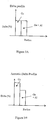
Figure 3a illustrates schematically the optical delta profile of one example of a reduced SBS single mode fiber not being part of the invention; -
Figure 3b illustrates schematically the longitudinal acoustic delta profile of the optical fiber that has the optical delta profile shown inFigure 3a ; -
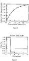
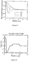
Figure 4 is a graph of relative SBS threshold as a function of Al concentration level (mole percent), in the core region corresponding to the radius r between 2 µm and 4.2 µm; -
Figure 5 illustrates acoustic delta profiles of one example of an optical fiber not being part of the present invention; -
Figure 6 is a plot of optical and longitudinal acoustic fields of the optical fiber that corresponds to the multi-step acoustic delta profile (dashed lines) ofFigure 5 ; -
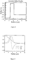
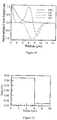
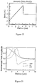
Figure 7 is a graph of relative SBS threshold as a function of Al doping concentration level (mole percent), in the optical core region corresponding to the radius r between 0 and 2.5µm; -
Figure 8 illustrates acoustic delta profile of a standard single mode fiber and of another example of an optical fiber not being part of the present invention; -
Figure 9 is a plot of optical and longitudinal acoustic fields of the optical fiber that corresponds to the multi-step acoustic delta profile ofFigure 8 ; -
Figure 10 illustrates the optical delta profile of a standard non zero dispersion shifted fiber (NZSDSF); -
Figure 11 illustrates the longitudinal acoustic delta profile of the optical fiber with the optical delta profile shown inFigure 10 ; -
Figure 12 is a plot of optical and longitudinal acoustic fields of the optical fiber that corresponds to the optical fiber corresponding toFigures 10 and 11 ; -
Figure 13 illustrates the longitudinal acoustic delta profile of an example of an optical fiber not being part of the present invention, that has the optical delta profile shown inFigure 10 ; -
Figure 14 is a plot of optical and longitudinal acoustic fields of the example of the optical fiber that corresponds to the multi-step acoustic delta profile ofFigure 13 ; -
Figure 15 illustrates the optical delta profile an optical laser fiber; -
Figure 16 is a plot of optical and longitudinal acoustic fields of the optical laser fiber that corresponds to the optical laser fiber that has optical delta profile ofFigure 15 ; -
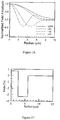
Figure 17 illustrates the longitudinal acoustic delta profile of the optical fiber according to an example not being part of the present invention that has the optical delta profile shown inFigure 15 ; -
Figure 18 is a plot of optical and longitudinal acoustic fields of the example of the optical fiber that corresponds to acoustic delta profile ofFigure 17 ; -
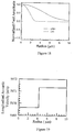
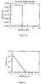
Figure 19 is a plot of the longitudinal acoustic velocity through the core and cladding of an optical fiber according to one embodiment of the present invention that has the optical delta profile ofFigure 2a ; -
Figure 20 illustrates the longitudinal acoustic delta profile of the optical fiber that corresponds to the plot ofFigure 19 ; -
Figure 21 is an optical refractive delta% contribution due to Al dopant in the fiber core of another exemplary fiber; -
Figure 22 is an acoustic delta profile of the optical fiber corresponding toFigure 21 ; and -
Figure 23 is a plot of optical and longitudinal acoustic fields of the optical fiber that corresponds to the optical fiber corresponding toFigures 21 and22 . - Additional features and advantages of the invention will be set forth in the detailed description which follows and will be apparent to those skilled in the art from the description or recognized by practicing the invention as described in the following description together with the claims and appended drawings.
- The "refractive index profile" is the relationship between refractive index or relative refractive index and waveguide fiber radius.
- The "relative refractive index percent" or "optical refractive index delta" is defined as Δ% = 100 x (ni 2 -nc 2)/2ni 2, where ni is the maximum refractive index in region i, unless otherwise specified, and nc is the average refractive index of the cladding region. As used herein, the relative refractive index is represented by Δ and its values are given in units of "%", unless otherwise specified. In cases where the refractive index of a region is less than the average refractive index of the cladding region, the relative index percent is negative and is referred to as having a depressed region or depressed index, and is calculated at the point at which the relative index is most negative unless otherwise specified. In cases where the refractive index of a region is greater than the average refractive index of the cladding region, the relative index percent is positive and the region can be said to be raised or to have a positive index. An "updopant" is herein considered to be a dopant which has a propensity to raise the refractive index relative to pure undoped SiO2. A "downdopant" is herein considered to be a dopant which has a propensity to lower the refractive index relative to pure undoped SiO2. An updopant may be present in a region of an optical fiber having a negative relative refractive index when accompanied by one or more other dopants which are not updopants. Likewise, one or more other dopants which are not updopants may be present in a region of an optical fiber having a positive relative refractive index. A downdopant may be present in a region of an optical fiber having a positive relative refractive index when accompanied by one or more other dopants which are not downdopants. Likewise, one or more other dopants which are not downdopants may be present in a region of an optical fiber having a negative relative refractive index.
- "Chromatic dispersion", herein referred to as "dispersion" unless otherwise noted, of a waveguide fiber is the sum of the material dispersion, the waveguide dispersion, and the inter-modal dispersion. In the case of single mode waveguide fibers the inter-modal dispersion is zero. Zero dispersion wavelength is a wavelength at which the dispersion has a value of zero. Dispersion slope is the rate of change of dispersion with respect to wavelength
- "Effective area" is defined as:

- The term "α-profile" refers to a relative refractive index profile, expressed in terms of Δ(r) which is in units of "%", where r is radius, which follows the equation,

- The mode field diameter (MFD) is measured using the Peterman II method wherein, 2w = MFD, and w 2 = (2∫ f 2(r)rdr / ∫ [df(r) / dr]2 rdr), the integral limits being 0 to ∞.
- The bend resistance of a waveguide fiber can be gauged by induced attenuation under prescribed test conditions.
- One type of bend test is the lateral load microbend test. In this so-called "lateral load" test, a prescribed length of waveguide fiber is placed between two flat plates. A #70 wire mesh is attached to one of the plates. A known length of waveguide fiber is sandwiched between the plates and a reference attenuation is measured while the plates are pressed together with a force of 30 newtons. A 70 newton force is then applied to the plates and the increase in attenuation in dB/m is measured. The increase in attenuation is the lateral load attenuation of the waveguide.
- The "pin array" bend test is used to compare relative resistance of waveguide fiber to bending. To perform this test, attenuation loss is measured for a waveguide fiber with essentially no induced bending loss. The waveguide fiber is then woven about the pin array and attenuation again measured. The loss induced by bending is the difference between the two measured attenuations. The pin array is a set of ten cylindrical pins arranged in a single row and held in a fixed vertical position on a flat surface. The pin spacing is 5 mm, center to center. The pin diameter is 0.67 mm. During testing, sufficient tension is applied to make the waveguide fiber conform to a portion of the pin surface.
- The theoretical fiber cutoff wavelength, or "theoretical fiber cutoff', or "theoretical cutoff', for a given mode, is the wavelength above which guided light cannot propagate in that mode. A mathematical definition can be found in Single Mode Fiber Optics, Jeunhomme, pp. 39-44, Marcel Dekker, New York, 1990 wherein the theoretical fiber cutoff is described as the wavelength at which the mode propagation constant becomes equal to the plane wave propagation constant in the outer cladding. This theoretical wavelength is appropriate for an infinitely long, perfectly straight fiber that has no diameter variations.
- The effective fiber cutoff is lower than the theoretical cutoff due to losses that are induced by bending and/or mechanical pressure. In this context, the cutoff refers to the higher of the optical LP11, and LP02 modes. LP11, and LP02 are generally not distinguished in measurements, but both are evident as steps in the spectral measurement, i.e. no power is observed in the mode at wavelengths longer than the measured cutoff. The actual fiber cutoff can be measured by the standard 2m fiber optical cutoff test, FOTP-80 (EIA-TIA-455-80), to yield the "fiber cutoff wavelength", also known as the "2m fiber cutoff" or "measured cutoff'. The FOTP-80 standard test is performed to either strip out the higher order modes using a controlled amount of bending, or to normalize the spectral response of the fiber to that of a multimode fiber.
- The cabled cutoff wavelength, or "cabled cutoff' is even lower than the measured fiber cutoff due to higher levels of bending and mechanical pressure in the cable environment. The actual cabled condition can be approximated by the cabled cutoff test described in the EIA-445 Fiber Optic Test Procedures, which are part of the EIA-TIA Fiber Optics Standards, that is, the Electronics Industry Alliance - Telecommunications Industry Association Fiber Optics Standards, more commonly known as FOTP's. Cabled cutoff measurement is described in EIA-455-170 Cable Cutoff Wavelength of Single-mode Fiber by Transmitted Power, or "FOTP-170".
- Kappa is the ratio of dispersion divided by dispersion slope at a particular wavelength. Unless otherwise noted herein, kappa is reported at a wavelength of 1550 nm.
- Unless otherwise noted herein, optical properties (such as dispersion, dispersion slope, etc.) are reported for the LP01 mode.
- A waveguide fiber telecommunications link, or simply a link, is made up of a transmitter of light signals, a receiver of light signals, and a length of waveguide fiber or fibers having respective ends optically coupled to the transmitter and receiver to propagate light signals there between. The length of waveguide fiber can be made up of a plurality of shorter lengths that are spliced or connected together in end to end series arrangement. A link can include additional optical components such as optical amplifiers, optical attenuators, optical isolators, optical switches, optical filters, or multiplexing or demultiplexing devices. One may denote a group of inter-connected links as a telecommunications system.
- A span of optical fiber as used herein includes a length of optical fiber, or a plurality of optical fibers fused together serially, extending between optical devices, for example between two optical amplifiers, or between a multiplexing device and an optical amplifier. A span may comprise one or more sections of optical fiber as disclosed herein, and may further comprise one or more sections of other optical fiber, for example as selected to achieve a desired system performance or parameter such as residual dispersion at the end of a span.
- Various wavelength bands, or operating wavelength ranges, or wavelength windows, can be defined as follows: "1310 nm band" is 1260 to 1360 nm; "E-band" is 1360 to 1460 nm; "S-band" is 1460 to 1530 nm; "C-band" is 1530 to 1565 nm; "L-band" is 1565 to 1625 nm; and "U-band" is 1625 to 1675 nm.
- When an optical wave propagates in an optical waveguide in which acoustic modes are present, the optical wave is scattered by the acoustic wave. The electric field that describes the SBS satisfies the nonlinear wave equation:


- From the above equations we can derive the equations for the optical power changes for the pump and the signal:


- Equation (10) shows that the SBS gain coefficient depends on two parameters that related to fiber design: one is the optical effective area Aeff, the other is the overlap integral

- To capture the effects from both the optical effective area and the overlap integral, we define a figure of merit (FOM) by taking the ratio of optical effective area over the overlap integral:

- The SBS power grows exponentially with fiber length. For uniform Brillouin frequency shift along the fiber, the peak SBS power threshold is inversely proportional to the gain coefficient and fiber effective length:


- In order to improve the SBS performance of an optical fiber, the figure of merit F should be designed to take a larger value than a conventional fiber without the optimized performance in SBS. The ratio of the F of the fiber being designed to that of a reference fiber is the factor that the SBS threshold is improved. It is also converted into dB unit as described in this invention disclosure.
- It can be seen from Equations (5) and (7) that the optical field and longitudinal acoustic field are governed by similar type of scalar wave equations. The two equations can be written in the same form for the fundamental optical mode and the acoustic mode with no azimuthal variation that are involved in the SBS


- For an acoustic mode, fa (r) is the acoustic field distribution and the acoustic refractive index is defined as


- In practice, the (optical) refractive index profile is often described by the optical delta profile or optical refractive index delta profile. We can also similarly define the delta for the acoustic refractive index so that each optical refractive index profile is also associated with a corresponding acoustic delta profile that describes the (longitudinal) acoustic behavior of longitudinal acoustic field. Using the index definitions for the optical and acoustic waves, we can describe the optical and acoustic delta profiles using the following equation:

- The optical refractive index of the core as the function of the Ge doping concentration is described by the following equation,


- An optical waveguide fiber which is optically single-moded at a particular wavelength may be multi-moded acoustically at the same optical wavelength (assuming λ=1.55 µm) because the acoustic wavelength corresponding to Brillouin frequency is of the order of 0.55 microns, which is quite small compared to typical optical waveguide fiber dimensions. (See Eqs. (16) and (17).) In the case of spontaneous Brillouin scattering at relatively low launch powers, the incident optical field is Brillouin scattered by each of the acoustic modes and Brillouin gain spectrum shows peaks corresponding to optical field interaction with each of the acoustic modes. At relatively high launch powers, the SBS threshold is exceeded, and one of the acoustic modes typically becomes dominant while the other acoustic modes do not survive the mode competition, leading to the onset of stimulated Brillouin scattering.
- As coupling between the optical mode field and the acoustic mode field(s) increases, more optical power is undesirably reflected opposite to the direction of optical signal transmission.
- As disclosed herein, the coupling between the optical and acoustic modes is preferably reduced via the refractive (i.e., optical) and acoustic index profiles of the optical fiber disclosed herein. In some embodiments, optical mode field remains extended while acoustic fields become more tightly confined to one region of the core to reduce overlap between the optical mode field and the acoustic fields. In some embodiments the confinement of acoustic power in the core is reduced by spreading the acoustic field, which is achieved by matching the acoustic velocity in the core and cladding (i.e., making theses velocities the same or essentially the same).
- Thus, in some of the examples, the
optical fiber 10 disclosed herein (seeFigure 1 ) tends to pull the mode field of the dominant acoustic mode field (for example, L01) either (a) in toward the centerline of the optical fiber, or (b) outward towards the edge of the core 12, resulting in reduced coupling between the acoustic and optical fields. Preferably, theoptical fiber 10 also tends to pull the mode field of the next dominant acoustic mode field (typically L02) either (a) in toward the centerline of the optical fiber, or (b) outward towards the edge of the core, resulting in reduced coupling between this next dominant acoustic mode field and the optical field. In the embodiment of the present invention, the acoustic velocity of the core and the cladding are about the same, and the acoustic field extends over the cladding, leaving much less acoustic energy in the core, again minimizing the overlap integral between the optical and acoustic fields. - The Brillouin frequency for optical fiber as disclosed herein is preferably between about 9.5 to 12 GHz, for the 1550 nm wavelengths (and is higher when measured at shorter wavelengths).
- We have found that a higher dopant concentration of the materials that reduce acoustic field velocity (for example Ge), at or near the optical fiber centerline, and in particular in a central portion of the core of the optical fiber, than that in the region away from the central core that has more Al dopant, forces the acoustic modes to be more tightly confined in that central core region (
core region 12a). Higher concentration of Al dopant near the central core increases the longitudinal acoustic velocity in that region and shifts acoustic modes toward the edge of the core (region 12b). - Preferably, the core is comprised of silica doped with an optical index (of refraction) raising dopant, for example germanium, i.e. germania doped silica. At least one section of the core is also co-doped with Aluminum- i.e., it includes both Ge and Aluminum. Germania increases the optical refractive index while decreasing longitudinal acoustic velocity of the acoustic wavefront (thereby increasing "effective refractive index" of the acoustic wave). Aluminum increases the optical refractive index while also increasing longitudinal acoustic velocity of the acoustic (sound) wavefront (thereby decreasing the "effective refractive index" of the acoustic wave). Having at least one section of the core co-doped with both Ge and Aluminum achieves the desired optical refractive index (or refractive index delta) while changing the longitudinal acoustic velocity of the core, thus resulting in decreased overlap between the acoustic wave (field) and the optical wave (or field), decreasing the SBS. This approach allows us to keep the desired optical profile without changing the optical properties, while simultaneously changing/controlling the acoustic wave velocity and minimizing or eliminating SBS.
- The core may comprise a first portion (
core region 12a) extending from the centerline to a radius of about 2 µm. Alternatively the core may comprise a first portion (core region 12a) extending from the centerline to a distance of about 0.2r to 0.5r, where r is the core radius. - It is preferred, for optical transmission fiber, that peak or maximum (optical) refractive index delta is 0.3 %<ΔMAX <1.4%, the optical effective area at 1550 nm between 50 and 140µm2, preferably larger than 80 µm2, more preferably between 80 and 120 µm2, even more preferably between 80 and 110 µm2. It is preferred, for optical laser fiber, that peak or maximum refractive index delta ΔMAX is about 0.05 %<ΔMAX <0.3%, the optical effective area at 1550 nm between larger than 140µm2, preferably larger than 150 µm2, more preferably between 159 and 2000 µm2. It is preferred, for optical DC (dispersion compensating) fiber, that peak or maximum (optical) refractive index delta is about 1%<ΔMAX <3%, the optical effective area at 1550 nm between larger than 20 µm2, preferably larger than 30 µm2, more preferably between 30 and 40 µm2. It is preferred, for nonlinear optical fiber that peak or maximum refractive index delta is about 1%<ΔMAX <3%, the optical effective area at 1550 nm is less than 40 µm2.
- As described above, SBS originates from the interaction between optical wave and acoustic wave. In a single optical fiber, the gain of SBS depends on the SBS spectrum and the overlap between the optical mode and acoustic modes. Thus, one way to reduce the overlap between the optical mode and acoustic modes by fiber profile designs is to allow the optical refractive index profile (optical delta profile) to remain the same, while changing the acoustic delta profile of the fiber.
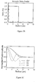
- In order to form an acoustic waveguide within the fiber core, the longitudinal and shear acoustic velocities must be lower in the fiber core than in the cladding. This is normally the case for optical fibers with a typical Ge up-doped core without other co-dopants. For a standard single mode fiber, the optical delta profile is typically a step function as shown in
Figure 2A . The core of the fiber is doped with about 4.2 mol% Ge, which results in a relative refractive (i.e., optical) index delta% of 0.35%, relative to pure silica cladding (Figure 2a ). This positive relative refractive index delta corresponds to the optical waveguiding core. This standard single mode fiber has a MFD of 10.22 µm, effective area of 80.13 µm2, and chromatic dispersion of 16.71 ps/(nm.km) at 1550 nm. The core delta is due to only Ge. The core includes no other dopants. Because the interaction between the acoustic wave and optical wave is dominated by the longitudinal acoustic wave, in the following paragraphs, we discuss the longitudinal acoustic wave only. For acoustic waves, the relative longitudinal acoustic delta profile for this standard single mode fiber is shownFigure 2B .Figures 2A and2B illustrate that the longitudinal acoustic waves are guided inside the region of the same size as the size as the optical waveguiding core (i.e., within the radius of 4.0µm), which results in a large overlap between the fundamental optical mode and lower order acoustic modes (and an overlap integral of about 0.97). Thus, this type of fiber has a relatively large amount of SBS. The confinement of the LP01 optical field and several lowest orders of the longitudinal acoustic fields for this fiber are shown inFigure 2C . - In order to reduce SBS, the
optical fiber 10 comprises at least one region of a silica-basedcore 12 that includes both the Ge and another updopant that increases acoustic velocity, for example, Aluminum. (See Eqs (19-20). For example, one of the core regions may have more than 0.1 mole% Aluminum and that an adjacent core region may have no Al or less than 0.1 mole% of Al. As stated above, both the Ge and Al increase the optical refractive index of the glass, but Al increases the longitudinal acoustic velocity and Ge decreases the longitudinal acoustic velocity. Thus, by utilizing the combination of Ge and Al, we can design fibers with the same optical refractive index profile as a typical transmission fiber (for example, standard single mode fiber) but different acoustic delta profile. Of course, other type of fibers may also be designed by utilizing the same approach to provide the same optical delta profile, while having a different acoustic delta profile and, therefore, improved SBS. These optical fibers include DC fibers, laser fibers, and non-linear optical fibers. It is noted that dopants other than Al may also be utilized, as long as they increase the longitudinal acoustic velocity, relative to that of silica glass. -
Figure 1 illustrates an exemplaryoptical fiber 10 not being part of the invention. The optical delta profile offiber 10 is the same as that of the standard single mode fiber inFigure 2A , except that both Ge and Al are used in aregion 12b surrounding thecore region 12a. In this example, the dopant levels of Ge and Al are selected such that the refractive index is the same as the rest of the core (region 12a) that does not contain Al (is doped with Ge only). Because the optical delta profile of thisfiber 10 is the same as that of standard single mode fiber (SeeFigure 3a ), the optical properties of this modifiedoptical fiber 10 remain essentially the same as those for the standard single mode fiber. - The longitudinal acoustic delta profile of the
fiber 10 is illustrated inFigure 3b . The longitudinal acoustic delta profile of the fiber 10 (corresponding toFigure 3b ) is very different from that of the standard single mode fiber that is doped with Ge only (shown inFigure 2b ). Because Al increases the acoustic velocity, the longitudinal acoustic delta is decreased in the region when Al is doped so that acoustic delta profile has a peak in the center, which guides the lower order acoustic modes within it. As a result, the overlap between the fundamental optical mode and lower order acoustic modes is reduced and the SBS threshold is increased. The SBS threshold of fiber 10 (corresponding toFigures 1 and3a -3b) is increased from that of the standard single mode fiber. The approach for reducing SBS can be also applied to other more complicated segmented core designs, for example for NZDSF applications. - Thus,
optical fiber 10 utilizes silica doped core that includes Aluminum and another codopant (index increasing co-dopant) such as Ge to form a narrower waveguide for the longitudinal acoustic field than for the optical field, so that the longitudinal acoustic field is much more confined near the center of the core (compared to the fiber with a core that does not include Al, or a similar material as a co-dopant). While the optical field is unaffected, the overlapping between the optical field and the longitudinal acoustic field is reduced, resulting in suppression of SBS effect and in increase in SBS threshold. The SBS threshold of an optical fiber is the highest total optical power that can transmit through the fiber. - We will compare the performance of the
exemplary fibers 10 with that of a standard single mode transmission fiber (fiber 1), i.e., the fiber that does not contain F. We then doped thecore region 12b (r =2-4.2 µm) of theoptical fiber 10 with varying level of the Al while maintaining the overall delta to be the same as that of the optical fiber doped with Ge only, so that the optical properties of the optical fiber, including MFD, effective area, and dispersion were essentially unchanged. The modeling results are summarized in Table 1. We found that as we increase the level of Al in thecore region 12b, the SBS threshold relative to that in exemplary fiber 1 (standard single mode fiber corresponding toFigures 2A and2B ) increases monotonically, which is also illustrated inFigure 4 .TABLE 1 0-2 µm 2-4.2 µm Case No. Ge02 Delta (%) Al Delta (%) GeO2 Delta (%) Al Delta (%) L01 FOM Power (P0) Power Improvement (dB) Overlap Integral 1 0.35 0 0.35 0 82.21 1.00 0.00 0.98 2 0.35 0 0.3 0.05 107.06 1.30 1.15 0.75 3 0.35 0 0.25 0.1 128.60 1.56 1.94 0.62 4 0.35 0 0.2 0.15 141.63 1.72 2.36 0.57 5 0.35 0 0.15 0.2 150.43 1.83 2.62 0.53 6 0.35 0 0.1 0.25 156.68 1.91 2.80 0.51 7 0.35 0 0.05 0.3 161.42 1.96 2.93 0.50 - The mechanism of the improvement of SBS threshold can be understood by looking at the acoustic waveguide and the related acoustic field distribution. For example, the acoustic delta profile for the
optical fiber 10 of theexemplary fiber 6 of Table 1 is shown inFigure 5 . We have found that, with the Aluminum co-doping, the acoustic delta decreases significantly. Therefore, thecore region 12a (r <2µm, in this example) forms a narrower waveguide for the acoustic field, while the optical fields still propagate through the same optical wave-guidingcore 12.Figure 6 illustrates the optical and acoustic fields as a function of fiber radius, for theexemplary fiber 6. We found that the L01 acoustic field is essentially confined to the region of thecore 12a with a radius of less than 2 microns, while the optical field is unchanged, which increases the figure of merit FOM that measures the SBS performance. The higher order acoustic fields are oscillating in nature. The overlap of such fields with the optical field (e.g., LP01) is very small, because their positive contribution is largely cancelled by their negative contribution. For the optical fiber of example 6 the overlap integral is 0.51. The Pin Array bending and the lateral load bending loss for theoptical fiber 10 of this example are 7.9 dB and 0.45dB/km, respectively, at 1550 nm. This fiber has a cut-off wavelength at or below 1.3 µm. - In this example, we explore another mechanism to reduce the SBS effect. Again, we use the Ge doped standard single mode fiber (
Figures 2A and2B ) as a reference fiber. But in these examples we co-doped thecentral core region 12a (r =0 to 2.5 microns) with Al while leaving the surroundingcore region 12b (the core region with the radius from 2.5 microns to 4.2 microns) unchanged. We found that as we increase the doping level of Aluminum in theregion 12a as shown in Table 2, the SBS threshold increases monotonically as shown inFigure 7 .Table2 0-2.5 µm 2.5-4.2 um Case No. GeO2 Delta (%) Al Delta (%) Ge02 Delta (%) Al Delta (%) L01 FOM Power (P0) Power Improvement (dB) Overlap Integral 1 0.35 0 0.35 0 82.21 1 0.00 0.98 8 0.35 0.03 0.35 0 89.96 1.09 0.39 0.89 9 0.35 0.06 0.35 0 114.82 1.40 1.45 0.70 10 0.35 0.1 0.35 0 142.82 1.74 2.40 0.56 11 0.35 0.15 0.35 0 165.74 2.02 3.05 0.48 12 0.35 0.2 0.35 0 180.84 2.20 3.42 0.44 13 0.35 0.25 0.35 0 191.57 2.33 3.67 0.42 14 0.35 0.3 0.35 0 199.66 2.43 3.85 0.40 15 0.35 0.35 0.35 0 206.63 2.51 4.00 0.39 - The mechanism of the improvement of SBS threshold by co-doping a core region that is centermost core region can be understood by looking at the acoustic waveguide and the related field distribution of the optical fiber examples depicted in Table 2. For example, the acoustic delta profile for the
optical fiber 10 of theexemplary fiber # 12 of Table 1 is shown inFigure 8 . We have found that, with the Aluminum co-doping in thecore region 12a, the acoustic delta decreases significantly. Therefore, acoustic delta of thecore region 12a (r = 0 to 2.5 microns) is depressed relative to that of theregion 12b (r = 2.5 to 4.2 microns), while the optical fields still propagate the width of theoptical waveguiding core 12. This acoustic delta profile would result in the fundamental acoustic field being pulled away from the center of thefiber core 12.Figure 9 illustrates optical and acoustic fields as a function of fiber radius. We found that the L01 acoustic field is pushed away from the center of the core towards the edge of the core 12, while the optical field is unchanged. Since the optical field is mostly near the center of the fiber (i.e., in thecore region 12a), by moving the fundamental acoustic field away from the center of the fiber core, we reduce the overlap between the LP01 and L01 fields and increase the FOM that measures the SBS performance. The higher order acoustic fields are oscillating in nature. The overlap of such fields with the optical field (e.g., LP01) is very small, because their positive contribution is largely cancelled by their negative contribution. For the optical fiber of opticalfiber example # 12 from Table 2 the overlap integral is 0.44. The Pin Array bending and the lateral load bending loss for theoptical fiber 10 of this example are 7.9 dB and 0.45dB/km, respectively, at 1550 nm. The optical fiber examples of Table 2 have a cut-off wavelength at or below 1.3µm. - In the above examples, we have used a multiple step acoustic delta profile to illustrate that doping at least one core region with at least two dopants, while leaving one core region doped with a single updopant, such as Ge, for example, improves the SBS threshold of
optical fibers 10. Preferably, the tworegions core - For example, the
central core region 12a may include Ge and Al co-doped silica and theadjacent core region 12b surrounding thecentral core region 12 a may includes only Ge doped silica. Alternatively, thecentral core region 12a may include Ge doped silica only and theadjacent core region 12b surrounding the central core region includes Ge and Al co-doped silica and does not include Al doped silica. Alternatively, the optical fiber may have at a least twoadjacent regions core regions Such fibers 10 have a reduced overlap integral of less than 0.8 at 1550 nm. Preferably, the overlap integral is less than 0.65. More preferably, the overlap integral is less than 0.5. - In actual manufactured fibers, the boundary between
different regions fiber core regions 12i may also be added as long as the at least one of the core regions is codoped with both Ge and Al, or other similar dopants. - The optical delta profile and acoustic delta profile of a typical large area NZDSF fiber is shown in
Figures 10 and 11 , respectively. This fiber has a dispersion of 4.1 ps/nm/km at 1550 mn, Kappa of 48 nm at 1550 nm, dispersion of -15.73 ps/nm/km at 1310 nm, zero dispersion around 1500 nm, MFD of 9.82 µm at 1550 nm, MFD of 7.61 µm at 1310 nm, effective area of 72.52 µm2 at 1550 nm. This fiber has an acoustic FOM of 114.35 µm2. The optical field and longitudinal acoustic fields of this fiber are shown inFigure 12 . - Now, we consider a case when Al dopant is added. Since both Ge and Al are up-dopant, we can not add Al arbitrarily. Al can only be added in the region where there is already positive delta. In this example, we have Al doped at a radial region of the core between radii of 1.2 to 3.7 microns, to contribute to most of the overall delta in this core region, and the Ge amount was correspondingly adjusted so that the overall optical delta profile was maintained the same as that shown
Figure 11 . The optical properties of this exemplary optical fiber 10 (such as the dispersion, MFD and optical effective area) are similar to the fiber when the positive delta was due only to Ge doping. However, the acoustic delta profile has been changed. The acoustic delta profile of the alteredfiber 10 is shown inFigure 13 . Thisoptical fiber 10 has FOM of 212.37 mm2 (L01) and 219.9 mm2 (L02). The SBS threshold is improved from the fiber without Al doping by a factor of 1.86 or by 2.69 dB. The optical field LP01 and longitudinal acoustic fields of thisexemplary fiber 10 are shown inFigure 14 . It is seen that with the introduction of Al doping in one core region away from the central core, the optical field is unchanged, but the L01 longitudinal acoustic field is confined to a much narrower region near the fiber center (i.e.,core region 12a). Theoptical fiber 10 of this example has the Pin Array bending loss and the lateral load bending loss of 7.5 dB and 2.4 dB/km, respectively, at 1550 nm. This fiber has a cut-off wavelength at or below 1.7 µm and a cable cutoff of 1.5 µm. - A silica-based laser fiber with 0.1% delta between the core and the cladding has an optical delta profile shown in
Figure 15 . In this optical fiber, both the core and the cladding of are doped with Ge. The optical fiber core is also co-doped with a small amount of rare earth material, for example Nd, Tm, Er and/or Yb to provide amplification. However, no other codopants are present in the core. This optical fiber has a MFD of 19.1 µm at 1550 nm and an, optical effective area of 271.2 µm2. The FOM of the L01 mode that measures the SBS performance is 296.9 µm2. The optical field and the longitudinal acoustic fields of this laser fiber are shown inFigure 16 . More specifically,Figure 16 illustrates that the optical field (LP01) and the acoustic field (L01) have an almost total overlap (i.e., there is very little area of no overlap) and both fields are spread over the entire width of the optical fiber core. - We then modified the composition of the fiber core by co-doping the Al in the
core region 12b (radius 2.5 to 6.0 µm) with Al. The amount of Al contributes to optical refractive index delta by 0.3% delta, and the Ge concentration in thecore region 12b was adjusted to provide 0.25 delta % to maintain the overall optical delta profile. That is, theresultant fiber 10 still has the original optical delta profile shown inFigure 15 . The acoustic delta profile of theresultant fiber 10 is shown inFigure 17. Figure 17 illustrates an acoustic delta profile that has a dip in thecore region 12b. That is, theresultant laser fiber 10 has a narrow and deep acoustic waveguide in the center of the core for the acoustic field, improving the SBS threshold. The multi-step acoustic delta profile ofFigure 17 accounts for different acoustic velocities between thecore regions core regions optical laser fiber 10 of this example differ by around 228.9 m/s with the longitudinal acoustic velocity in thecore region 12a being 5899 m/s and that incore region 12b being 6140.2 m/s.Optical laser fiber 10 of this example has a FOM of 956.9 µm 2, which suggests that the SBS threshold has been increased by a factor of 3.22 or 5.08 dB. The optical fields and the acoustic fields of this laser fiber 10 (with the optical and acoustic delta profiles shown inFigures 15 and17 ) are illustrated inFigure 18. Figure 18 illustrates that the optical field (LP01 mode) occupies theentire core 12, while the acoustic field L01 is confined to thecore region 12a, minimizing the overlap between the optical and acoustic fields. - Alternatively, we can also dope Al in the central core region of the laser fiber, for example, with Al contributing 0.25% delta between 0 and 4.0 µm2. The FOM becomes 697.25 µm 2. The SBS threshold can be improved from the fiber shown in
Figure 15 without Al doping by a factor of 2.35 or 3.7 dB. - We can also modify the laser fiber to have a larger core diameter. For example, if the core diameter is changed to 25 µm 2 , without the doping of Al, the optical laser fiber has a MFD of 22.8 µm, effective area of 437 µm 2 and FOM of 436 µm 2 at 1550 nm. We then modified the composition of the fiber core by co-doping the Al in the
core region 12b (radius 4.0 to 8.0 µm) with Al. The Al dopant contributes to optical refractive index delta by 0.3% delta, and the Ge concentration in thecore region 12b was adjusted to provide 0.25 delta %, to maintain the overall optical delta profile. While the MFD and optical effective area were not changed, the FOM changed to 1864 µm 2. The SBS threshold was increased by a factor of 4.27 or 6.3dB. - According to the embodiment of the present invention the
optical fiber 10 has acore 12 and thecladding 14 doped such that longitudinal acoustic velocities within the core and the cladding are matched. When the longitudinal acoustic velocities within the core and the cladding of theoptical fiber 10 are the same or almost the same (i.e., matched) we achieve very good SBS improvement. - Again, for comparison purposes, we consider an optical fiber with a simple step-index optical delta profile shown in
Figure 2a . As stated above, This optical fiber has a MFD of 10.22 µm, effective area of 80.13 µm2, chromatic dispersion of 16.71 ps/(nm.km) at 1550 nm and FOM is 82.2 µm2. - We then modified the composition of this optical fiber to create new
exemplary fiber 10, by doping the core with Al to provide 0.2925% delta (due to Al only), and by doping the cladding with Al to provide 0.1% delta contribution, while maintaining the overall optical delta profile to be the same as that inFigure 2a . This exemplaryoptical fiber 10 has the FOM of 196.7 µm2, which is a factor of 2.39 or 3.79 dB improvement in SBS threshold. Preferably, the acoustic velocities between the core and the cladding of this type offiber 10 are different no more than 0.3% and more preferably by no more than 0.1% and most preferably by no more than 0.05%. Also preferably, difference between the core acoustic velocity v1 and the cladding acoustic velocity v2 (i.e., |v1-v2|) for this type offiber 10 is no more than 60 m/s, preferably, less than 25 m/s, more preferably less more than 10 m/s, even more preferably less than 5m/s and most preferably less than 3m/s. A typical range for v1-v2 is between -5 m/s and 60m/s. In this exemplaryoptical fiber 10, the longitudinal velocities of the core and the cladding are matched to be within about 2 m/s of one another (Figure 19 ). The close match of acoustic velocities is also illustrated in the acoustic delta profile ofFigure 20 , which shows acoustic delta % of the core (relative to the cladding) of about 0.0275% In order to improve the SBS threshold significantly, the match between the core and cladding in terms of longitudinal velocity or acoustic delta must be very close. For example, if we change the Al concentration in the cladding such that it contributes to 0.291 delta%, the FOM changes to 117.75 µm2, and the improvement of the SBS threshold is a factor of 1.43 or 1.56 dB. - According to another example not being part of the present invention the
optical fiber 10 has acore 12 and thecladding 14 doped such that the dopant level of Al does not change abruptly between the adjacent regions, but undergoes very smooth change. However, one can find at least 2 core regions with a different amount of Al dopant, and thus different acoustic velocities. In this example, we consider theoptical fiber 10 that has the optical delta profile ofFigure 2a , but has an Al doped core. In this example, the level of Al is changed linearly from the center of the core 12, to the edge of the core. The optical Delta % contribution due to changing Al concentration of this optical fiber is depicted inFigure 21 . The acoustic delta profile of this fiber is shown inFigure 22 . The lower value of the acoustic delta near the center of thecore 12 helps to push the acoustic field away from the center of the core, resulting in reduction of the overlap between the LP01 optical field and the acoustic fields. The FOM of this modifiedoptical fiber 10 is 191.7 µm 2, which is a factor of 2.33 or 3.68dB improvement over that is purely doped with Ge. The optical field and acoustic fields are shown inFigure 23 . It is found that the fundamental acoustic field is pushed away from the center of the core while the LP01 remains in the center of the core. - Preferably, the optical fiber disclosed herein has a silica-based core and cladding. In preferred embodiments, the cladding has an outer diameter of about 125 µm. Preferably, the outer diameter of the cladding has a constant diameter along the length of the optical fiber. In preferred embodiments, the refractive index of the optical fiber has radial symmetry.
- It is to be understood that the foregoing description is exemplary of the invention only and is intended to provide an overview for the understanding of the nature and character of the invention as it is defined by the claims. The accompanying drawings are included to provide a further understanding of the invention and are incorporated and constitute part of this specification. The drawings illustrate various features and embodiments of the invention which, together with their description, serve to explain the principals and operation of the invention. It will become apparent to those skilled in the art that various modifications to the preferred embodiment of the invention as described herein can be made without departing from the scope of the invention as defined by the appended claims.
Claims (8)
- An optical fiber (10), comprising:a core (12) having a refractive index profile and a centerline; anda cladding layer (14) surrounding and directly adjacent the core (12);wherein the core includes updoping material and is doped with Al in at least one region of the core (12), characterized in that
the difference between the refractive index for longitudinal acoustic waves within the core (12) and the refractive index for longitudinal acoustic waves within the cladding layer (14) is 0.0275% or less than 0.0275%. - The optical fiber (10) according to claim 1, wherein the Al concentration in said at least one region of the core is such that 0.2925% optical delta is due to Al only with respect to an undoped region of the core (12).
- The optical fiber (10) according to one of the claims 1 and 2, wherein the cladding layer (14) is doped with Al in such a concentration that the Al provides up to 0.1% optical delta contribution due to Al only with respect to an undoped cladding layer (14).
- The optical fiber (10) according to claim 1, wherein the acoustic velocities between the core and the cladding are different by no more than 0.3%.
- The optical fiber (10) according to claim 5, wherein the acoustic velocities between the core (12) and the layer (14) are different by no more than 0.1%.
- The optical fiber (10) according to claim 5, wherein the absolute difference between the core acoustic velocity v1 and the cladding acoustic velocity v2, i.e. |v1-v2| is no more than 60 m/s.
- The optical fiber (10) according to claim 6, wherein the absolute difference between the core acoustic velocity v1 and the cladding acoustic velocity v2, i.e. |v1-v2| is less than 25 m/s.
- The optical fiber (10) according to claim 7, wherein the absolute difference between the core acoustic velocity v1 and the cladding acoustic velocity v2, i.e. |v1-v2| is less than 10 m/s.
Priority Applications (1)
| Application Number | Priority Date | Filing Date | Title |
|---|---|---|---|
| EP19161688.7A EP3521878A1 (en) | 2005-06-15 | 2006-06-06 | High sbs threshold optical fiber with aluminium dopant |
Applications Claiming Priority (2)
| Application Number | Priority Date | Filing Date | Title |
|---|---|---|---|
| US69118005P | 2005-06-15 | 2005-06-15 | |
| PCT/US2006/021988 WO2007053198A2 (en) | 2005-06-15 | 2006-06-06 | High sbs threshold optical fiber with aluminium dopant |
Related Child Applications (2)
| Application Number | Title | Priority Date | Filing Date |
|---|---|---|---|
| EP19161688.7A Division EP3521878A1 (en) | 2005-06-15 | 2006-06-06 | High sbs threshold optical fiber with aluminium dopant |
| EP19161688.7A Division-Into EP3521878A1 (en) | 2005-06-15 | 2006-06-06 | High sbs threshold optical fiber with aluminium dopant |
Publications (3)
| Publication Number | Publication Date |
|---|---|
| EP1891472A2 EP1891472A2 (en) | 2008-02-27 |
| EP1891472A4 EP1891472A4 (en) | 2011-10-19 |
| EP1891472B1 true EP1891472B1 (en) | 2019-09-11 |
Family
ID=38006354
Family Applications (2)
| Application Number | Title | Priority Date | Filing Date |
|---|---|---|---|
| EP06844136.9A Expired - Fee Related EP1891472B1 (en) | 2005-06-15 | 2006-06-06 | High sbs threshold optical fiber with aluminium dopant |
| EP19161688.7A Withdrawn EP3521878A1 (en) | 2005-06-15 | 2006-06-06 | High sbs threshold optical fiber with aluminium dopant |
Family Applications After (1)
| Application Number | Title | Priority Date | Filing Date |
|---|---|---|---|
| EP19161688.7A Withdrawn EP3521878A1 (en) | 2005-06-15 | 2006-06-06 | High sbs threshold optical fiber with aluminium dopant |
Country Status (4)
| Country | Link |
|---|---|
| US (1) | US7558461B2 (en) |
| EP (2) | EP1891472B1 (en) |
| JP (2) | JP5410750B2 (en) |
| WO (1) | WO2007053198A2 (en) |
Families Citing this family (20)
| Publication number | Priority date | Publication date | Assignee | Title |
|---|---|---|---|---|
| US8965162B2 (en) * | 2006-09-27 | 2015-02-24 | Peter Dragic | Anti-guiding waveguides |
| US7840110B1 (en) * | 2006-09-27 | 2010-11-23 | Peter Danny Dragic | Optical waveguide |
| US7577178B2 (en) * | 2007-01-23 | 2009-08-18 | Peter Dragic | Narrow linewidth injection seeded Q-switched fiber ring laser based on a low-SBS fiber |
| JP2009058876A (en) * | 2007-09-03 | 2009-03-19 | Furukawa Electric Co Ltd:The | Optical fiber |
| US7627219B2 (en) * | 2007-11-01 | 2009-12-01 | Ofs Fitel Llc | Large mode area fiber amplifiers with reduced stimulated brillouin scattering |
| US7822314B1 (en) * | 2008-07-02 | 2010-10-26 | The United States Of America As Represented By The Secretary Of The Air Force | Segmented acoustic core photonic crystal fiber laser |
| WO2010085605A1 (en) * | 2009-01-23 | 2010-07-29 | Nufern | Optical fiber with suppressed stimulated brillouin scattering |
| US8948550B2 (en) * | 2012-02-21 | 2015-02-03 | Corning Incorporated | Sensing systems and few-mode optical fiber for use in such systems |
| JP5694266B2 (en) * | 2012-10-02 | 2015-04-01 | 株式会社フジクラ | Optical fiber and fiber laser device using the same |
| JP5771586B2 (en) * | 2012-10-16 | 2015-09-02 | 株式会社フジクラ | Optical fiber and fiber laser device using the same |
| WO2014145426A1 (en) | 2013-03-15 | 2014-09-18 | Schott Corporation | Optical fiber for the reduction of stimulated brillouin scattering in high-power applications |
| US9356416B2 (en) | 2013-03-15 | 2016-05-31 | Ofs Fitel, Llc | Suppression of stimulated brillouin scattering in higher-order-mode optical fiber amplifiers |
| WO2016017743A1 (en) | 2014-08-01 | 2016-02-04 | 株式会社フジクラ | Optical fiber and method for producing same |
| CN107111055B (en) | 2014-09-26 | 2020-02-21 | 株式会社藤仓 | Optical fiber |
| WO2016047675A1 (en) * | 2014-09-26 | 2016-03-31 | 株式会社フジクラ | Optical fiber and method for manufacturing same |
| EP3488274B1 (en) * | 2016-07-20 | 2023-05-03 | University of Rochester | Lma fibers for suppression of thermal mode instability |
| US10677050B2 (en) | 2017-05-16 | 2020-06-09 | Baker Hughes, A Ge Company, Llc | Dispersion-shifted optical fibers for downhole sensing |
| US10408996B2 (en) * | 2017-11-30 | 2019-09-10 | Sterlite Technologies Limited | Non-zero dispersion shifted fiber with low cut off wavelength and large effective area |
| EP3562066A1 (en) * | 2018-04-27 | 2019-10-30 | Institut Mines-Telecom | Optical transmission system and method for core selection in multi-core fibers |
| CN112368615B (en) | 2018-07-02 | 2023-05-02 | 住友电气工业株式会社 | Optical fiber |
Family Cites Families (13)
| Publication number | Priority date | Publication date | Assignee | Title |
|---|---|---|---|---|
| SE410827B (en) * | 1978-03-22 | 1979-11-12 | Linden Alimak Ab | DEVICE FOR SEPARATING FINEER GOODS FROM GROSS GOODS |
| US4348075A (en) * | 1979-10-09 | 1982-09-07 | Westinghouse Electric Corp. | Bulk acoustic wave integrated optical deflector and monolithic A/D converter using such deflector |
| JPH01237507A (en) * | 1987-12-04 | 1989-09-22 | Nippon Telegr & Teleph Corp <Ntt> | Absolute single polarizing optical fiber |
| CA2053212A1 (en) * | 1991-10-11 | 1993-04-11 | Cheng-Kuei Jen | Optical fibers with preset stimulated backward brillouin scattering thresholds |
| JP3257328B2 (en) | 1995-03-16 | 2002-02-18 | 株式会社日立製作所 | Plasma processing apparatus and plasma processing method |
| CN1265199A (en) | 1997-07-15 | 2000-08-30 | 康宁股份有限公司 | Suppression of stimulated brillouin scattering in optical fiber |
| US6587623B1 (en) | 2000-08-14 | 2003-07-01 | The Board Of Trustees Of The University Of Illinois | Method for reducing stimulated brillouin scattering in waveguide systems and devices |
| US6687440B2 (en) * | 2001-02-28 | 2004-02-03 | The Boeing Company | Optical fiber having an elevated threshold for stimulated brillouin scattering |
| US6766075B1 (en) * | 2001-05-11 | 2004-07-20 | Pc Photonics Corporation | Side pumping of optical fiber systems via multiple delivery fibers |
| US20030235368A1 (en) * | 2002-06-03 | 2003-12-25 | Adtek Photomask Inc.; And | Pi -Shifted filters based on electro-optically induced waveguide gratings |
| US6959022B2 (en) * | 2003-01-27 | 2005-10-25 | Ceramoptec Gmbh | Multi-clad optical fiber lasers and their manufacture |
| WO2005054916A2 (en) * | 2003-11-26 | 2005-06-16 | Corning Incorporated | High sbs threshold nzds optical fiber |
| US7167621B2 (en) * | 2004-11-03 | 2007-01-23 | Nufern | Optical fiber with suppressed stimulated Brillouin scattering and method for making such a fiber |
-
2006
- 2006-06-06 EP EP06844136.9A patent/EP1891472B1/en not_active Expired - Fee Related
- 2006-06-06 JP JP2008516934A patent/JP5410750B2/en not_active Expired - Fee Related
- 2006-06-06 EP EP19161688.7A patent/EP3521878A1/en not_active Withdrawn
- 2006-06-06 WO PCT/US2006/021988 patent/WO2007053198A2/en active Application Filing
- 2006-06-14 US US11/453,450 patent/US7558461B2/en not_active Expired - Fee Related
-
2013
- 2013-09-18 JP JP2013193313A patent/JP5711797B2/en not_active Expired - Fee Related
Non-Patent Citations (1)
| Title |
|---|
| None * |
Also Published As
| Publication number | Publication date |
|---|---|
| EP3521878A1 (en) | 2019-08-07 |
| JP5711797B2 (en) | 2015-05-07 |
| EP1891472A2 (en) | 2008-02-27 |
| US20070116416A1 (en) | 2007-05-24 |
| US7558461B2 (en) | 2009-07-07 |
| WO2007053198A3 (en) | 2009-04-16 |
| EP1891472A4 (en) | 2011-10-19 |
| WO2007053198A2 (en) | 2007-05-10 |
| JP2014029544A (en) | 2014-02-13 |
| JP5410750B2 (en) | 2014-02-05 |
| JP2008547049A (en) | 2008-12-25 |
Similar Documents
| Publication | Publication Date | Title |
|---|---|---|
| EP1891472B1 (en) | High sbs threshold optical fiber with aluminium dopant | |
| EP1891471B1 (en) | High sbs threshold optical fiber | |
| US6952519B2 (en) | Large effective area high SBS threshold optical fiber | |
| US7082243B2 (en) | Large effective area high SBS threshold optical fiber | |
| US9020316B2 (en) | Low attenuation optical fibers with an F-graded index core | |
| US7228039B2 (en) | High SBS threshold optical fiber with fluorine dopant | |
| EP2145219B1 (en) | Large effective area fiber | |
| EP1725898B1 (en) | Non-zero dispersion shifted optical fiber | |
| EP1930753A1 (en) | Optical fiber with high Brillouin threshold power and low bending losses | |
| EP2362252A1 (en) | Optical fiber and optical communication system including same | |
| US9874686B2 (en) | Optical fiber with macrobend loss mitigating layer | |
| WO2006068914A2 (en) | Sbs suppressed nonlinear optical fiber | |
| US11366267B2 (en) | Optical fiber | |
| US7099543B2 (en) | High SBS threshold NZDS optical fiber | |
| US7099544B2 (en) | High SBS threshold NZDS optical fiber | |
| EP1421418B1 (en) | High absorption erbium doped amplifying optical fiber | |
| JP2976959B2 (en) | Dispersion shift fiber | |
| US20040170366A1 (en) | Optical fiber and optical transmission line | |
| EP1609008B1 (en) | Microstructured optical fibre |
Legal Events
| Date | Code | Title | Description |
|---|---|---|---|
| PUAI | Public reference made under article 153(3) epc to a published international application that has entered the european phase |
Free format text: ORIGINAL CODE: 0009012 |
|
| 17P | Request for examination filed |
Effective date: 20071211 |
|
| AK | Designated contracting states |
Kind code of ref document: A2 Designated state(s): AT BE BG CH CY CZ DE DK EE ES FI FR GB GR HU IE IS IT LI LT LU LV MC NL PL PT RO SE SI SK TR |
|
| AX | Request for extension of the european patent |
Extension state: AL BA HR MK YU |
|
| RAX | Requested extension states of the european patent have changed |
Extension state: MK Extension state: HR Extension state: AL Extension state: RS Extension state: BA |
|
| DAX | Request for extension of the european patent (deleted) | ||
| RBV | Designated contracting states (corrected) |
Designated state(s): DE FR GB |
|
| R17D | Deferred search report published (corrected) |
Effective date: 20090416 |
|
| A4 | Supplementary search report drawn up and despatched |
Effective date: 20110921 |
|
| RIC1 | Information provided on ipc code assigned before grant |
Ipc: H01S 3/067 20060101ALI20110915BHEP Ipc: G02B 6/036 20060101ALI20110915BHEP Ipc: G02B 6/02 20060101AFI20110915BHEP |
|
| STAA | Information on the status of an ep patent application or granted ep patent |
Free format text: STATUS: EXAMINATION IS IN PROGRESS |
|
| 17Q | First examination report despatched |
Effective date: 20171127 |
|
| REG | Reference to a national code |
Ref country code: DE Ref legal event code: R079 Ref document number: 602006058581 Country of ref document: DE Free format text: PREVIOUS MAIN CLASS: G02B0006020000 Ipc: H01S0003067000 |
|
| GRAP | Despatch of communication of intention to grant a patent |
Free format text: ORIGINAL CODE: EPIDOSNIGR1 |
|
| STAA | Information on the status of an ep patent application or granted ep patent |
Free format text: STATUS: GRANT OF PATENT IS INTENDED |
|
| RIC1 | Information provided on ipc code assigned before grant |
Ipc: G02B 6/028 20060101ALN20181031BHEP Ipc: H01S 3/067 20060101AFI20181031BHEP Ipc: G02B 6/02 20060101ALI20181031BHEP Ipc: G02B 6/036 20060101ALI20181031BHEP |
|
| RIC1 | Information provided on ipc code assigned before grant |
Ipc: H01S 3/067 20060101AFI20181107BHEP Ipc: G02B 6/02 20060101ALI20181107BHEP Ipc: G02B 6/036 20060101ALI20181107BHEP Ipc: G02B 6/028 20060101ALN20181107BHEP |
|
| INTG | Intention to grant announced |
Effective date: 20181129 |
|
| GRAS | Grant fee paid |
Free format text: ORIGINAL CODE: EPIDOSNIGR3 |
|
| GRAA | (expected) grant |
Free format text: ORIGINAL CODE: 0009210 |
|
| STAA | Information on the status of an ep patent application or granted ep patent |
Free format text: STATUS: THE PATENT HAS BEEN GRANTED |
|
| AK | Designated contracting states |
Kind code of ref document: B1 Designated state(s): DE FR GB |
|
| REG | Reference to a national code |
Ref country code: GB Ref legal event code: FG4D |
|
| REG | Reference to a national code |
Ref country code: DE Ref legal event code: R096 Ref document number: 602006058581 Country of ref document: DE |
|
| REG | Reference to a national code |
Ref country code: DE Ref legal event code: R097 Ref document number: 602006058581 Country of ref document: DE |
|
| PLBE | No opposition filed within time limit |
Free format text: ORIGINAL CODE: 0009261 |
|
| STAA | Information on the status of an ep patent application or granted ep patent |
Free format text: STATUS: NO OPPOSITION FILED WITHIN TIME LIMIT |
|
| PGFP | Annual fee paid to national office [announced via postgrant information from national office to epo] |
Ref country code: DE Payment date: 20200518 Year of fee payment: 15 Ref country code: FR Payment date: 20200520 Year of fee payment: 15 |
|
| 26N | No opposition filed |
Effective date: 20200615 |
|
| PGFP | Annual fee paid to national office [announced via postgrant information from national office to epo] |
Ref country code: GB Payment date: 20200529 Year of fee payment: 15 |
|
| REG | Reference to a national code |
Ref country code: DE Ref legal event code: R119 Ref document number: 602006058581 Country of ref document: DE |
|
| GBPC | Gb: european patent ceased through non-payment of renewal fee |
Effective date: 20210606 |
|
| PG25 | Lapsed in a contracting state [announced via postgrant information from national office to epo] |
Ref country code: GB Free format text: LAPSE BECAUSE OF NON-PAYMENT OF DUE FEES Effective date: 20210606 Ref country code: DE Free format text: LAPSE BECAUSE OF NON-PAYMENT OF DUE FEES Effective date: 20220101 |
|
| PG25 | Lapsed in a contracting state [announced via postgrant information from national office to epo] |
Ref country code: FR Free format text: LAPSE BECAUSE OF NON-PAYMENT OF DUE FEES Effective date: 20210630 |