EP1890779B1 - Golf training glove - Google Patents
Golf training glove Download PDFInfo
- Publication number
- EP1890779B1 EP1890779B1 EP06723750A EP06723750A EP1890779B1 EP 1890779 B1 EP1890779 B1 EP 1890779B1 EP 06723750 A EP06723750 A EP 06723750A EP 06723750 A EP06723750 A EP 06723750A EP 1890779 B1 EP1890779 B1 EP 1890779B1
- Authority
- EP
- European Patent Office
- Prior art keywords
- finger
- golf training
- sensors
- training glove
- glove according
- Prior art date
- Legal status (The legal status is an assumption and is not a legal conclusion. Google has not performed a legal analysis and makes no representation as to the accuracy of the status listed.)
- Not-in-force
Links
Images


Classifications
-
- A—HUMAN NECESSITIES
- A61—MEDICAL OR VETERINARY SCIENCE; HYGIENE
- A61B—DIAGNOSIS; SURGERY; IDENTIFICATION
- A61B5/00—Measuring for diagnostic purposes; Identification of persons
- A61B5/22—Ergometry; Measuring muscular strength or the force of a muscular blow
- A61B5/224—Measuring muscular strength
- A61B5/225—Measuring muscular strength of the fingers, e.g. by monitoring hand-grip force
-
- A—HUMAN NECESSITIES
- A61—MEDICAL OR VETERINARY SCIENCE; HYGIENE
- A61B—DIAGNOSIS; SURGERY; IDENTIFICATION
- A61B5/00—Measuring for diagnostic purposes; Identification of persons
- A61B5/68—Arrangements of detecting, measuring or recording means, e.g. sensors, in relation to patient
- A61B5/6801—Arrangements of detecting, measuring or recording means, e.g. sensors, in relation to patient specially adapted to be attached to or worn on the body surface
- A61B5/6802—Sensor mounted on worn items
- A61B5/6804—Garments; Clothes
- A61B5/6806—Gloves
-
- A—HUMAN NECESSITIES
- A63—SPORTS; GAMES; AMUSEMENTS
- A63B—APPARATUS FOR PHYSICAL TRAINING, GYMNASTICS, SWIMMING, CLIMBING, OR FENCING; BALL GAMES; TRAINING EQUIPMENT
- A63B69/00—Training appliances or apparatus for special sports
- A63B69/36—Training appliances or apparatus for special sports for golf
- A63B69/3608—Attachments on the body, e.g. for measuring, aligning, restraining
-
- A—HUMAN NECESSITIES
- A63—SPORTS; GAMES; AMUSEMENTS
- A63B—APPARATUS FOR PHYSICAL TRAINING, GYMNASTICS, SWIMMING, CLIMBING, OR FENCING; BALL GAMES; TRAINING EQUIPMENT
- A63B71/00—Games or sports accessories not covered in groups A63B1/00 - A63B69/00
- A63B71/08—Body-protectors for players or sportsmen, i.e. body-protecting accessories affording protection of body parts against blows or collisions
- A63B71/14—Body-protectors for players or sportsmen, i.e. body-protecting accessories affording protection of body parts against blows or collisions for the hands, e.g. baseball, boxing or golfing gloves
- A63B71/141—Body-protectors for players or sportsmen, i.e. body-protecting accessories affording protection of body parts against blows or collisions for the hands, e.g. baseball, boxing or golfing gloves in the form of gloves
- A63B71/146—Golf gloves
-
- G—PHYSICS
- G06—COMPUTING; CALCULATING OR COUNTING
- G06F—ELECTRIC DIGITAL DATA PROCESSING
- G06F1/00—Details not covered by groups G06F3/00 - G06F13/00 and G06F21/00
- G06F1/16—Constructional details or arrangements
- G06F1/1613—Constructional details or arrangements for portable computers
- G06F1/163—Wearable computers, e.g. on a belt
-
- G—PHYSICS
- G06—COMPUTING; CALCULATING OR COUNTING
- G06F—ELECTRIC DIGITAL DATA PROCESSING
- G06F3/00—Input arrangements for transferring data to be processed into a form capable of being handled by the computer; Output arrangements for transferring data from processing unit to output unit, e.g. interface arrangements
- G06F3/01—Input arrangements or combined input and output arrangements for interaction between user and computer
- G06F3/011—Arrangements for interaction with the human body, e.g. for user immersion in virtual reality
- G06F3/014—Hand-worn input/output arrangements, e.g. data gloves
-
- A—HUMAN NECESSITIES
- A61—MEDICAL OR VETERINARY SCIENCE; HYGIENE
- A61B—DIAGNOSIS; SURGERY; IDENTIFICATION
- A61B5/00—Measuring for diagnostic purposes; Identification of persons
- A61B5/45—For evaluating or diagnosing the musculoskeletal system or teeth
- A61B5/4528—Joints
-
- A—HUMAN NECESSITIES
- A63—SPORTS; GAMES; AMUSEMENTS
- A63B—APPARATUS FOR PHYSICAL TRAINING, GYMNASTICS, SWIMMING, CLIMBING, OR FENCING; BALL GAMES; TRAINING EQUIPMENT
- A63B2220/00—Measuring of physical parameters relating to sporting activity
- A63B2220/50—Force related parameters
- A63B2220/51—Force
Definitions
- the invention relates to a golf training glove with sensors for triggering a perceptible signal in case of faulty grip technique of the golf club and finger cots for receiving thumb, forefinger, middle finger, ring finger and little finger.
- Tense wrists prevent the kinetic energy stored in the club head from discharging at the wrong time.
- Tense forearms block mutual rotation of the forearms and so-called clubhead release, resulting in decreased clubhead speed and incorrect alignment of the clubface at the time of the meeting.
- the GB 21 20 082 A discloses a golf training glove that automatically generates an audible alarm signal as the grip strength loosens during golf.
- the golf training glove has pressure actuated switches on the inside of the glove. There is a switch on each finger and thumb. In addition, another switch is arranged on the outside of the palm.
- the pressure-actuated switches are preferably connected in parallel as a breaker. The parallel switches are in series with a battery and a buzzer. As long as the golf grip is held firmly enough, the ten breaker switches are open and no audible signal is generated by the buzzer. However, if the handle is released so that one of the switches closes, the acoustic signal is generated.
- a golf training glove that generates noticeable signals when the grip is released during the swing.
- the golf training glove has for this purpose a pressure-dependent sensor in the area of the palm and the back of the thumb.
- the arranged on the approach of the thumb sensor is responsive to when the trailing hand is loosened in the usual overlapping handle.
- the arranged in the palm sensor should respond to a too far outward movement, in which the guide hand is unintentionally loosened.
- this golf training glove can not avoid that harmful tensions built up in the hands and as a result, too short and imprecise blows are performed. The opposite is the case. If the golf club held with high muscle tension, so cramped, it comes due to this golf training glove under no circumstances to a response of the signal generator.
- the US 2002/0129437 A1 discloses a pressure sensor in the thumb of a golf training glove.
- the problem here is that a player is easily able to grip the racket with his fingers and still let the thumb relaxed or even stand out from the handle. Here, the effect comes into play, that the thumb can be controlled relatively independent of the remaining fingers.
- Another disadvantage is that even with a completely relaxed grip the bat weight at the top dead center of the swing must be supported by both thumbs down. Due to the fact that the center of gravity of the club is clearly removed from the grip, leverage strengthens the power on the thumbs so that the indicated triggering threshold of 600-700g is clearly exceeded.
- the US2002 / 0194668 A1 discloses installing a pressure sensor in the glove of the left hand, which lies in the upper palm of the hand below the finger tabs. This idea is based on the assumption that, with a correct grip technique, the club will lie along this line and be pressed by the fingers into the pressure sensor. An inexperienced golfer with a bad grip technique will not reliably push the club into the area of the pressure sensor. Another problem is whether the club grip does not or only partially overlaps the pressure sensor. Far more serious, however, are the following disadvantages: With a correct swing technique should the At the beginning of the swing, the clubs should be pushed away with the left hand and not pulled away with the right hand.
- Wrong removal with the right hand causes the fingers to automatically tighten to counteract the sluggishness of the racket, while the correct swinging action with the left hand does not create any damaging tension, as all fingers can remain relaxed.
- the inertia of the racket against the direction of movement during the upswing exerts a force on the pressure sensor in the palm of the hand so that the sensor triggers even with a completely relaxed, correct grip.
- the US-A-5,681,993 discloses a golf glove of leather or textile material for measuring the hand strength of a human.
- a conversion unit converts the output signals from force sensors into human perceptible signals.
- two force sensors are arranged on the palm of the glove at defined positions. These force sensors are connected via a cable to an electronic system.
- a variable frequency is generated by each force sensor as an output signal. All of the sensors are disposed in the respective first segment of each fingerguard of the glove, including that for receiving the thumb, each sensor being connected to electronics.
- the US-A-5 733 201 discloses a golf training aid to improve the golf swing.
- a glove with a plurality of sensors is proposed, which are arranged in particular on the palm of the hand and / or on the fingerstall of the glove.
- the present invention seeks to provide a golf training glove which does not have the aforementioned disadvantages, especially with correct grip technology generates no false signals and helps the player to avoid harmful tension in the hands during the golf swing.
- the invention is based on the idea that the fingers enclose the handle and build up the actual grip pressure as actuators. A measurement at this point provides the least distorted results.
- the object is achieved in a golf training glove of the type mentioned above in that the sensors are arranged at least on the fingerlings for receiving index finger, middle finger and ring finger and the perceptible signal at one trigger high grip pressure and that no sensor (21) on the thumb of the glove (12,19,37) is arranged.
- the perceptible signal is triggered, in particular, by evaluation electronics if, as part of a threshold value comparison, the measured values recorded by the sensors result in at least one threshold value, and an excessively high grip pressure has been built up.
- the placement of a sensor in the thumb is preferably omitted since, in particular, the pressure sensor in the thumb of the glove is responsible for false signals.
- the pressure sensors are incorporated into all fingerlings other than the thumb in both the left and right hand golf training gloves.
- the sensors are incorporated in a pocket, which is formed by a double outer skin on the inside of the finger.
- a capacitive sensor is used which has the advantage of providing correct results even when bent (as opposed to, for example, the resistive sensor), and also detects static forces (as opposed to the piezoelectric sensor).
- the grip pressure can also be done with pneumatic sensors via pressure chambers, in particular in the form of air bags, which are incorporated in each finger of the glove in a pocket.
- the pressure measurement then takes place via an electropneumatic converter, which is connected via a hose to the respective cushion.
- an electropneumatic converter which is connected via a hose to the respective cushion.
- Each cushion may be at least partially surrounded by a profile of resilient material, the maximum profile height exceeding the height of the cushion to protect the cushion from increased pressure and to give the player more direct contact with the racket handle.
- the profile can be installed in the pocket of the finger pad and formed, for example, as a relatively solid rubber hose.
- the gas-permeable foam serves to hold the air cushions of the pneumoelectric sensors in a defined form, even if the air cushion is not yet connected to the electro-pneumatic converter via a line. As a result, the production of the golf training glove according to the invention is simplified.
- the air cushions consist in particular of a plastic film.
- the hose serving as a conduit for connecting the air bag to the electro-pneumatic converter is preferably welded to the pad.
- the sensors provide analog electrical signals that are processed in an evaluation after an analog / digital conversion.
- the main task of the evaluation electronics is to decide whether the handle pressure has exceeded a critical threshold value, depending on the detected measured values at the sensors for the individual fingers, and to signal this if necessary.
- a uniform threshold for the sensors of all fingerlings established.
- the evaluation electronics preferably allow an individual threshold value comparison for the measured values of each sensor. Due to the individual threshold value comparison, the different forces on the individual fingers can be precisely taken into account with the correct grip technique.
- the threshold comparison with the analog electrical signals also allows a differentiated consideration of the gripping forces for the left and right hand during golf swing.
- the evaluation electronics has means for smoothing out time or measured values. This will ensure that only a minimum period of persistent exceedances of the threshold will trigger the signaling.
- the measured values can be filtered, for example, with a low-pass filter.
- the evaluation electronics may have means for scaling the measured values. Scaling either boosts or attenuates readings. By this measure, the circumstance can be taken into account that each finger exerts a different pressure on the sensor assigned to it with subjectively equal perceived tension.
- the index finger is stronger than the ring finger, so that an amplification of the signal for the ring finger against the index finger can recommend.
- the club grip exerts increased pressure on the little finger at the beginning of the swing. So that this additional pressure on the sensor associated with the little finger is not wrongly interpreted as too high grip pressure, it is advisable to slightly dampen the measured values of this sensor. Taking the measured value of the sensor as a reference point on the forefinger, there has been an increase in the measured values of the sensors on the center and ring fingers and a damping of the sensor Measured value of the sensor on the little finger proved to be advantageous.
- the transmitter of the golf training glove is subject to virtually no wear.
- the transmitter is detachably connected to the golf training glove. It can be non-destructively separated from the worn golf training glove and attached to a new golf training glove.
- This new golf training glove contains the electrical sensors or, in the case of pneumoelectric sensors, the air cushions including the connecting cables to the electro-pneumatic converter.
- the electro-pneumatic transducers are also preferably detachably connected to the golf training glove and can be used in its replacement.
- connection of the detachable evaluation electronics via an electrical coupling to the leads to the electrical sensors or by coupling the air hoses to the electropneumatic converter.
- False signatures due to the hand-acting racket weight are reduced when the fingerguards of the glove are divided into three segments, the sensors being located in the first or the first and second segments, starting from the tip of each finger-box. It is assumed that the first segment of each finger cot serves to accommodate the distal, the second segment of each finger cot for receiving the medial and the third segment of each finger cot for receiving the proximal member of the finger.
- the sensors in the first segment are in the fingerlings for receiving the small finger, the ring finger and the middle finger. arranged and in the fingerstall for receiving the index finger, the sensor in the second segment, starting from the tip of the fingerstall, arranged.
- the pressure for the most diverse gripping postures is measured most reliably and the sensors are perceived by the player as not disturbing.
- the air boxes of the pneumoelectric sensors of the little finger, the ring finger and the middle finger are as close as possible to the transition to the medial segment, ie in the vicinity of the joint to the medial phalanx.
- the placement of the air cushion of the electro-pneumatic sensor on the medial segment, ie in the region of the medial medial phalanx, is advantageous because the index finger surrounds the club grip less than the remaining fingers, so that in the area of the medial phalanx the greatest pressure is exerted by the index finger becomes.
- the pressure exerted by the opposite thumb pressure is also mitge messenger by this placement, since this rests in a reasonably correct grip opposite to the medial phalanx of the index finger on the opposite side of the racket handle.
- this preferred arrangement of the air cushion that the air cushion of the sensors are charged over the entire surface. With only partial compression of the air cushion, only a part of the air is displaced and as a result a wrong measured value is detected.
- the evaluation electronics have means for the wireless transmission of data, in particular the measured values processed in the evaluation electronics.
- the data transmission allows the logging as well as the further processing of the measured values with a personal computer as well as the visualization of errors in the gripping technique on its display unit.
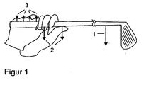
- FIG. 1 shows the force distribution in the upper reversal point of the swing, wherein arrow 1 symbolize the weight of the racket in the center of gravity, the arrows 2, the support force of the thumb and the peepholes 3, the force on the left palm.
- FIG. 1 makes it clear that even with a completely relaxed grip pressure the club weight in the upper reversal point of the swing are supported by both thumbs down got to. The fact that the club's center of gravity is clearly removed from the grip strengthens the power on the thumbs through leverage. The arrangement of a sensor in the thumb therefore leads to false signals.
- FIG. 1 illustrates further that in the upper reversal point of the momentum a large force is exerted on the palm, since the left palm supports the club weight upwards. This force is even greater than the force on the thumb, since in force equilibrium the only upward effective force occurs at this point.
- the arrangement of a sensor in the palm of the hand therefore also leads to false signals at the reversal point of the swing.
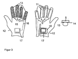
- the basic structure of a golf training glove according to the invention is for different sensor technologies in the Figures 3 and 4 shown for a left glove 12.
- FIG. 3 shows a glove 12 according to the invention with electrical sensors 13 which are arranged on the inside of the finger cots 11 over its entire length.
- the sensors 13 are located in pockets whose outer skin 14 is indicated on the right in the image.
- the terminals 15 of the sensors 13 are connected via connecting lines 16 with a transmitter 17 in combination, which is housed in a closure 18 for the glove 12 on the top thereof.
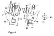
- FIG. 4 shows a glove 19 in which air cushion 21 pneumoelectric sensors 21, 24 are located only in the first two segments of the finger cots 11.
- An elastic bead 25 surrounds the air cushions 21.
- the beater 5 rests on the bead 25 and the air cushion 21.
- the air bags 21, bridging the two front segments of each fingerstall, are connected to each other with hoses 22.
- a further hose 23 connects each pair of airbags in a fingerstall 11 with an electropneumatic transducer 24, wherein each transducer 24 is in turn connected via electrical connection lines 16 to the evaluation electronics 17 in the glove closure 18.
- the sensors 21, 24 provide an analog measurement value for each finger, which is further processed in the evaluation electronics 17 after analog-to-digital conversion by a digital microcontroller.
- the task of this evaluation electronics 17 is to decide whether the grip pressure has exceeded a critical value as a function of the determined pressure values of the individual fingers and to signal this by means of light, sound or vibration.
- the question of whether an alarm should be triggered depends on the threshold and the duration of exceeding this value. It is possible to set a separate threshold for each individual finger. In any case, at least one common threshold for all the sensors 21, 24 in the fingerlings 11 is infinitely or in stages adjustable to set certain levels of difficulty (beginners, advanced). In addition, a discrimination of the threshold between the left and right glove 12 may be provided.
- the measured sensor values can be filtered, for example, with a low-pass filter.
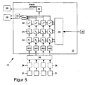
- FIG. 5 The basic block diagram of a transmitter 17 is in FIG. 5 shown.
- a total of 27 designated microcontroller is the measured value processing and coordination of the input and output elements 26,28.
- the entries are made in the Figures 3 . 4 and 6 recognizable keys, while the output via optical and acoustic signaling means 28, such as a display or speakers done.
- the user profile includes individual threshold values for the measured values acquired by each sensor 21, 24, as well as values for scaling and temporal smoothing of the measured values of each sensor 21, 24.
- the threshold value comparison of the measured values of the sensors 21, 24 takes place in comparators 32 for the signal path of each individual sensor.
- low-pass filters 31 for the time smoothing and damping or amplification elements 33 for the scaling are located in the signal path. If one of the comparators 32 determines that the measured value exceeds the threshold value specified for the respective user profile, this is indicated with the signaling means 28 for each signal path.
- the acoustic signaling means 28 is preceded by a voltage-controlled oscillator 34.
- the voltage controlled oscillator 34 generates depending on the output signal generated by the comparator 32 different frequency output voltages that produce, for example, in a speaker different high tones. Depending on the size of Schwellwertüberschreitung therefore different acoustic signals are generated.
- the outputs of all comparators 32 are connected to an OR circuit 35. This likewise dissolves via the further optical / acoustic signaling means 28 an alarm when only one of the comparators 32 detects a threshold exceeded.
- the transmitter 17 for each measuring channel On the input side, the transmitter 17 for each measuring channel to an analog / digital converter A / D, which converts the analog measurement signals from the pneumoelectric converter 24 behind a signal processing 36 into digital signals.
- the damping of the little finger is appropriate, since the club grip triggers an increased pressure on the little finger during the swing release. So that this additional pressure on the little finger is not erroneously detected as too high grip pressure by the comparator 32, the measured value is attenuated at the little finger, while the measured values are slightly strengthened at the index finger and the weaker middle and ring fingers relative to the index finger.
- FIG. 6 shows a glove 37 in which the electropneumatic sensors 21, 24 are arranged so that the pressure exerted by the player on the handle pressure is detected largely independent of an ideal grip position can.
- the finger cots 11 of the glove 37 are divided into three segments 38 a - c, wherein in the finger cotters for receiving the little finger, the ring finger and the middle finger, the air cushion 21 of the sensors 21,24 are arranged in the first segment 38 a and in the Fingerling for receiving the index finger the air cushion 21 is arranged in the second segment 38 b.
- the individual airbags 21 are connected via hoses 23 with the transducers 24 in connection.
- the pneumoelectric transducers 24 provide analog signals that after the analog / digital conversion in the transmitter 17 after FIG. 5 be further processed.
- the air bags 21 are filled with foam 39, which holds the air bag 21 in a defined form.
- the transmitter 17 is also integrated in this glove 37 in the closure 18 and has coincident input and output elements 26,28.
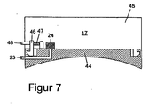
- FIG. 7 finally shows a side view of a transmitter 17, which is detachably connected to the glove 12, 19 and 37, respectively.
- a transmitter 17 which is detachably connected to the glove 12, 19 and 37, respectively.
- the transmitter 17 receiving housing 45 is releasably hooked.
- the hooks 46 is designed to be movable against the force of a spring 47. By actuating a pin 48 extending through the wall of the housing 45, the movable hook 46 can be displaced so that the housing 45 is released.
- the coupling of the pneumoelectric converter 24 with the hose lines 23 takes place in that the end pieces of the hose lines engage in corresponding receptacles of the transducer 24.
- electrical sensors in the finger cots lead from the sensors leading electrical lines in contact surfaces on the surface of the base 44, which with corresponding contact surfaces on the bottom of the housing 45 cooperate.
- Detachable transmitter 17 can continue to be used when the glove is worn. Only the relatively inexpensive air bag 21 including the tubes 23 welded thereto are replaced.
- Movement upswing 36th signal conditioning 9th Sensor fingerling 37th Glove 10th - 38 a) - c) segments 11th Fingerlinge 39th foam 12th Glove 40th - 13th sensor 41st Keys 14th shell 42nd user profile 15th connection 43rd display 16th connecting line 44th base 17th evaluation 45th casing 18th shutter 46th hook 19th Glove 47th feather 20th - 48th pen 21st air cushion 22nd tube 23rd tube 24th converter 25th bead 26th Input / output element 27th microcontroller 28th Opt./akust. signaling means
Abstract
Description
Die Erfindung betrifft einen Golftrainingshandschuh mit Sensoren zur Auslösung eines wahrnehmbaren Signals bei fehlerhafter Grifftechnik des Golfschlägers sowie mit Fingerlingen zur Aufnahme von Daumen, Zeigefinger, Mittelfinger, Ringfinger und kleinem Finger.The invention relates to a golf training glove with sensors for triggering a perceptible signal in case of faulty grip technique of the golf club and finger cots for receiving thumb, forefinger, middle finger, ring finger and little finger.
Derzeit existieren Trainingshilfen für Golfspieler, die im wesentlichen auf mechanische Aspekte des Golfschwunges zielen und dem Spieler das Erlernen von richtigen Positionen und Bewegungsrichtungen in bestimmten Schwungphasen erleichtern sollen. Hierbei wird jedoch ein weiterer wichtiger Aspekt vernachlässigt bzw. sogar verhindert, nämlich dass der Spieler möglichst ohne übermäßige Körperspannung schwingen sollte. Diese Anspannung hat mehrere schädliche Auswirkungen:Currently there are training aids for golfers, which are aimed essentially at mechanical aspects of the golf swing and the player to facilitate the learning of correct positions and directions of movement in certain phases of swing. Here, however, another important aspect is neglected or even prevented, namely that the player should swing as possible without excessive body tension. This tension has several harmful effects:
Angespannte Handgelenke verhindern, dass sich die im Schlägerkopf gespeicherte Bewegungsenergie nicht oder zum falschen Zeitpunkt entlädt.Tense wrists prevent the kinetic energy stored in the club head from discharging at the wrong time.
Durch angespannte Unterarme wird ein gegenseitiges Rotieren der Unterarme und sogenanntes Freigeben des Schlägerkopfes blockiert, was zu verminderter Schlägerkopfgeschwindigkeit und fehlerhafter Ausrichtung des Schlägerblattes im Treffzeitpunkt führt.Tense forearms block mutual rotation of the forearms and so-called clubhead release, resulting in decreased clubhead speed and incorrect alignment of the clubface at the time of the meeting.
Bestimmte Muskelpartien im Körper arbeiten gegeneinander und reduzieren die Schwunggeschwindigkeit indem die natürliche Bewegung des Schlägers blockiert wird.Certain muscle parts in the body work against each other and reduce the swing speed by blocking the natural movement of the racket.
Ein Golfspieler, der sich dieser Zusammenhänge nicht bewusst ist, wird mit dem Willen, den Ball möglichst weit schlagen zu wollen, schädliche Spannung in den Händen (und daraus folgend in den Unterarmen und anderen Körperpartien) aufbauen, und das genaue Gegenteil erreichen, nämlich zu kurze und unpräzise Schläge.A golfer who is unaware of these relationships will, with the will to hit the ball as far as possible, build up harmful tension in the hands (and consequently in the forearms and other body parts), and To achieve the exact opposite, namely too short and imprecise blows.
Die
Mit dieser Lösung lässt sich lediglich sicher stellen, dass der Golfschläger mit einer Mindestkraft festgehalten wird. Die Anordnung der Sensoren ist jedoch nicht in der Lage, unerwünschte, schädliche Spannungen in den Händen zu kontrollieren und zu vermeiden.With this solution, you can only make sure that the golf club is held with a minimum force. However, the arrangement of the sensors is not able to control unwanted, harmful voltages in the hands and avoid.
Aus der
Auch dieser Golftrainingshandschuh kann nicht vermeiden, dass schädliche Spannungen in den Händen aufgebaut und in Folge dessen zu kurze und unpräzise Schläge ausgeführt werden. Das Gegenteil ist vielmehr der Fall. Wird der Golfschläger mit hoher Muskelspannung, also verkrampft gehalten, kommt es auf Grund dieses Golftrainingshandschuhs keinesfalls zu einem Ansprechen der Signalgeber.Also, this golf training glove can not avoid that harmful tensions built up in the hands and as a result, too short and imprecise blows are performed. The opposite is the case. If the golf club held with high muscle tension, so cramped, it comes due to this golf training glove under no circumstances to a response of the signal generator.
Die
Die
Ein weiterer Nachteil besteht darin, dass ebenso wie bei der Platzierung des Drucksensors in dem Daumen gemäß der
Die
In einer Ausgestaltung des Golfhandschuhs sind zwei Kraftsensoren an der Handinnenfläche des Handschuhs an definierten Positionen angeordnet. Diese Kraftsensoren sind über ein Kabel mit einer Elektronik verbunden. In einer anderen Ausgestaltung des Golfhandschuhs wird von jedem Kraftsensor eine variable Frequenz als Ausgangssignal erzeugt. Sämtliche Sensoren sind in dem jeweils ersten Segment jedes Fingerlings des Handschuhs einschließlich demjenigen zur Aufnahme des Daumens angeordnet, wobei jeder Sensor mit einer Elektronik verbunden ist.In one embodiment of the golf glove, two force sensors are arranged on the palm of the glove at defined positions. These force sensors are connected via a cable to an electronic system. In another embodiment of the golf glove, a variable frequency is generated by each force sensor as an output signal. All of the sensors are disposed in the respective first segment of each fingerguard of the glove, including that for receiving the thumb, each sensor being connected to electronics.
Die
Ausgehend von diesem Stand der Technik liegt der Erfindung die Aufgabe zugrunde, einen Golftrainingshandschuh zu schaffen der die vorgenannten Nachteile nicht aufweist, insbesondere bei korrekter Grifftechnik keine Fehlsignalisierungen erzeugt und den Spieler dabei unterstützt, schädliche Spannung in den Händen während des Golfschwungs zu vermeiden.Based on this prior art, the present invention seeks to provide a golf training glove which does not have the aforementioned disadvantages, especially with correct grip technology generates no false signals and helps the player to avoid harmful tension in the hands during the golf swing.
Die Erfindung basiert auf dem Gedanken, dass die Finger den Griff umschließen und als Aktuatoren den eigentlichen Griffdruck aufbauen. Eine Messung an dieser Stelle liefert die am wenigsten verfälschten Resultate.The invention is based on the idea that the fingers enclose the handle and build up the actual grip pressure as actuators. A measurement at this point provides the least distorted results.
Im einzelnen wird die Aufgabe bei einem Golftrainingshandschuh der eingangs erwähnten Art dadurch gelöst, dass die Sensoren zumindest an den Fingerlingen zur Aufnahme von Zeigefinger, Mittelfinger und Ringfinger angeordnet sind und das wahrnehmbare Signal bei einem zu hohen Griffdruck auslösen und dass kein Sensor (21) an dem Daumen des Handschuhs (12,19,37) angeordnet ist.In detail, the object is achieved in a golf training glove of the type mentioned above in that the sensors are arranged at least on the fingerlings for receiving index finger, middle finger and ring finger and the perceptible signal at one trigger high grip pressure and that no sensor (21) on the thumb of the glove (12,19,37) is arranged.
Das wahrnehmbare Signal wird insbesondere von einer Auswerteelektronik ausgelöst, wenn sich im Rahmen eines Schwellwertvergleichs der von den Sensoren erfassten Messwerte mit mindestens einem Schwellwert ergibt, dass ein zu hoher Griffdruck aufgebaut wurde. Auf die Platzierung eines Sensors in dem Daumen wird vorzugsweise verzichtet, da insbesondere der Drucksensor in dem Daumen des Handschuhs für Fehlsignalisierungen verantwortlich ist.The perceptible signal is triggered, in particular, by evaluation electronics if, as part of a threshold value comparison, the measured values recorded by the sensors result in at least one threshold value, and an excessively high grip pressure has been built up. The placement of a sensor in the thumb is preferably omitted since, in particular, the pressure sensor in the thumb of the glove is responsible for false signals.
Vorzugsweise werden die Drucksensoren in alle Fingerlinge außer dem Daumen in den Golftraingshandschuhs sowohl der linken als auch der rechten Hand eingebaut.Preferably, the pressure sensors are incorporated into all fingerlings other than the thumb in both the left and right hand golf training gloves.
In bevorzugter Ausgestaltung der Erfindung werden die Sensoren in eine Tasche eingearbeitet, die durch eine doppelte Außenhaut an der Fingerinnenseite gebildet wird.In a preferred embodiment of the invention, the sensors are incorporated in a pocket, which is formed by a double outer skin on the inside of the finger.
Als Sensortypen kommen insbesondere elektrische und pneumoelektrische Sensoren in Betracht. Als elektrischer Sensor kommt ein kapazitiver Sensor zum Einsatz, der den Vorteil hat, auch im gebogenen Zustand korrekte Ergebnisse zu liefern (im Gegensatz z.B. zum resistiven Sensor), und auch statische Kräfte erfasst (im Gegensatz zum piezoelektrischen-Sensor).As sensor types are in particular electrical and pneumoelectric sensors into consideration. As an electrical sensor, a capacitive sensor is used which has the advantage of providing correct results even when bent (as opposed to, for example, the resistive sensor), and also detects static forces (as opposed to the piezoelectric sensor).
In einer kostengünstigeren Lösung kann der Griffdruck jedoch auch mit pneumolektrischen Sensoren über Druckkammern, insbesondere in Form von Luftkissen erfolgen, die in jedem Fingerling des Handschuhes in einer Tasche eingearbeitet sind. Die Druckmessung erfolgt dann über einen elektropneumatischen Wandler, der über einen Schlauch mit dem jeweiligen Kissen verbunden ist. Um nicht bereits durch die alleinige Fingerkrümmung einen Überdruck zu messen, kann es sinnvoll sein, das Kissen eines Fingerlings in 2 oder 3 Segmente aufzuteilen, die mit einem Schlauch miteinander verbunden werden.In a more cost-effective solution, the grip pressure can also be done with pneumatic sensors via pressure chambers, in particular in the form of air bags, which are incorporated in each finger of the glove in a pocket. The pressure measurement then takes place via an electropneumatic converter, which is connected via a hose to the respective cushion. In order not to measure an excess pressure by the sole curvature of the fingers, it may be useful to use the pillow of a fingerstall in 2 or 3 Split segments, which are connected to each other with a hose.
Jedes Kissen kann zumindest teilweise von einem Profil aus elastischem Material umgeben sein, wobei die maximale Profilhöhe die Höhe des Kissens übersteigt, um das Kissen vor erhöhtem Druck zu schützen und dem Spieler einen direkteren Kontakt zum Schlägergriff zu geben. Das Profil kann in die Tasche des Fingerkissens eingebaut und beispielsweise als relativ fester Gummischlauch ausgebildet sein.Each cushion may be at least partially surrounded by a profile of resilient material, the maximum profile height exceeding the height of the cushion to protect the cushion from increased pressure and to give the player more direct contact with the racket handle. The profile can be installed in the pocket of the finger pad and formed, for example, as a relatively solid rubber hose.
Um die Formstabilität der Kissen zu gewährleisten besteht darüber hinaus die Möglichkeit, diese teilweise mit einem elastischen Material, insbesondere Schaumstoff zu füllen. Der gasdurchlässige Schaumstoff dient dazu, die Luftkissen der pneumoelektrischen Sensoren in einer definierten Form zu halten, auch dann, wenn das Luftkissen noch nicht mit dem elektropneumatischen Wandler über eine Leitung verbunden ist. Hierdurch wird die Herstellung des erfindungsgemäßen Golftrainingshandschuhs vereinfacht.In order to ensure the dimensional stability of the cushion there is also the possibility to fill them partially with an elastic material, in particular foam. The gas-permeable foam serves to hold the air cushions of the pneumoelectric sensors in a defined form, even if the air cushion is not yet connected to the electro-pneumatic converter via a line. As a result, the production of the golf training glove according to the invention is simplified.
Die Luftkissen bestehen insbesondere aus einer Kunststofffolie. Der als Leitung zur Verbindung des Luftkissens mit dem elektropneumatischen Wandler dienende Schlauch ist vorzugsweise mit dem Kissen verschweißt.The air cushions consist in particular of a plastic film. The hose serving as a conduit for connecting the air bag to the electro-pneumatic converter is preferably welded to the pad.
In vorteilhafter Ausgestaltung der Erfindung liefern die Sensoren analoge elektrische Signale, die in einer Auswerteelektronik nach einer Analog-/Digitalwandlung verarbeitet werden. Die Hauptaufgabe der Auswerteelektronik besteht darin, in Abhängigkeit der erfassten Messwerte an den Sensoren zu den einzelnen Fingern zu entscheiden, ob der Griffdruck einen kritischen Schwellwert überstiegen hat und dies gegebenenfalls zu signalisieren. In einer einfachen Ausgestaltung der Erfindung, wird ein einheitlicher Schwellwert für die Sensoren sämtlicher Fingerlinge festgelegt. Vorzugsweise erlaubt die Auswerteelektronik jedoch einen individuellen Schwellwertvergleich für die Messwerte jedes Sensors. Auf Grund des individuellen Schwellwertvergleichs lassen sich die bei korrekter Grifftechnik unterschiedlichen Kräfte an den einzelnen Fingern präzise berücksichtigen. Der Schwellwertvergleich mit den analogen elektrischen Signalen erlaubt darüber hinaus eine differenzierte Betrachtung der Greifkräfte für die linke und rechte Hand beim Golfschwung.In an advantageous embodiment of the invention, the sensors provide analog electrical signals that are processed in an evaluation after an analog / digital conversion. The main task of the evaluation electronics is to decide whether the handle pressure has exceeded a critical threshold value, depending on the detected measured values at the sensors for the individual fingers, and to signal this if necessary. In a simple embodiment of the invention, a uniform threshold for the sensors of all fingerlings established. However, the evaluation electronics preferably allow an individual threshold value comparison for the measured values of each sensor. Due to the individual threshold value comparison, the different forces on the individual fingers can be precisely taken into account with the correct grip technique. The threshold comparison with the analog electrical signals also allows a differentiated consideration of the gripping forces for the left and right hand during golf swing.
Damit kurzfristige Druckspitzen an einzelnen Sensoren, die auf Grund der Kinematik des Golfschwungs unvermeidbar oder sogar gewünscht sind, keine Fehlsignalisierung auslösen, weist die Auswerteelektronik Mittel zur zeitlichen Glättung oder Messwerte auf. Hierdurch wird sichergestellt, dass nur eine Mindestdauer anhaltende Überschreitungen des Schwellenwertes die Signalisierung auslösen. Zur zeitlichen Glättung können die Messwerte beispielsweise mit einem Tiefpass gefiltert werden. Zusätzlich oder alternativ kann die Auswerteelektronik Mittel zum Skalieren der Messwerte aufweisen. Durch die Skalierung werden die Messwerte entweder verstärkt oder gedämpft. Durch diese Maßnahme kann dem Umstand Rechnung getragen werden, dass jeder Finger bei subjektiv gleich empfundener Anspannung auf den ihm zugeordneten Sensor einen unterschiedlichen Druck ausübt. Beispielsweise ist der Zeigefinger stärker als der Ringfinger, so dass sich eine Verstärkung des Signals für den Ringfinger gegenüber dem Zeigefinger empfehlen kann. Andererseits übt der Schlägergriff zu Beginn des Schwungs einen erhöhten Druck auf den kleinen Finger aus. Damit dieser zusätzliche Druck auf den dem kleinen Finger zugeordneten Sensor nicht fälschlich als zu hoher Griffdruck interpretiert wird, empfiehlt es sich, die Messwerte dieses Sensors leicht zu dämpfen. Nimmt man den Messwert des Sensors am Zeigefinger als Bezugspunkt, hat sich eine Verstärkung der Messwerte der Sensoren an Mittel- und Ringfinger und eine Dämpfung des Messwertes des Sensors am kleinen Finger als vorteilhaft herausgestellt.So that short-term pressure peaks on individual sensors, which are unavoidable or even desired due to the kinematics of the golf swing, do not trigger false signaling, the evaluation electronics has means for smoothing out time or measured values. This will ensure that only a minimum period of persistent exceedances of the threshold will trigger the signaling. For temporal smoothing, the measured values can be filtered, for example, with a low-pass filter. Additionally or alternatively, the evaluation electronics may have means for scaling the measured values. Scaling either boosts or attenuates readings. By this measure, the circumstance can be taken into account that each finger exerts a different pressure on the sensor assigned to it with subjectively equal perceived tension. For example, the index finger is stronger than the ring finger, so that an amplification of the signal for the ring finger against the index finger can recommend. On the other hand, the club grip exerts increased pressure on the little finger at the beginning of the swing. So that this additional pressure on the sensor associated with the little finger is not wrongly interpreted as too high grip pressure, it is advisable to slightly dampen the measured values of this sensor. Taking the measured value of the sensor as a reference point on the forefinger, there has been an increase in the measured values of the sensors on the center and ring fingers and a damping of the sensor Measured value of the sensor on the little finger proved to be advantageous.
Ein Golfhandschuh ist bei regem Spielbetrieb einem starken Verschleiß ausgesetzt, so dass dieser nach einiger Zeit ersetzt werden muss. Die Auswerteelektronik des Golftrainingshandschuhs unterliegt jedoch praktisch keinem Verschleiß. In einer vorteilhaften Ausgestaltung der Erfindung ist daher die Auswerteelektronik lösbar mit dem Golftrainingshandschuh verbunden. Sie lässt sich zerstörungsfrei von dem verschlissenen Golftrainingshandschuh trennen und an einem neuen Golftrainingshandschuh anbringen. Dieser neue Golftrainingshandschuh enthält die elektrischen Sensoren oder im Falle pneumoelektrischer Sensoren, die Luftkissen einschließlich der Anschlussleitungen an den elektropneumatischen Wandler. Die elektropneumatischen Wandler sind vorzugsweise ebenfalls lösbar mit dem Golftrainingshandschuh verbunden und können bei dessen Austausch weiterverwendet werden.A golf glove is exposed to heavy wear during heavy game operation, so this must be replaced after some time. However, the transmitter of the golf training glove is subject to virtually no wear. In an advantageous embodiment of the invention, therefore, the transmitter is detachably connected to the golf training glove. It can be non-destructively separated from the worn golf training glove and attached to a new golf training glove. This new golf training glove contains the electrical sensors or, in the case of pneumoelectric sensors, the air cushions including the connecting cables to the electro-pneumatic converter. The electro-pneumatic transducers are also preferably detachably connected to the golf training glove and can be used in its replacement.
Die Verbindung der lösbaren Auswerteelektronik erfolgt über eine elektrische Kopplung zu den Zuleitungen zu den elektrischen Sensoren oder durch eine Kopplung der Luftschläuche an die elektropneumatischen Wandler.The connection of the detachable evaluation electronics via an electrical coupling to the leads to the electrical sensors or by coupling the air hoses to the electropneumatic converter.
Fehlsignalisierungen durch das auf die Hand einwirkende Schlägergewicht werden reduziert, wenn die Fingerlinge des Handschuhs in drei Segmente unterteilt sind, wobei die Sensoren in dem ersten oder dem ersten und zweiten Segment, ausgehend von der Spitze jedes Fingerlings, angeordnet sind. Dabei wird davon ausgegangen, dass das erste Segment jedes Fingerlings zur Aufnahme des distalen, das zweite Segment jedes Fingerlings zur Aufnahme des medialen und das dritte Segment jedes Fingerlings zur Aufnahme des proximalen Glieds des Fingers dient.False signatures due to the hand-acting racket weight are reduced when the fingerguards of the glove are divided into three segments, the sensors being located in the first or the first and second segments, starting from the tip of each finger-box. It is assumed that the first segment of each finger cot serves to accommodate the distal, the second segment of each finger cot for receiving the medial and the third segment of each finger cot for receiving the proximal member of the finger.
Um weitgehend unabhängig von einer idealen Griffhaltung bei geringst möglicher Anzahl der Sensoren Fehlsignalisierungen auf Grund falscher Messwerte zu vermeiden, sind in den Fingerlingen zur Aufnahme des kleinen Fingers, des Ringfingers sowie des Mittelfingers die Sensoren in dem ersten Segment, ausgehend von der Spitze jedes Fingerlings, angeordnet und in dem Fingerling zur Aufnahme des Zeigefingers ist der Sensor in dem zweiten Segment, ausgehend von der Spitze des Fingerlings, angeordnet. Insbesondere bei pneumoelektrischen Sensoren hat sich herausgestellt, dass bei dieser Anordnung der Sensoren der Druck für die unterschiedlichsten Griffhaltungen am zuverlässigsten gemessen wird und die Sensoren vom Spieler als nicht störend wahrgenommen werden. Die Luftkisten der pneumoelektrischen Sensoren des kleinen Fingers, des Ringfingers sowie des Mittelfingers befinden sich möglichst nah am Übergang zum medialen Segment, d. h. in der Nähe des Gelenkes zum medialen Fingerglied. Für den Zeigefinger ist die Platzierung des Luftkissens des elektropneumatischen Sensors am medialen Segment, d. h. im Bereich des mittleren medialen Fingergliedes, vorteilhaft, weil der Zeigefinger den Schlägergriff weniger als die übrigen Finger umschließt, so dass im Bereich des medialen Fingerglieds der größte Druck vom Zeigefinger ausgeübt wird. Außerdem wird durch diese Platzierung automatisch der vom gegenüberliegenden Daumen ausgeübte Druck mitgemessen, da dieser bei einigermaßen korrekter Griffhaltung entgegengesetzt zum medialen Fingerglied des Zeigefingers auf der gegenüberliegenden Seite des Schlägergriffs aufliegt. Gleichzeitig lässt sich durch diese bevorzugte Anordnung der Luftkissen sicherstellen, dass die Luftkissen der Sensoren vollflächig belastet werden. Bei nur teilweiser Komprimierung der Luftkissen, wird nur ein Teil der Luft verdrängt und in Folge dessen ein falscher Messwert erfasst.In order to avoid false alarms due to incorrect measured values, largely independently of an ideal grip position with the least possible number of sensors, the sensors in the first segment, starting from the tip of each fingerstall, are in the fingerlings for receiving the small finger, the ring finger and the middle finger. arranged and in the fingerstall for receiving the index finger, the sensor in the second segment, starting from the tip of the fingerstall, arranged. In particular, in the case of pneumoelectric sensors, it has been found that, in this arrangement of sensors, the pressure for the most diverse gripping postures is measured most reliably and the sensors are perceived by the player as not disturbing. The air boxes of the pneumoelectric sensors of the little finger, the ring finger and the middle finger are as close as possible to the transition to the medial segment, ie in the vicinity of the joint to the medial phalanx. For the index finger, the placement of the air cushion of the electro-pneumatic sensor on the medial segment, ie in the region of the medial medial phalanx, is advantageous because the index finger surrounds the club grip less than the remaining fingers, so that in the area of the medial phalanx the greatest pressure is exerted by the index finger becomes. In addition, the pressure exerted by the opposite thumb pressure is also mitgemessen by this placement, since this rests in a reasonably correct grip opposite to the medial phalanx of the index finger on the opposite side of the racket handle. At the same time can be ensured by this preferred arrangement of the air cushion that the air cushion of the sensors are charged over the entire surface. With only partial compression of the air cushion, only a part of the air is displaced and as a result a wrong measured value is detected.
In einer weiteren Ausgestaltung der Erfindung weist die Auswerteelektronik Mittel zum drahtlosen Übertragen von Daten, insbesondere der in der Auswerteelektronik verarbeiteten Messwerte auf. Die Datenübertragung erlaubt die Protokollierung sowie die weitere Verarbeitung der Messwerte mit einem Personal Computer sowie die Sichtbarmachung von Fehlern bei der Greiftechnik auf dessen Anzeigeeinheit.In a further embodiment of the invention, the evaluation electronics have means for the wireless transmission of data, in particular the measured values processed in the evaluation electronics. The data transmission allows the logging as well as the further processing of the measured values with a personal computer as well as the visualization of errors in the gripping technique on its display unit.
Die Erfindung wird nachfolgend anhand der Figuren näher erläutert. Es zeigen:
Figur 1- die Kraftverteilung im oberen Umkehrpunkt eines Golfschwunges;
Figur 2- die Darstellung einer korrekten und inkorrekten Schwungauslösung;
Figur 3- ein erstes Ausführungsbeispiel eines erfindungsgemäßen Golftrainingshandschuhs;
- Figur 4
- ein zweites Ausführungsbeispiel eines erfindungsgemäßen Golftraingshandschuhs ;
Figur 5- ein prinzipielles Blockschaltbild einer Auswertelektronik;
Figur 6- ein drittes Ausführungsbeispiel eines erfindungsgemäßen Golftraingshandschuhs sowie
Figur 7- eine Seitenansicht einer lösbar mit dem Golftraingshandschuhs verbindbaren Auswerteelektronik.
- FIG. 1
- the force distribution at the upper reversal point of a golf swing;
- FIG. 2
- the representation of a correct and incorrect swing release;
- FIG. 3
- a first embodiment of a golf training glove according to the invention;
- FIG. 4
- A second embodiment of a Golftraingshandschuhs invention;
- FIG. 5
- a schematic block diagram of an evaluation electronics;
- FIG. 6
- a third embodiment of a Golftraingshandschuhs invention and
- FIG. 7
- a side view of a releasably connectable with the golf training glove evaluation.
Weitaus gravierender sind jedoch folgende Nachteile eines Sensors 4 in der Handinnenfläche eines Golftraingshandschuhs, die anhand von
Bei einer korrekten Schwungtechnik sollte der Schläger 5 zu Beginn des Schwunges mit der linken Hand 6 weggeschoben und nicht etwa mit der rechten Hand 7 weggezogen werden. Durch das unkorrekte Wegziehen mit der rechten Hand 7 spannen sich die Finger automatisch an, um der Trägheit des Schlägers 5 entgegenzuwirken, während die korrekte Schwungauslösung mit der linken Hand 6 keine schädliche Spannung aufbaut, da alle Finger entspannt bleiben können. Bei der korrekten Technik zur Schwungauslösung wird jedoch durch die Trägheit des Schlägers entgegen der durch die Pfeile 8 gekennzeichneten Bewegungsrichtung beim Aufschwung eine Kraft auf den Sensor 4 in der Handinnenfläche ausgeübt, so dass selbst bei einem völlig entspanntem, korrektem Griff der Sensor 4 auslöst. Werden hingegen erfindungsgemäß Sensoren 9 in die Fingerlinge 11 der rechten Hand 7 eingebaut, löst die falsche Schwungauslösetechnik diese Sensoren 9 aus, während die richtige Schwungtechnik die Sensoren nicht auslösen würde.With a correct swing technique, the
Der prinzipielle Aufbau eines erfindungsgemäßen Golftrainingshandschuhs ist für unterschiedliche Sensortechnologien in den
Für die Sensoren des in
Werden aus Kostengründen nur kleine Sensoren, d. h. solche mit nur einem Luftkissen je Sensor, eingesetzt, sollten diese in den oberen Segmenten der Fingerlinge 11 liegen. Für die Sensoren des Handschuhs der rechten Hand 7 gilt, dass aus Kostengründen auf einen Sensor im Fingerling 11 für den kleinen Finger verzichtet werden kann, da in den allermeisten Grifftechniken dieser nicht am Schläger anliegt.If, for reasons of cost, only small sensors, ie those with only one air cushion per sensor, are used, these should be used lie in the upper segments of the
Unabhängig von der verwendeten Technik liefern die Sensoren 21,24 für jeden Finger einen analogen Messwert, der in der Auswerteelektronik 17 nach einer Analog-/Digital Wandlung durch einen digitalen Mikrocontroller weiterverarbeitet wird. Aufgabe dieser Auswerteelektronik 17 ist es, in Abhängigkeit der ermittelten Druckwerte der einzelnen Finger zu entscheiden, ob der Griffdruck eine kritischen Wert überstiegen hat und dies durch Licht, Ton oder Vibration zu signalisieren.Regardless of the technique used, the
Die Frage, ob ein Alarm ausgelöst werden sollte, hängt von dem Schwellenwert sowie von der Dauer der Überschreitung dieses Wertes ab. Es ist möglich, für jeden einzelnen Finger ein gesonderten Schwellenwert festzulegen. In jedem Fall ist zumindest ein gemeinsamer Schwellenwert für sämtliche Sensoren 21, 24 in den Fingerlingen 11 stufenlos oder in Stufen einstellbar, um bestimmte Schwierigkeitsgrade einzustellen (Anfänger, Fortgeschrittener). Außerdem kann eine Unterscheidung des Schwellenwertes zwischen dem Handschuh 12 für die linke und rechte Hand 6,7 vorgesehen werden.The question of whether an alarm should be triggered depends on the threshold and the duration of exceeding this value. It is possible to set a separate threshold for each individual finger. In any case, at least one common threshold for all the
Damit zufällige Messfehler (Druckspitzen) und nur kurzzeitige, aber gewünschte Überschreitungen (z.B. im Zeitpunkt des Ball- bzw. Bodenkontaktes) keine Fehlsignalisierung auslösen, sollen nur längerfristige Überschreitungen des Schwellenwertes die Signalisierung auslösen. Hierzu können die gemessenen Sensorwerte z.B. mit einem Tiefpass gefiltert werden.So that random measurement errors (pressure peaks) and only short-term, but desired exceedances (eg at the time of contact with the ball or ground) do not trigger false signals, only longer-term exceedances of the threshold value should trigger the signaling. For this purpose, the measured sensor values can be filtered, for example, with a low-pass filter.
Das prinzipielle Blockschaltbild einer Auswerteelektronik 17 ist in
Über die Tasten der Auswerteelektronik 17 wird ein Benutzerprofil in einen Speicher 29, beispielsweise ein "Look-Up-Table" eingegeben. Das Benutzerprofil umfasst individuelle Schwellwerte für die von jedem Sensor 21,24 erfassten Messwerte, sowie Werte zur Skalierung und zeitlichen Glättung der Messwerte jedes Sensors 21,24. Der Schwellwertvergleich der Messwerte der Sensoren 21,24 erfolgt in Komparatoren 32 für den Signalweg jedes einzelnen Sensors. In dem Signalweg befinden sich darüber hinaus Tiefpassfilter 31 für die zeitliche Glättung sowie Dämpfungs- bzw. Verstärkungselemente 33 für die Skalierung. Stellt einer der Komparatoren 32 fest, dass der Messwert den für das jeweilige Benutzerprofil vorgegebenen Schwellwert überschreitet, wird dies für jeden Signalweg mit den Signalisierungsmitteln 28 angezeigt. Dem akustischen Signalisierungsmittel 28 ist ein spannungsgesteuerter Oszillator 34 vorgeschaltet. Der spannungsgesteuerte Oszillator 34 erzeugt abhängig von dem vom Komparator 32 erzeugten Ausgangssignal unterschiedlich frequente Ausgangsspannungen, die beispielsweise in einem Lautsprecher unterschiedlich hohe Töne erzeugen. Je nach Größe der Schwellwertüberschreitung werden daher unterschiedlich akustische Signale erzeugt.About the buttons of the
Darüber sind die Ausgänge sämtlicher Komparatoren 32 mit einer Oder-Schaltung 35 verbunden. Diese löst ebenfalls über die weiteren optischen/akustischen Signalisierungsmittel 28 einen Alarm aus, wenn lediglich einer der Komparatoren 32 eine Schwellwertüberschreitung feststellt.In addition, the outputs of all
Auf der Eingangsseite weist die Auswerteelektronik 17 für jeden Messkanal einen Analog-/Digitalwandler A/D auf, der die analogen Messsignale aus dem pneumoelektrischen Wandler 24 hinter einer Signalaufbereitung 36 in digitale Signale wandelt.On the input side, the
Als Skalierungsfaktoren X1 - X4 für die Dämpfungs- bzw. Verstärkungselemente 33 sind beispielsweise folgende Faktoren praktikabel, wobei X1 den Messwerten des Sensors des Zeigefingers, X2 den Messwerten des Sensors des Mittelfingers, X3 den Messwerten des Sensors des Ringfingers und X4 den Messwerten des Sensors des kleinen Fingers zugeordnet ist:
- X1 = 1,0
- X2 = 1,0 - 1,2
- X3 = 1, 0 - 1,25
- X4 = 0,8 - 0,95
- X1 = 1.0
- X2 = 1.0 - 1.2
- X3 = 1, 0 - 1.25
- X4 = 0.8 - 0.95
Die Dämpfung des kleinen Fingers ist zweckmäßig, da der Schlägergriff bei der Schwungauslösung einen verstärkten Druck auf den kleinen Finger auslöst. Damit dieser zusätzliche Druck auf den kleinen Finger nicht fälschlicherweise als zu hoher Griffdruck von dem Komparator 32 erfasst wird, wird der Messwert am kleinen Finger gedämpft, während die Messwerte an den gegenüber dem Zeigefinger schwächeren Mittel- und Ringfingern gegenüber dem Zeigefinger geringfügig verstärkt werden.The damping of the little finger is appropriate, since the club grip triggers an increased pressure on the little finger during the swing release. So that this additional pressure on the little finger is not erroneously detected as too high grip pressure by the
Die Luftkissen 21 sind mit Schaumstoff 39 gefüllt, der die Luftkissen 21 in einer definierten Form hält. Die Auswerteelektronik 17 ist auch bei diesem Handschuh 37 in den Verschluss 18 integriert und weist übereinstimmend Ein- und Ausgabeelemente 26,28 auf.The
Die Kopplung der pneumoelektrischen Wandler 24 mit den Schlauchleitungen 23 erfolgt dadurch, dass die Endstücke der Schlauchleitungen in entsprechende Aufnahmen der Wandler 24 eingreifen. Bei elektrischen Sensoren in den Fingerlingen münden die von den Sensoren führenden elektrischen Leitungen in Kontaktflächen an der Oberfläche des Sockels 44, die mit entsprechenden Kontaktflächen an der Unterseite des Gehäuses 45 zusammenwirken.The coupling of the
Die abnehmbare Auswerteelektronik 17, lässt sich weiter verwenden, wenn der Handschuh verschlissen ist. Lediglich die relativ preiswerten Luftkissen 21 einschließlich der daran angeschweißten Schläuche 23 werden ausgetauscht.
Claims (22)
- A golf training glove with sensors for triggering a perceptible signal in the event of an incorrect gripping technique of the golf club, with finger stalls for receiving thumb, index finger, middle finger, ring finger and little finger, characterised in that the sensors (13, 21, 24) are disposed at least on the finger stalls (11) for receiving index finger, middle finger and ring finger, and trigger the perceptible signal if a gripping pressure is too high and that no sensor (21) is disposed on the thumb of the glove (12, 19, 37).
- The golf training glove according to claim 1, characterised in that another sensor (13, 21, 24) is disposed on the finger stall (11) for the little finger.
- The golf training glove according to claim 1 or 2, characterised in that the sensors (13, 21, 24) are disposed on the inner side of the finger stalls (11).
- The golf training glove according to any one of claims 1 to 3, characterised in that the sensors (13, 21, 24) are incorporated in pockets (14).
- The golf training glove according to any one of claims 1 to 4, characterised in that the sensors are configured as electrical sensors (13).
- The golf training glove according to claim 5, characterised in that the electrical sensors (13) are capacitive sensors.
- The golf training glove according to any one of claims 1 to 4, characterised in that the sensors are configured as pneumo-electric sensors (21, 24).
- The golf training glove according to claim 7, characterised in that the pneumo-electric sensors (21, 24) comprise a plurality of pressure chambers (21) interconnected by lines (22, 23).
- The golf training glove according to claim 7 or 8, characterised in that each pressure chamber (21) of the pneumo-electric sensor is connected via a line (23) to an electro-pneumatic converter (24) which converts the pressure fluctuations in each pressure chamber (21) into analogue electric signals.
- The golf training glove according to any one of claims 7-9, characterised in that each pressure chamber (21) of the pneumo-electric sensor (21, 24) is at least partially filled with an elastic, gas-permeable material (39).
- The golf training glove according to any one of claims 1 to 10, characterised in that the measured values detected by the sensors are converted into analogue electric signals which are processed in an electronic evaluation system following analogue/digital conversion.
- The golf training glove according to claim 11, characterised in that the electronic evaluation system (17) allows an individual threshold value comparison for the measured values of each sensor.
- The golf training glove according to claim 11 or 12, characterised in that the electronic evaluation system has means for scaling (33) and/or temporally smoothing (31) the measured values.
- The golf training glove according to claim 13, characterised in that the electronic evaluation system (17) has means (33) for the separate scaling and/or the separate temporal smoothing (31) of each measured value.
- The golf training glove according to any one of claims 11 to 14, characterised in that the electronic evaluation system (17, 45) is detachably connected to the golf training glove (12, 19, 37).
- The golf training glove according to claim 11 and 15, characterised in that the electronic evaluation system (17) including all the electro-pneumatic converters (24) is detachably connected to the golf training glove (19, 37).
- The golf training glove according to any one of claims 1 to 16, characterised in that the finger stalls (11) of the glove (12) are divided into three segments, wherein the sensors are disposed in the first or the first and second segment (33a, 38b) starting from the tip of each finger stall (11).
- The golf training glove according to claim 3 and 17, characterised in that a first pressure chamber (21) is disposed in the region of the first segment (38a) and a second pressure chamber (21) is disposed in the region of the second segment (38b).
- The golf training glove according to any one of claims 1 to 16, characterised in that the finger stalls (11) of the glove (12) are divided into three segments (38a, 38b, 38c), wherein in the finger stalls for receiving the small finger, the ring finger and the middle finger, the sensors (9) or the pressure clambers (21) of the sensors (21, 24) are disposed in the first segment (38a) starting from the tip of each finger stall (11) and in the finger stall for receiving the index finger, the sensor (9) or the pressure chamber (21) is disposed in the second segment (38b) starting from the tip of the finger stall (11).
- The golf training glove according to any one of claims 17-19, characterised in that the first segment (38a) of each finger stall (11) serves to receive the distal member, the second segment (38b) of each finger stall serves to receive the medial member and the third segment (38c) of each finger stall serves to receive the proximal member of the finger.
- The golf training glove according to any one of claims 8 to 10, characterised in that each pressure chamber (21) is at least partially surrounded by a profile (25) of elastic material, wherein the maximum profile height exceeds the height of the pressure chamber (21).
- The golf training glove according to any one of claims 11 to 21, characterised in that the electronic evaluation system (17) comprises means for wireless transmission of data.
Applications Claiming Priority (2)
| Application Number | Priority Date | Filing Date | Title |
|---|---|---|---|
| DE102005018527A DE102005018527A1 (en) | 2005-04-20 | 2005-04-20 | Golf training gloves |
| PCT/EP2006/002772 WO2006111245A1 (en) | 2005-04-20 | 2006-03-27 | Golf training glove |
Publications (2)
| Publication Number | Publication Date |
|---|---|
| EP1890779A1 EP1890779A1 (en) | 2008-02-27 |
| EP1890779B1 true EP1890779B1 (en) | 2010-12-01 |
Family
ID=36609302
Family Applications (1)
| Application Number | Title | Priority Date | Filing Date |
|---|---|---|---|
| EP06723750A Not-in-force EP1890779B1 (en) | 2005-04-20 | 2006-03-27 | Golf training glove |
Country Status (5)
| Country | Link |
|---|---|
| US (1) | US7780541B2 (en) |
| EP (1) | EP1890779B1 (en) |
| AT (1) | ATE490008T1 (en) |
| DE (2) | DE102005018527A1 (en) |
| WO (1) | WO2006111245A1 (en) |
Cited By (1)
| Publication number | Priority date | Publication date | Assignee | Title |
|---|---|---|---|---|
| DE102015214394A1 (en) * | 2015-07-29 | 2017-02-02 | H4X E.U. | Exercise device, system and method for monitoring a physical exercise |
Families Citing this family (57)
| Publication number | Priority date | Publication date | Assignee | Title |
|---|---|---|---|---|
| US8123624B2 (en) * | 2005-03-03 | 2012-02-28 | Theodore Weissenburger Caldwell | Shot Monitoring Watch |
| NZ551819A (en) * | 2006-12-04 | 2009-03-31 | Zephyr Technology Ltd | Impact detection system |
| KR100737845B1 (en) * | 2006-12-06 | 2007-07-13 | 김정용 | Golf glove for right grip and suitable swing |
| US8033916B2 (en) * | 2007-05-04 | 2011-10-11 | Theodore Caldwell | Grip pressure sensor |
| US7930131B2 (en) * | 2008-02-11 | 2011-04-19 | United States Bowling Congress, Inc. | Analyzing foot pressure of a bowler |
| WO2009146142A2 (en) * | 2008-04-03 | 2009-12-03 | University Of Washington | Clinical force sensing glove |
| US20100154097A1 (en) * | 2008-06-13 | 2010-06-24 | Steven Karl Roscher | Battery powered accessory glove |
| US20100144455A1 (en) * | 2008-10-10 | 2010-06-10 | Frank Ahern | Device and system for obtaining, analyzing, and displaying information related to a golfer's game play in real-time |
| US20100093457A1 (en) * | 2008-10-10 | 2010-04-15 | Ahern Frank W | Golf glove and grip providing for power and club parametrics signal transfer obtained in real-time |
| US20100262047A1 (en) * | 2009-04-08 | 2010-10-14 | Drexel University | Physical therapy systems and methods |
| US8033925B2 (en) * | 2009-06-04 | 2011-10-11 | Hardage George E | Golf putting and swing aid apparatus |
| US8680390B2 (en) | 2009-10-16 | 2014-03-25 | Kesumo Llc | Foot-operated controller |
| US8572764B2 (en) * | 2010-12-09 | 2013-11-05 | Dieter Thellmann | Exercising glove |
| EP2564709B8 (en) * | 2011-09-02 | 2014-02-19 | Fiat Group Automobiles S.p.A. | Method to produce a protective glove and glove made by such method |
| US8517850B1 (en) | 2012-12-11 | 2013-08-27 | Cobra Golf Incorporated | Golf club grip with device housing |
| US9076419B2 (en) | 2012-03-14 | 2015-07-07 | Bebop Sensors, Inc. | Multi-touch pad controller |
| JP2014025179A (en) * | 2012-07-27 | 2014-02-06 | Yamaha Corp | Glove with strain sensor |
| US9301563B2 (en) * | 2013-02-07 | 2016-04-05 | Nova Diagnostics, Llc | Pressure sensing glove |
| FR3006477B1 (en) * | 2013-05-29 | 2016-09-30 | Blinksight | DEVICE AND METHOD FOR DETECTING THE HANDLING OF AT LEAST ONE OBJECT |
| US11679319B2 (en) * | 2013-06-20 | 2023-06-20 | John Ramirez | Sport gloves |
| US9189022B2 (en) * | 2013-11-13 | 2015-11-17 | Symbol Technologies, Llc | Wearable glove electronic device |
| JP6027038B2 (en) * | 2014-02-13 | 2016-11-16 | 美津濃株式会社 | Measuring system and measuring device |
| KR101542781B1 (en) | 2014-02-26 | 2015-08-07 | 신양순 | Glove having the function of electrostatic touch |
| US9442614B2 (en) | 2014-05-15 | 2016-09-13 | Bebop Sensors, Inc. | Two-dimensional sensor arrays |
| US9965076B2 (en) | 2014-05-15 | 2018-05-08 | Bebop Sensors, Inc. | Piezoresistive sensors and applications |
| US9696833B2 (en) | 2014-05-15 | 2017-07-04 | Bebop Sensors, Inc. | Promoting sensor isolation and performance in flexible sensor arrays |
| US9753568B2 (en) | 2014-05-15 | 2017-09-05 | Bebop Sensors, Inc. | Flexible sensors and applications |
| US9710060B2 (en) * | 2014-06-09 | 2017-07-18 | BeBop Senors, Inc. | Sensor system integrated with a glove |
| US10362989B2 (en) | 2014-06-09 | 2019-07-30 | Bebop Sensors, Inc. | Sensor system integrated with a glove |
| US9554732B2 (en) | 2014-06-30 | 2017-01-31 | Everyday Olympian, Inc. | Modular physical activity monitoring system |
| US9220942B1 (en) | 2014-08-21 | 2015-12-29 | W.A.T. Sports, Llc | Load and lag golf glove |
| CN104207781A (en) * | 2014-08-22 | 2014-12-17 | 南昌大学 | Device and method for measuring finger pinching capability of parkinsonian |
| US20160069760A1 (en) * | 2014-09-10 | 2016-03-10 | Grip Plus Inc | Interactive pressure control system |
| JP6478315B2 (en) * | 2014-09-30 | 2019-03-06 | 国立大学法人大阪大学 | Hand mold for manufacturing rubber gloves with electrodes |
| US20170319937A1 (en) * | 2014-12-01 | 2017-11-09 | David Nevell | Golf training device |
| US9863823B2 (en) | 2015-02-27 | 2018-01-09 | Bebop Sensors, Inc. | Sensor systems integrated with footwear |
| US10082381B2 (en) | 2015-04-30 | 2018-09-25 | Bebop Sensors, Inc. | Sensor systems integrated with vehicle tires |
| US9827996B2 (en) | 2015-06-25 | 2017-11-28 | Bebop Sensors, Inc. | Sensor systems integrated with steering wheels |
| US9721553B2 (en) | 2015-10-14 | 2017-08-01 | Bebop Sensors, Inc. | Sensor-based percussion device |
| US9925450B2 (en) * | 2016-06-28 | 2018-03-27 | Stephen Phillip Landsman | Device to precisely align golf club face to target |
| JP6923871B2 (en) * | 2016-08-31 | 2021-08-25 | 日本光電工業株式会社 | Rehabilitation pegs and rehabilitation support system |
| CN107692378B (en) * | 2016-09-13 | 2019-05-07 | 南京华风泽自动化科技有限公司 | Using pressure sensor, the work mechanism gloves of control device and its working method |
| CN109579689B (en) * | 2017-09-29 | 2020-12-08 | 西门子公司 | Curvature measuring device |
| US11036293B2 (en) * | 2017-12-07 | 2021-06-15 | Flex Ltd. | Method for using fingers to interact with a smart glove worn on a hand |
| USD849166S1 (en) | 2017-12-07 | 2019-05-21 | Ssg International, Llc | Golf putter grip |
| US10099101B1 (en) | 2017-12-07 | 2018-10-16 | Ssg International, Llc | Golf club grip with sensor housing |
| US10884496B2 (en) | 2018-07-05 | 2021-01-05 | Bebop Sensors, Inc. | One-size-fits-all data glove |
| WO2020026299A1 (en) * | 2018-07-30 | 2020-02-06 | 株式会社日立製作所 | Operation information management system, and operation information management method |
| CN109044383A (en) * | 2018-09-26 | 2018-12-21 | 元文学 | A kind of multichannel device for pressure measurement and its application method |
| US10890970B2 (en) | 2018-12-24 | 2021-01-12 | Lasarrus Clinic And Research Center | Flex force smart glove for measuring sensorimotor stimulation |
| US11480481B2 (en) | 2019-03-13 | 2022-10-25 | Bebop Sensors, Inc. | Alignment mechanisms sensor systems employing piezoresistive materials |
| US11041772B2 (en) | 2019-03-25 | 2021-06-22 | Toyota Motor Engineering & Manufacturing North America, Inc. | Sensor diffusion stack materials for pressure sensing gloves and methods incorporating the same |
| US10712119B1 (en) * | 2019-09-05 | 2020-07-14 | Rocky Mountain Specialty Gear, Inc. | Pressure activated release cue for archery |
| US11771972B2 (en) * | 2020-06-18 | 2023-10-03 | Maceo Baston | Sports training system |
| CN111973403A (en) * | 2020-09-16 | 2020-11-24 | 上海司羿智能科技有限公司 | Method and device for assisted hand training of patient |
| JP6949407B1 (en) * | 2021-06-18 | 2021-10-13 | 峻之 石田 | Golf gloves for proper grip |
| CN114366564A (en) * | 2022-01-21 | 2022-04-19 | 法罗适(上海)医疗技术有限公司 | Hand rehabilitation training method and hand rehabilitation training system |
Family Cites Families (11)
| Publication number | Priority date | Publication date | Assignee | Title |
|---|---|---|---|---|
| IE52820B1 (en) * | 1982-05-07 | 1988-03-16 | William F Murray | A sports proctice glove |
| US5221088A (en) * | 1991-01-22 | 1993-06-22 | Mcteigue Michael H | Sports training system and method |
| DE4240531C1 (en) * | 1992-11-27 | 1994-02-10 | Frank Hofmann | Computer data entry device measuring positions and pressures of hand - includes glove with sensors of deg. of bending of fingers and forces exerted thereby, translated into signal frequencies |
| US5681993A (en) * | 1994-04-18 | 1997-10-28 | Heitman; Lynn Byron | Method and apparatus for measuring grip force |
| US5655223A (en) * | 1994-06-16 | 1997-08-12 | Cozza; Frank C. | Electronic golf glove training device |
| US5733201A (en) | 1996-06-10 | 1998-03-31 | Caldwell; Theodore W. | Golf training glove |
| US6016103A (en) | 1997-09-25 | 2000-01-18 | Leavitt; Larry | Sleep-detecting driving gloves |
| DE19854237A1 (en) * | 1998-03-07 | 2000-02-10 | Erker Hartmut | Second golf glove to be worn in addition to glove used currently as standard practice |
| GB2339025A (en) * | 1998-07-02 | 2000-01-12 | Univ Sheffield | Apparatus for hand grip analysis |
| US6772442B2 (en) * | 1999-06-10 | 2004-08-10 | Hartmut Erker | Golf glove |
| KR200253427Y1 (en) * | 2001-05-24 | 2001-11-17 | 권성우 | Functional Golf Gloves |
-
2005
- 2005-04-20 DE DE102005018527A patent/DE102005018527A1/en not_active Withdrawn
-
2006
- 2006-03-27 DE DE502006008444T patent/DE502006008444D1/en active Active
- 2006-03-27 EP EP06723750A patent/EP1890779B1/en not_active Not-in-force
- 2006-03-27 US US11/912,001 patent/US7780541B2/en not_active Expired - Fee Related
- 2006-03-27 AT AT06723750T patent/ATE490008T1/en active
- 2006-03-27 WO PCT/EP2006/002772 patent/WO2006111245A1/en not_active Application Discontinuation
Cited By (2)
| Publication number | Priority date | Publication date | Assignee | Title |
|---|---|---|---|---|
| DE102015214394A1 (en) * | 2015-07-29 | 2017-02-02 | H4X E.U. | Exercise device, system and method for monitoring a physical exercise |
| US9757618B2 (en) | 2015-07-29 | 2017-09-12 | H4X E.U. | Training device, system and method for monitoring a physical exercise |
Also Published As
| Publication number | Publication date |
|---|---|
| ATE490008T1 (en) | 2010-12-15 |
| US20080189827A1 (en) | 2008-08-14 |
| WO2006111245A1 (en) | 2006-10-26 |
| US7780541B2 (en) | 2010-08-24 |
| EP1890779A1 (en) | 2008-02-27 |
| DE102005018527A1 (en) | 2006-10-26 |
| DE502006008444D1 (en) | 2011-01-13 |
Similar Documents
| Publication | Publication Date | Title |
|---|---|---|
| EP1890779B1 (en) | Golf training glove | |
| US4892303A (en) | Sport fencing device | |
| DE69827811T2 (en) | Retaining ring clutch control unit | |
| EP2195100A1 (en) | Force sensor for racquet handle | |
| WO2007030235A3 (en) | Medical analysis and recording system | |
| EP0416347A1 (en) | Tennisracket | |
| DE102013006469A1 (en) | APPARATUS FOR CONTROLLING HEART-LUNG REANIMATION AT HEART REST IN AN INTEGRATED DEFIBRILLATOR | |
| DE2847867C2 (en) | Hand protection for karate athletes | |
| CN209108554U (en) | A kind of contractile racket | |
| EP3844468B1 (en) | Device for detecting the punch quality in contact sports | |
| CN208274875U (en) | A kind of sliceable sport mats used | |
| KR101933518B1 (en) | Elastic towel for self stretching | |
| DE102007056831B4 (en) | Racket with joint | |
| DE60013796T2 (en) | Device for avoiding hand contraction, especially during sleep | |
| CN219109586U (en) | Pulling force controllable nerve retractor | |
| CN204618244U (en) | A kind of department of neurology physical examination tool | |
| CN212700356U (en) | Orthopedics is with hand nursing exercise device | |
| CN208448529U (en) | A kind of relaxation training device | |
| CN214436281U (en) | Department of neurology rehabilitation uses hand training equipment | |
| CN213158560U (en) | Auxiliary hand support for transfusion | |
| CN207324002U (en) | A kind of adjustable table tennis bat of handle | |
| CN212305563U (en) | Music player | |
| CN211090259U (en) | Display screen of industrial sensing measurement and control system | |
| CN214808125U (en) | Novel hula hoop | |
| CN207493134U (en) | A kind of body-building hand protection device |
Legal Events
| Date | Code | Title | Description |
|---|---|---|---|
| PUAI | Public reference made under article 153(3) epc to a published international application that has entered the european phase |
Free format text: ORIGINAL CODE: 0009012 |
|
| 17P | Request for examination filed |
Effective date: 20071109 |
|
| AK | Designated contracting states |
Kind code of ref document: A1 Designated state(s): AT BE BG CH CY CZ DE DK EE ES FI FR GB GR HU IE IS IT LI LT LU LV MC NL PL PT RO SE SI SK TR |
|
| DAX | Request for extension of the european patent (deleted) | ||
| GRAP | Despatch of communication of intention to grant a patent |
Free format text: ORIGINAL CODE: EPIDOSNIGR1 |
|
| GRAS | Grant fee paid |
Free format text: ORIGINAL CODE: EPIDOSNIGR3 |
|
| GRAA | (expected) grant |
Free format text: ORIGINAL CODE: 0009210 |
|
| AK | Designated contracting states |
Kind code of ref document: B1 Designated state(s): AT BE BG CH CY CZ DE DK EE ES FI FR GB GR HU IE IS IT LI LT LU LV MC NL PL PT RO SE SI SK TR |
|
| REG | Reference to a national code |
Ref country code: GB Ref legal event code: FG4D Free format text: NOT ENGLISH |
|
| REG | Reference to a national code |
Ref country code: CH Ref legal event code: EP |
|
| REG | Reference to a national code |
Ref country code: IE Ref legal event code: FG4D |
|
| REF | Corresponds to: |
Ref document number: 502006008444 Country of ref document: DE Date of ref document: 20110113 Kind code of ref document: P |
|
| REG | Reference to a national code |
Ref country code: NL Ref legal event code: VDEP Effective date: 20101201 |
|
| PG25 | Lapsed in a contracting state [announced via postgrant information from national office to epo] |
Ref country code: LT Free format text: LAPSE BECAUSE OF FAILURE TO SUBMIT A TRANSLATION OF THE DESCRIPTION OR TO PAY THE FEE WITHIN THE PRESCRIBED TIME-LIMIT Effective date: 20101201 |
|
| LTIE | Lt: invalidation of european patent or patent extension |
Effective date: 20101201 |
|
| PG25 | Lapsed in a contracting state [announced via postgrant information from national office to epo] |
Ref country code: NL Free format text: LAPSE BECAUSE OF FAILURE TO SUBMIT A TRANSLATION OF THE DESCRIPTION OR TO PAY THE FEE WITHIN THE PRESCRIBED TIME-LIMIT Effective date: 20101201 Ref country code: CY Free format text: LAPSE BECAUSE OF FAILURE TO SUBMIT A TRANSLATION OF THE DESCRIPTION OR TO PAY THE FEE WITHIN THE PRESCRIBED TIME-LIMIT Effective date: 20101201 Ref country code: FI Free format text: LAPSE BECAUSE OF FAILURE TO SUBMIT A TRANSLATION OF THE DESCRIPTION OR TO PAY THE FEE WITHIN THE PRESCRIBED TIME-LIMIT Effective date: 20101201 Ref country code: SI Free format text: LAPSE BECAUSE OF FAILURE TO SUBMIT A TRANSLATION OF THE DESCRIPTION OR TO PAY THE FEE WITHIN THE PRESCRIBED TIME-LIMIT Effective date: 20101201 Ref country code: SE Free format text: LAPSE BECAUSE OF FAILURE TO SUBMIT A TRANSLATION OF THE DESCRIPTION OR TO PAY THE FEE WITHIN THE PRESCRIBED TIME-LIMIT Effective date: 20101201 Ref country code: BG Free format text: LAPSE BECAUSE OF FAILURE TO SUBMIT A TRANSLATION OF THE DESCRIPTION OR TO PAY THE FEE WITHIN THE PRESCRIBED TIME-LIMIT Effective date: 20110301 Ref country code: LV Free format text: LAPSE BECAUSE OF FAILURE TO SUBMIT A TRANSLATION OF THE DESCRIPTION OR TO PAY THE FEE WITHIN THE PRESCRIBED TIME-LIMIT Effective date: 20101201 |
|
| REG | Reference to a national code |
Ref country code: IE Ref legal event code: FD4D |
|
| PG25 | Lapsed in a contracting state [announced via postgrant information from national office to epo] |
Ref country code: GR Free format text: LAPSE BECAUSE OF FAILURE TO SUBMIT A TRANSLATION OF THE DESCRIPTION OR TO PAY THE FEE WITHIN THE PRESCRIBED TIME-LIMIT Effective date: 20110302 |
|
| PG25 | Lapsed in a contracting state [announced via postgrant information from national office to epo] |
Ref country code: CZ Free format text: LAPSE BECAUSE OF FAILURE TO SUBMIT A TRANSLATION OF THE DESCRIPTION OR TO PAY THE FEE WITHIN THE PRESCRIBED TIME-LIMIT Effective date: 20101201 Ref country code: IS Free format text: LAPSE BECAUSE OF FAILURE TO SUBMIT A TRANSLATION OF THE DESCRIPTION OR TO PAY THE FEE WITHIN THE PRESCRIBED TIME-LIMIT Effective date: 20110401 Ref country code: ES Free format text: LAPSE BECAUSE OF FAILURE TO SUBMIT A TRANSLATION OF THE DESCRIPTION OR TO PAY THE FEE WITHIN THE PRESCRIBED TIME-LIMIT Effective date: 20110312 Ref country code: EE Free format text: LAPSE BECAUSE OF FAILURE TO SUBMIT A TRANSLATION OF THE DESCRIPTION OR TO PAY THE FEE WITHIN THE PRESCRIBED TIME-LIMIT Effective date: 20101201 Ref country code: IE Free format text: LAPSE BECAUSE OF FAILURE TO SUBMIT A TRANSLATION OF THE DESCRIPTION OR TO PAY THE FEE WITHIN THE PRESCRIBED TIME-LIMIT Effective date: 20101201 Ref country code: PT Free format text: LAPSE BECAUSE OF FAILURE TO SUBMIT A TRANSLATION OF THE DESCRIPTION OR TO PAY THE FEE WITHIN THE PRESCRIBED TIME-LIMIT Effective date: 20110401 |
|
| PG25 | Lapsed in a contracting state [announced via postgrant information from national office to epo] |
Ref country code: SK Free format text: LAPSE BECAUSE OF FAILURE TO SUBMIT A TRANSLATION OF THE DESCRIPTION OR TO PAY THE FEE WITHIN THE PRESCRIBED TIME-LIMIT Effective date: 20101201 Ref country code: RO Free format text: LAPSE BECAUSE OF FAILURE TO SUBMIT A TRANSLATION OF THE DESCRIPTION OR TO PAY THE FEE WITHIN THE PRESCRIBED TIME-LIMIT Effective date: 20101201 Ref country code: PL Free format text: LAPSE BECAUSE OF FAILURE TO SUBMIT A TRANSLATION OF THE DESCRIPTION OR TO PAY THE FEE WITHIN THE PRESCRIBED TIME-LIMIT Effective date: 20101201 |
|
| BERE | Be: lapsed |
Owner name: BAUER, DAVID Effective date: 20110331 |
|
| PLBE | No opposition filed within time limit |
Free format text: ORIGINAL CODE: 0009261 |
|
| STAA | Information on the status of an ep patent application or granted ep patent |
Free format text: STATUS: NO OPPOSITION FILED WITHIN TIME LIMIT |
|
| PG25 | Lapsed in a contracting state [announced via postgrant information from national office to epo] |
Ref country code: MC Free format text: LAPSE BECAUSE OF NON-PAYMENT OF DUE FEES Effective date: 20110331 Ref country code: DK Free format text: LAPSE BECAUSE OF FAILURE TO SUBMIT A TRANSLATION OF THE DESCRIPTION OR TO PAY THE FEE WITHIN THE PRESCRIBED TIME-LIMIT Effective date: 20101201 |
|
| REG | Reference to a national code |
Ref country code: CH Ref legal event code: PL |
|
| 26N | No opposition filed |
Effective date: 20110902 |
|
| REG | Reference to a national code |
Ref country code: FR Ref legal event code: ST Effective date: 20111130 |
|
| REG | Reference to a national code |
Ref country code: DE Ref legal event code: R097 Ref document number: 502006008444 Country of ref document: DE Effective date: 20110902 |
|
| PG25 | Lapsed in a contracting state [announced via postgrant information from national office to epo] |
Ref country code: IT Free format text: LAPSE BECAUSE OF FAILURE TO SUBMIT A TRANSLATION OF THE DESCRIPTION OR TO PAY THE FEE WITHIN THE PRESCRIBED TIME-LIMIT Effective date: 20101201 Ref country code: BE Free format text: LAPSE BECAUSE OF NON-PAYMENT OF DUE FEES Effective date: 20110331 |
|
| PG25 | Lapsed in a contracting state [announced via postgrant information from national office to epo] |
Ref country code: FR Free format text: LAPSE BECAUSE OF NON-PAYMENT OF DUE FEES Effective date: 20110331 Ref country code: CH Free format text: LAPSE BECAUSE OF NON-PAYMENT OF DUE FEES Effective date: 20110331 Ref country code: LI Free format text: LAPSE BECAUSE OF NON-PAYMENT OF DUE FEES Effective date: 20110331 |
|
| REG | Reference to a national code |
Ref country code: AT Ref legal event code: MM01 Ref document number: 490008 Country of ref document: AT Kind code of ref document: T Effective date: 20110327 |
|
| PG25 | Lapsed in a contracting state [announced via postgrant information from national office to epo] |
Ref country code: AT Free format text: LAPSE BECAUSE OF NON-PAYMENT OF DUE FEES Effective date: 20110327 |
|
| PG25 | Lapsed in a contracting state [announced via postgrant information from national office to epo] |
Ref country code: LU Free format text: LAPSE BECAUSE OF NON-PAYMENT OF DUE FEES Effective date: 20110327 |
|
| PG25 | Lapsed in a contracting state [announced via postgrant information from national office to epo] |
Ref country code: TR Free format text: LAPSE BECAUSE OF FAILURE TO SUBMIT A TRANSLATION OF THE DESCRIPTION OR TO PAY THE FEE WITHIN THE PRESCRIBED TIME-LIMIT Effective date: 20101201 |
|
| PG25 | Lapsed in a contracting state [announced via postgrant information from national office to epo] |
Ref country code: HU Free format text: LAPSE BECAUSE OF FAILURE TO SUBMIT A TRANSLATION OF THE DESCRIPTION OR TO PAY THE FEE WITHIN THE PRESCRIBED TIME-LIMIT Effective date: 20101201 |
|
| PGFP | Annual fee paid to national office [announced via postgrant information from national office to epo] |
Ref country code: DE Payment date: 20170327 Year of fee payment: 12 |
|
| PGFP | Annual fee paid to national office [announced via postgrant information from national office to epo] |
Ref country code: GB Payment date: 20170327 Year of fee payment: 12 |
|
| REG | Reference to a national code |
Ref country code: DE Ref legal event code: R119 Ref document number: 502006008444 Country of ref document: DE |
|
| GBPC | Gb: european patent ceased through non-payment of renewal fee |
Effective date: 20180327 |
|
| PG25 | Lapsed in a contracting state [announced via postgrant information from national office to epo] |
Ref country code: DE Free format text: LAPSE BECAUSE OF NON-PAYMENT OF DUE FEES Effective date: 20181002 |
|
| PG25 | Lapsed in a contracting state [announced via postgrant information from national office to epo] |
Ref country code: GB Free format text: LAPSE BECAUSE OF NON-PAYMENT OF DUE FEES Effective date: 20180327 |